1
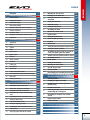
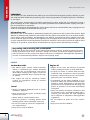
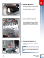
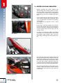
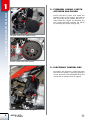
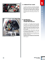
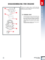
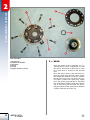
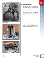
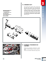
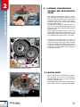
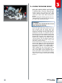
WORKSHOP MANUAL
www.betamotor.com
Foreword
2
3.6.2
Mounting the start-up device
33
1
Removing the engine from the vehicle
4
3.7
Primary gear and clutch unit
34
1.1
Exhaust manifold
5
3.7.1
35
1.2
Engine protection plat
5
Testing the clutch bell and replacing the
silent-block
1.3
Transmission oil plug
5
3.7.2
Testing the clutch discs
36
1.4
Water cooling radiator
6
3.7.3
Testing the springs
37
1.5
Flywheel casing, clutch actuator and pinion
8
3.7.4
Testing the clutch drum
37
1.6
Electronic control box
8
3.8
Assembling the clutch
38
1.7
Carburettor clamp
9
3.9
Internal cover of the clutch
40
1.8
Quadripole and monopole connector release
9
3.10
Ignition system
41
1.9
Engine bolts
10
3.10.1
Testing the ignition stator
41
2
Disassembling the engine
11
3.10.2
Stator and pick-up winding
41
2.1
Thermal unit
11
3.10.3
Flywheel
42
2.1.1
Head
12
3.11
Thermal unit
43
2.1.2
Cylinder
13
3.11.1
Testing the piston, piston pin and piston rings
43
2.1.3
Piston
13
3.11.2
Testing the cylinder and head
44
2.2
Intake system
14
3.12
Assembling the piston, piston ring, piston pin,
crank case/cylinder gasket and cylinder
46
2.3
Ignition system
14
3.12.1
Thickness check of cylinder/crankcases gasket
47
2.3.1
Flywheel
15
3.13
Assembling the head
49
2.3.2
Pick-up and stator
16
3.14
Intake system
50
2.4
Clutch unit
17
3.14.1
Testing the lamella pack
50
2.5
Primary gear
19
3.14.2
Mounting the intake system
50
2.6
Start-up devic
20
3.15
Start-up and gear lever
50
2.7
Gearbox unit
21
3.16
Water pump unit
51
2.7.1
External transmission control
21
3.16.1
Disassembling and reassembling the water pump
51
2.7.2
Internal transmission control and transmission gears
22
2.8
Motor shaft
22
4
Mounting the engine on the vehicle
and repositioning the components
52
2.9
Bearings and oil seals
23
4.1
General guidelines
52
3
Assembling and testing the engine
24
4.2
Coupling the engine to the frame
53
3.1
Testing the motor shaft and connecting rod
24
4.3
54
3.2
Mounting the complete motor shaft
25
Coupling the clutch actuator, pinion and
flywheel casing
3.3
Gearbox unit: testing and reassembling
25
4.4
Electronic control box
55
3.3.1
Testing the toothed wheels and shafts
25
4.5
Connecting the engine cable to the main system
and mounting the rear mudguard
55
3.3.2
Testing the forks, fork pins and desmodromic
device
26
4.6
56
3.3.3
Assembling the internal transmission control
27
Remounting the complete water radiator
and coil
3.4
Closing the engine casing
29
4.7
Engine protection plate
57
3.5
External transmission control
30
4.8
Exhaust manifold
58
3.5.1
Testing the complete gear shaft
30
Table of tightening torques of the engine components
59
3.5.2
Assembling the external transmission control
31
Table of tightening torques of the engine-frame
60
3.6
Start-up device
32
Engine specifications
60
3.6.1
Testing the ignition shaft and the assembly
32
Recommended lubricants and liquid
60
ENGLISH
INDEX
1
Foreword
www.betamotor.com
Foreword
This manual has been drafted for the motorcycle user and Technical Support operator, whereby it provides understandable information pertaining to the necessary operations of engine inspection, maintenance and repair.
This manual must be thoroughly read before operating the engine. Engine life is prolonged by having a
good knowledge of all the components and all the procedures to be followed when carrying out inspection and maintenance operations.
Schematic illustrations that highlight the subject matter have been included within the paragraphs for the
reader to immediately understand that being read.
Informative note
Betamotor S.p.A. is committed to continuously improve its products. For this reason, there may be slight
differences between that provided in this manual and the vehicle onto which you are to perform maintenance and/or repair operations. The Betamotor S.p.A. models are exported to many countries where different standards apply in relation to the Highway Code and approval procedures. Betamotor S.p.A. relies
on your comprehension of the information, therefore it considers it necessary to reserve the right to effect
changes to its products and technical documentation at any given time and without prior notice.
Respecting and protecting the environment
All that we do has repercussions on the entire planet and its resources. In order to protect the Community, Betamotor S.p.A. raises awareness amongst its Clients and Technical Support operators in
order for them to use the vehicle and dispose of its parts in compliance with applicable regulations
in terms of environmental pollution, disposal and recycling waste.
Safety
Carbon Monoxide
• The exhaust gases contain carbon monoxide,
which is a poisonous gas. Carbon monoxide
can cause loss of consciousness and lead to
death. When starting-up the engine, ensure the
area is well-ventilated. Never start-up the engine indoors.
• The engine can only be started-up indoors
if there are appropriate means to evacuate
exhaust gases.
Petrol
• Petrol is extremely flammable and in certain
conditions, explosive.
• Keep sources of heat, sparks and flames away
from the work area.
• Engine oil can cause skin diseases if repeated
and/or prolonged contact is made with skin.
• If engine oil comes in contact with your skin,
wash with soap and water as soon as possible.
• If contact is made with your eyes, rinse thoroughly with water and consult a doctor.
• If swallowed, do not induce vomiting so as to
prevent it from being absorbed into the lungs.
Consult a doctor immediately. If you think the
product has been absorbed into the lungs, the
person in question is to be taken immediately
to hospital.
• Spent oil contains hazardous substances that
are harmful to the environment. When this is
replaced, you must have the right equipment
for its disposal in compliance with applicable
regulations.
• Always work in a well-ventilated area.
• Never use petrol as a cleaning solvent. Avoid
• Do not dispose of spent oil in the environ-
• Do not use petrol to clean the components –
• Keep out of reach of children.
handling petrol, unless absolutely necessary.
use compressed air.
• Keep out of reach of children.
2
Engine oil
ment.
Coolant
• In certain situations, the ethylene glycol contai-
ned in the coolant is flammable and its flame
is invisible. Should the ethylene glycol ignite,
even though its flame is invisible, it will cause
burns.
• Coolant contains hazardous substances that are
harmful to the environment. When replacing
the coolant you must have the right equipment
for its disposal, in compliance with applicable
regulations.
• Prevent the coolant from coming into contact
• Do not dispose of coolant in the environment.
• Keep out of reach of children.
• The coolant (ethylene glycol) may cause skin
Hot parts
with hot parts. These parts can be hot enough
to ignite the flame.
irritation and is poisonous if swallowed.
• If the coolant comes into contact with your skin,
immediately remove any contaminated clothes
or shoes and wash with soap and water. If contact is made with your eyes, rinse thoroughly
with clean water and consult a doctor immediately. If swallowed, do not induce vomiting so
as to prevent it from being absorbed into the
lungs. The person in question must drink clean water and must also be taken immediately
to hospital. The product must be shown to the
medical staff.
Foreword
www.betamotor.com
• The engine and the exhaust system become
very hot and remain so for some time, even
after the engine is switched off. Wait for them
to cool before handling or intervening in parts
that are around them. Also use insulating gloves.
• In case of exposure to a high concentration of
vapours, the person in question must be moved
to an unpolluted area and if necessary, a doctor
must be called.
• Do not remove the radiator cap when the engi-
ne is still hot. Since the coolant is under pressure, it can spurt out violently and cause burns.
Warnings
The information contained in this paragraph is important for any operation to be carried out
correctly on the engine without causing damage.
• Thoroughly clean the motorcycle before disas-
• Always
• When
• When
sembling any parts.
disassembling, clean all the components and put them in containers maintaining
the same order of disassembly.
• Always use special tools where necessary and
every time this is required.
• Always
use the adhesives, sealants and lubricants where stipulated. Adhere with the guidelines given regarding their technical specifications.
replace parts such as seals, O-rings
and safety washers with brand new parts.
loosening or tightening nuts or screws,
always start with the larger ones or from the
centre. Always adhere with the tightening torque values given.
• Solely
used.
Betamotor original parts are to be
3
Removing the engine from the vehicle
Removing the engine from the vehicle
1
Before removing the engine from the vehicle,
thoroughly clean the entire motorbike and let it
dry, then place it on a stable kickstand.
Pictures 1 and 2 show the engine coupled with
the vehicle, seen from both the left and right
side, showing all the main components that must
be removed for the engine to be removed from
the vehicle.
1
4
1- Exhaust manifold
2- Engine protection plate
2
3- Oil drain plug
3
4- Cooling radiator
Picture 1
Left view of the engine coupled with the vehicle.
9
8
7
5
5- Flywheel casing
6- Clutch actuator
7- Pinion
6
8- Electronic control box
9- Carburettor clamp
Picture 2
Right view of the engine coupled with the vehicle.
4
Unscrew the two bolts that fasten the manifold flange to the cylinder in order to remove the exhaust manifold.
It is recommended to turn the handlebar to
one side to facilitate the operation.
The two bolts of the exhaust manifold flange.
1.2 Engine protection plate
Remove the engine protection plate by removing the four fastening screws from the
frame. Should the protection plate be particularly deformed, it is recommended to carefully beat it back into place or replace it.
1
Removing the engine from the vehicle
1.1 Exhaust manifold
The four screws of the engine protection plate.
1 .3 Transmission oil plug
Drain the transmission oil by removing the
relative plug.
Caution!
Spent oil contains hazardous substances that
are harmful to the environment. When replacing
the oil you must have the right equipment for its
disposal, in compliance with applicable regulations.
Do not dispose of spent oil in the environment.
The plug where the transmission oil is drained from.
5
Removing the engine from the vehicle
1
1 .4 Water cooling radiator
Before removing the water radiator you
should empty the cooling system by removing the drain screw found on the pump
body. Open the radiator cap and slightly tilt
the vehicle to the left to facilitate the liquid
flow.
It is recommended to perform this operation
after having removed the protection plate
so as to prevent the coolant from remaining
on the plate.
The liquid can be reused if it has a clear
blue colour.
Liquid drain plug.
Loosen the screw that fastens the coil support to the radiator. Once this is implemented, the coil and its support will be fastened
to the vehicle solely by the high and low
voltage cables.
The screw that fastens the coil support to
the radiator.
In order to prevent the cables from being
stretched, it is recommended to disconnect
the pipette -high voltage cable- from the
spark plug and fasten the frame with clamps.
The screws that fasten the left side to the tank.
A
B
C
Connectors A, B and C.
6
You must disconnect the thermal bulb and
the fan from the electrical system in order to
remove the radiator. Loosen the two screws
that fasten the left side to the tank in order
to access the relative connectors. Then disconnect connectors A and B, respectively,
from the electric fan and the thermal bulb.
To loosen the left side from the vehicle completely, simply disconnect connector C that
connects the map switch to the electronic
control box.
D
B
C
A
Disassembling the radiator.
Unscrew the lower pin A, the four upper
screws B (two on each side) and loosen the
two clamps C (one on each side) that connect the radiator to the engine.
Slightly turn the radiator forward and remove its two water pipes, simultaneously.
Lower the radiator in such a way that the
upper pin D comes out of its housing.
1
Removing the engine from the vehicle
1 .4
D
Complete radiator: the upper pin (D) is highlighted.
7
Removing the engine from the vehicle
1
1.5 Flywheel casing, clutch
actuator and pinion
Loosen the three screws that fasten the
flywheel casing to the engine. This will let
you access the clutch actuator, which is removed from the engine by loosening the
four screws indicated. Remove the pinion
by removing the specific Seeger ring.
The three screws of the flywheel casing.
The four screws of the clutch actuator.
1.6 Electronic control box
Disconnect the electronic control box from
the electrical system by pressing the flap A
on the connector, then pull upwards for the
control box to emerge from its support.
A
Extracting the control box from its support.
8
1 .7 Carburettor clamp
1
A
B
Removing the carburettor from the engine.
A
B
Quadripole and monopole connector.
In order to remove the carburettor from the
engine you must loosen the two flaps A and
B that fold around the intake collector 1
and sleeve 2 respectively, which connect it
to the filter box. Then pull the carburettor
towards the back part of the vehicle until it
is released from its housing inside the container.
1.8 Quadripole
and monopole
connector release
The engine is connected to the main system
by means of a quadripole and monopole
connector, which must be disconnected for
the engine to be removed from the vehicle.
Loosen the screws that fasten the rear mudguard to the frame and remove the mudguard by disconnecting the power cable of
the backlight.
Remove the clamps and pull the cables that
are along the left side of the frame, towards
the back part of the vehicle.
Pull the flap A that is on the female quadripole connector and then separate it from
the male connector.
Disconnect the monopole connector B and
remove the cable, downwards from the side
of the engine.
1
Removing the engine from the vehicle
2
9
1
Removing the engine from the vehicle
D
B
A
C
Engine bolts:
A) swing arm bolt;
B) upper bolt;
C) lower bolt;
D) bracket bolts.
1.9 Engine bolts
A
Swing arm bolt not being removed completely.
The engine is fastened to the frame by four
bolts: one at the front, one at the bottom,
one at the top and one at the back. The
description of the first of these four bolts
being removed is found in paragraph 1.4,
removal of the radiator. It is recommended
to remove the engine from the frame by
first removing bolt A at the back (swing arm
bolt), then the upper bolt B and lastly the
lower bolt C. The control box support will
also be removed when the nut from bolt B
is removed.
It is recommended to also loosen both bolts
D, so as to facilitate removing and reassembling the engine onto the frame.
Please note that bolt B does not have to
be removed completely for the engine to be
removed. In fact, it must be loosened enough for the engine to be removed from the
frame, thereby you will avoid removing the
swing arm from the frame.
10
Fasten the engine onto a solid and safe
support so as to work with ease and safely.
Then proceed as follows.
1
5
2
2.1 Thermal unit
6
3
The thermal unit consists of the external cap
1, the combustion chamber 2, the cylinder
3 and the piston 4. Assembly is completed
with the O-ring 5, the seal head 6, the casing-cylinder seal 7 and the seven copper
washers with the respective special screws
M7x31.
The description of these parts being disassembled is found further on.
2
Disassembling the engine
Disassembling the engine
7
4
Exploded view of the thermal unit.
11
2
3
Disassembling the engine
1
5
4
6
2
Head assembly.
1)
2)
3)
4)
5)
6)
12
External cap.
Combustion chamber.
Seal head.
O-ring.
Screws.
Copper washers 7x12x0.5
2 .1.1 Head
Once the water circuit is emptied, it is recommended to blow compressed air into
the sleeve connected to the head in order
to be sure there is no fluid in the thermal
unit.
Once the water sleeve is disconnected, loosen the spark plug, then the seven screws
that fasten the external cap to the cylinder.
Lift the head and once it is placed on a level surface, remove the spark plug. Lightly
press the spark plug housing to decouple
the combustion chamber from the external
cap. If necessary, proceed with the descaling procedures of the combustion chamber
and the internal part of the cap.
Remove the rubber tube that connects the
cylinder to the water pump after having loosened the clamp; turn the motor shaft until
the piston lies in the top dead centre and
loosen the four bolts A that fasten the cylinder to the base unit. Then gently remove the
cylinder by pulling it upwards.
Note: Should the cylinder be stuck to the
base unit, gently strike the cylinder in various points with a rubber mallet.
A
Disassembling the cylinder.
Disassembling the engine
2 .1.2 Cylinder
2
2.1.3 Piston
A
Place a clean cloth in the area below the
piston, between the two casings, in order to
prevent any foreign objects or solid residues
from falling into the base unit. Then use a
suitable tool to remove the piston pin lock
ring A. Working from the other side, unthread piston pin B as much as is needed to
release the piston assembly from the connecting rod. Remove the bearings assembly
C from the connecting rod.
Disassembling snap ring A.
D
C
A
B
Complete piston: A) piston pin lock ring; B) piston
pin; C) bearings assembly; D) piston.
13
Disassembling the engine
2
A
2 .2 Intake system
The intake system consists of the intake manifold B and the lamella pack C. To disassemble this, remove the four screws A that
fasten the intake manifold and the lamella
pack to the casings. Decouple the intake
manifold and seal D from the lamella pack.
Disassembling the intake manifold and lamella pack.
B
A
D
C
Exploded view of the intake container.
A)
B)
C)
D)
screws;
intake container;
lamella pack;
seal.
2 .3 Ignition system
B
A
D
F
E
C
Complete ignition system.
14
The ignition system consists of the flywheel
A, the stator windings B (stator for short)
and the magnetic pick-up C. The complete
stator is fastened to the support D with two
screws and the support is fastened to the
right casing with three screws. The flywheel
is fastened to the motor shaft by the special nut E. The safety washer F is interposed
between the flywheel and nut. Proceed as
follows to disassemble the parts.
Keep the flywheel in place by means of a
special universal device A. Unscrew the
nut that blocks the flywheel to the motor
shaft. Screw the special extractor B (code
1480210.000) into the internal thread of
the flywheel and extract it by tightening the
central screw that presses onto the motor
shaft. During this process, the flywheel is
kept in place by using a simple flat spanner.
A
Disassembling the engine
2 .3.1 Flywheel
2
Blocking the flywheel with the universal tool.
B
Decoupling the flywheel from the motor shaft
by means of extractor B (code 1480210.000)
Note: the GB version is provided with an extra mass which must be removed before disassembling the flywheel. In order to do this,
heat the two screws and then remove them.
15
Disassembling the engine
2
2
B
Loosen the two screws A and the three
screws B that fasten pick-up 1 and stator
2, respectively, to the engine casing. Then
remove the pick-up and stator assembly.
B
A
Stator 1 and pick-up 2 assembly.
16
2 .3.2 Pick-up and stator
1
A
You must remove the transmission control
lever and start-up lever to access the clutch
unit. Loosen the seven screws shown in the
picture that couple the internal cover of the
clutch A to the casing.
The seven screws that couple the internal cover of
the clutch to the casing.
The clutch unit consists of the components
shown in the picture below.
2
Disassembling the engine
2 .4 Clutch unit
Clutch unit: main components.
3) Washer 20x35x1;
5) Bushing;
9) Clutch bell;
10) Special washer;
11) Clutch drum;
12) Steel disc (No. 5);
13) Friction disc (No. 6);
14) Pressure plate cap;
15) Spring (No. 6);
16) Washer 6x18 (No. 6);
17) Screw 6x16 (No. 6);
18) Thrust bearing cage 15x18x2;
19) Pressure plate;
20) Ball;
21) Clutch control rod.
To remove this, unthread the clutch control
rod 21 and bend it to the right of the engine
for the ball 20 to come out.
17
Disassembling the engine
2
2 .4
Whilst keeping the clutch unit blocked in
place by means of the special primary tool
A (code 008.14.000.0.0), loosen the six
screws in order to release the pressure plate
cap from the clutch bell.
Remove the springs and washers, the pressure plate cap, the thrust bearing unit and
the eleven clutch discs.
A
Disassembling the fastening screws of the pressure
plate cap to release it from the friction bell.
Insert the special primary tool A ensuring
its internal teeth engage with those on the
drum and then push it until it reaches the
drum’s stop limit. Open the two flaps of the
washer with a chisel or similar tool.
A
Opening the flaps of the safety washer.
B
Disassemble the nut that blocks the clutch
bell to the primary shaft as follows. Whilst
keeping the special primary tool A in the position described above, turn the clutch bell
so that the opening B overlaps the screw
of the primary pinion. Insert a socket spanner (size 19) into the opening and engage it
with the hexagonal head screw below.
A
Applying the socket spanner into the opening of the
special tool.
Whilst keeping the socket spanner pressed
firmly in place, unscrew the relative nut.
Disassembling the nut that blocks the clutch bell to
the primary shaft.
18
1
The clutch bell must be in its housing for
the primary gear to be disassembled. You
must remove the internal cover of the clutch
to access the primary gear. This procedure is
described in paragraph 2.4.
Use the special primary tool A (code
007.14.000.0.0) to loosen the screw that
fastens the primary gear 1 to the motor
shaft.
A
Disassembling the engine
2 .5 Primary gear
2
Disassembling the screw that blocks the primary gear
to the motor shaft.
In the case of a 125 cc engine, the primary gear is removed from the crankshaft by
means of an extractor with three arms B.
In the cases of 200 cc, 250 cc and 290 cc a
universal extractor C is sufficient.
B
Disassembling the primary gear in a 125 cc engine.
B
Disassembling the primary gear in 200 cc, 250 cc and
290 cc engines.
19
Disassembling the engine
2
1
2
To remove the start-up device you must remove the Seeger ring of the driven gear 1
and the specific shim washer. Then extract
the driven gear and the relative roller cage.
3
Idler wheel of the start-up device.
Release spring 2 by turning it anti-clockwise
and remove the complete ignition shaft 3.
2
3
Disassembling the spring and the ignition shaft.
20
2 .6 Start-up device
The gearbox unit consists of the control and
gear unit. The control is in turn split into
internal and external controls. The external
control consists of a control lever 1 and assembly of components 7, 14 and 15, which
are found in the casing on the side of the
clutch, whereas the internal control consists
of components 18, 25, 26, 27, 28 and 29
and is found inside the two casings together
with the gears.
Gearbox control unit:
main components.
1) Start-up lever;
7) Complete gear shaft;
14) Screw 6x30;
15) Gear stop cam;
18) Desmodromic device;
25) 27) 29) Fork;
26) 28) Fork pin.
1
3
Disassembling the engine
2 .7 Gearbox unit
2
2 .7.1 External transmission
control
Remove the complete transmission control
shaft 1 whilst keeping the spring compressed.
Loosen screw 2 and remove the stop cam 3.
2
Gear lever and stop cam assembly.
21
Disassembling the engine
2
A
2 .7.2 Internal transmission
control and transmission
gears
The internal transmission control is enclosed inside the two engine casings. To access
this, you must remove the eleven screws that
couple the two engine casings, then decouple these with the use of the special tool A
(code 01.00042.000).
Tool A must be mounted onto the right casing so as to cover the flywheel housing and
fastened to the three threaded holes of the
flywheel cover.
Then tighten the upper screw on the tool,
whilst holding the motor shaft still (e.g. by
holding the connecting rod), until the casings
are completely decoupled from each other.
Decoupling the casings.
Unthread the two fork pins 1 as much as
is needed to decouple them from their respective housing. Turn the pin-fork assembly
outwards, remove the desmodromic device
2, then the shaft-fork assembly. Remove the
complete gear unit whilst paying attention
to the shim washers.
1
2
1
Forks, desmodromic control and gears.
2 .8 Motor shaft
Mount tool A (code 01.00042.000) onto the
left casing so as to cover the primary gear
housing, fastening it to the three threaded
holes of the right casing.
Then tighten the upper screw on the tool, until the motor shaft is completely unthreaded.
A
Disassembling the motor shaft.
22
Remove all oil seals which will be replaced
during re-assembly. It is recommended to
extract all bearings while hot by placing
the casings in an oven at a temperature of
150 °C for about twenty minutes, thereby
allowing the bearings to be easily unthreaded. The bearings can also be extracted
when cold by using appropriate universal
tools. To do so, it is recommended to place
the half-casings onto a flat, wooden surface
that is big enough to provide ample support
and guarantee surface integrity.
Check the wear-and-tear state of the bearings and replace them if any loosening or
blockage is noticed.
To insert the bearings once again, insert the
half-casings in an oven at 150 °C for approximately twenty minutes. Cold bearings enter their housing very easily. If the bearings
are not firmly blocked once they cool, they
will probably rotate in their housing the
next time they become hot and in such an
instance the half-casings must be replaced.
Disassembling the engine
2 .9 Bearings and oil seals
2
Attention!
before placing the crankcase in the oven, remove all rubber and plastic parts.
23
Assembling and testing the engine
Assembling and testing the engine
3
Before reassembling the engine you must perform a
number of fundamental tests to guarantee that the
engine functions properly.
Hereunder are the main steps and checks.
Before reassembling the parts, grease the oil seals
and oil all the bearings.
3 .1 Testing the motor shaft and
connecting rod
1
Firstly verify the wear-and-tear state of the
coupled surfaces.
Test the misalignment of the axes of the halfshafts by placing the motor shaft between
two tailstocks or similar tools and verify the
maximum variation in one revolution by means of comparators 1 being placed on the
coupled surfaces with the main bearings 2.
Limit value allowed: 0.08 mm.
Should a difference be noticed in the readings of the two half-shafts, this will be due
to the torque of the shaft itself.
Limit value allowed in the difference:
0.03 mm.
Moreover, verify any axial loosening between the head of the connecting rod and the
internal part of the half-shafts.
Recommended loosening: 0.39 to 0.72 mm.
2
2
A
Verifying alignment and torque of each half-shaft.
24
Verify distance A between the two external surfaces of the half-shafts that must be
62 mm: +0.05 to -0.15 mm.
the
motor shaft
Heating the bearing.
complete
The complete motor shaft is first coupled with
the left casing. To do so, you must heat the
main bearing and the area around it. Continue heating until the motor shaft is inserted
into the bearing with minimal hindrance.
Before starting the heating process it is recommended to grease the oil seal found on
the outer side of the casing.
Attention!
Be careful not to deteriorate the oil seal during
heating.
3 .3 Gearbox unit: testing and
reassembling
As seen in paragraph 1.7, the gearbox unit
consists of the control and the gearbox itself.
The control is in turn split into internal and
external controls.
Hereunder are the tests and reassembly procedures of such units to the engine.
Assembling and testing the engine
3 .2 Mounting
3
3 .3.1 Testing the toothed wheels and shafts
Perform the following inspections on all toothed wheels:
• verify the wear-and-tear of the sliding surfaces;
• verify
Verifications to be performed on the toothed wheels
there are no cracks and abnormal
wear-and-tear on the sides of the teeth
A;
• verify that the engagement parts B of
the toothed wheels are not chipped or
rounded;
• verify that the areas C that make contact
with the forks are not particularly worn.
Moreover, verify that the shafts supporting
the toothed wheels do not present any signs of seizing or wear-and-tear.
25
Assembling and testing the engine
3
26
A
3 .3.2 Testing the forks, fork pins
and desmodromic device
Verify that the guide pins 1, which engage
in the desmodromic control, do not present
any signs of seizing or abnormal wear-andtear and that distance A between the external surfaces of the fork is not less than the
below-mentioned minimum.
Minimum acceptable distance: 4.4 mm.
Verify that the fork pins onto which the forks
slide, are not particularly worn or corroded.
Verify that the desmodromic control device
does not have any corroded and/or worn
areas, especially the grooves in which the
guide pins of the forks are engaged.
1
Testing the wear-and-tear of the forks.
transmission control
Assemble the gearbox according to the exploded view hereunder, externally from the
engine after having verified the wear-and-tear
state of the washers and six shim washers.
43
3
Assembling and testing the engine
3 .3.3 Assembling the internal
Gearbox exploded view:
4) Shim washer 20x30x0.5;
5) Primary shaft;
6) 7) Roller assembly 16x21x10;
8) 5vp gear;
9) Slotted washer;
10) Seeger 19sw;
11) 3 / 4vp gear;
12) Seeger 19sw;
13) Slotted washer;
14) 6vp gear;
15) 2vp gear;
16) Washer thickness 15x25;
20) Seeger 20e;
21) Oil seal ring;
23) Secondary shaft;
24) 25) 26) Roller cage 18x22x10;
27) 2vs gear;
28) Slotted washer;
29) Seeger 20sw;
30) 6vs gear;
31) Seeger 20sw;
32) Slotted washer;
33) 3vs gear;
34) 4vs gear;
35) Slotted washer;
36) Seeger 20sw;
37) 5vs gear;
38) Shim washer 18x27x0.8;
39) 1vs gear;
40) Assembly 18x22x10;
41) Washer thickness 15x25.
Insert both primary and secondary units, simultaneously, in the respective housing in
the left casing.
Remember to heavily oil the gears and the
shafts that support them.
It is recommended to verify that all components slide perfectly.
Inserting the gear in the left casing .
27
Assembling and testing the engine
3
Insert the gear, then mount the fork-fork pin
assembly, whilst ensuring to first insert the
fork into the path of the specific gears. Then
turn the fork-pin assembly outwards for the
bolts to remain in the casing and not enter
their housing.
Turning the fork-pin assembly outwards and inserting the desmodromic control device.
C
B
Attention!
CAUTION!
Each fork is marked with a symbol that
must face the casing.
The forks must be applied according to
the mark indicated in the images. The
upper part of fork “A” is higher than
fork “B”.
A
Symbols marked on forks.
C
Insert the desmodromic control 1 and turn
the fork-pin assembly inwards for the fork
pins to enter their respective housing in the
casing. For this to occur, the guide pins 2 on
the forks must engage with the slots on the
desmodromic control.
B
A
To verify that all operations pertaining to
the reassembly of the gear to the casing
function properly you must simply ensure
that the toothed wheels turn freely.
Turning the fork-pin assembly inwards and inserting
the fork pins into their respective housing.
Inserting the fork guide pins 2 into the slots of the
desmodromic device.
28
A
A
Insert two centring bushes A and replace
the gasket with a new one. Once the seal
is replaced with a new one, heat the main
bearing and the area around it on the right
casing. Continue heating until the casing
enters the motor shaft with minimal hindrance.
Before starting the heating process it is recommended to grease the oil seal found on
the outer side of the half-casing.
Attention!
Be careful not to deteriorate the oil seal
while heating the bearing
Press the right half-casing towards the left
half, ensuring that the shafts, bolts and
pins on the casings are inserted into their
respective housing and the half-casing is
positioned correctly. To facilitate the progressive approach and alignment of the two
half-casings, you can use two screws placed
diametrically opposite, then tightened gradually. If the casings do not remain in their
correct position, do not tighten further but
loosen the screws and set the casings back
into their correct position.
Ensure that the two casings fit perfectly then
mount and tighten the recessed hexagonal
head screws (M6x50), whose tightening torque must be 10Nm. It is recommended to
tighten the screws in a cross-wise pattern.
Then carefully cut the excess parts of the
seal in the cylinder area and intake pipe.
Give a few blows to the end-parts of the
motor shaft with a rubber hammer in direction of the axes so as to release any residual
stress on the casings caused by the heating
process.
3
Assembling and testing the engine
3 .4 Closing the engine casing
29
3
3 .5 External transmission
Assembling and testing the engine
control
Before reassembling the external transmission control you should check the wearand-tear state of the device. With regards
to the stop cam, simply ensure that there is
no abnormal wear-and-tear and/or seizing,
whereas the gear shaft requires more elaborate verification.
3 .5.1 Testing the complete gear
shaft
With the device completed, verify the distance between the mobile pawl and the control
shaft falls between 0.70 and 0.90 mm.
If the measurement exceeds this, you must
replace the mobile pawl.
0,7÷0,9
Distanza ammissibile tra albero e ventaglio.
3
A
1
2
Complete control shaft:
1)
2)
3)
A)
30
Pawl spring;
Spring return transmission control;
Control shaft;
Area pertaining to the spring return pin.
To replace the mobile pawl you must remove the pawl spring 1 and the return spring
of the transmission control 2. Drill a hole
in zone A with a 5 mm tip for the return
spring pin in which it is riveted until it is
disassembled.
Then rest the new mobile pawl onto the
control shaft 3, insert the new spring return
pin and rivet the excess part of the pin. Remount the pawl spring and the transmission
control spring return.
transmission control
1
2
While keeping the stopping device 1 moved,
position the stop cam 2 on the protruding
end-part of the desmodromic control 3, for
opening A, which is in the lower part of the
cam, to engage with pin B, which is found
on the protruding end-part of the desmodromic control.
Then mount the TSPCE fastening screw
M6x30 between the stop cam and the desmodromic control, after placing the medium resistant thread stoppers: tighten to
11Nm.
Insert the transmission control shaft into
its housing applying two specific thrust washers at the two ends of the small shaft.
3
Assembling and testing the engine
3 .5.2 Assembling the external
A
B
3
Positioning the stop cam onto the desmodromic device.
Should you wish to test the entire gearbox
unit and ensure it functions properly, temporarily couple the external control lever
and simulate a gear shifting operation by
lifting and lowering the control lever. If no
abnormal blockage occurs, the entire device
is functioning correctly.
Please note that if the unit is operated without oil, the device will be noisier than
usual.
Verifying whether the gearbox unit functions properly.
31
3
Assembling and testing the engine
3 .6 Start-up device
Before reassembling the start-up device you
must perform some important verifications.
3 .6.1 Testing the ignition shaft
and the assembly
To disassemble all components of the ignition shaft you must remove the spring return lever 11 and spacer 14. Open the Seeger 23, which allows you to remove all the
other components.
Exploded view of the complete ignition shaft:
11)
14)
15)
16)
17)
18)
19)
20)
21)
22)
23)
24)
32
Spring return lever;
Spacer;
Washer-spacer;
Start-up gear;
Cage 16x20x10;
Washer-spacer 16x25;
Ignition shaft;
Ignition sleeve;
Sleeve spring;
Shim washer 20x30x0.5;
Seeger 20e;
Washer-spacer 15x25
Verify that the sides of the teeth of the startup gear 16 do not present any signs of seizing or particular superficial wear-and-tear
and that the front teeth (on the side of sleeve 20) do not have any cracks. If so, replace
the component.
Verify that the front teeth of sleeve 20 are
not cracked and that the spring 21 exerts
enough pressure onto the sleeve for wheel
16 to be driven by sleeve 20.
Moreover, verify that all the washers and
shim washers are not abnormally or excessively worn. If so, replace them. Verify that
spring 11 is not cracked or abnormally deformed. Should it fail to bring the external
start-up lever back to its idle position, replace it.
To reassemble this, insert Seeger 23, shim
washer 22, spring 21 and sleeve 20 in such
a way that the opening that will block spring
11, is aligned with the left border of the ramp
on the sleeve.
Then insert the shim washer 18, cage 17,
gear 16, shim washer 15, spring 11 and spacer 14.
Positioning the sleeve onto the spindle.
3 .6.2 Mounting the start-up device
B
C
A
Insert the complete ignition shaft A into the
relative housing whilst keeping the spline
facing outwards.
Turn the shaft anti-clockwise until the stop
limit is reached and then hook the spring
return lever to the cylindrical head screw B.
If this screw (M6x20) has been disassembled, tighten it with a torque of 10Nm.
If the idler gear pin C has been disassembled or replaced, tighten the relative Allen
screw (M8x20) with a torque of 23Nm.
3
Assembling and testing the engine
3 .6.1
Coupling of the complete ignition shaft to the casing.
Insert the idler gear into the relative pin and
the washer-spacer 18x27 and close the assembly with the Seeger (18e). Lubricate the
assembly with transmission oil and mount
the external lever temporarily to then simulate ignition so as to verify that no abnormal
blockage occurs.
Start-up device assembly coupled with the casing.
33
Assembling and testing the engine
3
34
A
3 .7 Primary gear and clutch
unit
After having verified that the teeth of the
primary gear do not have any dents and/or
abnormal wear-and-tear, insert the primary
gear into the conical part of the motor shaft
(left side) straight after having thoroughly
degreased the part of the shaft in question
and the opening on the gear. Then insert
the fastening screw as far as possible.
The fastening screw between the motor shaft
and the primary gear must have a torque of
120Nm. This can be implemented once the
clutch bell is inserted by using the special
primary tool A (code 007.14.000.0.0).
replacing the silent-block
Before remounting the clutch bell, check
that the sides of the teeth A, which pertain
to primary transmission and B, which pertains to the seizing process with the start-up
idler gear, do not have any superficial corrosion or are abnormally worn.
Carefully analyse the teeth C, with which
the conductor discs engage, to ensure they
are not cracked or worn.
If any damage is caused, replace the components.
3
Assembling and testing the engine
3 .7.1 Testing the clutch bell and
Clutch bell:
A) Teeth engaged with the primary gear;
B) Teeth engaged with the start-up idler gear;
C) Teeth engaged with the conductor discs.
Verify the wear-and-tear state of the silentblocks 7 as follows. Whilst keeping the toothed wheel with the wider diameter in place, make the clutch bell 9 turn. Should there
be loosening between the two components,
the silent-blocks must be replaced.
The silent-blocks are replaced by piercing
the riveted part of rivet 8 with a 5 mm tip.
Place the bell in such a way for the retaining
disc to be mounted from above, and then
couple the new silent-blocks to the clutch
bell in the relative housing.
Bring the retaining disc towards the bell and
insert the rivets (5x15) and rivet them.
Exploded view of the clutch bell. Verifying the silentblocks 7.
35
Assembling and testing the engine
3
3 .7.2 Testing the clutch discs
The clutch discs are divided into driving and
driven elements: six driving discs and five
driven discs.
Both sides of the driving discs have cork inserts that become worn due to the sliding
movement with the driven discs.
You must verify that the thickness between
two inserts placed on opposite sides of each
driving disc is not less than the minimum
value set at: minimum distance between
two opposite inserts: 2.5 mm.
Minimum distance between two opposite inserts.
Another value you must verify is the tooth
thickness of each driving disc and this must
not be less than the minimum value set at:
minimum tooth thickness of the driving
discs: 13.5 mm.
Minimum tooth thickness of the driving discs.
Moreover, verify the distortion of the driven
discs. This is implemented by resting the
driven discs onto a perfectly flat surface and
with the use of a feeler blade verify that the
gap between the disc and surface does not
exceed: acceptable distortion of the driven discs: 0.10 mm.
Measuring the distortion of the driven discs.
36
To ensure that the pressure between the
clutch discs is correct, you must verify the
wear-and-tear state of the springs. The minimum acceptable length is:
minimum length of the clutch springs: 33.3
mm (new springs 33.8 mm).
Measuring the length of the clutch springs.
3 .7.4 Testing the clutch drum
The clutch drum is engaged with the driven clutch discs by means of teeth A: verify
that the teeth do not present any seizing or
abnormal wear-and-tear. If so, replace the
drum.
3
Assembling and testing the engine
3 .7.3 Testing the springs
Testing the teeth of the clutch drum.
37
Assembling and testing the engine
3
3 .8 Assembling the clutch
Tightening the nut that blocks the clutch bell to the
primary shaft.
Clutch exploded view:
1) Washer 20x35x1;
2) Bushing;
3) Clutch bell;
4) Special washer;
5) Clutch drum;
6) Safety washer;
7) Nut;
8) Driving discs;
9) Driven discs;
10) Pressure plate;
11) Thrust bearing;
12) Special washer;
13) Pressure plate cap;
14) Spring;
15) Washer 6x18;
16) Screw M6x16
38
Insert washer 1 20x35x1 and bushing 2 on
the primary shaft then mount the clutch bell
3. Ensure that the radial loosening between
the clutch bell and bushing falls between:
radial loosening of the clutch bell
bushing: 0.01 to 0.11 mm
Then insert a new special washer 4, clutch
drum 5, the new safety washer 6 and the
nut 7.
The nut must be tightened to a torque of
70Nm whilst keeping the clutch bell-primary gear assembly blocked in place by
means of the special primary tool A (code
007.14.000.0.0). Paragraph 2.4 contains the
description of its correct use.
Once this is tightened well, fold the two
flaps on the safety washer for them to rest
onto the nut.
Grease the clutch discs with new transmission oil and insert the clutch discs set, alternating a driving disc and a driven disc.
Enter the longer part of the thrust plate 10
into the housing on the primary shaft and
the thrust bearing 11 together with the special washer 12.
Close the clutch bell with the pressure plate
cap 13, insert the springs into the respective housing on the cap and then the washers
15 6x18 and the screws 16 M6x16 that must
be tightened to 10Nm in a cross-wise pattern, whilst keeping the clutch assembly
blocked in place by means of the special
primary tool (code 007.14.000.0.0).
6
4
1
2
3
5
3
Assembling and testing the engine
3 .8
Tightening order of the clutch bell bolts.
39
Assembling and testing the engine
3
3 .9 Internal cover of the clutch
Couple a new seal with the left casing after
inserting centering pins and the internal cover of the clutch.
5
The layout of the bolts is shown in the picture and these must be tightened to a torque
of 10Nm by following a cross-wise pattern
as shown in the picture below.
3
1
2
4
7
6
Layout of the screws on the internal cover of the
clutch.
M6X30
M6X20
M6X30
M6X35
M6X35
M6X20
M6X20
Tightening order of the casing cover bolts.
40
Before reassembling the ignition system,
you should carry out the following inspection.
3 .10.1 Testing the ignition stator
The stator winding must be inspected while
the temperature of the component is approximately 20 °C.
The inspection may also be performed with
the generator coupled to the engine.
Disconnect the 12-way black connector
between the generator and CDI and with
the use of a multimeter, verify that the resistances read between the terminals shown
below fall within the prescribed range:
black-white (pick-up): 320 ohm ± 15%
red-blue (condenser): 300 ohm ±15 %
yellow-brown (services): 0.45 ohm ±20 %
3
Assembling and testing the engine
3 .10 Ignition system
Verifying stator winding functionality.
3.10.2 Stator and pick-up winding
B
B
B
A
Insert the stator winding and pick-up into
the respective housing whilst being careful
not to crush the cables between the stator
and pick-up.
Apply medium resistant thread stoppers to
bolts A and B and then tighten both bolts A
to a torque of 8Nm and the three bolts B to
a torque of 6Nm.
A
Stator 1 and pick-up 2 assembly.
41
Assembling and testing the engine
3
3.10.3 Flywheel
After having thoroughly degreased the conical surfaces, insert the flywheel into its compartment on the right side of the engine,
ensuring that the opening on the flywheel
enters the Woodruff key. Insert the special
washer and the nut that fastens the flywheel to the motor shaft.
Keep the flywheel in place with the use of
a special universal device A and tighten the
nut that blocks the flywheel onto the motor
shaft at a torque of 140Nm.
A
Mounting the flywheel onto the motor shaft.
The GB version is provided with an extra
mass. This must be applied to the flywheel once again and fixed by the two specific
screws which must be tightened at a torque
of 20Nm.
42
Before assembling the thermal unit you
must perform thorough verifications on the
cylinder, piston, piston pin, piston rings and
head as described below.
3 .11.1 Testing the piston, piston
pin and piston rings
Remove the carbon deposits from the piston
crown and wash the entire plunger with a
special degreasing product. Do not use pointed or sharp tools for the cleaning process.
Then carefully analyse the piston, which must
have no strains, scratches, cracks or any kind
of damage.
X
Height at which the external diameter of the piston
is measured.
Then analyse the external diameter of the
plunger - the limit of service is given in the
table below, relative to the specific category.
The diameter must be measured at X from
the bottom of the mantle, perpendicular to
the axis of the piston pin.
Assembling and testing the engine
3
3.11 Thermal unit
The category is marked on the piston
crown.
Cubic Capacity
[cm³]
Height X
[mm]
Limit of service according to the category
A
B
C
125
11.5
53.935
53.945
53.955
200
12
63.935
63.945
63.955
250
13.5
72.445
72.455
72.465
290
16
77.950
77.960
77.970
D
63.965
Verify the size of the piston pin and its housing found on the piston. The piston pin
must be measured from its extreme ends,
which engage with the piston.
Size limit [mm]
Cubic
Capacity
[cm³]
Piston pin
housing
Piston pin
125-200
16.02
15.99
250 - 290
18.02
17.99
Measuring the piston pin and its housing.
43
Assembling and testing the engine
3
3 .11.1
Verify the loosening between the housings
and piston rings by placing a caliper in
between.
Cubic Capacity
[cm³]
Limit of service
[mm]
125
0.18
200
0.18
250
0.14
290
0.14
Testing the loosening between the housings and piston rings.
To verify the wear-and-tear state of the piston rings you must insert the piston ring
into the cylinder for its axis to be collinear
with the cylinder’s axis. Then measure the
distance between the two opposite edges.
Cubic Capacity [cm³]
Limit of service [mm]
125
0.60
200
0.60
250
0.60
290
0.60
First verification of the piston rings.
3 .11.2 Testing the cylinder and
head
Verify that the bore falls within the limits of
service in respect to the category shown in
the table below, whilst ensuring to measure
it at the distance of X from the upper edge of
the cylinder itself.
X
Please note that this measurement is to be
taken by placing the bore gauge with its axis
perpendicular to the axis of the motor shaft.
Placing the gauge to measure the bore.
44
Cubic Capacity
[cm³]
Height X
[mm]
Limit of service according to the category
A
B
C
125
10.0
54.005
54.015
54.025
200
13.0
64.005
64.015
64.025
250
10
72.515
72.525
72.535
290
10
78.015
78.025
78.035
D
64.035
Cubic Capacity [cm³]
The maximum loosening between the cylinder and the piston must be within the values given in the table below. To evaluate
the loosening, you must apply the difference between the diameter on the cylinder
and that on the piston at the height of X as
stipulated in the tables above. Should the
difference exceed those stipulated in the table below, replace the piston with another
from the same category that is marked on
the piston crown.
Loosening limit between the cylinder and piston (worn)
A
B
C
125
0,06
0,07
0,07
200
0,07
0,07
0,07
250
0,07
0,07
0,07
290
0,06
0,06
0,06
D
0,07
Should the result exceed those stipulated,
replace the piston with another from the
same category that is marked on the piston
crown.
3
Assembling and testing the engine
3 .11.2
Verify that the cylinder is perfectly smooth.
Otherwise, replace the element.
The cylinder class is marked on the lower
part of the cylinder, on the side of the
exhaust manifold.
Position of the class marking on the cylinder.
Verify that the coupling surface between the
cylinder and head is flat. This can be carried out by resting the surface of the cylinder
onto a smooth surface and verifying that the
gap does not exceed 0.05 mm when measured with a caliper.
The same test is performed on the head,
where the cylinder and head are coupled.
45
3
3 .12 Assembling the piston,
Assembling and testing the engine
piston ring, piston pin,
crank case/cylinder gasket
and cylinder
Insert a circlip to retain the piston pin in one of
the housings on the sides of the piston by placing the open part of the seeger towards the top
or the bottom.
Oil the piston pin and insert in the piston; then
couple the piston pin with piston on the opposite side of the circlip, leaving enough space to
allow the connecting rod to be couple with the
piston.
Insert the roller cage into the connecting rod,
place the piston with the arrow facing to the
exhaust side .
Insert the second circlip.
Insert the cylinder base gasket on the cylinder and crank cases. The rubber lip A must
be facing the crank cases.
To have the correct gasket thickness, read
the 3.12.1 par.
First We suggest to use a new gasket with
the same thickness as the old one.
A
Detail of the paper seal that is to be mounted
between the base unit and the cylinder.
Heavily oil the piston with motor oil, then
insert the piston rings, the edges of which
must face the stop-pin area. The 125cc
my’11, 200cc, 250cc, 290cc piston rings,
have a letter marked on one side, which will
be applied facing the top piston.
OK
NO!
Positioning the piston rings onto the piston.
The letter marked on the piston rings.
46
Carefully oil all the cylinder with motor oil
and insert the piston into the cylinder.
Pressing the piston rings with your fingers
and push the piston into cylinder. The
exhaust port on the cylinder must be facing
the front of the engine.
Push the cylinder towards the crank cases
and tighten the four nuts in criss-cross
pattern. The nuts must be tightened at a
torque of 23Nm.
Inserting the piston into the cylinder.
3
Assembling and testing the engine
3 .12
3 .12.1 Thickness check of
cylinder/crankcases
gasket
The thickness check of cylinderbase gasket
must be do whenever:
• Cylinder is changed
• Piston is changed
• Crankshaft is changed
• Con road
• Crankcases are changed
This check is very important to have a good
performance of engine.
The thickness check must be do by special tools. The table shows the special tools in correspondence to Displacement and Model Year.
Displacement
[cc]
Model Year
125
2009/2010/2011
125 “Factrory”
2010
200
2009/2010/2011
250 “GB”
2010/2011
250
2009/2010/2011
290
2009/2010/2011
Cod.
007 440100 000
007 440110 000
007 440120 000
47
Assembling and testing the engine
3
3 .12.1
The special tools must be use in this way:
• Lean
on cylinder the special tool as shows
the picture.
The position of the tool on the cylinder.
• Bring
the piston to the TDC; the clearance between tool and piston must be
0÷0,10mm. Measure the clearance using
the thickness gauge.
If the clearance is >0,10mm, it is necessary
reduce the gasket thickness.
The the tool touches the cylinder and the piston.
The tool touches the cylinder but don’t touches the
piston: Measure the clearance between piston and
tool.
If the piston push upward the tool is necessary increase the gasket thickness.
The gaskets have four thickness:
• 0,2mm;
• 0,3mm;
• 0,5mm;
• 1,0mm
It is possible to stack the gaskets.
Caso in cui il pistone spinge il piastrino verso l’alto.
48
Turn the flywheel to ensure that the crankshaft functions correctly.
Put grease inside the threaded holes where the head locking screws will be placed.
Remove the excessive grease on the surface
where the head gasket will be placed.
Place the gasket on the cylinder taking care
that the reference label A on the gasket must
be placed aligned with exhaust flange.
A
Seal head with highlighted reference to the mount.
7
The reference label on the gasket
Place the O-ring in its seat on the upper external area of combustion chamber and place the combustion chamber into the head
cover.
Place the head on the gasket taking care that
the arrow printed on the head cover must be
pointed towards the exhaust flange.
Place screws ( M7x31 ) in place together
with copper washers ( 7x12x0,5 ) and screw
by hand till they keep head cover in place.
3
Assembling and testing the engine
3 .13 Assembling the head
Lock the screws by following 2 times the
sequence listed below. Use the following listed torque according to locking sequence:
• First lock 15Nm
• Second lock 22Nm
2
4
5
1
3
6
49
3
Assembling and testing the engine
3 .14 Intake system
You must also verify the efficiency of the intake system in order to be sure of the established performance. Particular reference is
made to the lamella pack as well as the integrity of the intake manifold and seal.
3.14.1 Testing the lamella pack
The lamella pack consists of the support, lamellas and stoppers.
Verify that the lamellas are not broken, cracked or deformed. This test requires you to
simply observe the complete pack so as to
verify whether there are any gaps between
the lamellas and the support. If so, replace
the lamellas.
However, it is recommended to replace the
entire pack every 40 hours of operation.
Do not mount lamellas that are made of a
different material than that stipulated.
3 .14.2 Mounting the intake system
B
A
D
Couple the seal D, the complete lamella
pack C and the intake manifold B to the
base unit.
Fasten it all by tightening the four bolts A
with a torque of 7Nm.
C
Exploded view of the intake system.
A)
B)
C)
D)
Bolts;
Intake manifold;
Lamella pack;
Seal
3 .15 Start-up and gear lever
Insert the start-up lever into the specific slotted shaft and place it in such a way
that when idle, the foldable part is inserted
into the housing on the exhaust manifold.
Tighten the bolt M6x16 with a torque of
23Nm after having applied the thread stoppers 100m sp sichel.
Insert the transmission control lever into
the specific slotted shaft by placing it in a
horizontal position or in the most comfortable position for the user. Tighten the locking
screw M6x25 with a torque of 10Nm.
50
The pump unit consists of a centrifugal impeller 26 that supports the shaft 21, which
is fastened to the pump gear 20 by means
of the roller 22. The impeller is closed with
cover 32 by means of three bolts 33 and
sealed with O-ring 27 and oil seal 25.
Exploded view of the pump unit:
20)
21)
22)
23)
24)
25)
26)
27)
32)
33)
34)
35)
36)
Pump gear;
Shaft;
Roller;
Bearing 10x22x6;
Bearing;
Oil seal 10x18x4;
Impeller;
O-ring;
Cover;
Screw M5x16;
Screw M6x8;
Seal 6x12x1.5;
Seeger 9e
3
Assembling and testing the engine
3 .16 Water pump unit
3 .16.1 Disassembling and
reassembling the water
pump
Should it be necessary to intervene on the
two bearings or oil seal, you must disassemble the shaft and then the entire clutch
casing.
To access the impeller to verify its wearand-tear state you must remove the pump
cover by loosening the three screws that fasten the cover to the internal casing of the
clutch. Then open the special snap ring 36
and extract the impeller.
Verify that the front part of the impeller is
not damaged. Otherwise, replace the element.
Check the wear-and-tear state of the oil seal
and replace it if not intact.
51
Mounting the engine on the vehicle and repositioning the components
4
52
Mounting the engine on the vehicle
and repositioning the components
4 .1 General guidelines
B
C
A
Passing the pipes and cables.
Before reassembling the engine onto the
vehicle, it is recommended to follow a number of preparatory steps in order to prevent
blockage or entanglement occurring due to
the cables, pipes or metal clamps.
It is recommended to keep the cables on
the right side of the engine unit and place
the clamps onto the water sleeves in such
a way so as to facilitate the tightening process.
Ensure that the vapour vents pass through
the specific metal cable duct.
The frame, the clutch actuator pipe A and
the accelerator cable B must pass between
the two upper brackets for the engine to be
anchored to the frame.
Ensure that the fuel pipe C does not pass
between the above-mentioned brackets in
order to prevent crushing the pipe when the
engine is inserted.
4
B
C
A
Positioning the pins to anchor the engine to
the vehicle.
4 .2 Coupling the engine to
the frame
Place the engine beneath the vehicle, lift it
and insert the following in the same order:
The lower bolt A;
The upper bolt B;
The swing arm bolt C.
Please note that to facilitate inserting the
engine between the two upper brackets, it
is recommended to loosen bolts D.
Insert the control box support into the protruding part of the upper bolt, then insert
the nut.
Mounting the engine on the vehicle and repositioning the components
D
53
Mounting the engine on the vehicle and repositioning the components
4
4 .3 Coupling the clutch
actuator, pinion and
flywheel casing
A
Inserting the pinion into the output shaft.
B
Rotating the chain tensioner
Then couple the flywheel casing with the
engine by means of the three bolts M6x20
that are to be tightened with a torque of
10Nm.
The three screws of the flywheel casing.
54
Place the clutch actuator in its housing and
tighten the four bolts (M5x12) with a torque
of 6Nm.
Proceed as follows to insert the pinion onto
the output shaft.
Ensure that the chain is channelled into the
guide found on the protection block A on the
swing arm. Insert the pinion into the chain
and whilst turning the tensioner B downwards, insert the pinion onto the output
shaft until it reaches the Seeger mounted
onto the shaft. Insert the external Seeger.
Let the tensioner go and whilst turning the
wheel ensure that no blockage occurs.
A
Before inserting the electronic control box
into its support, it is recommended to set
the multi-pin connector in place and pass
the cable that connects the engine to the
main system.
Place the multi-pin connector of the control
box in such a way for it to enter its relative
space in the control box support.
Slide the cable to the main system along
the right engine bracket and fasten it with a
clamp (refer to the arrow).
Insert the control box in such a way for the
housing on the elastic control box to engage with flap A. Insert the multi-pin connector well into the control box.
Detailed control box and cable assembly.
4 .5 Connecting the engine
cable to the main system
and mounting the rear
mudguard
A
B
Before remounting the rear mudguard you
must reconnect the engine to the main system by means of the quadripole and monopole connector.
Connect connectors A and B to the counterparts of the main electrical system and fasten them to the cables with clamps.
Pull the cables forward to the left side of
the frame until the connectors enter beneath the frame itself.
Then reassemble the rear mudguard by
tightening its bolts with a torque of 5Nm after having connected the relative connector
to the back light.
4
Mounting the engine on the vehicle and repositioning the components
4 .4 Electronic control box
Monopole and quadripole connectors.
55
Mounting the engine on the vehicle and repositioning the components
4
4 .6 Remounting the complete
water radiator and coil
Insert the upper bolt A of the radiator into
the special housing found on the frame and
insert the four bolts B (two on each side),
without tightening them well, which fasten
the engine brackets to the frame. Then insert the front engine bolt C.
Tighten the four bolts B (M6x1.25x16) that
fasten the engine brackets to the frame
with a torque of 10Nm and then the front
engine bolt C (M10x1.5x127) with a torque
or 25Nm.
Then tighten the anchor nuts and bolts
between the engine and frame as explained
in paragraph 4.2, with the following torque
values.
A
B
D
C
Reassembling the water radiator.
Tightening torque
[Nm]
Lower bolt A
(10x1,25x100)
30
Upper bolt B
(8x1,25x55)
30
Swing arm bolt C
(16x1,25x155)
50
Bolts D (6x1x50)
10
Connect the water pipes to the radiator, reposition the metal clamps and tighten.
Reposition the coil with the relative support
in its housing found on the radiator, insert
the bolt and tighten well.
Reassembling the coil and support.
A
Reconnect the connectors A and B, which
respectively pertain to the electric fan and
the thermal bulb, then connector C, which
connects the map switch to the main electrical system. Then cover the three connectors with the left side and tighten the two
bolts (M5x0.8x8) that fasten it to the frame
with a torque of 5Nm.
B
C
56
Component
Reposition the engine protection rubber on
the plate, bring the assembly close to the
engine, insert and tighten the respective
bolts.
Bolts A must be tightened with a torque of
20Nm and bolts B with 30Nm, after having
applied the medium resistant thread stoppers.
A
B
Engine protection plate.
4
Mounting the engine on the vehicle and repositioning the components
4 .7 Engine protection plate
57
Mounting the engine on the vehicle and repositioning the components
4
58
Exhaust pipe exploded view:
1) Exhaust manifold;
2) O-ring;
3) Silencer;
18) Bolt 8x20;
19) Grover washer;
21) Seal
4 .8 Exhaust manifold
Reposition the exhaust manifold 1 onto
the vehicle for the two flange openings to
be close to the respective openings on the
cylinder. Couple the manifold with the silencer 3, interpose the seal 21 between the
cylinder and the exhaust manifold and insert bolt 18 (M8x1.25x20) into the opening
on the right side of the cylinder. Push the
manifold into the silencer whilst paying utmost attention to O-rings 2 so as to ensure
they do not get entangled and break.
Insert the second bolt 18 (M8x1.25x20) into
the left opening on the manifold flange and
tighten the two bolts 18 with a torque of
23Nm.
To facilitate the tightening process, it is recommended to turn the handlebar to either
side so as to leave more handling space
when using a hexagonal spanner with a
spherical head.
Fastening
Component
Cl.R.
Pcs.
12.9
7
Thread
stoppers
Torque
[Nm]
Thermal unit
Head - Cylinder
(head with internal cap)
Special bolt M7x31
H2O pump cover
Allen screw M5x16
8.8
3
6
TTLIC Screw M6x8
4.8
1
5
20-22
Crankshaft unit
Primary gear screew
Special screw M12x1.25
10.9
1
120
Flywheel-nut
Special nut M16x1.25 ch24
8
1
140
Base unit
Right casing - Left casing
Allen screw M6x50
8.8
11
10
Casing – Motor shaft reducing
ring
Allen screw M5x16
8.8
8
6
Screw M6x20
8.8
3
10
Clutch casing - Left casing
Screw M6x30
8.8
2
10
Screw M6x35
8.8
2
10
Cylinder - Casing
Stud bolt M8x46
8.8
4
20-23
*Cylinder - Casing
Stud bolt M8x41
8.8
4
20-23
Special flanged nut
M8 ch10
8
4
20-23
Flywheel cover
Allen screw M6x20
8.8
3
10
Clutch cover
Allen screw M6x20
8.8
4
10
Intake manifold
Allen screw M6x20
8.8
4
7
Oil level cap
M16x1.25
-
1
10
Oil indicator cap
M16x1.5
-
1
-
Oil drain cap with magnet
M16x1.25
-
1
10
Ignition unit
Pick-up fastening
Allen screw M6x12
8.8
2
Medium
resistant thread
stoppers
8
Stator fastening
Allen screw M5x12
8.8
3
Medium
resistant thread
stoppers
6
Start-up idler gear
Allen screw M8x20
8.8
1
Start-up lever
Bolt M8x16 ch10
8.8
1
Allen screw M6x20
8.8
1
10
Nut M6x3.5 ch10
04
1
10
Sleeve
Special bolt M12x1.25
-
1
10
Spark plug
N7YCC M14x1.25
-
1
25-30
Spring return start-up lever
23
Medium
resistant thread
stoppers
23
Gearbox unit
Gear stop cam
Screw M6x30 TSPCE
10.9
1
Medium
resistant thread
stoppers
11
Gearbox control lever
Bolt 6x25
8.8
1
Medium
resistant thread
stoppers
10
Medium
resistant thread
stoppers
70
Mounting the engine on the vehicle and repositioning the components
4
Table of tightening torques of the engine components
Clutch unit
Clutch-nut
Special Nut M14x1,25x6 ch10
0,4
1
Clutch cap
Bolt M6x16 ch10
8.8
6
10
* For a 125 cc engine
59
Mounting the engine on the vehicle and repositioning the components
4
Table of tightening torques of the engine-frame
Fastening
Component
Cl.R.
Pcs.
Thread
stoppers
Torque
[Nm]
Engine to frame anchor
Front fitting
Bolt M10x1.5x127
5.8
1
25
Rear fitting
Bolt M10x1.25x100
5.8
1
30
Engine head fitting
Bolt M8x1.25x55
8.8
1
30
Engine bracket fitting
Bolt M6x1x50
8.8
2
10
Engine/Swing arm/Frame
Bolt M16x1.25x255
5.8
1
50
Engine arms/Frame
Screw M8x1.25x16
8.8
4
25
Engine protection plate unit
Engine protection plate
(front)
Screw M8x1.25x16
8.8
2
20
Engine protection plate
(rear)
Screw M8x1.25x20
8.8
2
30
Engine specifications
Type
BETA6605 ZD39T A
no. of cylinders
BETA6605 ZD3B9T
BETA6605 ZD3B9T F
BETA6605 ZD3B9T I
1
1
1
1
Bore
54,0 mm
64,0 mm
72,5 mm
78,0 mm
Stroke
54,0 mm
60,5 mm
60,5 mm
60,5 mm
Total Cubic
Capacity
125 cm³
194,6 cm³
249,7 cm³
289,1 cm³
11,8:1
8,9:1
9,5:1
Electronic AET 12V - 85W
Electronic AET 12V - 85W
Electronic AET 12V - 85W
Electronic AET 12V - 85W
NGK BR7ES
NGK BR7ES
NGK BR7ES
NGK BR7ES
Compression
ratio
Ignition
Factory MY10
125 MY11
16,1:1
MY10:
14,01
Spark plug
Primary drive
ratio
Transmission
ratio in
3,55
I
II
III
IV
V
VI
10,058
8,114
6,863
5,325
3,254
2,282
Supply
Keihin PWK F28 mm
Mikuni VM
F26 mm
Jets MY10
Min:55 Max:130
Factory Min:52 Max:130
Min:30
Max:150
Jets MY11
Min:55 Max:130
Min:30
Max:150
Carburettor
Needle
Min:48
Max:125
Keihin PWK F28 mm
Keihin PWK F28 mm
Min:48 Max:125
Min:48 Max:125
Min:48 Max:125
Min:48 Max:125
JJH
JJH
JJH
JJH
IV
IV
IV
IV
1.5% synthetic oil;
4% mineral oil
1.5% synthetic oil;
4% mineral oil
1.5% synthetic oil;
4% mineral oil
1.5% synthetic oil;
4% mineral oil
Clip
Mixture
Keihin PWK
F28 mm
Recommended lubricants and liquids
60
APPLICATION
PRODUCT
QUANTITY
Gearbox and clutch box
BARDAHL GEAR BOX 20W40
550 ml
Supply
BARDAHL KXT
1,5%
(percentage of oil with respect to fuel)
Cooling system
BARDAHL PERMANENT FLUID
ANTIFREEZE
500 ml
Mounting the engine on the vehicle and repositioning the components
NOTE:
4
61