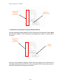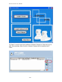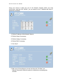
1
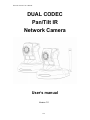
Network Camera User’s Manual
DUAL CODEC
Pan/Tilt IR
Network Camera
User’s manual
Version 1.0
1/53
Network Camera User’s Manual
Table of Contents
Overview...............................................................................................................3
Package Contents.................................................................................................4
Connections..........................................................................................................5
Hardware description.....................................................................................5
Hardware Installation ............................................................................................7
Connect to the Network Camera...........................................................................9
Install the IP Finder program..........................................................................9
Install the Camera behind a NAT Router.............................................................12
Initial Access to the Network Camera .................................................................16
Primary user’s capability .....................................................................................21
Main Screen with Camera View...................................................................21
Definitions in Configuration .................................................................................25
System parameters.............................................................................................26
Security...............................................................................................................27
Network...............................................................................................................28
Network type................................................................................................28
HTTP ...........................................................................................................29
Stream server ..............................................................................................29
RTSP Streaming ..........................................................................................29
WLAN Configuration (Wireless Model Only) .......................................................30
IP configuration............................................................................................32
DDNS..................................................................................................................33
Stream ................................................................................................................34
Video...................................................................................................................35
Audio...................................................................................................................37
Camera control ...................................................................................................38
Camera control area ....................................................................................38
Preset function area.....................................................................................38
Email and FTP ....................................................................................................40
Motion Detection .................................................................................................42
Application ..........................................................................................................43
IP notification ......................................................................................................46
System log ..........................................................................................................47
Status..................................................................................................................48
Maintenance .......................................................................................................49
Appendix.............................................................................................................50
A. Troubleshooting & Frequently Asked Questions......................................50
B. Technical specifications ...........................................................................53
2/53
Network Camera User’s Manual
DUAL CODEC Pan/Tilt IR Network Camera
Overview
Law in your country may prohibit the use of surveillance devices. The Network Camera
is not only a high-performance web-ready camera but also can be part of a flexible
surveillance system. It is the user’s responsibility to ensure that the operation of such
devices is legal before installing this unit for its intended use.
It is important to first verify that all contents received are complete according to the list in
the "Package Contents" chapter. Take notice of the warnings in “Quick installation guide”
before the Network Camera is installed, then carefully read and follow the instructions in
the “Installation” chapter to avoid damages due to faulty assembly and installation. This
also ensures the product is used properly as intended.
The Network Camera is accessible via the LAN or Internet connection. Connect your
Network Camera directly to a computer network or DSL modem, and with a standard
Web browser you get instant, on demand video streams. Within minutes you can set up
the Network Camera to capture a video sequence to a PC. Live video image can be
uploaded to a website for the world to see or made available only to select users on the
network.
The Network Camera is a network device and its use should be straightforward for those
who have basic network knowledge.
The Network Camera is designed for various applications including video sharing,
general security/surveillance, etc. The “How to Use” chapter suggests ways to best
utilize the Network Camera and ensure proper operations.
Minimum System Requirement
DUAL CODEC Pan/Tilt IR Network Camera
Network Environment
LAN
10/100M Ethernet
Monitoring System Recommended for Internet Explorer
System Hardware
· CPU: Pentium 4, 2GHz or above
· Memory Size : 128 MB (256 MB or above Recommended )
· VGA card resolution : 1024 x 768 or above
System Requirement for Viewer & Recorder Application
Support OS
Windows 2000 , XP, Vista
System Hardware
1-4 cameras surveillance application
· CPU: Pentium 4, 2GHz or above
· Memory Size : 256 MB or above
· VGA card resolution : 1024 x 768 or above
3/53
Network Camera User’s Manual
Package Contents
If any of the above items are missing, please contact your dealer immediately.
Network Camera (Wired or Wireless)
Software CD
Power adapter
Quick installation guide
Bracket
Antenna (For Wireless Model
Only)
Note: Using a power supply with a different voltage than the one included with the
Network Camera will cause damage and void the warranty for this product.
4/53
Network Camera User’s Manual
Connections
Hardware description
1. DC Power Jack
The DC power input jack is located on the rear of Network Camera’s. The input power is
12VDC. Note that supply the power to the Network Camera with standard power adapter
included in package. Otherwise, the improper power adapter may damage the unit and
result in danger.
2. LAN Socket
Beside the DC power Jack, the LAN socket is an RJ-45 connector for connections to
10Base-T or 100Base-TX Fast Ethernet cabling. Please use Category 5 “straight
through” cable to connect the Network Camera to an Ethernet network switch or hub.
3. Antenna (Wireless model only)
4. Microphone
The Network Camera’s has built-in an internal microphone. This microphone is also
hidden in the pinhole located on the head of camera.
5. Front LEDs
Red LED indicate power, red LED will turn on always after plug-in power.
Orange LED indicate audio, orange LED will turn off if audio is set as mute.
Green LED indicate networking, green LED will blink every second after getting ip
address.
Upon powering up, three of front LEDs will become lighted then the camera will do
self-rotation. During the self-rotation, red LED will be on and the network camera is
standby for getting ip address.
6. Infrared LEDs and Light sensor
There are six Infrared (IR) LEDs and a light sensor in front of the head of camera for
night vision purpose. The IR LEDs will auto or manual turn on when the camera is in the
dark environment.
7. Factory Default Reset
This button is hidden in the pinhole under then Network Camera’s bottom. Please refer
to the Appendix A in this manual for more information.
5/53
Network Camera User’s Manual
LAN Socket
DC power Jack
Infrared LEDs and
Light sensor
Antenna,
Wireless
model only
Microphone
Front LEDs
Factory default
reset button
6/53
Network Camera User’s Manual
Hardware Installation
1. Attach the Network Camera with the included stand
2. Place the Camera on the table or fix it onto ceiling or wall
Use screws to fix the Network Camera onto the ceiling or wall. You could also put the
Network Camera on the table directly.
Fixed it by
Screws
3. Plug a RJ-45 ethernet cable into the Network Camera
Connect an Ethernet cable to the LAN socket located on the rear of Network Camera’s
and attach it to the network.
7/53
Network Camera User’s Manual
Antenna for
Wireless
model only
Ethernet
Cable Socket
4. Connect the external power supply to Network Camera
Connect the attached power adapter to the DC power jack of the Network Camera. Note:
Use the power adapter, 12VDC, included in the package and connect it to wall outlet for
AC power.
Antenna for
Wireless
model only
Power
Socket
Once you have installed the Network Camera well and powered on, the camera will do
self-rotation and then the red LED will turn on and green LED will flash every second. It
means that the system is booting up successfully.
8/53
Network Camera User’s Manual
Connect to the Network Camera
Install the IP Finder program
When you installed your Network camera on your LAN environment, you may install “IP
Finder” to discover Network camera’s IP address. The Administrator must place the
product software CD into the CD-ROM drive of the PC running in Microsoft Windows. An
auto-run program will pop up (If the program is not on auto-run, go to the root directory
of the software CD and click on “autorun.exe”).
Click on “Software Utility” item, after the window contents changed, click on “Install IP
Finder” to run “IP Finder” program.
9/53
Network Camera User’s Manual
“IP Finder” is used to search the ip address of Network Cameras or Video servers on a
LAN. After searching, Video Servers or Network Cameras will be located by the IP
Finder.
10/53
Network Camera User’s Manual
Using your mouse to select any one of the Network Cameras within your LAN
environment, and then click “Wizard”, you can search out its IP address and other IP
parameters as follows:
1. Edit the IP address of this Network Camera.
2. Edit the Subnet if necessary.
3. Edit the Getway if necessary.
4. Edit the DNS if necessary.
5. Click “Next”.
6. Make sure all the settings are correct and then click “Re-Start”, the
Network Camera will restart the system to validate the new setting after
seconds.
11/53
Network Camera User’s Manual
Install the Camera behind a NAT Router
The Network Camera can be used with a router. This section explains how to view the
camera from either the Internet or from inside your LAN. If the Network Camera was
installed on the LAN with a router, then it can get a dynamic IP address from the DHCP
server. However, if the Network Camera wants to be accessed from the WAN, its IP
address needs to be setup as fixed IP, also the Virtual Server function of router needs to
be setup.
Installing a Network Camera with a router on your network is an easy 3–step procedure:
(1) Assign a local IP Address to your Network Camera
(2) Access the Router with Your Web browser
(3) Open Virtual Server Ports for Your Router (Enable Remote Viewing)
(1) Assign a local fixed IP address to your Network Camera
Follow the steps in the Quick Installation Guide to configure the Network Camera. The
camera will be assigned a local fixed IP Address that allows it to be recognized by the
router. Manually setup the Network Camera as fixed IP, for example, such as
192.168.0.20.
(2) Access the Router with Your Web browser
The following steps generally apply to any router that you have on your network. The
D-Link DI-624 is used as an example to clarify the configuration process. Configure the
initial settings of the DI-624 by following the steps outlined in the DI-624 Quick
Installation Guide.
If you have cable or DSL service, you will most likely have a dynamically assigned WAN
IP Address. ‘Dynamic’ means that your router’s WAN IP address can change from time
to time depending on your ISP. A dynamic WAN IP Address identifies your router on the
public network and allows it to access the Internet. To find out what your router’s WAN
IP Address is, go to the Status screen on your router and locate the WAN information
for your router. As shown on the following page the WAN IP Address will be listed. This
will be the address that you will need to type in your web browser to view your camera
over the Internet. Be sure to uncheck the Reset IP address at next boot button at the
top of the screen after modifying the IP address. Failure to do so will reset the IP
address when you restart your computer.
12/53
Network Camera User’s Manual
Your WAN IP Address will be listed here.
Note: Because a dynamic WAN IP can change from time to time depending on your
ISP, you may want to obtain a Static IP address from your ISP. A Static IP address is a
fixed IP address that will not change over time and will be more convenient for you to
use to access your camera from a remote location. If you could not get a Static IP
address from your ISP, the DDNS is a solution alternatively. Please refer to Appendix G
for more information.
(3) Open Virtual Server Ports to enable remote image viewing
The firewall security features built into the DI-624 and most routers prevent users from
accessing the video from the Network Camera over the Internet. The router connects to
the Internet over a series of numbered ports. The ports normally used by the Network
Camera are blocked from access over the Internet. Therefore, these ports need to be
made accessible over the Internet. This is accomplished using the Virtual Server
function on the router. The Virtual Server ports used by the camera must be opened
through the router for remote access to your camera. Virtual Server is accessed by
clicking on the Advanced tab of the router screen.
13/53
Network Camera User’s Manual
Follow these steps to configure your router’s Virtual Server settings
(1) Click Enabled.
(2) Enter a unique name for each entry.
(3) Select Both under Protocol Type (TCP and UDP)
(4) Enter your camera’s local IP Address (e.g., 192.168.0.20, for example) in the
Private IP field.
(5) If you are using the default camera port settings, enter 80 into the Public and
Private Port section, click Apply.
(6) Scheduling should be set to Always so that the camera images can be
accessed at any time.
A check mark appearing before the entry name will indicate that the ports are enabled.
Important: Some ISPs block access to port 80. Be sure to check with your ISP so that
you can open the appropriate ports accordingly. Some ISPs block traffic on commonly
used ports to conserve bandwidth. If your ISP does not pass traffic on port 80, you will
need to change the port the camera uses from 80 to something else, such as 8080. Not
all routers are the same, so refer to your user manual for specific instructions on how to
open ports.
14/53
Network Camera User’s Manual
z
z
Enter valid ports in the Virtual Server section of your router
Please make sure to check the box on this line to enable settings
z
Then the Network Camera can be access from WAN by the router’s WAN IP
Address.
z
By now, you have finished your entire PC configuration for Network Camera.
15/53
Network Camera User’s Manual
Initial Access to the Network Camera
(1) For the initial access to the Network Camera in Windows, the web browser may
prompt for permission to install a new plug-in for the Network Camera. Permission
request depends on the Internet security settings of the user’s PC or notebook. If the
highest security level is set, the computer may prohibit any installation and execution
attempt. This plug-in has been registered for certificate and is used to display the
video in the browser. Users may click on
to proceed. If the web browser
does not allow the user to continue to install, check the Internet security option as
below steps.
Choose ToolsÆInternet OptionsÆSecurityÆCustom level
ÆCheck “Enable” or “Prompt” at Download unsigned ActiveX controls setting
ÆClick ok and then refresh the webÆClick “Install” and “Run” ActiveX controls
16/53
Network Camera User’s Manual
17/53
Network Camera User’s Manual
18/53
Network Camera User’s Manual
(2) The default Administrator’s password is blank and the Network Camera initially will
not ask for any password. The Administrator should immediately implement a new
password as a matter of prudent security practice. Once the Administrator’s
password is saved, the Network Camera will ask for the user’s name and password
before each access.
(3) The video will be displayed.
19/53
Network Camera User’s Manual
Note: The user name for the Administrator is permanently assigned as “root”.
Once the password is changed, the browser will display an authentication window
to ask for the new password. Once the password is set, there is no provision to
recover the Administrator’s password. The only option is to restore to the original
factory default settings.
20/53
Network Camera User’s Manual
Primary user’s capability
Main Screen with Camera View
The main page has three parts:
Configuration functions: The camera can be configured using these user interfaces.
Camera View: What can be seen through the camera.
Pan/Tilt control buttons: These buttons provide the direction to control the pan and
tile of camera.
Click the configuration in the bottom of left column to link to the configuration page.
Configuration functions:
“Intranet Mode” User can select this button to choose the better video & links quality
“Internet Mode” User can select this button to choose the better video & links uality
“Stream Selection” Click the down arrow to choose the quality of image (VGA
640*480 , QVGA 320*240 , QQVGA 160*120 )
“Configuration” Please note that only the administrator can access it.
Camera view:
On the top of image shows the connecting type of the Network Camera and the current
date/time.
The camera view also provides users to select a specific area (as the right image).
21/53
Network Camera User’s Manual
Using mouse to click the small window on the image to select the size of object.
22/53
Network Camera User’s Manual
View capabilities:
Users can select the icon of the video that she/he wants to function.
“Audio” Click on this button can adjust the audio volume & Latency .
“Image” Click on this button can adjust the image Brightness & Contrast.
“Digital zoom” The checkbox selection allows users to open a digital zoom, and to
control window to enlarge specified area in the camera view.
“Scaling” Click on this button to select camera view zoom in/out.
“Snapshot Record” Use this function, you can record snapshots or video in your PC
by IE browser directly. The files format will be in JPG or asf.
“Schedule” This provides basic schedule recording setting to make schedule
recordings through IE browser.
Note: You have to connect to the camera on home page all the time while doing IE
recording. Shutting down IE or accessing to Configuration settings will stop
recording function. If you would like to do detail recording settings or
multi-channel recording, please install bundled 16CH recording software in CD.
“Statistics ” Click on this button to show the connection type.
“About” Click on this button to show control version.
23/53
Network Camera User’s Manual
Pan/Tilt control buttons:
The direction buttons are for “Left”, “Right”, “Up”, “Down”, “Cross Angles”, and
“Home”.
Camera returns to center when click “Home” button
“Go to” Once the Administrator has set the present positions; users can click down
arrow to choose one position.
“Pan Angle” User can choose the angles when the camera moves left and right each
time.
“Tilt Angle” User can choose the angles when the camera moves up and down each
time.
“Pan” The camera will move from right side to left side continuously when click the
button.
“Patrol” The button directs the camera to patrol among the preset positions in the
patrol list, which can be modified on the “Camera control page”. The cycle of patrol is
from 0 to 50.
“Stop” User can stop the movement of camera, such as Auto pan, Auto Patrol, and etc.,
by clicking the button.
24/53
Network Camera User’s Manual
Definitions in Configuration
Please note that only the Administrator can access the system configuration. Each
category in the left column will be explained on the following pages.
25/53
Network Camera User’s Manual
System parameters
“Host name” The text displays the title on the top of the main page.
“Description” The text displays the description of the camera.
“Turn off the LED indicator” Check this option to turn off the LED indicators. It can
prevent the camera’s operation being noticed.
“Language Selection” Click this to select language English / Chinese of the Network
Camera.
“Daylight saving” Summertime; It will be one hour ahead.
“Keep current date and time” Click on this to keep the current date and time of the
Network Camera. An internal real-time clock maintains the date and time even when the
power of the system is turned off.
“Sync with computer time” Synchronize the date and time in the Network Camera
according to the local computer.
“Manual” Adjust the date and time by the Administrator.
“Automatic” Synchronize the time according NTP server over the Internet whenever
the Network Camera is switched on. It fails if the assigned time-server cannot be found.
》“NTP server” Assign the IP address or domain name of the time-server. Leaving the
text box blank connects the Network Camera to the default time-servers.
》“Time zone” Choose a time zone from the down arrow
》“Update interval” Select 0 ~ 23 hours update with the time on the NTP server.
Remember to click on “Save” to immediately validate the changes. Otherwise, the
correct time will not be synchronized.
26/53
Network Camera User’s Manual
Security
1
2
3
Protect Network Camera by passwords
The Network Camera is shipped without any password by default. That means everyone
can access the Network Camera including the configuration as long as the IP address is
known. It is necessary to assign a password if the Network Camera for everyone who
wants to access the camera. Type a new word twice in “1” area to enable protection.
This password is used to identify the administrator. Then add an accounts in user name
and type password for your friends in “2” area. Network Camera can provide twenty
accounts for your valuable customers or friends. You may delete some users from “3”
area.
“Root password” Change the Administrator’s password by typing in the new
password identically in both text boxes. The typed entries will be displayed as asterisks
for security purposes. After pressing “Save”, the web browser will ask the Administrator
for the new password to access.
“Add user” Type the new user's name and password, then press “Add” to insert the
new entry. The new user will be displayed in the user name list. This is up to 20 user
accounts.
“Manager user” Click the down arrow to choose a user’s name and press “Delete” to
complete.
27/53
Network Camera User’s Manual
Network
Any changes made on this page will restart the system in order to validate the changes.
Make sure every field is entered correctly before clicking on “Save”
Network type
“LAN” & “PPPoE”
The default type is LAN. Select PPPoE if using ADSL
"Get IP address automatically" & “Use fixed IP address”
The default status is “Get IP address automatically”. This could be tedious to perform
software installation whenever the Network Camera starts. Therefore, once the network
is set, especially for the IP address should be entered correctly. Select “Use fixed IP
address” then the Network Camera will skip installation. The Network Camera will
automatically restart and operate normally after a power outage. User can run IP installer
28/53
Network Camera User’s Manual
to check the IP address assigned to the Network Camera if the IP address is forgotten,
or user can use the UPnP function provided by the Network Camera (MS Windows XP
provides UPnP function at My Network Place).
》“IP address” This is necessary for network identification.
》“Subnet mask” This is used to determine if the destination is in the same subnet.
The default value is “255.255.255.0”.
》“Default router” This is a gateway used to forward frames to destinations in a
different subnet. Invalid router setting will fail the transmission to destinations in different
subnet.
》“Primary DNS” The primary domain name server that translates hostnames into IP
addresses.
》“Secondary DNS” Secondary domain name server backups the Primary DNS.
》“Enable UPnP” Enable UPnP ability.
“PPPoE” If using the PPPoE interface, should fill the following settings from ISP
》“User name” The login name of PPPoE account
》“Password” The password of PPPoE account
》“Confirm password” Input password again for confirmation
HTTP
“Http port” This can be typed besides the default Port 80. Once the port is changed,
the users must make sure the change for the connection is successful. For instance,
when the Administrator changes the HTTP port of the Network Camera which IP address
is 192.168.0.20 from 80 or 1025 to 65535, the users must type in the web browser
“http://192.168.0.20:8080” instead of “http://192.168.0.20”.
Stream server
“Stream port” Stream port can be typed besides the default Port 53
RTSP Streaming
The RTSP streaming currently supports video only, audio only, and audio/video. To use
the audio stream, type the url as “rtsp://61.30.125.43:554/audio”. To use the video
stream, type the url as “rtsp://61.30.125.43:554/videoN”. To use the audio/video stream,
type the url as “rtsp://61.30.125.43:554/avN”. The valid value for “N” is 2 and 3. When
the stream contains audio data, the audio codec at camera must select AMR.
“RTSP Port” RTSP port can be typed besides the default Port 554
29/53
Network Camera User’s Manual
WLAN Configuration (Wireless Model Only)
WLAN configuration (Wireless model only)
“SSID” (Service Set Identifier), it is to identify a wireless network. Access Points and
wireless clients attempting to connect to a specific WLAN (Wireless Local Area Network)
must use the same SSID. The default setting is default. Note: The maximum length of
SSID is 32 single-byte characters and SSID can’t be any of “, <, > and space character.
“Wireless mode” Click the down arrow to select one from options:
1. “Infrastructure” The Network Camera connects to the WLAN via an Access Point.
(The default setting)
》“TX rate” This field is for selecting the maximum transmission rate on the network.
The default setting is “auto”. It means the Network Camera will try to connect to the other
wireless device with highest transmitting rate.
》 “Security” Select the data encrypt method
》 “None” – No data encryption.
》 “WEP” – allows communication only with other devices, which are with identical
WEP settings.
identical WEP settings.
30/53
Network Camera User’s Manual
》 “WPA-PSK” – Use WPA pre-shared key.
》 “WPA2-PSK” – Use WPA2 pre-shared key.
》 “Auth Mode” Choosing one of the following modes, (Default original setting is
OPEN).
》 “Open” – communicates the key across the network.
》 “Shared” – allows communication only with other devices, which are with
identical WEP settings.
》 “Key length” The administrator can select the key length of 64 or 128 bits. 64bits is
the default setting.
》 “Key format” Hexadecimal or ASCII. “HEX” is the default setting.
》 “HEX” digits consist of the numbers 0~9 and the letters A-F.
》 “ASCII” is a code for representing English letters as numbers from 0-127 except
“, <, > and space characters that are reserved.
》 “Network Key” Entering a key in either hexadecimal or ASCII format. When
selecting different key length, acceptable input length is listed as following:
64 bits key length: 10 Hex digits or 5 characters.
128 bites key length: 26 Hex digits or 13 characters.
Note: When 22(“), 3C(<) or 3E(>) are input in network key, the key format can’t be
changed to ASCII format.
》 “Algorithm” Choosing one of the following algorithm for WPA-PSK modes
》 “TKIP”
》 “AES”
》 “Pre-shared Key” Entering a key in ASCII format. The length of the key is 8 ~ 63
2. “Ad-Hoc” Make the Network Camera connect directly to a host equipped with a
wireless adapter in a peer-to-peer environment.
》 “Channel” Under infrastructure mode, the channel will be selected automatically to
match the channel setting for the selected Access Point. Under Ad-Hoc mode, the
channel must be manually set to the same channel for each wireless adapter. The
default channel setting depends on the installed region.
》 “TX rate” This field is for selecting the maximum transmission rate on the network.
The default setting is “auto”. It means the Network Camera will try to connect to the other
wireless device with highest transmitting rate.
》 “Security” Select the data encrypt method
》 “None” – No data encryption.
》 “WEP” – allows communication only with other devices, which are with identical
WEP settings.
》 “Auth Mode” Choosing one of the following modes, (Open is the default setting).
》 “Open” – communicates the key across the network.
》 “Shared” – allows communication only with other devices, which are with
identical WEP settings.
》 “Key length” The administrator can select the key length of 64 or 128 bits. 64bits is
the default setting.
》 “Key format” Hexadecimal or ASCII. “HEX” is the default setting.
》 “HEX” digits consist of the numbers 0~9 and the letters A-F.
31/53
Network Camera User’s Manual
》 “ASCII” is a code for representing English letters as numbers from 0-127 except
“, <, > and space characters that are reserved.
》 “Default key/Network Key” Entering a key in either hexadecimal or ASCII format.
When selecting different key length, acceptable input length is listed as following:
64 bits key length: 10 Hex digits or 5 characters.
128 bites key length: 26 Hex digits or 13 characters.
Note: When 22(“), 3C(<) or 3E(>) are input in network key, the key format can’t be
changed to ASCII format.
IP configuration
"Get IP address automatically" & “Use fixed IP address”
The default status is “Get IP address automatically”. This can be tedious to perform
software installation whenever the Network Camera starts. Therefore, once the network
is started, especially for the IP address should be entered correctly. Select “Use fixed IP
address” then the Network Camera will skip installation. The Network Camera can
automatically restart and operate normally after a power outage. User can run IP installer
to check the IP address assigned to the Network Camera if the IP address is forgotten,
or user can use the UPnP function provided by the Network Camera (MS Windows XP
provides UPnP function at My Network Place).
》 “ IP address” This is necessary for network identification.
》“Subnet mask” This is used to determine if the destination is in the same subnet. The
default value is “255.255.255.0”.
》 “Default router” This is the gateway used to forward frames to destinations in a
different subnet. Invalid router setting will fail the transmission to destinations in
different subnet.
》 “Primary DNS” The primary domain name server translates hostnames into IP
addresses.
》 “Secondary DNS” Secondary domain name server backups the Primary DNS.
NOTE: Some invalid settings may cause the system failing to respond. Change the
configuration only if necessary and consult with your network supervisor or
experienced users for correct settings.
32/53
Network Camera User’s Manual
DDNS
DDNS: Dynamic domain name service
“Enable DDNS” This option turns on the DDNS function.
“Provider” The provider list contains hosts that provide DDNS services. Please
connect to the service provider’s website to make sure the service charges.
“Host Name” If the User wants to use DDNS service, this field must be filled. Please
input the hostname that is registered in the DDNS server.
“User name” The Username or E-mail field is necessary for logging in the DDNS
server or notify the User of the new IP address.
Note: when this field is input as “User name”, the following field must be input as
“Password”.
“Password” Please input the password or key to get the DDNS service.
“Save” Click on this button to save current settings for the DDNS service.
33/53
Network Camera User’s Manual
Stream
Stream Settings
“Select internet connection mode” This option turns on the Internet Mode function.
“Stream type” The Network Camera supports two kind of video compression mode:
MPEG4 or MJPEG. User can choose one of these compression modes based on
requirement or application.
“Quality” User can adjust the video quality from 24kbps to 2048kbps for MPEG4
stream. For MJPEG stream, user can select from lowest quality to get best quality
according to their requirement.
“Max Frame Rate” User can set the desired max frame rate to match the limitation of
bandwidth or other requirement.
“Message Enable” Select information will be shown on live video.
“Save” Click on this button to save current settings
34/53
Network Camera User’s Manual
Video
Video setting
“Power freq.” Select 50 Hz or 60Hz power line frequency.
※The fluorescent light will flash according to the power line frequency that
depends on local utility. Change the frequency setting to eliminate uncomfortable
flash image when the light source is only fluorescent light.
“Color” Select color or monochrome video display.
“Video orientation” The orientation of video
》”Flip” Vertically rotate the video.
》”Mirror” Horizontally rotate the video.
Check the two options if the Network Camera is installed upside down.
“White balance”
》”Auto” Adjust the white balance automatically.
》”Hold”: Fix the white balance.
“Exposure” Adjust the value for best exposure time.
》”Auto” Adjust the exposure automatically.
》”Hold”: Fix the exposure.
“Infrared LED Control” IR led for Day and Night (Option). User can turn on/off or
scheduling the built-in IR led. This function is very useful under low illumination
environment.
》”Auto” Turn on IR led automatically.
》”Manual” Turn on/off the IR led manually.
》”Turn on” Turn on led
》”Turn off” Turn off led
”Dark mode” The video quality will be improved when the camera is in low lux
environment.
》”Disable dark mode” Disable dark mode.
》”Enable dark mode” Enable dark mode.
“Save” Click on this button to save current settings.
35/53
Network Camera User’s Manual
36/53
Network Camera User’s Manual
Audio
Audio settings
“Mute” Audio mute.
“Mic Volume” Adjust microphone volume.
“Audio type” Select audio codec
》” G.726”
》”bit rate” 16/24/32/40 Kbps
》“AMR”
》”bit rate” 4750/5150/5900/6700/7400/7950/10200/12000
“Save” Click on this button to save current settings.
37/53
Network Camera User’s Manual
Camera control
On the Camera Control page, there are two main function control areas:
Camera control area
The pan and tilt functions can be controlled with these buttons. The “Left” button
controls the camera to the left; the “Right”, “Up”, and “Down” buttons control the
camera accordingly.
“UL”, ”UR”, ”LL” and “LR“ buttons control the camera to an oblique angle. And
“Home” button controls the camera to the center.
“Pan angle” This sets the range of the horizontal movement of the camera. The larger
value is setting, the larger movement of “Left” or “Right” is performing by the camera.
“Tilt angle” This sets the range of the vertical movement of the camera. The larger
value is setting, the larger movement of “Up” or “Down” is performing by the camera.
“Patrol cycle” It is the cycle of patrol function.
“Auto pan speed” This defines the speed of auto panning. The larger value is setting,
the faster speed will run by the camera.
“Auto patrol speed” This defines the speed of auto patrol. The larger value is setting,
the faster speed will run by the camera.
Preset function area
”Current position” If the User wants to save the current view as a preset location,
enter a name to each of the current video view on “Current position” and click on the
“Add” button. The camera allows for 20 preset locations.
”Preset position” This keeps a list for preset positions. Clicking on the “Delete” button
will remove the current selected position from the preset list.
“Set as home” Click on the button will set the current aimed position as home of the
Network Camera. Each time the Network Camera reboots or finishes calibration, it will
automatically aim to the defined home position.
“Default home” Restore home position to original default’s home by clicking on this
button.
”Dwelling time (sec)” The stop time of each preset location during auto patrol of the
Network Camera.
”Patrol selection” After the User has saved a list of preset positions, the “Preset
locations” box will also keep a list of the preset positions. And once the “Select”
button is clicked, the “Selected location” box will keep a list of the patrol stops. The
“Remove” button removes the preset position from the patrol stops. The “UP” and
“DOWN” buttons adjust the order of the patrol stops. Several preset positions can be
added to the patrol stops. The camera can accept up to 25 patrol positions.
“Save” The button is valid for “Dwelling time” and “Patrol selections”. In other words,
after changing these settings, and the “Save” button is not clicked, the new setting of
the camera will not take effect.
38/53
Network Camera User’s Manual
Camera control area
Preset function area
39/53
Network Camera User’s Manual
Email and FTP
Email
When the SMTP server supports SMTP authentication, users need to give the valid user
name and password to send email via the server.
“Sender email address” It is the email address of the sender.
“Email subject” Input Suitable Email Title.
“Email body” Input Suitable Email Content.
There are two external mail server can be configured: primary and secondary email
server. The network camera will use primary server as default setting, and use
secondary server when primary server is unreachable.
“Server address” The domain name or IP address of the external email server.
“User name” This grants user name on the external email server.
“Password” This grants password on the external email server.
“Recipient email address” The email address of the recipients for snapshots or
recording files.
FTP
There are two external FTP server can be configured: primary and secondary FTP
server. The network camera will use primary server as default setting, and use
secondary server when primary server is unreachable.
Type the FTP server name or the IP address of the FTP server to upload still images and
video file
“Server address” The domain name or the IP address of the external FTP server. The
following user settings must be correctly configured for remote access.
“FTP server port” This can be typed besides the default port 21. The user can
change this value from 1025 to 65535.
“User name” Granted user name on the external FTP server.
“Password” Granted password on the external FTP server.
“Remote folder name” Granted folder on the external FTP server. The string must
conform to that of the external FTP server. Some FTP servers cannot accept preceding
slash symbol before the path without virtual path mapping. Refer to the instructions for
the external FTP server for details. The folder privilege must be open for upload.
“Save” Click on this button to save current settings.
40/53
Network Camera User’s Manual
41/53
Network Camera User’s Manual
Motion Detection
“Enable motion detection” You can enable or disable motion detection function
“Windows 1 ~ Windows 4” Click on this option to add a window. Up to four windows
can exist simultaneously. Use the mouse to drag the border of the window to resize or
click the title bar to move.
“Threshold” This sets the space ratio of moving objects in the monitoring window.
“Power” It is the strength of the motion detection.
“Sensitivity” This sets the endurable difference between two sequential images.
Higher sensitivity and small threshold will allow easier motion detection.
Note: 1. If select internet mode, the overall performance of Network Camera will be
degraded, and the frame rate may be reduced.
2. When alarm was enabled, user can send the captured images to the pre-set E-Mail or
FTP server.
A small detection window will
be pop-up as soon as you
check Window1~Window4.
42/53
You can enlarge the pop-up
window and move it to the area
where you want to detect.
Network Camera User’s Manual
Application
Method
“Enable notification” Enable/Disable notification application.
“Enable snapshot” Enable/Disable snapshot application.
“Enable video clip” Enable/Disable video clip application.
Weekly schedule
“Sun”/”Mon”/”Tue”/”Wed”/”Thu”/”Fri”/“Sat” Select the days of the week to
perform the application.
Time
Select “Always” or input the time interval.
File name prefix
“Snapshot” The prefix name should be added on the file name of the snapshot
images.
“Video clip” The prefix name should be added on the file name of the Video clip.
Trigger
“Motion detection” Sends out the notification/snapshot/video while motion detection.
“Delay second(s) before detecting next motion” Set the time delay before
restarting to check on the triggering condition when the current condition is triggered.
Sends files by
“Email” Selects sending files by email. The files will be attached in the email.
“FTP” The files will be uploaded to the external FTP server with the file name defined in
the next option. This can also be used to refresh the files stored in the external web
server to build creative homepages.
》“FTP put snapshots with date and time suffix” This option sets up the snapshot
capture date and time, which can be used to easily differentiate the snapshot file names
in the sequential operation. For instance, “prefix -20080809-060905.jpg” means the
JPEG image was captured in the year 2008,August the 9nd, at 6 o’clock, 9 minute, and 5
second. If this suffix is omitted, the file named “xxx.jpg” on the external FTP server will
be refreshed at the specified interval. (Note: When prefix is empty, a serial number
will be generated continuously as “xxx”. And if prefix is specified, “xxx” will be
fixed as prefix)
》“FTP put video clip with date and time suffix” This option sets up the video clip
capture date and time, which can be used to easily differentiate the snapshot file names
in the sequential operation. For instance, “prefix-20080809-060905.asf” means the video
43/53
Network Camera User’s Manual
clip was captured in the year 2008, August the 9nd, at 6 o’clock, 9 minute, and 5 second.
If this suffix is omitted, the file named “xxx.asf” on the external FTP server will be
refreshed at the specified interval. (Note: When prefix is empty, a serial number will
be generated continuously as “xxx”. And if prefix is specified, “xxx” will be fixed
as prefix)
“Samba network disk” The files will be uploaded to the samba network disk.
44/53
Network Camera User’s Manual
Samba
“Enable Samba” Enable/Disable file uploaded to the Samba network disk.
“Samba/NAS server” The IP address of the Samba network disk.
“Domain” The domain name of the Samba network disk.
“User name” This granted user name on the Samba network disk.
“Password” This granted password on the Samba network disk.
“Save path” The files in the Samba network disk storage path.
45/53
Network Camera User’s Manual
IP notification
“Enable notification” Enable/Disable IP address change notification application
“Sender email address” The email address of the sender.
“Server address” The domain name or IP address of the external email server.
“Email subject” It’s a unique number for each Network Camera for identification.
“User name” This granted user name on the external email server.
“Password” This granted password on the external email server.
“Recipient email address” The email address of the recipients IP address change
notification.
46/53
Network Camera User’s Manual
System log
The Network camera supports log the system messages on remote server. The protocol
is compliant to RFC 3164. If you have external Linux server with syslogd service, use “-r”
option to turn on the facility for receiving log from remote machine. Or you can use some
software on Windows that is compliant to RFC 3164.
Check “Enable remote log” and input the “IP address” and “port” number of the log
server to enable the remote log facility.
In the “Current log”, it displays the current system log file. The content of the log
provides useful information about configuration and connection after system boot- up.
47/53
Network Camera User’s Manual
Status
User can find a lot of information about the system such as MAC address, IP address,
firmware version, and so on. User also can get the number of current viewer of the
Network Camera here.
48/53
Network Camera User’s Manual
Maintenance
“Reboot system” The “Reboot” button will reboot the Network Camera. It’s useful
while the Network Camera got problem.
“Factory default” Click on Factory default button on the configuration page to restore
the factory default settings. Any changes made so far will be lost and the system will be
reset to the initial factory settings. The system will restart and require the installer
program to set up the network again.
“Calibrate” Recalibrate the home position to the default center to recover the tolerance
cased by some external forces. Please note that there is no confirming message box
after clicking on the “Calibrate” button, the Network Camera will calibrate immediately.
“Upgrade firmware” Select the firmware file and click upgrade button. Please be
aware that you should not turn off the power during updating the firmware and wait for
finish message.
Warning: The upgrade firmware procedure cannot be interrupted. If the power
and/or network connection are broken during the procedure, it might possibly
cause serious damage to the Network Camera.
Note: When upgrade firmware please wait for 90~180 seconds, and then you can
connect to Network Camera again. The system will restart and require the installer
program to set up the network again.
49/53
Network Camera User’s Manual
Appendix
A. Troubleshooting & Frequently Asked Questions
Q1: Status led does not light up.
A1: First, make sure that「Configuration>System>Turn off the LED indicator」is disabled.
If it is, check the item, and the led should light up. Second, if red led does not light up,
please check that the power adapter in the package is plugged correctly. Third, if orange
led does not light up, make sure if the microphone is mute. And last, if green led does
not light up, please check that category 5 UTP cable is plugged correctly.
If the problem is still not solved, please contact your dealer for further help.
Q2: What kind of Ethernet cable is used by network camera?
A2: The network Camera uses Category 5 UTP cable allowing 10 and/or 100 Base-T
networking.
Q3: The Network Camera will be installed and work if a firewall exists on
the network.?
A3: If the network camera is behind NAT, it must be to make sure http port(80)/video
stream port(53)/audio stream port(5001)/rtsp port(554) is port mapping with NAT.
Note: The firewall software at PC may block the transfer of network camera.
Please remove or stop the kind software.
Q4: What is the default name and password of administrator?
A4: The name is “root” and password is blank.
Q5: How can I find the network camera in the local area network?
A5: By using the PTCamFdr program or using UPnP to find it.
Q6: PTCamFdr program cannot find Network Camera in the local area
network at first time?
A6: Make sure the subnet of network camera is same as your PC. If the local area
network supports DHCP, the camera is “Get IP address automatically” in the “Network”
page default. If the local area network does not support DHCP, change your PC IP
address to “192.168.0.xxx”.
Q7: What is the maximum number of users access Network Camera
simultaneously?
A7: The maximum number of users is 10 for one video stream. At normal, there are
three streams at network camera (VGA/QVGA/QQVGA).
Q8: How can I restore the network camera to default value?
50/53
Network Camera User’s Manual
A8: Use a gem clip to press on the inside button until the led flashing. After three cycles
of the flashing, the network camera begins to restore default value. You can also press
the button “Factory” in “Maintenance” page to restore the default value.
Q9: I cannot play the recorded video file.
A9: Install the audio codec in the CD, and use the Windows Media Player 10 or later to
play the *.asf file recorded by the network camera.
Q10: Infrared led does not light up?
A10: Check「Configuration>Video>Infrared LED Control」 is “Auto” or “Manual》Turn
on”.
Q11: The network camera cannot focus accurately.
A11: (1) The lens is dirty or dust is attached. Clean the lens with lens cleaner. And then
adjust the camera focus manually.
(2) The image may be out of focus. If the object is too near, move the object away from
Network Camera.
Q12: The cover of network camera is warm. Is it normal?
A12: Network camera is a precision device. The internal material has the operational
temperature, and it is normal when user touch the cover feels warm. It is recommended
to put the network camera at aired place, and not put at any other device.
Q13: What is the scope of wireless network camera connecting AP?
A13: The scope of wireless connection is different form the environment. The possible
interference is (1) the direction of antenna (2) the material and architecture of building (3)
the temperature of environment (4) the position of the network camera.
Q14: The process of upgrade firmware abort.
A14: Contact your dealer for further help.
51/53
Network Camera User’s Manual
Q15: Cannot access the login page and other web pages of Network
Camera from Internet Explorer
A15:
• May be due to the network cable. Try correcting your network cable and configuration.
Test the network interface by connecting a local computer to the Network Camera via a
crossover cable.
• Make sure the Internet connection and setting is ok.
• Make sure enter the IP address of Internet Explorer is correct. If Network Camera has
a dynamic address, it may have changed since you last checked it.
• Network congestion may prevent the web page appearing quickly. Wait for a while.
The IP address and Subnet Mask of the PC and Network Camera must be in the same
class of the private IP address on the LAN.
• Make sure the http port used by the Network Camera, default=80, is forward to the
Network Camera’s private IP address.
• The port number assigned in your Network Camera might not be available via Internet.
Check your ISP for available port.
• The proxy server may prevent you from connecting directly to Network Camera, set up
not to use the proxy server.
• Confirm that Default Gateway address is correct.
• The router needs Port Forwarding feature. Refer to your router's manual for details.
• Packet Filtering of the router may prohibit access from an external network. Refer to
your router's manual for details.
• Access Network Camera from the Internet with the global IP address of the router and
port number of Network Camera.
• Some routers reject the global IP address to access Network Camera on the same
LAN. Access with the private IP address and correct port number of Network Camera.
• When you use DDNS, you need to set Default Gateway and DNS server address.
• If it’s not working after above procedure, reset Network Camera to default setting and
installed it again.
• Maybe the IP Address of the Network Camera is already being used by another device
or computer..
• If the problem is not solved, the Network Camera might be faulty. Contact your dealer
for further help.
52/53
Network Camera User’s Manual
B. Technical specifications
- System
- Camera specification
RAM: 64MB SDRAM
ROM: 8MB Flash ROM
1/6 inch color CMOS sensor, Resolution:
640x480 1.3Lux/F2.0
AGC, AWB, AEC
- Infrared Led
- Lens
Auto/manul mode
Daylight sensor, angle +/-65, wave length
400~700nm
Spectral band width 42nm, Peak emission
wavelength 850nm
Fixed focal with fine tuning, 4.0mm, F2.0
View angle 62 degree
- Protocol
- Video Resolution
TCP/IP, HTTP, SMTP, FTP, DDNS, UPnP,
Up to 30 frames at 160x120
Telnet, NTP, PPPoE, DNS, DHCP and RTSP Up to 30 frames at 320x240
Up to 30 frames at 640x480
- WLAN (Wireless Model Only)
- Audio
802.11b/g wireless LAN
AMR/G.726
Omni-directional Microphone
Frequency: 50 – 20000Hz
S/N ratio: more than 55dB
- Security
WEP/WPA-PSK/WPA2-PSK
- Algorithm supported
- Pan/Tilt angle
MPEG4/MJPEG dual codec for streaming
video
JPEG for still image
Support multi - direction movement
Pan : Range 355 degree, Tilt : Range 135
degree
- Physical
- Power
10 baseT or 100 baseT Fast Ethernet auto
negotiation
Input: 100-240VAC, 50/60Hz, 0.7A
Output: 12VDC, 1.5A
Consumption: Max 7 W
- EMI & Safety
- Dimension
CE, FCC
105 x 105 x 110 (mm)
- Operating Environment
- Weight
Temperature : 0 - 40℃
Humidity : 85% RH
NET. 355g (Wired Model)
NET. 365g (Wireless Model)
53/53