1
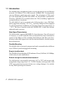
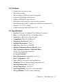
ADAM-6541
10/100Base-TX Ethernet to 100Base-FX
Multi-Mode Fiber Optic Converter
Copyright Notice
This document is copyrighted, 2003, by Advantech Co., Ltd. All rights are
reserved. Advantech Co., Ltd., reserves the right to make improvements to
the products described in this manual at any time without notice.
No part of this manual may be reproduced, copied, translated or transmitted
in any form or by any means without the prior written permission of
Advantech Co., Ltd. Information provided in this manual is intended to be
accurate and reliable. However, Advantech Co., Ltd. assumes no
responsibility for its use, nor for any infringements upon the rights of third
parties which may result from its use.
Part No. 2003654100
Printed Taiwan
ADAM-6541 manual
1st Edition
Feb. 2003
Advantech Customer Services
Each and every Advantech product is built to the most exacting specifications to ensure reliable performance in the unusual and demanding conditions typical of industrial environments. Whether your new Advantech
equipment is destined for the laboratory or the factory floor, you can be
assured that your product will provide the reliability and ease of operation
for which the name Advantech has come to be known.
Your satisfaction is our number one concern. Here is a guide to Advantech’s customer services. To ensure you get the full benefit of our services,
please follow the instructions below carefully.
Technical Support
We want you to get the maximum performance from your products. So if
you run into technical difficulties, we are here to help. For most frequently
asked questions you can easily find answers in your product documentation. These answers are normally a lot more detailed than the ones we can
give over the phone.
Please consult this manual first. If you still cannot find the answer, gather
all the information or questions that apply to your problem and, with the
product close at hand, call your dealer. Our dealers are well trained and
ready to give you the support you need to get the most from your Advantech products. In fact, most problems reported are minor and are able to be
easily solved over the phone.
In addition, free technical support is available from Advantech engineers
every business day. We are always ready to give advice on application
requirements or specific information on the installation and operation of
any of our products.
Product Warranty
Advantech warrants to you, the original purchaser, that each of its products will be free from defects in materials and workmanship for two years
from the date of purchase.
This warranty does not apply to any products which have been repaired or
altered by other than repair personnel authorized by Advantech, or which
have been subject to misuse, abuse, accident or improper installation. Advantech assumes no liability as a consequence of such events under the
terms of this Warranty.
Because of Advantech’s high quality-control standards and rigorous testing, most of our customers never need to use our repair service. If an
Advantech product ever does prove defective, it will be repaired or replaced at no charge during the warranty period. For out-of-warranty repairs, you will be billed according to the cost of replacement materials,
service time and freight. Please consult your dealer for more details.
If you think you have a defective product, follow these steps:
1.Collect all the information about the problem encountered (e.g. type of
PC, CPU speed, Advantech products used, other hardware and software
used etc.). Note anything abnormal and list any on-screen messages you
get when the problem occurs.
2.Call your dealer and describe the problem. Please have your manual,
product, and any helpful information readily available.
3.If your product is diagnosed as defective, you have to request an RMA
number. When requesting an RMA (Return Material Authorization) number, please access ADVANTECH’s RMA website: http://
www.advantech.com.tw/rma. If the web sever is shut down, please contact our office directly. You should fill in the “Problem Repair
Form”,describing in detail the application environment, configuration,
and problems encountered. Note that error descriptions such as “does
not work” and “failure” are so general that we are then required to apply
our internal standard repair process.
4.Carefully pack the defective product, a completely filled-out Repair and
Replacement Order Card and a photocopy of dated proof of purchase
(such as your sales receipt) in a shippable container. A product returned
without dated proof of purchase is not eligible for warranty service.
5.Write the RMA number visibly on the outside of the package and ship it
prepaid to your dealer.
ADAM-6541 manual
Contents
Chapter 1
Introduction .................................. 1-1
1.1 Introduction ...................................................................... 1-2
1.2 Features ............................................................................ 1-3
1.3 Specification .................................................................... 1-3
1.4 Package Checklist ........................................................... 1-4
1.5 Ordering Information ....................................................... 1-4
Chapter 2
Installation .................................... 1-5
2.1 Front / Rear View .............................................................. 1-6
2.2 Full / Half-Duplex Selection ............................................ 1-7
2.3 Connecting the Hardware ............................................... 1-8
2.3.1
Choosing a Location ................................................................... 1-8
2.4 Network Connection ...................................................... 1-10
2.4.1
2.4.2
2.4.3
2.4.4
Connection to the devices ........................................................ 1-10
Connection to other Hubs or Switch ........................................ 1-10
Connection to fiber network ..................................................... 1-11
Power Connection .................................................................... 1-11
Appendix A .................................................... 1-13
Figures
Figure
Figure
Figure
Figure
Figure
Figure
Figure
2-1
2-2
2-3
2-4
2-5
A-1
A-2
ADAM-6541-Front Panel ............................................................ 1-6
ADAM-6541-Rear Panel ............................................................. 1-7
Panel Mounting .......................................................................... 1-8
Din Rail Mounting ...................................................................... 1-9
Piggyback Stack ...................................................................... 1-10
RJ-45 Pin Assignment ............................................................. 1-14
EIA/TIA-568B ............................................................................ 1-14
ADAM-6541 manual
Tables
Table 2-1
ADAM-6541 LED Definition ....................................................... 1-6
ADAM-6541 manual
Chapter
1
Introduction
1.1 Introduction
The ADAM-6541 is an industrial grade converter designed to convert Ethernet
network (10/100Base-TX) to fiber network (100Base-FX). It transparently
converts Ethernet signals into optic signals. The advantages of Fiber optic
are wide bandwidth, anti-EMI and suitable for long-distance transmission.
Therefore, ADAM-6541 is an ideal solution for “fiber to building” application
in central offices or local sites.
The ADAM-6541 can be mounted in the following three ways: DIN Rail,
panel, piggyback mounting. +10~30 VDC operating voltages are also supplied
over the terminal block. In addition, the operating temperature ranges from -10
~ 70°C. The above functions make the ADAM-6541 a stable and reliable
industrial grade converter.
High-Speed Transmission
The ADAM-6541 supports MDI/MDI-X of auto detection. You will not need
to crossover. A switch controller that can automatically sense transmission
speed (10/100 Mbps) will be included. Both Ethernet and fiber ports have
memory buffers that support store-and-forward mechanism; it assures proper
data transmission.
Flexible Mounting
The ADAM-6541 is extremely compact and can be mounted in three different
ways: DIN rail, panel and piggyback mounting.
Easy to trouble-shoot
The ADAM-6541 provides three LED indicators: Power, Full/Link, 10/100Mbps,
which easily let you troubleshoot.
Robust enough for industrial environment
The ADAM-6541 can normally work from -10°C to 70°C and accepts wide
unregulated voltage range from +10 ~ 30 VDC. Besides, it also provides 3,000
VDC surge protection to protect it from over-voltage damages. It is suitable
for any harsh operating environment.
2 ADAM-6541 manual
1.2 Features
•
•
•
•
•
•
•
•
•
Compact size economizes space
Direct plug and play
Easy to mount on a DIN-rail, panel or piggyback
Supports full/half-duplex flow control
Supports MDI/MDI-X auto crossover
Embedded switch controller, supports auto-negotiation
Embedded memory buffer, supports store and forward transmission
Supports +10 ~ 30 VDC voltage
Supports operating temperature from -10° C ~ 70° C
1.3 Specification
•
•
•
•
•
•
•
•
•
•
•
•
•
•
•
•
•
Interface: Network: 10/100Base-TX & 100Base-FX standard
Port: 1 x 10/100 Mbps (RJ-45), 1 x 100 Mbps (Fiber)
Connector: 1 x RJ-45 & 1 x Fiber (SC type)
Compatibility: IEEE 802.3, IEEE 802.3u
Surge protection (Power): 3,000 VDC
Isolation (Ethernet port): 1,500 VRMS
LED: Power, Full/Link, 10/100 Mbps
Ethernet Transmission Distance (RJ-45): 100 m
Fiber Transmission Distance (Multi mode fiber):
50/125, 62.5/125 µm multi mode fiber
(1) 412 m for half duplex
(2) 2 km for full duplex
Power Requirement: unregulated 10 to 30 VDC
Power Consumption: 3 Watt
Case: ABS/PC with captive mounting hardware
Mounting: DIN-rail, panel mounting, piggyback stack
Operating Temperature: -10 to 70 °C
Storage Temperature: -20 to 80 °C
Operating Humidity: 20 to 95% (non-condensing)
Storage Humidity: 0 to 95% (non-condensing)
Chapter 1 Introduction 3
1.4 Package Checklist
•
•
•
•
ADAM-6541
ADAM-6541 Manual
NYLON Din-rail Mounting Adapter
SECC panel mounting bracket
1.5 Ordering Information
ADAM-6541: 10/100Base-TX Ethernet to 100Base-FX Multi-Mode Fiber
Optic Converter
4 ADAM-6541 manual
Chapter
2
Installation
In this chapter, you will be given an overview of the ADAM-6541 hardware
installation procedures.
2.1 Front / Rear View
There are six network LEDs located on the top panel of the ADAM-6541, each
with its own specific function.
LED
Color
Power
Full/Link (100Base-Fx)
100/10M (Ethernet)
Green
Power is On
Off
Power is Off
Green
Full-duplex
Orange
Half-duplex
Off
Not networking
Green
Link to 10Mbps
Orange
Link to 100Mbps
Off
Not networking
Table2-1 ADAM-6541 LED Definition
Figure 2-1 ADAM-6541-Front Panel
6 ADAM-6541 manual
Description
Figure 2-2 ADAM-6541-Rear Panel
2.2 Full / Half-Duplex Selection
There are two modes of data transmissions, full-duplex and half-duplex transmission. The data can be transmitted in both directions on a single carrier at
the same time when you select Full-duplex mode. But the data can only be
transmitted in one direction on a single carrier at the same time when you
select Half-duplex mode. You may select Full or half-duplex mode according to
your equipment requirement.
You can configure full or half-duplex ADAM-6541 via JP1 (located on the
top-left PCB.)
JP1
Description
Half-Duplex
Full-Duplex (Default)
NOTE:
Fiber Transmission Distance
(1) Half duplex: 412 m
(2) Full duplex: 2 km
Chapter 2 Installation 7
2.3 Connecting the Hardware
Next, we will explain how to find a proper location for your ADAM-6541,
connect to the network, hook up the power cable, and connect to the ADAM6541 Ethernet port.
2.3.1 Choosing a Location
Due to its versatility and innovative design, the ADAM-6541 can be:
• fixed to a panel mount
• fixed to a DIN Rail.
• Piggyback Stack
Panel Mounting
The ADAM-6541 can be attached to a wall using the included metal brackets.
Each bracket comes with four screws. First attach the brackets to the bottom
of the ADAM-6541, then screw each bracket to a wall.
Figure 2-3 Panel Mounting
8 ADAM-6541 manual
DIN Rail Mounting
You can mount the ADAM-6541 on a standard DIN Rail. First, using two
screws, attach the metal plate to the DIN Rail bracket. Because the screw
heads are beveled, the tops of the screws will be flush with the metal plate. Din
Rail Mounting Brackets-Orientation of Metal Plates: A more convenient way
is to screw the metal plate with the DIN rail bracket assembly to the bottom of
the server. Next, use the remaining screws to put the metal plate on the bottom
of the ADAM-6541.
Figure 2-4 Din Rail Mounting
Chapter 2 Installation 9
Piggyback Stack
ADAM-6541 can be stacked as seen in the figure below.
Figure2-5 Piggyback Stack
2.4 Network Connection
2.4.1 Connection to the devices
The ADAM-6541 consists of one fiber and one RJ-45 port.
Each of the converter’s twisted-pair ports can be used to connect a station or
other device. Use a straight-through twisted-pair cable with RJ-45 connectors
on both ends. The twisted-pair cable extended from a twisted-pair port is
called a “twisted-pair segment,” that can be up to 100 meters long. You can
connect any RJ-45 (MDI-X) station port on the switch to any device that uses
a standard network interface such as a workstation or server.
2.4.2 Connection to other Hubs or Switch
ADAM-6541 has an RJ-45 port that supports the connection to 10Mbps
Ethernet or 100Mbps Fast Ethernet, and half or full duplex operation.
ADAM-6541 can be connected to other hub or switch via a two-pair straight
10 ADAM-6541 manual
through cable or crossover cable. The connection can be made from
ADAM-6541’s ports to other Hub or Switch, such as MDI-X port or uplink
MDI port.
ADAM-6541 supports auto crossover to easily and flexibly network users’
connections. You can connect any RJ-45 (MDI-X) station port on the switch
to any device such as a switch or a bridge or router.
2.4.3 Connection to fiber network
Connecting to the fiber network segment with three-bud fiber. You can use
fiber standards via 50/125, 62.5/125 µm (Core/Clad). With fiber optic, it transmits speed up to 100 Mbps and you can prevent noise interference from the
system and transmission distance up to 2 km.
2.4.4 Power Connection
You should take the following steps to connect ADAM-6541 power.
1. Connect the power cable to 2-pin connector
2. Connect power cable to power adapter
Note:
Please plug in a dust cover of fiber port to prevent from dust as
you don’t use fiber port.
Chapter 2 Installation 11
12 ADAM-6541 manual
Appendix
A
It is suggested to adopt ELA/TIA as the wiring of the RJ45.
Figure A-1 RJ-45 Pin Assignment
1. White, Green
2. Green
3. White, Orange
4. Blue
5. White, Blue
6. Orange
7. White, Brown
8. Brown
Figure A-2 EIA/TIA-568B
14 ADAM-6541 manual