1
SERIAL#:
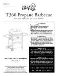
T405 Propane Barbecue
S A F E U S E , C A R E A N D A S S E M B LY M A N U A L
DANGER
If you smell Gas
1. Shut off gas to the appliance.
2. Extinguish any open flame.
3. Open lid.
4. If odor continues, keep away from the
appliance and immediately call your
gas supplier or your fire department.
WA R N I N G
1. Do not store or use gasoline or other
flammable vapours and liquids in the
vicinity of this or any other appliance.
2. An LP cylinder not connected for use
shall not be stored in the vicinity of this
or any other appliance.
WA R N I N G
Failure to follow all of the Manufacturer’s
instructions could result in hazardous
fires, explosions, property damage, or
serious personal injury or even death.
ONE
YEAR
LIMITED
WA R R A N T Y
85-1618 - 4
G43406
WA R N I N G
Follow all leak check procedures carefully
prior to operation of barbecue, even if
grill was dealer assembled. Do not try to
light this barbecue without reading the
Lighting Instructions section of this manual.
Read and save this manual for future reference.
If pre-assembled, leave this manual
with unit for consumer’s future reference.
For product inquires, parts, and warranty and
troubleshooting support, please call 1-877-707-5463.
THIS BARBECUE IS FOR
O U T D O O R U S E O N LY
WA R R A N T Y
Important: Should you have difficulty operating this product, or have a part that has
become defective within the stated warranty period, do not return to store.
Stores do not stock replacment parts and are unable to help with troubleshooting
advice. Please call 1-877- 707-5463. Have your Proof of purchase, serial number and
model number available so that the customer support agent can be of assistance.
WA R R A N T Y
1 Year Limited Warranty
This Masterchef Barbecue carries a One year limited warranty against defects in manufacturing workmanship. This Limited Warranty is nontransferable and becomes void if
used for commercial or rental purposes. This warranty applies only when grill is used in
Canada. The bill of sale or a copy will be required together with the serial number and
model number when making any warranty claims from Trileaf Distribution.
Trileaf Distribution reserves the right to have its representatives inspect any product or part prior to honoring any warranty claim. Trileaf Distribution shall not be
liable for any transportation charges, or labor cost. This warranty is for replacement
of defective parts only. The Manufacturer will not be responsible for incidental or
consequential damages or any labor cost. Inability to provide proof of purchase, or if
warranty coverage has expired, any request for parts will be subject to parts, shipping
and handling fees.
This limited warranty does not cover damage due to chipping and scratching of
porcelain or painted surfaces including Cooking grates, nor does it cover corrosion or
discoloration due to misuse, lack of maintenance, grease fires, hostile environments,
accidents, alterations, abuse or neglect, improper installation and failure to read and/
or abide by any product warnings. This limited warranty does not cover any damage
sustained during removal or storage of this BBQ. Part failure due to lack of cleaning
and maintenance, including grease fires and flash fires will not be covered under this
manufacturers warranty. This limited warranty does not cover any scratches or dents,
corrosion or discoloring caused by heat, abrasive or chemical cleaners. Parts installed
from other manufactures will nullify this warranty.
1 Year Limited Warranty
Should deterioration of parts occur to the degree of non-performance within the
duration of the warranty coverage a replacement part will be provided. The following
functional parts are included under this warranty: burner, flame tamer, cooking grate,
igniter, valve assembly, and regulator.
Purchaser: By accepting delivery of this Barbecue the purchaser, hereby accepts
the foregoing and expressly waives any other remedy and damages, direct, indirect, and consequential.
INFORMATION
INSTALLATION
The installation of this appliance must be in accordance with all local codes, or in
the absence of local codes:
UÊ
>>`>ÊÃÌ>>ÌÊÕÃÌÊVvÀÊÌÊÌ
iÊVÕÀÀiÌÊ>Ì>ÊÃÌ>`>À`Ã]ÊÜ
V
Ê>ÌÊ
this time are CAN/CGA-B149.1/2-Natural Gas/Propane installation code.
a) Do not store a spare LP-gas cylinder under or near this appliance;
b)Never fill the cylinder beyond 80 percent full; and
c) If the information in “(a)” and “(b)” is not followed exactly, a fire causing
death or serious injury may occur.
ADDITIONAL
WA R N I N G S
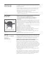
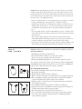
Minimum clearance to adjacent combustible materials:
UÊÇÈÊVÊÎä®ÊvÀÊvÕÀÌ
iÃÌÊ«ÀÌÀÕ`}Êi`}iÊÊÃ`iÊvÊL>ÀLiVÕi°
UÊÇÈÊVÊÎä®ÊvÀÊvÕÀÌ
iÃÌÊ«ÀÌÀÕ`}Êi`}iÊÊL>VÊvÊL>ÀLiVÕi°
See Drawing A
Minimum clearance of 76 cm (30’)
on both sides and back of the barbecue.
Drawing A
USE
OF
L . P.
GAS
CYLINDER
Self-contained
Propane Gas System
UÊÜ>ÞÃÊii«ÊÌ
iÊ>Ài>Ê>ÀÕ`ÊÌ
ÃÊL>ÀLiVÕiÊVi>Ê>`ÊVi>ÀÊvÊ>ÞÊ>`Ê>ÊVLÕÃtible materials such as gasoline or other inflammable liquids, paper or oily rags.
UÊDo not operate this barbecue under any overhanging or unprotected construction.
UÊ,iiLiÀÊÌ
ÃÊL>ÀLiVÕiÊÃÊvÀÊoutdoor use only and is not for use on any boat
or recreational vehicle.
UÊ1ÃiÊÌ
ÃÊL>ÀLiVÕiÊÕÌ`ÀÃÊÊ>ÊÜiÛiÌ>Ìi`Ê>Ài>Ê>`ÊÜiÊÀiVi`Ê>ÌÊi>ÃÌÊ
3m (10’) from any dwelling or other buildings.
UÊDo not use in garages, or any other enclosed area.
UÊDo not leave your barbecue unattended while in operation.
UÊDo not obstruct the flow of combustion and ventilation air to the barbecue.
UÊDo not use while under the influence of drugs or alcohol.
UÊDo not store any spare L.P. (propane) cylinder, full or empty, under or near
your barbecue.
UÊDo not allow children to play anywhere near the barbecue.
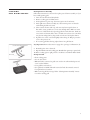
The self-contained (propane) gas system is designed to be used with only a 9.1 kg
(20 lb) propane cylinder equipped with a type-1 cylinder valve and incorporating
an overfill protection device (O.P.D.). This barbecue cannot be connected to an
existing #510 P.O.L. type valve cylinder (which has left-handed threads).
DO NOT connect to a propane cylinder exceeding 9.1 kg capacity or use a
cylinder with any other type of cylinder valve connection device.
The type-1 valve can easily be recognized by the large external thread on the
outside of the valve.Older existing valves do not have this outer external thread.
Any attempt to connect a regulator to any connector other than the mating type-1
connector could result in fires, injuries or property damage, and could take out the
important safety features built into the type-1 system. Also connecting the #510
P.O.L. fitting to the cylinder will negate the flow control and the temperature
shut-off features built into the new type-1 connection system.
UÊ/
iÊVÞ`iÀÊÃ
Õ`ÊÌÊiÝVii`Ê{ÇÓÊÊ£nÊ£ÉÓ®ÊÊ
i}
ÌÊ>`ÊΣÇÊÊ£ÓÊ
£ÉÓ®ÊÊ`>iÌiÀ°
LP-gas supply cylinder to be used must be constructed and marked in accordance
ÜÌ
ÊÌ
iÊëiVwV>ÌÃÊvÀÊ*}>ÃÊVÞ`iÀÃÊvÊÌ
iÊ1°-°i«>ÀÌiÌÊv/À>ëÀÌ>tion (DOT) or the National Standard of Canada, CAN/CSA-B339, Cylinders
Spheres and Tubes for the Transportation of Dangerous Goods.
1
DANGER
UÊ 6,ÊÃÌÀiÊ>Êë>ÀiÊ*ÊÌ>ÊÕ`iÀÊÀÊ
near grill or in enclosed areas.
UÊ iÛiÀÊwÊÌ
iÊVÞ`iÀÊLiÞ`Ênä¯ÊvÕ°
UÊÊÛiÀwi`ÊÀÊ«À«iÀÞÊÃÌÀi`Ê
Ì>ÊÃÊ>Ê
>â>À`Ê`ÕiÊÌÊ«ÃÃLiÊ}>ÃÊ
Àii>ÃiÊvÀÊÌ
iÊÃ>viÌÞÊÀiivÊÛ>Ûi°
UÊvÊÞÕÊÃii]ÊÃiÊÀÊ
i>ÀÊiÃV>«}Ê}>Ã]Ê
i`>ÌiÞÊ}iÌÊ>Ü>ÞÊvÀÊÌ
iÊ*ÊÌ>É
}ÀÊ>`ÊV>ÊÞÕÀÊwÀiÊ`i«>ÀÌiÌ°
UÊvÊÌ
iÊ>LÛiÊÃÊÌÊvÜi`ÊiÝ>VÌÞ]Ê>Ê
wÀiÊV>ÕÃ}Ê`i>Ì
ÊÀÊÃiÀÕÃÊÕÀÞÊ
>ÞÊVVÕÀ°
The Cylinder must also be equipped with:
UÊÊÃ
ÕÌvvÊÛ>ÛiÊÜÌ
Ê>ÊVÀÀiVÌÊVÞ`iÀÊÛ>ÛiÊÕÌiÌÊ>ÃÊëiVwi`ÊÊVÕÀÀiÌÊÃÌ>`>À`ð
UÊ
>>`>\Ê
ÉÊ
Ê£°È}ÇÊ"ÕÌ`ÀÊ>ÃÊÀð
UÊ1°-°\Ê -Ê<Ó£°xn>ÓääÈÉ
-Ê£°È>ÓääÈÊ"ÕÌ`ÀÊ
}Ê««>Við
a) Constructed and marked in accordance with the Specifications for LP-Gas
Þ`iÀÃÊvÊÌ
iÊ1°-°Êi«>ÀÌiÌÊvÊ/À>ëÀÌ>ÌÊ°"°/°®ÊÀÊÌ
iÊ >Ì>Ê
Standard of Canada, CAN/CSA-B339, Cylinders, Spheres and Tubes for Transportation of Dangerous Goods; and Commission, as applicable; and
b)Cylinder connection device compatible with the connection for outdoor
cooking appliances.
c) A listed Overfilling Protection Device (O.P.D.).
d) A safety relief valve with direct connection to the vapour space of the cylinder.
e) A collar to protect the tank shut-off valve.
f ) A device for vapour withdrawal.
g) A ring on the bottom to secure the tank to its support assembly.
Warning
UÊÜ>ÞÃÊÌÕÀÊvvÊÌ
iÊVÞ`iÀÊÛ>ÛiÊV«iÌiÞÊÜ
iÊÌ
iÊL>ÀLiVÕiÊÃÊÌÊÊÕÃi°
UÊÜ>ÞÃÊ
>`iÊÌ
iÊÌ>ÊÛ>ÛiÊÜÌ
ÊÕÌÃÌÊV>Ài°
UÊ iÛiÀÊViVÌÊ>ÊÕÀi}Õ>Ìi`Ê°*°Ê}>ÃÊVÞ`iÀÊÌÊÌ
iÊL>ÀLiVÕi°
UÊÜ>ÞÃÊii«ÊÌ
iÊVÞ`iÀ]ÊÊÕÃi]ÊÃiVÕÀiÞÊv>ÃÌii`ÊÊ>ÊÕ«À}
ÌÊ«ÃÌ°
UÊ iÛiÀÊÃÌÀiÊ>Êë>ÀiÊVÞ`iÀ]Êi«ÌÞÊÀÊvÕ]Êi>ÀÊÀÊÕ`iÀÊÌ
iÊL>ÀLiVÕiÊ
when in operation.
UÊ iÛiÀÊiÝ«ÃiÊÌ
iÊVÞ`iÀÃÊÌÊ`ÀiVÌÊÃÕ}
ÌÊÀÊiÝViÃÃÛiÊ
i>Ì°
UÊ iÛiÀÊÃiÀÌÊ>ÞÊ`ÊvÊLiVÌÃÊÌÊÌ
iÊÛ>ÛiÊÕÌiÌÊ>ÃÊÌ
ÃÊ>ÞÊ`>>}iÊÌ
iÊ
backcheck; a backcheck that is damaged can leak, and a leaking propane cylinder
can result in fires or explosions, property damage, severe injuries or death.
To Connect Regulator
Carefully insert brass nipple of regulator connection into tank outlet. Screw black
plastic nut clockwise onto tank valve outlet until it comes to a stop. Hand-tighten
only. Do not use tools of any kind.
TRANSPORTATION
AND
OF
STORAGE
L . P.
CYLINDER
The propane cylinder is totally safe when handled properly, but if misused, the
result could be an explosion or fire resulting in serious personal injury and/or
property damage.
Warnings
UÊÜ>ÞÃÊÀiV>«ÊÌ
iÊVÞ`iÀÊÜÌ
ÊV>«Ê«ÀÛ`i`ÊÜ
iÊÌÊViVÌi`ÊÌÊÌ
iÊL>ÀLiVÕi°
UÊDo not store the cylinder in any enclosed area such as a garage, and make sure
the storage area has lots of ventilation.
UÊDo not store the cylinder near any appliances, or in any areas that may become
hot such as the trunk of a vehicle.
UÊ>iÊÃÕÀiÊÌ
iÊVÞ`iÀÊÃÊÕÌÊvÊÌ
iÊÀi>V
ÊvÊV
`Ài°
UÊ7
iÊÌÀ>ëÀÌ}ÊÀÊÃÌÀ}ÊÌ
iÊVÞ`iÀ]Ê>iÊÃÕÀiÊÌÊÃÊÊ>ÊÕ«À}
ÌÊ«ÃÌÊ
and not on its side.
UÊDo not smoke around the cylinder, especially when transporting it in a vehicle.
2
FILLING
L . P.
THE
CYLINDER
For safety reasons the LP gas cylinder, if supplied with your barbecue, has been
shipped empty. The cylinder must be filled prior to use and must have the air
purged. For safety, follow these instructions when having your cylinder filled:
UÊ>ÛiÊÞÊÞÕÀÊV>ʵÕ>wi`Ê*Ê}>ÃÊ`i>iÀÊwÊÀÊÀi«>ÀÊ>ÊVÞ`iÀ°
UÊDo not overfill the cylinder beyond the safe 80% fill level.
UÊ>iÊÃÕÀiÊÌ
iÊ`i>iÀÊÌiÃÌÃÊ>`ÊV
iVÃÊÌ
iÊVÞ`iÀÊvÀÊi>ÃÊ>vÌiÀÊw}°
WA R N I N G
If the above instructions are not completely adhered to, it could cause a
fire/explosion, resulting in death or serious Injury, or property damage.
SAFETY
AND
HOSE
REGULATOR
Propane Models: Your barbecue is designed to operate on L.P. propane gas at a
«ÀiÃÃÕÀiÊvÊÓ°Ç{Ê«>Ê££ÊÜ>ÌiÀÊVÕ®°ÊÊÀi}Õ>ÌÀÊ«ÀiÃiÌÊÌÊÌ
ÃÊ«ÀiÃÃÕÀiÊÃÊÃÕ«plied with the barbecue and must be used.
This regulator is equipped with the type-1 quick-closing connecting system, which
incorporates these safety features:
UÊ7ÊÌÊ>ÜÊ}>ÃÊÌÊyÜÊÕÌÊ>Ê«ÃÌÛiÊÃi>Ê
>ÃÊLiiÊ>`i°
UÊ>ÃÊ>ÊÌ
iÀ>ÊV«iÌÊÌ
>ÌÊÜÊ>ÕÌ>ÌV>ÞÊÃ
ÕÌÊvvÊÌ
iÊyÜÊvÊ}>ÃÊLitween 115–150ºC (240–300ºF).
UÊ>ÃÊ>ÊyÜÊÌ}Êvi>ÌÕÀi]ÊÜ
V
ÊÜÊÀiÃÌÀVÌÊÌ
iÊyÜÊvÊ}>ÃÊÌÊ£äÊVÕLVÊviiÌÉ
ÕÀ°
Warning
Should the large, black thermal-sensitive coupling nut be exposed to any extreme
temperatures above 115ºC it will soften and allow the regulator probe to disengage
from the valve, and will shut off the gas. Should this occur, do not try to reconnect the nut; instead replace the whole regulator assembly with a new one (see the
attached parts listing for details). The regulator probe also contains a flowsensitive
feature, which limits the flow of gas to 10 cubic feet/hour, in the event of a regulator malfunction or hose leak. If the flow control feature is activated, the cause
of this excessive gas flow should be investigated and corrected before using the
barbecue again.
3
Attention: Improperly lighting the barbecue can activate the flow control feature,
resulting in lower heat output. If this occurs, the re-flow feature must be reset by
turning off all the burner controls and the cylinder valve. Wait at least 30 seconds
before slowly turning on the cylinder valve, and then after another 5 seconds turn
the burner valve on and light the barbecue.
UÊ iÛiÀÊViVÌÊÌ
ÃÊL>ÀLiVÕiÊÌÊ>ÊÕÀi}Õ>Ìi`Ê«À«>iÊ}>ÃÊÃÕ««Þ]ÊÀÊÌÊ>Ì
iÀÊ
kind of gas. Do not alter or change the hose or regulator in any way.
UÊ6ÃÕ>ÞÊëiVÌÊÌ
iÊÜ
iÊ
ÃiÊ>ÃÃiLÞÊLivÀiÊi>V
ÊÕÃiÊvÀÊiÛ`iViÊvÊÜi>ÀÊÀÊ
damage such as cracks, burns, or even cuts. If any damage is found, replace the
>ÃÃiLÞÊLivÀiÊÕÃ}ÊÌ
iÊL>ÀLiVÕi°Ê1ÃiÊÞÊÌ
iÊÀiVi`i`ÊÀi«>ViiÌÊ
hose.
UÊ/Ê>Û`Ê«ÃÃLiÊ`>>}iÊÌÊÌ
iÊ
Ãi]Êdo not allow any grease or other hot materials to fall on the hose, and make sure the hose does not contact any hot surfaces
of the barbecue.
UÊ/
iÊViVÌÊwÌÌ}ÊÕÃÌÊLiÊ«ÀÌiVÌi`ÊÜ
iÊ̽ÃÊ`ÃViVÌi`ÊvÀÊÌ
iÊ
cylinder. Do not allow the fitting to bump or drag on the ground as nicks and
scratches could help create a leak when connecting back to the cylinder.
UÊÌÊÃÊ«ÀÌ>ÌÊÌÊ`ÊÌ
iʺi>Ê/iÃ̻ʫÀVi`ÕÀiÊiÛiÀÞÊÌiÊ>ÊVÞ`iÀÊÃÊÀiwi`]ÊÀÊ>ÞÊ
of the components are changed, and especially at the beginning of a new season.
SAFETY
Attention: A leak test ensures that there are no gas leaks prior to lighting your barbeque.
LEAK
Perform A “Leak Test”
TESTING
UÊivÀiÊ}
Ì}ÊÞÕÀÊL>ÀLiVÕiÊvÀÊÌ
iÊwÀÃÌÊÌi°
UÊÛiÀÞÊÌiÊÌ
iÊVÞ`iÀÊÃÊÀiwi`]ÊÀÊ>ÞÊV«iÌÊÃÊÀi«>Vi`°
UÊÌÊi>ÃÌÊViÊiÛiÀÞÊÞi>À]Ê«ÀiviÀ>LÞÊ>ÌÊÌ
iÊÃÌ>ÀÌÊvÊÌ
iÊÃi>ð
UÊ7
iÊ
>Û}Ê`vwVÕÌÞÊ}
Ì}ÊLÕÀiÀÃ]ÊÀÊiÝ«iÀiV}ÊÀÀi}Õ>ÀÊLÕÀÊ«>ÌÌiÀð
The “Leak Test” must be done outdoors, away from heat, open flames and flammable
liquids. Do notÊÃiÊÜ
iÊ«iÀvÀ}ÊÌ
iÊÌiÃÌ°Ê1ÃiÊÞÊ>ÊÝÌÕÀiÊvÊxäÉxäʵÕ`Ê
soap and water for leak testing. Never use a match or open flame.
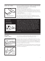
The Following Must Be Checked
Drawing B
Drawing C
Drawing D
À>Ü}Ê
vÊiµÕ««i`ÊÜÌ
Ê>ÊÃ`iÊLÕÀiÀ®
4
UÊ/
iÊÌ>ÊÛ>ÛiÊVÕ`}ÊÌ
iÊÌ
Ài>`ÃÊÌÊÌ
iÊÌ>Ê`À>Ü}Ê
®°
UÊÊÌ>ÊÜi`ÃÊ`À>Ü}Ê®°
UÊ,i}Õ>ÌÀÊwÌÌ}ÃÊ>`ÊÌ>ÊViVÌÃÊ`À>Ü}Ê
®°
UÊÊ
ÃiÊViVÌÃÊ`À>Ü}Ê®]Ê«ÕÃÊÃ`iÊLÕÀiÀÊ
ÃiÃÊvÊÃÊiµÕ««i`Ê`À>Ü}Ê®°
UÊ7Ì
Ê>ÊiÜÞÊwi`Ê>`ÊÌiÃÌi`Ê«À«>iÊÌ>Ê>ÌÌ>V
i`ÊÌÊÌ
iÊL>ÀLiVÕiÊ>`Ê>ÊÌ
iÊ
controls turned OFF, slowly open the cylinder valve one full turn.
UÊÀÕÃ
Ê->«ÊÃÕÌÊÊ>ÊViVÌÃÊ>`ÊV«iÌÃÊÃÌi`Ê>LÛiÊ>`ÊÃ
ÜÊÊ
Ì
iÊ`À>Ü}ÃÊ]Ê
]ÊÊ>`Ê°
UÊÊV>ÀivÕÞÊvÀÊLÕLLiÃÊvÀ}]ÊÜ
V
ÊÃÊ>Ê`V>ÌÊvÊi>}Ê}>ð
UÊ/}
ÌiÊÌ
iÊViVÌÃÊ>ÌÊÌ
iÊLÕLLi`Ê>Ài>ÃÊÕÌÊÀiÌiÃÌ}ÊÃ
ÜÃÊÊ`V>ÌÊvÊ
any leaks (shut off cylinder while correcting any leaks).
UÊ-
ÕÌÊvvÊÌ
iÊVÞ`iÀÊÛ>ÛiÊ>`ÊiÃÕÀiÊ>ÊVÌÀÊÛ>ÛiÃÊ>ÀiÊvv°
UÊÊÌÊÕÃiÊÌ
iÊL>ÀLiVÕiÊvÊ>ÞÊi>ÃÊV>ÌÊLiÊÃÌ««i`°Ê/ÕÀÊvvÊÌ
iÊ}>ÃÊVÞ`iÀÊ
valve, remove the gas cylinder and seek assistance from a qualified gas appliance
service mechanic or gas dealer.
PRIOR
TO
USING
ÃiÀÌÊÛ>ÛiÊÕÌiÌÃÊÌÊ6iÌÕÀÊÌÕLiÃ
>««ÀÝ>ÌiÞÊÈÊ£É{»®
Drawing F
ÊÌÊÕÃiÊÞÕÀÊL>ÀLiVÕiÊÕÌÊÞÕÊ
>ÛiÊV>ÀivÕÞÊÀi>`Ê>`ÊvÕÞÊÕ`iÀÃÌ>`Ê
>ÊÌ
iÊvÀ>ÌÊÊÌ
ÃÊ>Õ>°Ê*i>ÃiÊiÃÕÀiÊÌ
iÊvÜ}\
UÊ9ÕÀÊL>ÀLiVÕiÊÃÊ«À«iÀÞÊ>ÃÃiLi`°
UÊ/
iÀiÊ>ÀiÊÊi>ÃÊÊÌ
iÊÃÞÃÌiÊÃiiʺi>Ê/iÃÌ»®°
UÊ/
iÊLÕÀiÀÊÃÊ«À«iÀÞÊ>ÃÃiLi`]ÊÜÌ
ÊÌ
iÊÛiÌÕÀÊÌÕLiÃÊÃi>Ìi`ÊÛiÀÊÌ
iÊÛ>ÛiÊÕÌlets (drawing F) and that there is nothing blocking the venturi tubes (drawing G).
UÊÃÕÀiÊÌ
>ÌÊ>Ê«ÜiÀÊVÀ`ÃÊ>`ÉÊÀÊ}>ÃÊÃÕ««ÞÊ
ÃiÃÊÜÊÌÊÌÕV
ÊÀÊLiÊi>ÀÊÌ
iÊ
surfaces that will get hot.
UÊ/
iÊL>ÀLiVÕiÊÃÊÊ>ÊÃ>viÊV>ÌÊÃiiÊÃÌ>>Ì®°
ÃÕÀiÊÌ
>ÌÊÌ
iÊÛ>ÛiÊÕÌiÌÃÊ}ÌiÀÊiiVÌÀ`i®Ê>ÀiÊ>ÃÃiLi`ÊÌÊÌ
iÊÛiÌÕÀÊ
ÌÕLiÃÊ>««ÀÝ>ÌiÞÊÈÊÊ£É{®Ê>`ÊÌ
>ÌÊÌ
iÊÛ>ÛiÊÕÌiÌÃÊ>`ÊÛiÌÕÀÊÌÕLiÃÊ>ÀiÊ
approximately parallel to the bottom of the lower body.
During shipment or storage, it’s possible that small insects like spiders could
find their way into the venturi tubes and nest or make webs. This could block
the flow of gas through the venturi tube causing a smoky yellowish flame, or
prevent a burner from lighting. It could even cause the gas to burn outside the
Venturi tube, which could seriously damage your grill. If these occurs, turn
off the gas flow and wait for the barbecue to cool down. When the barbecue
has cooled, remove the burner and clean out the venturi tubes with a brush or
pipe cleaner. Replace the burner and ensure that the venturi tubes are seated
over the Igniter Electrode located on the gas valves. Cleaning the venturi tubes
should be conducted periodically, especially at the start of the season.
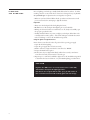
WA R N I N G
Natural Hazards
Insects ans Spiders
Note: Damage resulting from blocked venturi tubes is not covered under
the warranty.
Drawing G
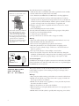
CAUTION
SPIDER
Control
*>i
If you notice that your grill is getting hard to light or that the flame is not as
strong as it should be, take the time to check and clean the venturis.
ALERT
Gas Collector
ÝÊEÊ}ÌÀ
Burner
-«`iÀÊ7iLÃ
Ã`iÊ6iÌÕÀ
6>Ûi
Air Shutter
In some areas of the country, spiders or small insects have been known to create
“flashback” problems. The spiders spin webs, build nests and lay eggs in the grill is
6iÌÕÀÊÌÕLiîÊLÃÌÀÕVÌ}ÊÌ
iÊyÜÊvÊ}>ÃÊÌÊÌ
iÊLÕÀiÀ°Ê/
iÊL>Vi`Õ«Ê}>ÃÊV>Ê
}ÌiÊÊÌ
iÊ6iÌÕÀÊLi
`ÊÌ
iÊVÌÀÊ«>i°Ê/
ÃÊÃÊÜÊ>ÃÊ>Êy>Ã
L>VÊ>`ÊÌÊ
can damage your grill and even cause injury.
/Ê«ÀiÛiÌÊy>Ã
L>VÃÊ>`ÊiÃÕÀiÊ}`Ê«iÀvÀ>ViÊÌ
iÊLÕÀiÀÊ>`Ê6iÌÕÀÊ>ÃÃibly should be removed from the grill and cleaned before use whenever the grill has
been idle for an extended period.
6iÌÕÀ
vÌÊ"ÕÌ
ÕÀiÀÊÃÃiLÞ
,iÛi
ÕÀiÀÊ
«Ã
-«`iÀÊ7iLÃ
i>Ê"ÕÌÊ6iÌÕÀ Ã`iÊ6iÌÕÀ
5
LIGHTING
THE
BARBECUE
Prior to lighting your barbeque, visually check all hoses before each use, for nicks,
cracking, abrasions or cuts. If the hose is found to be damaged in any way, do not
use your barbeque. A replacement hose and regulator is required.
UÊ>iÊÃÕÀiÊÞÕÊ
>ÛiÊvÜi`Ê>ÊÌ
iÊV
iVÃ]Ê«ÀVi`ÕÀiÃÊ>`ÊÃÌÀÕVÌÃÊÊ>Ê
previous sections before attempting to light the barbecue.
Important
UÊÜ>ÞÃÊÀ>ÃiÊÌ
iÊL>ÀLiµÕiÊ`ÊLivÀiÊ}
Ì}ÊÌ
iÊLÕÀiÀ°
UÊDo not lean over the barbeque when lighting in case of back flash.
UÊ>}ÊÃÕÀiÊÌ
iÊ>ÊL>ÀLiVÕiÊVÌÀÊLÃÊ>ÀiÊvv]ÊÃÜÞÊ>`ÊV>ÀivÕÞÊ«iÊ
the propane gas cylinder valve.
UÊ6ÃÕ>ÞÊV
iVÊÌ
iÊy>iÃÊiÛiÀÞÊÌiÊÞÕÊ}
ÌÊÞÕÀÊL>ÀLiµÕi°ÊvÊÌ
iÊy>iÊÃÊ>Lnormally small or smokey yellow – shut off the barbeque and check the venturi
tubes for blockage or refer to the Troubleshooting Guide.
Using The Igniter To Light The Burner
ÃÕÀiÊLÕÀiÀÊVÌÀÊLÃÊÊÌ
iÊvvÊ«ÃÌÊLivÀiÊ«i}Ê}>ÃÊÃÕ««Þ°
1. Open the lid before lighting.
2. Open the gas supply valve and wait 5 seconds.
3. Push in and turn a single main burner control knob to ‘HIGH’.
4. Depress the Push button igniter.
5. If the burner does not light immediately (within four seconds), turn burner
control knob off and wait 5 minutes to clear the gas.
È°Ê,i«i>ÌÊÃÌi«ÃÊ£ÊÌÊx°ÊvÊLÕÀiÀÊÃÌÊv>ÃÊÌÊ}
Ì]ÊÀiviÀÊÌÊÌ
iÊ/ÀÕLiÃ
Ì}ÊÕ`iÊ
to determine the cause and solution, or try the Match Lighting procedure below.
CAUTION
If ignition does NOT occur in 5 seconds, turn the burner controls OFF,
wait 5 minutes and repeat the lighting procedure.
If the burner does not ignite with the valve open, gas will continue to
flow out of the burner and could accidently ignite with risk of injury.
6
Match-Lighting
Do not lean over grill while lighting.
1. Open lid. Turn on gas at LP cylinder.
2. Push in and turn left burner knob to HI. Be sure burner lights and stays lit.
3. Place lit match into match holder, then into lighting hole on left side of grill.
Match Lighting Procedure
}
Ì}ÊÌ
iÊÌ
iÀÊÃ`iÊvÊÌ
iÊ`Õ>ÊLÕÀiÀ\ÊOnce one side of the dual burner has
been lit, push in and turn the other control knob to ‘HIGH’. The unlit burner will
light automatically.
WA R N I N G
If the heat output is too low, the flow control feature may have been activated by a gas leak or improper lighting procedure.
If so, turn off the burner valve and cylinder valve, and perform the “Leak
Test”. If there aren’t any leaks, re-light the burner.
WA R N I N G
Use this slot for manual match-lighting
Never stand with your head directly over the Barbecue when preparing to
light the main burners, to prevent possible bodily injury.
WA R N I N G
IF THE SELECTED BURNER DOES NOT LIGHT,
immediately turn the burner control knob and cylinder valve to the OFF
position, to prevent gas buildup. Wait five minutes for the gas to clear and
then repeat the preceding starting procedure. If the burner will not light
when using the ignitor, follow the match lighting instructions.
Shutting Down The Barbecue After Use
UÊ/ÕÀÊvvÊÌ
iÊ}>ÃÊVÞ`iÀÊÛ>Ûi°
UÊ/ÕÀÊÌ
iÊLÕÀiÀÊVÌÀÊÛ>ÛiÊÌÊÌ
iʺ"vvʻʫÃÌ°
This sequence is important as it prevents residual gas from being left in the system
under pressure and will make the next use easier.
7
TIPS
YOUR
ON
USING
BARBECUE
First time use: Before cooking, turn on the barbecue and operate on “High” for
about 10–15 minutes with the lid open. Close the lid and continue to run the barbecueon “High” for another few minutes. Perform shut down procedure and allow
your BBQ to cool down before re-lighting.
Preparation: The barbecue should be preheated to get the heat plate hot before adding any food. This is done by lighting the barbecue and running at “High” for up to
ten minutes with the lid down. If the food you are cooking needs a lower temperature, turn the control knob to the required setting before adding food.
Cooking Time: Get to know your grill. Cooking time will depend on foods being
cooked, the thickness of food and the weather. You will learn that on a hot day, a
lower setting will work better and on a cold day a higher setting may work better. Do
not attempt to reduce cooking time by cooking at higher temperatures.
Flare-ups: Always monitor the BBQ carefully while cooking and turn the flame level
`ÜÊÀÊ"ÊvÊy>Ài1«ÃÊÌiÃvÞ°Ê>ÀiÕ«ÃÊV>ÊVÀi>ÃiÊÌ
iÊÌi«iÀ>ÌÕÀiÊÊÌ
iÊ
barbecue and add to the buildup of grease, increasing the risk of a grease fire. Some
flare-ups are normal to create smoke, which helps add to the flavour of your food. To
keep these flare-ups to the desire level, do the following:
UÊÜ>ÞÃÊÌÀÊv>ÌÊvÀÊÃÌi>ÃÉÀi`Êi>ÌÃÊLivÀiÊ}À}°
UÊ
ÊV
ViÊ>`Ê«ÀÊÊ>ÊÜiÀÊÃiÌÌ}°
UÊ>iÊÃÕÀiÊÌ
iÊ
i>ÌÊ«>ÌiÊÃÊÀi>Ã>LÞÊVi>°
UÊ>iÊÃÕÀiÊÌ
iÊ}Ài>ÃiÊ`À>Ê
iÊÃÊVi>ÀÊ>`ÊÌ
>ÌÊÌ
iÊ}Ài>ÃiÊV>ÌV
iÀÊÃÊÌÊwi`°
UÊÜ>ÞÃÊVÊÜÌ
ÊÌ
iÊ`Ê`Ü]Ê>`ÊVÊ>ÌÊÌ
iÊÜiÃÌÊivwViÌÊ
i>ÌÊÃiÌÌ}°
Note: With the lid down, you will keep a more consistent temperature inside the
cooking area and use less energy/gas.
WA R N I N G
Do Not leave your barbecue unattended, and watch out for children around the barbecue. Make sure the barbecue is functioning
safely at all times. DO NOT move the barbecue while cooking.
n
CLEANING
Cleaning the Burner Assembly
AND
Follow these instructions to clean and/or replace parts of burner assembly or if you
have trouble igniting grill.
1. Turn off control knobs and LP cylinder.
Ó°ÊÊ ,iÛiÊV}Ê}À>ÌiÊ>`Êy>iÊÌ>iÀ
ΰÊÊ 1`iÀÊ}ÀÊÀiÛiÊ}Ài>ÃiÊVÕ«]Ê`ÃViVÌÊ}ÌÀÊÜÀiÊvÀÊLÕÀiÀ°
4. Inside grill remove burner assembly (A), clean ceramic portion of electrode
with rubbing alcohol and a swab.
5. Clean outside of burner with soap and water. Lay burner upside down on
flat surface, insert garden hose to force water through tubes. Make sure water
comes out of all burner holes. Open clogged holes with a thin wire. Shake out
excess water and examine holes. Due to normal wear and corrosion some holes
may become enlarged. If any large cracks or holes are found replace burner.
È°ÊÊ vÊ}ÀÊÃÊÌÊLiÊÃÌÀi`]ÊV>ÌÊLÕÀiÀÊ}
ÌÞÊÜÌ
ÊV}Ê°Ê7À>«ÊÊ«ÀÌiVÌÛiÊ
cover to keep insects out.
Ç°ÊÊ vÊÌÊÃÌÀ}Ê}ÀÊ>vÌiÀÊVi>}]ÊÀi«>ViÊLÕÀiÀÊÌÊ}ÀÊLÌÌ°
MAINTENANCE
ÀÀiVÌÊLÕÀiÀÌÛ>ÛiÊi}>}iiÌ
Very Important: Burner tubes must re-engage valve openings. See illustration (A).
n°ÊÊ ,i>ÌÌ>V
Ê}ÌÀÊÜÀiÊÌÊiiVÌÀ`i°
°ÊÊ ,i«ÃÌÊy>iÊÌ>iÀÊ>`ÊV}Ê}À>Ìi°Ê,i>ÌÌ>V
ÊVi>Ê}Ài>ÃiÊVÕ«ÊÌÊ}Ài>ÃiÊ
°
10. Before cooking again on grill, perform a “Leak Test” and “Burner Flame Check”.
Storing Your Grill
Burner Tube
6>Ûi
UÊ
i>ÊV}Ê}À>Ìið
UÊ-ÌÀiÊÊ`ÀÞÊV>Ì°
UÊ7
iÊ*ÊÌ>ÊÃÊViVÌi`ÊÌÊ}À]ÊÃÌÀiÊÕÌ`ÀÃÊÊÜiÊÛiÌ>Ìi`Êë>ViÊ>`Ê
out of reach of children.
UÊ
ÛiÀÊ}ÀÊvÊÃÌÀi`ÊÕÌ`Àð
UÊ-ÌÀiÊ}ÀÊ`ÀÃÊ" 9ÊvÊ*ÊÌ>ÊÃÊÌÕÀi`ÊvvÊ>`Ê`ÃViVÌi`]ÊÀiÛi`Ê
from grill and stored outdoors.
UÊ7
iÊÀiÛ}Ê}ÀÊvÀÊÃÌÀ>}iÊvÜʺ
i>}ÊÕÀiÀÊÃÃiLÞ»ÊÃÌÀÕVtions before starting grill.
9
Food Safety
Food safety is a very important part of enjoying the outdoor cooking experience.
To keep food safe from harmful bacteria, follow these four basic steps:
Clean: Wash hands, utensils, and surfaces with hot soapy water before and after
handling raw meat and poultry.
Separate: Separate raw meats and poultry from ready-to-eat foods to avoid cross
VÌ>>Ì°Ê1ÃiÊ>ÊVi>Ê«>ÌÌiÀÊ>`ÊÕÌiÃÃÊÜ
iÊÀiÛ}ÊVi`Êv`ð
Cook:Ê
Êi>ÌÊ>`Ê«ÕÌÀÞÊÌ
ÀÕ}
ÞÊÌÊÊL>VÌiÀ>°Ê1ÃiÊ>ÊÌ
iÀiÌiÀÊÌÊ
ensure proper internal food temperatures.
Chill:Ê,ivÀ}iÀ>ÌiÊ«Ài«>Ài`Êv`ÃÊ>`ÊivÌÛiÀÃÊ«À«ÌÞ°
How To Tell If Meat Is Grilled Thoroughly
UÊi>ÌÊ>`Ê«ÕÌÀÞÊVi`ÊÊ>Ê}ÀÊvÌiÊLÀÜÃÊÛiÀÞÊv>ÃÌÊÊÌ
iÊÕÌÃ`i°Ê1ÃiÊ>Ê
meat thermometer to be sure food has reached a safe internal temperature, and cut
into food to check for visual signs of doneness.
UÊ7
iÊ«ÕÌÀÞÊÃ
Õ`ÊÀi>V
Ê£näcÊÆÊLÀi>ÃÌÃ]Ê£ÇäcÊ°ÊÕViÃÊÃ
Õ`ÊÀÕÊVi>ÀÊ>`Ê
flesh should not be pink.
UÊ>LÕÀ}iÀÃÊ>`iÊvÊ>ÞÊ}ÀÕ`Êi>ÌÊÀÊ«ÕÌÀÞÊÃ
Õ`ÊÀi>V
Ê£Èäc]Ê>`ÊLiÊ
brown in the middle with no pink juices. Beef, veal and lamb steaks, roasts and
V
«ÃÊV>ÊLiÊVi`ÊÌÊ£{xcÊ°ÊÊVÕÌÃÊvÊ«ÀÊÃ
Õ`ÊÀi>V
Ê£Èäc°
UÊ 6,Ê«>ÀÌ>ÞÊ}ÀÊi>ÌÊÀÊ«ÕÌÀÞÊ>`ÊwÃ
ÊV}Ê>ÌiÀ°Ê
Êv`ÊVpletely to destroy harmful bacteria.
UÊ7
iÊÀi
i>Ì}ÊÌ>iÕÌÊv`ÃÊÀÊvÕÞÊVi`Êi>ÌÃÊiÊ
ÌÊ`}Ã]Ê}ÀÊÌÊ£Èxc]Ê
or until steaming hot.
10
TROUBLESHOOTING
GUIDE
Problem
Possible Causes
Corrective Action
Ê
Burner
will not light
(match or igniter)
Ê
Burners not hot enough
Ê
UÊVi`ÊÛiÌÕÀÊÌÕLiÃÊ
UÊ
i>ÊÕÌÊLV>}i
UÊ
Þ`iÀÊÀÊ}>ÃÊÃÕ««ÞÊÛ>ÛiÊÌÕÀi`ÊvvÊ
UÊ"«iÊVÞ`iÀÊÀÊ}>ÃÊÃÕ««ÞÊÛ>Ûi
UÊ6iÌÕÀÊÌÕLiÃÊÌÊ«À«iÀÞÊÃi>i`ÊÛiÀÊ
UÊÃÕÀiÊ«À«iÀÊÛiÌÕÀÊÌÕLiÊ>ÃÃiLÞ
Ê
ÊÊÊÛ>ÛiÊ}ÌiÀÊiiVÌÀ`iÃ
Ê
UÊÕÀiÀÊ«ÀÌÃÊLVi`Ê
UÊ
i>ÉÀi«>ViÊLÕÀiÀ
Ê
UÊÜÊÀÊÕÌÊvÊ«À«>iÊ
UÊ,iwÊVÞ`iÀ
Ê
UÊÜÊVÌÀÊ`iÛViÊ>VÌÛ>Ìi`Ê
UÊÜÊVÀÀiVÌÊ}
Ì}Ê«ÀVi`ÕÀi]
Ê
Ê
ÊÊÊ>`Ê«iÀvÀÊi>ÊÌiÃÌ
Ê
UÊ,i}Õ>ÌÀÊÌÊvÕÞÊÌ}
Ìii`ÊÌÊVÞ`iÀÊ
UÊ/}
ÌiÊÀi}Õ>ÌÀÊvÕÞÊ
>`ÊÌ}
Ìi®ÊÌÊVÞ`iÀ
Ê
Ê
UÊ-ÌÀ>}
ÌiÊvÕiÊ
Ãi
>iÃÊÃÞÊÞiÜ
Ê
UÊ*>ÀÌ>ÞÊLVi`ÊÛiÌÕÀÊÌÕLiÃÊ
UÊ
i>ÊÕÌÊLV>}i
Ê
UÊÝViÃÃÊV}ÊÃ>ÌÃÊÊLÕÀiÀÊ
UÊ
i>ÊLÕÀiÀ
Ê
UÊÀÊÃ
ÕÌÌiÀÊVÃi`ÊÃ`iÊ>`ÊÀi>ÀÊÀÌÃÃiÀiÊLÕÀiÀÊÞ®Ê
UÊ"«iÊ>ÀÊÃ
ÕÌÌiÀ
Burner
lights with match
Ê
but not with igniter
Ê
UÊÃiÊÜÀiÊViVÌÊ
UÊ>iÊÃÕÀiÊ>ÊViVÌÃÊ>ÀiÊÌ}
Ì
UÊÀiÊiiVÌÀ`iÊViÀ>VÊ
UÊÃÕÀiÊViVÌÀÊLÝ]ÊLÕÀiÀÊ>`
Ê
UÊ*ÀÊ}ÀÕ`Ê
ÊÊÊ}ÌiÀÊ>ÀiÊ>ÃÃiLi`Ê«À«iÀÞ
Ê
UÊ>ÕÌÞÊ}ÌiÀÊ
UÊ,i«>ViÊ}ÌiÀ
>iÊLÜÃÊÕÌÉ`Ü
Ê
through base
Ê
UÊ}
ÊÜ`ÊV`ÌÃÊ
UÊ,iV>ÌiÊL>ÀLiVÕiÊL>VÊÌÜ>À`ÃÊÜ`
UÊ*À«>iÊÜÊ
UÊ,iwÊVÞ`iÀ
/ÊÕV
Ê
i>ÌÉiÝViÃÃÛi
Ê
y>ÀiÕ«
UÊÝViÃÃÛiÊv>ÌÊÊi>ÌÊ
UÊ/ÀÊi>Ì]ÊÌÕÀÊ`ÜÊLÕÀiÀÊVÌÀÃÊ>`ÉÀÊvÕiÊÃÕ««Þ
Ê
UÊÀi>ÃiÊ`À>Ê«Õ}}i`Ê
UÊ
i>ÊV>ÃÌ}ÊL>ÃiÊ>`ÊLÕÀiÀ
Ê
Ê
UÊ
i>Ê
i>ÌÊ«>Ìi
Ê
UÊ
}ÊÃÞÃÌiÊÌÊ«ÃÌi`ÊVÀÀiVÌÞÊ
UÊ*ÃÌÊV}ÊÃÞÃÌiÊVÀÀiVÌÞ
Flames
under heat
Ê
control
console
Ê
UÊVi`ÊÛiÌÕÀÊÌÕLiÃÊ
UÊi`>ÌiÞÊÃ
ÕÌÊvvÊ}>ÃÊ>ÌÊÃÕÀVi]
Ê
ÊÊÊ>ÜÊ}ÀÊÌÊVÊ>`ÊVi>ÊÕÌÊÛiÌÕÀÊÌÕLiÃ
,i}Õ>ÌÀÊ
Õ}
Ê
UÊ/
ÃÊÃÊÌÊ>Ê`iviVÌÊÀÊ>Ê
>â>À`Ê
UÊ/i«À>ÀÞÊV`ÌÊV>ÕÃi`ÊLÞÊ
}
ÊÕÌÃ`iÊ
Ê
Ê
ÊÊÊÌi«iÀ>ÌÕÀiÃÊ>`Ê>ÊvÕÊ«À«>iÊVÞ`iÀ
ÊV«iÌiÊy>i
UÊ*Õ}}i`]ÊÀÕÃÌi`ÊÀÊi>}ÊLÕÀiÀÊ
UÊ
i>ÉÀi«>ViÊLÕÀiÀ
For product inquires, parts, and warranty and troubleshooting support, please call 1-877-707-5463.
11
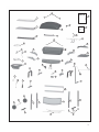
PARTS
LIST
Item No.
Description
Part No.
AA
Quantity
1
/«Ê`
G437-0026-01
AB
1
>`iÊ/«Ê`
G306-0002-01
AC
1
Thermometer
G305-0039-01
AD
2
1««iÀÊ
}i
G436-0042-01
BA
1
ÕÀiÀÊÝÊÃÃiLÞ
G437-1301-01
BB
1
Burner
G437-0100-01
BC
1
iVÌÀ`iÊÜÉÊÜÀi]Ê}ÌiÀ
G305-0026-02
BD
1
Flame tamer
G434-0005-01
1
Cooking Grate
G434-0004-01
BF
1
7>À}Ê,>V
G437-0032-02
BG
2
ÜiÀÊ
}i
G210-0019-01
1
i>ÌÊ-
i`
G434-0009-01
CA
1
ÌÀÊ*>i
G434-0041-01
CB
1
*ÕÃ
ÊÕÌÌÊ}ÌiÀ
G206-0301-01
CC
3
Control Knob
G401-0023-01
CD
1
6>ÛiÊÃÃiLÞ
G434-0600-01
1
Ài>ÃiÊVÕ«Ê
G401-0067-01
CF
1
Ài>ÃiÊVÕ«
G430-0033-01
CG
1
iÌ>ÊÃi
G305-0015-01
1
-`iÊÕÀiÀÊ6>Ûi
G304-0036-01
1
,i}Õ>ÌÀ
G402-0069-01
DA
1
,}
ÌÊÃ`iÊÃ
iv
G305-0300-01
DB
2
,}
ÌÊ-`iÊ-
ivÊÀ>ViÌÊ£Ê
G305-0034-01
DC
2
ivÌÊ-`iÊ-
ivÊÀ>ViÌÊÓÊ
G305-0033-01
DD
1
ÕÀiÀÊÝÊ-Õ««ÀÌÊ,}
Ì®
G305-0031-02
1
ÕÀiÀÊÝÊ-Õ««ÀÌÊivÌ®
G305-0030-02
DF
1
ivÌÊÃ`iÊÃ
iv
G434-3400-01
DG
1
-`iÊÕÀiÀÊÀ«Ê*>
G304-0016-01
1
-`iÊÕÀiÀÊiVÌÀ`iÊÜÉÊÜÀi
G434-0040-01
1
Side Burner
G437-3400-01
DJ
1
Side Burner Cooking Grate
G303-0022-01
2
,i>ÀÊÀ>Vi
G434-0006-01
1
1««iÀÊÀÌÊ*>i
G434-2501-01
1
/>ÊiÝVÕÃ]ÊÜÀiÊvÀ>i
G434-0010-01
FA
2
1««iÀÊi}Ê-Õ««ÀÌÊ>À
G305-0600-01
FB
1
>VÊ,}
ÌÊ
>ÀÌÊi}
Îäxää£nä£
FC
1
ÀÌÊ,}
ÌÊ
>ÀÌÊi}
G305-0017-01
FD
1
>VÊivÌÊ
>ÀÌÊi}
G305-0020-01
1
ÀÌÊivÌÊ
>ÀÌÊi}
G305-0019-01
FF
2
`Ê
>«Ã
Óänää£Óä£
FG
2
Bottom Brace
G305-0021-01
2
7
iiÃ
G206-0025-01
G305-0023-01
1
7
iiÊÝi
FJ
1
Side Brace
G305-0700-01
FK
1
/>Ê,iÌiÌÊÀ>ViÌ
G306-0020-01
For product inquires, parts, and
1
>ÌV
Ê`iÀ
G401-0079-01
warranty and troubleshooting
FM
1
>À`Ü>ÀiÊ«>V
G434-B006-01
1
User manual
G434-M006-01
support, please call 1-877-707-5463.
12
AD
Manual
FM
BF
AC
BE
Hardware
Pack
AA
BC
AB
BD
FN
BB
BG
DJ
BH
DI
BA
DC
DB
DH
DA
DB
DC
CA
DG
Cᷩ
DF
CB
CD
CC
FA
DE
DD
FA
CE
Cᷨ
CC
CF
FL
FK
FJ
Cᷪ
EA
FH
FI
FB
FC
EB
FH
FE
FD
FG
FG
EC
FF
13
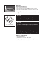
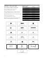
A S S E M B LY I N S T R U C T I O N S
Hardware Pack List
Key No.
Description
Par t Number
Tools needed for assembly are shown below.
1
1/4"-20UNC X13 Screw
20120-13013-036
Quantity
2
1/4"-20UNC X30 Screw
20120-13030-036
4
Before assembling the barbecue, please ensure
that you have all the hardware needed.
3
1/4"-20UNC Nut
31220-13000-036
4
4
NO.10-24UNCx13Screw
20124-10013-036
30
5
NO.10-24 X30 Screw
20124-10030-036
16
4
6
NO.10-24X50 Screw
20124-10050-036
8
Before assembling the barbecue, read these instructions
carefully. Assemble the barbecue on a flat, clean surface.
7
NO.10-24UNC Nut
31224-10000-036
42
8
NO.8-32UNC X10 Screw
20132-08010-036
2
9
ST4.2X10 Tapping Screw
22500-42010-136
3
Note: Do not fully tighten all the nuts during initial stage.
10
NO.8-32 UNC Wing Nut
33300-08000-032
1
11
NO.10-24UNC Wing Nut
33300-10000-036
2
12
Fibre Washer A
G437-0049-9000
4
13
Fibre Washer B
G437-0050-9000
20
14
Wheel Bushing (washer)
G305-0024-9088
1
Grill is heavy. You should have two
people assemble the barbecue together.
Please refer to the part numbers underneath the hardware
name for use when ordering parts under warranty.
Key #1: 1/4”-20UNCX13 Screw (x4)
15
Hitchpin
G306-0005-9088
5
16
Hinge
G306-0004-9188
4
17
Wing Screw,#10-24X3/8
G306-0025-9084
1
18
Clip, Venturi, Sideburner
G305-0057-9000
1
19
Washer,for Lid Handle
G306-0027-9300
2
Key #2: 1/4”-20UNCX30 Screw (x4)
Key #4: No10-24UNCX13 Screw (x30)
Key #5: No10-24UNCX30 Screw (x16)
Key #6: No10-24UNCX50 Screw (x8)
Key #7: No10-24UNC Nut (x42)
Key #8: No8-32UNCX10 Nut (x2)
Key #9: ST4.2X10 Tapping Screw (x3)
Key #10: No8-32UNC Wing Nut (x1)
Key #11: No10-24UNC Wing Nut (x2)
Key #12: Fiber Washer A (x4)
Key #13: Fiber Washer B (x20)
Key #14: Wheel Bolt Washer (x1)
Key #15: Hitchpin (x5)
Key #16: Hinge (x4)
Key #17: No10-24UNC Wing Screw (x1)
Key #18: Side burner Venturi clip (x1)
Key #19: Fibre Washer for handle (x2)
14
Key #3: 1/4”-20UNC Nut (x4)
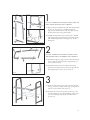
Left
Figure A
FA
Upper Left Leg
FJ
Lower Left Leg
FD
9
10
1B. Assemble the bottom brace (FG) (with notches to hold LP
tank facing upwards) to both the front and rear left cart legs
(FD and FE) using hardware #16 hinge pin (2) and #15
hitch pin (2).
Notchs to hold LP cylinder
Tank Support Bracket
Right
DO NOT COMPLETELY TIGHTEN SCEWS UNTIL ALL
PARTS ARE IN POSITION AND CORRECT.
1A. All parts must be assembled at the same time using hardware
#5 screw (2) and #7 nut (2). Assemble the upper leg
support (FA), with the side brace (FJ) in position, to both
the front and rear left cart legs (FD and FE).
FE
FG
1
Figure B
FC
FG
FA
2
DO NOT COMPLETELY TIGHTEN SCREWS UNTIL
THE ENTIRE CART IS ASSEMBLED AND CORRECT.
2A. Assemble the upper leg support (FA) to the both the front
and rear right cart legs (FB and FC) using hardware #5
screw (2) and #7 nut (2).
FB
Figure B
2B. Assemble the bottom brace (FG) (with notches facing
downward) to both the front and rear left cart legs (FD and
FE) using hardware #5 screw (2) and #7 nut (2).
Figure A
Support Bracket
3
EA
3A. Attach the tank exclusion wire (EC) to the left and right
cart legs, as shown, ensuring that the large opening for the
tank is located on the left side of the cart.
FB
FD
3B. Assemble one of the rear braces (EA) in this step, to the
rear left and right cart legs (FD and FB) by removing the
two screws and flange nuts already assembled in the
previous step.
EC
Back view
15
Right
EA
Left
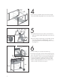
4
Position the front panel (EB) in between the front left and right
cart legs and assemble using hardware #6 screw (4) and #7 nut (4).
EB
5
EA
FB
Right
FH
5A. Assemble the bottom rear brace (EA) to the back left and
right cart legs (FB and FD) using hardware #5 screw(4) and
#7 nut (4).
FH
FI
Left
FD
Control Panel (CA)
5B. Insert the wheel axle (FI) through one wheel (FH), through
the cart leg and into the second wheel (FH). Secure in
position using hardware #14 wheel bushing washer (1) and
#15 hitchpin (1).
6
You must assemble parts at the same time in this step.
Position the control panel onto the front left and right upper leg
support (FA) using hardware #6 screw (4) to keep it in position.
Do not attach nut yet. Next, position the left and right burner
box support (DD and DE) as shown in the image. Complete
control panel assembly by using hardware #7 nut (4) to affix
hardware. Finally using hardware #6 screw (4) and #7 nut (4)
complete assembly of the burner box supports.
DD
CA
Right
Back view
16
DE
Left
CB
CD
CH
Right
7
7A. Attach the valve assembly (CD) to the control panel using
hardware #4 screw (2).
Left
7B. Unscrew the nut found on the push button ignitor (CB) and
secure it to the control panel.
Back view
BH
Left
8
Attach the heat shield (BH) to the left side of the cart using #4 (×2)
and #7 (×2).
Note: regulator and hose come out by heat shield.
9
Insert the tank retention bracket (FK) into the side brace (FJ) and
secure using hardware #17 Wing screw (1).
FJ
FK
17
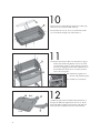
10
BB
BA
Place the burner assembly (BB) into the burner box (BA) using
hardware #4 screw (2) and #13 Fiber washer(2).
Insert hardware #5 screw (4), #7 nut (4) and #13 fiber washer
(4) to both the left and right sides of the burner box.
11
BA
CC
11A. Position the burner box (BA) onto the burner box support
brackets (DD & DE) using hardware #4 screw (4), #7nut
(4) and #13 fiber washer (4). Ensure that the gas jets from
the valves are engaging the burner tubes. If the burner is not
horizontally leveled, adjust the two screws that attach the
valve to the control panel.
11B. Attach the short igniter wire to
the back of the push button igniter.
11C. Assemble the control knobs.
lve
Va
DA
Back
DB
be
Burner Tu
Short Ignitor Wire
12
Assemble the right and left side shelf brackets (DB and DC) to
the right side shelf (DA) using hardware #4 screw (4). Ensure
that bracket DB is assembled to the back side of the shelf, and
that bracket DC is assembled to the Front of the side shelf.
Front
18
DC
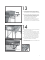
13
13A. Attach the assembled right side shelf (DA) to the front cart
leg using hardware #1 screw (2), and using hardware #2
screw (2) and #3 nut (2) to attach the back of the side shelf.
DA
13B. Assemble the right and left side shelf brackets (DB and
DC) to the left side shelf (DF) using hardware #4 screw
(4). Ensure that bracket DC is assembled to the back
side of the left side shelf, and that bracket DB is
assembled to the Front of the left side shelf.
Attach the assembled left side shelf (DF) to the front cart
leg using hardware #1 screw (2), and using hardware #2
screw (2) and #3 nut (2) to attach the back of the side shelf.
DI
14
DG
14A. Insert the side burner drip pan (DG) and assemble using
hardware #9 (x3) and #12 (x3).
14B. Insert the side burner valve through the back of the side
burner control panel and attach using hardware #8 (x2).
14C. Insert the side burner into the left side shelf making sure
that the burner tube fits directly over the side burner
valve. Secure the burner in place using hardware #10
wing nut(1) and #12 fiber washer (1). See Figure 14d.
14d.
14D. Using the Burner Clip hook included with hardware
pack secure the side burner to the manifold.
14E. Attach the side burner igniter wire from the igniter to the
side burner electrode.
Hook burner clip
19
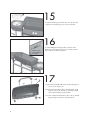
15
DJ
Attach the remaining control knob (CC) onto the valve stem
and place the side burner grate (DJ) onto the side shelf.
CC
16
Figure B
Center flat portion
of hinge should be
at the bottom.
Attach the BBQ lid lower hinges (BG) to the back of the
Burner box using hardware #4 screw (4), #7 nut(4) and #13
fiber washer(4), as shown in Figure B.
Back view
AB
AA
17
17A. Attach the lid handle (AB) to the top lid (AA) using #11
(×2), #13 (×2) and #19 (×2).
17B. Attach the upper hinges (AD) to the back of the top lid
using #4 (×4), #7 (×4) and #13 (×4). The hinges should
curve downward when properly installed.
AD
20
17C. Next, assemble the thermometer (AC) to the top lid (AA)
using the wing nut attached to the thermometer.
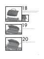
18
Place the lid assembly onto the fire box. Secure the upper and
lower hinges using #15 hitchpin (x2) and #16 hinge (x2).
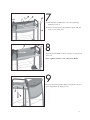
19
Place the flame tamer (BD) into the fire box.
BD
20
Place the cooking grate (BE) onto the fire box.
BE
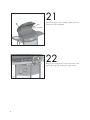
21
21
BF
Pivot
Insert the pivot leg wire of the warming rack (BF) in the holes,
located on the side of the grill lid.
leg wire
22
Hang the grease cup hook (CF) to the bottom of fire box and
place the grease cup (CE) into the grease cup hook (CF).
CF
CE
22
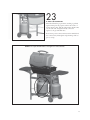
23
LP TANK IS SOLD SEPARATELY.
Fill and leak check the propane before attaching to grill and
regulator. Then place the propane tank into the notches of
the bottom brace (FG). Slide the tank retention bracket (FK)
over the tank collar and tighten. Finally, connect the
regulator to the gas tank OPD valve.
Please ensure positive connections between the manifold and
hose connections by hand tighten and performing a leak test
prior to start up.
NEVER store a spare LP tank under or near grill or in enclosed areas.
23
24

![[MAS 010] G30505 BBQ Manual F](http://vs1.manualzilla.com/store/data/006315885_1-7931826f9e191de9865bd3eb444d7265-150x150.png)