1
13
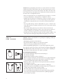
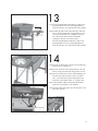
13A. Attach the assembled right side shelf (DA) to the front cart
leg using hardware #1 screw (2), and using hardware #2
screw (2) and #3 nut (2) to attach the back of the side shelf.
DA
13B. Assemble the right and left side shelf brackets (DB and
DC) to the left side shelf (DF) using hardware #4 screw
(4). Ensure that bracket DC is assembled to the back
side of the left side shelf, and that bracket DB is
assembled to the Front of the left side shelf.
Attach the assembled left side shelf (DF) to the front cart
leg using hardware #1 screw (2), and using hardware #2
screw (2) and #3 nut (2) to attach the back of the side shelf.
DI
14
DG
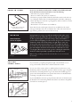
14A. Insert the side burner drip pan (DG) and assemble using
hardware #9 (x3) and #12 (x3).
14B. Insert the side burner valve through the back of the side
burner control panel and attach using hardware #8 (x2).
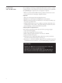
14C. Insert the side burner into the left side shelf making sure
that the burner tube fits directly over the side burner
valve. Secure the burner in place using hardware #10
wing nut(1) and #12 fiber washer (1). See Figure 14d.
14d.
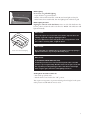
14D. Using the Burner Clip hook included with hardware
pack secure the side burner to the manifold.
14E. Attach the side burner igniter wire from the igniter to the
side burner electrode.
Hook burner clip
19