1
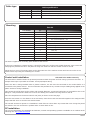
Cable type
Cable specification
Use
Max length
RS485 Data Line
1000 yds
Reader / Keypad
500 feet
Input / Output
100 yds
Type
2 x twisted pairs - Belden 8723 or Cat5 equivalent
8 core, shielded - Beldon 9538, Alpha 1298C (22AWG) or equivalent
2 conductor - Alpha 1172C (22AWG) or equivalent
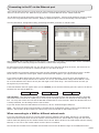
Mounting
Parts kit
Part Number
Qty
Fitting Kit fk1-108
1
Ferrite tube
1
Grommet, 22mm hole
3
Wall plugs
3
Pozi round woodscrew - zinc
1
Pozi panhead lid screw
1
Rubber washer
1
Cable gland
1
Cable gland lock nut
4
Cable clip
10
Cable tie
Fitting Kit fk1-039
Description
1
1N4001 diode
4
120 ohm Resistor 1/4W
2
Cable tie
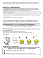
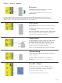
The ACU is supported on mounting posts located at the corners.
If the unit is supplied in a plastic housing, it should be fixed to the surface with suitable fasteners. Four screws and
wall plugs are provided for this in the parts kit along with cable ties and two smaller screws for the lid.
Mount the four corner f/f mounting posts to the plate with four of the machine screws and then secure the circuit
board to their tops using the remaining four screws.
Control unit installation
This unit is for Indoor use only
The ACU shall be installed within the protected premises as both the power and lock wiring is present at the PCB.
Tamper alarm input is provided on the PCB - See Input/Output Wiring
A
Where the ACU is being installed within a plastic enclosure, the hub must be connected to the conduit before it is
connected to the plastic enclose. This is to eliminate the potential of any excessive torque loading being applied to the
plastic enclosure during installation.
This housing should be fixed to the surface with suitable fasteners; screws and wall plugs are provided for this in the
fitting kit. Also provided are cable ties to secure the cabling and a smaller securing screw for the lid.
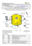
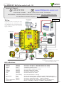
Wire the components to the Access Control Unit (ACU) as shown on the first page.
Press the exit button or in the absence of an exit button, short the 0V and exit terminals together. The configured lock
output LED will come on and the lock should release.
The unit will continue to operate in a 'standalone' mode if the PC is shut down. Any Events that occur during this period
are stored in the unit and the PC is updated when it comes back on line.
PC installation
The current specification for compatible PC hardware, network and operating systems is available on our website at the
following link: http://paxton.info/720
PAGE 3