1
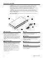
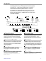
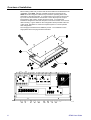
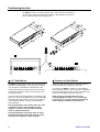
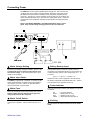
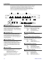
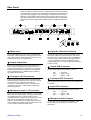
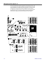
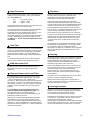
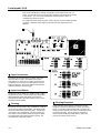
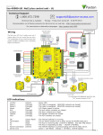
ALLEN&HEATH
GR05
Audio Zone Mixer
Introduction ......................... 3
Welcome to the GR05 ......... 4
22 M
Miiccrroopphhoonnee IInnppuuttss
33 S
Stteerreeoo LLiinnee IInnppuuttss
44 ZZoonnee O
Ouuttppuuttss
R
Roouuttiinngg M
Maattrriixx
R
Reem
moottee C
Coonnttrrooll
The System.......................... 5
D
Duucckkiinngg
E
Exxppaannddeerr
Level Control........................ 16
Overview of Installation ....... 6
Positioning the Unit ............. 8
Connecting Power............... 9
Front Panel .......................... 10
Rear Panel ........................... 11
Mic/Line Inputs .................... 12
Line Inputs ........................... 14
Outputs ................................ 15
Remote Control ................... 17
Ducking................................ 18
IInnssttaalllleerr A
Assssiiggnnaabbllee
Expander In/Out .................. 20
Specification ........................ 21
Block Diagram ..................... 22
Configuration Sheet............. 23
USER GUIDE
INSTALLATION
Publication AP3181
Limited One Year Warranty
This product is warranted to be free from defects in materials or workmanship for
a period of one year from the date of purchase by the original owner.
To ensure a high level of performance and reliability for which this equipment has
been designed and manufactured, read this User Guide before operating. In the
event of a failure, notify and return the defective unit to Allen & Heath Limited or
its authorised agent as soon as possible for repair under warranty subject to the
following conditions
Conditions Of Warranty
1. The equipment has been installed and operated in accordance with the instructions in
this User Guide
2. The equipment has not been subject to misuse either intended or accidental, neglect, or
alteration other than as described in the User Guide or Service Manual, or approved by
Allen & Heath.
3. Any necessary adjustment, alteration or repair has been carried out by Allen & Heath or
its authorised agent.
4. The defective unit is to be returned carriage prepaid to Allen & Heath or its authorised
agent with proof of purchase.
5. Units returned should be packed to avoid transit damage.
In certain territories the terms may vary. Check with your Allen & Heath agent for any
additional warranty which may apply.
This product complies with the European Electromagnetic Compatibility
directives 89/336/EEC & 92/31/EEC and the European Low Voltage
Directives 73/23/EEC & 93/68/EEC.
NOTE: Any changes or modifications to the unit not approved by Allen & Heath could void the
compliance of the unit and therefore the user’s authority to operate it.
GR05 User Guide AP3181 Issue 5
Copyright © 2008 Allen & Heath Limited. All rights reserved
Whilst we believe the information in this guide to be reliable we do not assume responsibility for
inaccuracies. We also reserve the right to make changes in the interest of further product
development.
Allen & Heath Limited
Kernick Industrial Estate,
Penryn, Cornwall, TR10 9LU, UK
http://www.allen-heath.com
2
GR05 User Guide
Safety Warning !
Do not remove the cover while mains is connected. Mains voltage is dangerous
and can kill. Mains voltage is present within the unit. Do not carry out any work within the unit
while it is powered except for installation calibration. High voltage components are insulated for
safety but should not be touched with power applied. Do not attempt to remove the main circuit
assembly from the chassis. Refer service work to qualified service personnel only.
This equipment must be earthed. To ensure your safety the mains earth is connected to
the chassis through the power lead. Do not remove the mains earth connection.
Important Mains plug wiring instructions.
The console is supplied with a moulded mains plug fitted to the AC mains power lead. Follow the
instructions below if the mains plug has to be replaced. The wires in the mains lead are coloured
in accordance with the following code:
TERMINAL
WIRE COLOUR
European
USA/Canada
L
LIVE
BROWN
BLACK
N
NEUTRAL
BLUE
WHITE
E
EARTH GND
GREEN & YELLOW
GREEN
The wire which is coloured Green and Yellow must be connected to the terminal in the plug which
is marked with the letter E or with the Earth symbol. This appliance must be earthed.
The wire which is coloured Blue must be connected to the terminal in the plug which is marked
with the letter N.
The wire which is coloured Brown must be connected to the terminal in the plug which is marked
with the letter L.
Precautions
Mains Voltage
Moisture
The mains voltage setting is factory wired and is marked
on the rear panel. Check that this matches your local
mains supply. Ensure that the mains lead is fitted with
the correct safety approved mains plug.
Avoid liquid spillage and exposure to rain and moisture.
Should the unit become wet switch off and remove
mains power immediately. Allow the unit to dry out
completely before switching on again.
Ventilation
Cleaning
The rear panel and top panel may run slightly warm.
This is normal. Do not completely cover the unit. Ensure
that there is adequate air flow around the unit.
Avoid the use of chemicals, abrasives and solvents. The
panels are best cleaned with a soft brush and dry lintfree cloth.
Operating Environment
Audio Connections
Protect from excessive dirt, dust, heat or cold and
vibration when operating, shipping or storing the unit.
Do not connect sources of AC or DC power or the output
of power amplifiers directly to the audio input or output
connectors.
GR05 User Guide
3
Welcome to the GR05
The GR05 is a 1U rack or desk mount audio zone mixer for installation applications such as
paging and background music systems in restaurants, retail outlets, leisure centres, clubs,
theatres, business offices etc. It has a flexible architecture which allows easy custom
configuration by the installer to exactly suit the requirements of the installation. Once installed it
presents a simple control interface for day to day operation by non-technical staff.
The GR05 has 2 microphone inputs and 3 stereo line inputs. These can be assigned to 4 zone
outputs configurable in mono or stereo pairs and controlled by front panel or remote level
controls. Ducking, EQ and muting can be configured. Further inputs and outputs are available
using the expander system.
The next page summarises the facilities which can be configured by the installer to satisfy the
needs of the installation.
Control Panel
page 10
This has a simple layout for easy day to day control of
audio levels and zone switching by non-technical
operators. 3-colour LED indicators provide dynamic
indication of signal levels and system status.
The installer decides which controls are available to the
operator. Others can be removed, configured as preset
trimmers or locked out to prevent accidental operation.
Large write-on blocks allow custom identification of the
controls.
Connector Panel
11
Pluggable connectors are provided for all audio inputs
and outputs, the expander / remote facility, and mains
input. This allows the unit to be installed and removed
independent of the wiring harnesses.
The mains power switch is rear panel mounted to
prevent illegal operation. The unit serial number and
mains voltage setting is marked on the rear panel.
Gain trimmers are included to match the microphone
levels to the unit. These can be
Cover
6
The top cover is removable to allow the installer to
configure the internal links and trimmers. Once
configured, the cover must be refitted.
Rack Ears
8
The two rack ears allow the unit to be mounted in a
standard 19” rack case along with other equipment in
the system. For desktop operation these may be
unscrewed and removed.
Plastic Feet
8
A set of plastic feet is fitted to the unit for desktop use.
These may be removed if required for rack mounting.
Hole Plugs
10
A bag of hole plugs is provided for front and rear panel
control lockout. Control knobs may be removed and the
front panel holes plugged to prevent the operator
changing the settings.
configured for easy knob access, preset trimmers, or
locked out once set.
4
GR05 User Guide
The System
The following diagram shows the GR05 in a typical sound contractor installation.
This combines paging microphones with background music sources feeding up
to 4 speaker zones. An alarm interface and battery backup are included to
ensure crowd control in the event of a fire or power failure. Remote level
controls are wall mounted for local speaker control.
Each installation has its own particular combination of input/output and control
requirements. For this reason the GR05 offers a uniquely flexible architecture
that can be installer configured for each application. We recommend that you
take time to fully understand the full capabilities of this unit and carefully plan the
most suitable configuration.
ALLEN&HEATH
GR05
mic/line 1
mic/line 2
st line 3
st line 4
st line 5
out 1
out 2
out 3
out 4
mute
ducking
power
AUDIO ZONE MIXER
Paging Microphone
12,18
This is the microphone used by the receptionist to call
for or ‘page’ staff or customers. It is set so that speaking
into the mic automatically overrides the background
music by reducing its level. This is known as ‘voiceover’
or ‘ducking’.
Announcement Microphone
12,18
Similar to the paging mic but usually kept behind the bar
or counter for occasional announcements or special
function use. Can be set to duck music sources, or be
itself ducked by the announcer for example when being
used as the karaoke mic.
Line Inputs
14
19
The jukebox provides music selected and paid for by the
customer. As such it is a priority source that
automatically overrides any other background music
playing at the time.
GR05 User Guide
19
It is often a safety requirement to link the audio system
to the fire alarm for automatic playback of an evacuation
message should the alarm be triggered. The prerecorded signal would override any background music
source.
Power Input
9
The GR05 has a built in mains operated power supply.
An additional input is provided to connect a backup
supply such as a battery unit which automatically takes
over should the mains power fail. This is important when
the unit is linked to an alarm system as described above.
Remote Level Control
17
+10V DC control inputs allow the GR05 VCA output
levels to be adjusted by volume controls positioned
away from the unit such as wall plates.
These are commonly the cassette or CD inputs for
background music. They may be stereo or mono.
Jukebox
Evacuation Alarm
Zone Outputs
15
These provide 4 separate feeds to the amplifiers driving
the speakers in different areas or ‘zones’.
5
Overview of Installation
Before starting make sure you have read this User Guide and understand the full
capabilities of the GR05. Plan the complete system first to decide how the
GR05 should be configured. Make sure you know the operating levels of the
equipment to be interconnected. To configure the unit you need to remove the
top cover and set internal links and trimmers. These adjust input and output
level matching, EQ, routing, ducking and level control. To complete the
installation configure the front and rear panel controls and set the unit for rack or
desk mounting. Log the details on the Configuration Sheet provided at the rear
of this guide. Remember to check the complete system for correct operation
after configuration.
The next page summarises the installation process. For full details on each
stage please refer to the page numbers indicated.
6
GR05 User Guide
Rack or Desk Mount
8
The GR05 is shipped with the two rack ears and its
plastic feet fitted. The unit will fit into a 1U space in a
standard 19” industrial rack case. Use the bolts
provided by the rack supplier to mount the unit in the
rack. Remove the feet if required. You can also use the
rack ears to mount the unit into a plinth.
For desktop or shelf operation the rack ears can be
removed. The plastic feet prevent the unit scratching the
mounting surface or slipping.
Plug up the Connectors
9,12-20
The wiring harnesses can be prewired and installed
before the unit is put in place. All connections are
pluggable. Connector types are 3-pin XLR for the
microphone inputs and zone outputs, RCA phono for the
stereo line inputs, and 25-pin D-type for the
expander/remote and battery interface. The mains input
is on standard 3-pin IEC connector.
Make sure that you allow enough length in the cables for
the unit to be removed for configuration.
Assign the Controls
10,11
The GR05 front panel level controls and rear panel gain
trimmers may be set in 3 ways: The knob is fitted for
user control, the knob may be removed so that it
becomes a preset trimmer adjustable using a slotted
screwdriver, or a plug may be fitted locking the control
so that it cannot be adjusted by the operator. It is
important to assign these so that the operator has
access only to those controls which need adjusting
during normal daily operation.
Front panel ident blocks are provided so that the
controls can be identified according to the application.
These can be marked using permanent pen, or adhesive
labels.
Remove the Cover
Switch off mains power before removing the cover.
To gain access to the configuration links and trimmers
remove the 8x M3 T10 Torx head screws and lift the top
cover away from the unit. Power may be re-applied while
adjusting the internal trimmers. Avoid the internal
power supply components. There are no adjustable
parts in the power supply.
Microphone Inputs 1,2
12
A balanced XLR input for each accepts a microphone or
mono line level signal. Adjust the sensitivity using the
rear panel gain trimmer. Use the meter LED to check for
correct signal level. Internal links provide options for an
attenuator pad, phantom power and lo-cut filter. Internal
trimmers adjust the EQ providing control of the low
frequency and mid/high frequencies, ideal for optimising
the tonal response of speech microphones.
GR05 User Guide
Line Inputs 3,4,5
14
Each has a pair of RCA phono sockets for Left and Right
inputs. For mono sources only one need be used. To
mono a stereo source use the routing options as
described below. Use the internal jumper links to set the
sensitivity for high level +4dBu or low level –10dBV
equipment. Check for correct signal level using the
meter LEDs.
Routing Matrix
12,14
Internal link options let you route any input to any
combination of outputs. For example a stereo line input
could be routed to outputs 1 and 2 in mono and to
outputs 3 and 4 in stereo, or a microphone could be
routed to just one zone only. For each input to each
output set the link to ‘OFF’ for no routing, ‘VCA’ for
routing with level control and ducking, or ‘DIRECT’ for
routing without level control or ducking.
Outputs
15
The 4 outputs are line level on 3-pin XLR impedance
balanced connectors for interference rejection on long
cable runs. These have internal trimmers that adjust
between –10dBV low level and +4dBu high level for
signal matching and balance control. A 2band EQ with
internal trimmers lets you adjust the low and high
frequency response to match the speakers or room
acoustics. This can also be used to compensate for the
loudness effect when playing background music at low
volume.
Level and Ducking
16-19
Signals routed direct to the outputs are not affected by
level control or ducking. These would include paging
microphones, jukebox playback and alarm messages.
Signals routed through the VCAs to the outputs are
affected by level control and ducking.
Internal link options for each output determine whether
the level is controlled from the front panel or by +10V
remote. Front panel controls can be grouped for single
control of several outputs, for example a stereo zone.
The front panel mute switch can be set to control any
combination of outputs.
Internal and external ducking can be separately
configured to affect any combination of outputs. Internal
ducking is triggered by setting links for Mic1 or Mic2 or
both. Option links separately set internal and external
ducking depth and release time. Ducking can be set to
mute rather than reduce the signal, for example with
jukebox override.
Completion
After configuring the unit check the system for correct
operation. Refit the cover. Log the details on the
Configuration Sheet provided at the rear of this Guide.
7
Positioning the Unit
The GR05 is built into a compact all steel case. This can fit into a standard 1U
19” rack space with the mounting ears provided. Alternatively the unit can be
desk or shelf mounted by removing the ears.
ALLEN&HEATH
GR05
mic/line 1
mic/line 2
st line 3
st line 4
st line 5
out 1
out 2
out 3
out 4
mute
ducking
power
AUDIO ZONE MIXER
19” Rack Mount
The GR05 is shipped with the two rack mount ears and
its plastic feet already fitted. The unit may be mounted
in a 1U space in a standard 19” industrial rack case.
If space below the unit is tight, remove the feet using a
small slotted screwdriver to prise out the plastic rivets
from within the feet.
Use the mounting fixings provided by the supplier of the
rack case. These are usually black or chrome plated M6
bolts that seat in black plastic cups to prevent damage
to the equipment panels. All four mounting fixings
should be fitted.
ALLEN&HEATH
GR05
mic/line 1
mic/line 2
st line 3
st line 4
st line 5
out 1
out 2
out 3
out 4
mute
ducking
power
AUDIO ZONE MIXER
Desktop or Shelf Mount
Desktop or shelf mounting may be required where the
unit is operated by a receptionist or bar staff.
To configure the GR05 for desktop or shelf mounting
remove the two rack ears. Use a T10 Torx screwdriver to
remove the 3 M3 fixing screws on each side. Ensure the
4 plastic feet are fitted to the base of the unit.
Allow enough space behind the unit for the
connecting plugs and cables. Do not completely
cover the unit. To prevent excessive heat build up
ensure adequate ventilation around the unit.
Avoid positioning the unit or audio cables too close
to equipment such as power amplifiers, power
supplies or computer monitors which emit high
levels of radiated interference.
Avoid positioning the unit directly above or below
equipment which generates large amounts of heat
such as power amplifiers or power supplies.
8
GR05 User Guide
Connecting Power
The GR05 has a built in mains operated power supply unit. This converts and
conditions the mains voltage to the DC voltages required to power the circuits.
An additional DC power input is available on the rear panel expander/remote
connector. This lets you connect a backup power supply such as a battery unit
which automatically takes over in the event of a mains power failure. Check the
requirements of the installation regarding the specification of safety and power
systems.
Refer to the SAFETY WARNING ! and PRECAUTIONS on page 3 of this
guide. Also read the safety warnings printed on the rear of the unit.
47-63Hz~ V.AC
WARNING
THIS APPARATUS MUST BE EARTHED.
CAUTION: RISK OF ELECTRIC SHOCK. HIGH VOLTAGE INSIDE.
AVIS: RISQUE DE CHOC ELECTRIQUE
ALLEN&HEATH
GR05
EXPANDER / REMOTE
18W MAX
S/No
100-120V ~ = T630mAL 250V 20mm
220-240V ~ = T315mAL 250V 20mm
FUSE
CONFORMS TO UL STD. 6500
CERTIFICATED TO CAN/CSA STD. E60065
ducking
Mains Voltage Setting
The factory set voltage setting is marked in this box. Do
not switch the unit on if this is not the same as your
local mains voltage. In this event please refer to your
dealer or service agent.
Mains Input Cable
The GR05 is supplied with a separate 1.8 metre long IEC
mains cable with fitted moulded mains plug suitable for
the supply in your area. If this is not the case please
refer to your dealer or service agent.
Mains Fuse
This fuse provides protection should the power unit fail.
Always replace this fuse with the correct type and
rating as specified on the rear panel.
Mains On/off Switch
This switch is rear panel mounted to prevent accidental
or illegal user operation. Press to switch the unit on or
off.
GR05 User Guide
power
Battery Backup Input
The expander/remote connector includes 3 pins for
connection to an external dual rail DC power supply unit
or battery backup system. Input voltage range is +/- 12
to 15V DC:
pin13 = +V, pin12 = -V, pin25 = 0V
Should the mains power supply fail or be switched off
the backup supply will automatically take over. There is
no interruption to the operation of the unit.
Power Indicator
The front panel power indicator LED displays four power
conditions:
Off
Green
Red
Yellow
=
=
=
=
No power applied
Mains power on only
Backup power on only
Mains and backup power on
Earthing
Do not remove the earth connection from the mains
cable.
9
Front Panel
The front panel control layout is deliberately uncluttered and simple. These are
the controls that are used by the non-technical operator who does not need to
understand how the unit has been configured or what the controls do
technically. Control function and access can be configured by the installer. A
row of 3-colour LED indicators display the signal levels and system status.
These are invaluable for system setup and diagnostics.
ALLEN&HEATH
GR05
mic/line 1
mic/line 2
st line 3
st line 4
st line 5
out 1
out 2
out 3
out 4
mute
ducking
power
AUDIO ZONE MIXER
ALLEN&HEATH
GR05
mic/line 1
mic/line 2
st line 3
st line 4
st line 5
out 1
out 2
out 3
out 4
mute
ducking
power
AUDIO ZONE MIXER
Mic/Line Inputs 1,2
The sensitivity of the input stage is matched to the
connected microphone using the rear panel gain
trimmer. The front panel level control adjusts the level of
the signal to all routed outputs. Fully anti-clockwise is
signal off, clockwise signal on. A 3-colour LED displays
pre-level input signal status.
Line Inputs 3,4,5
The sensitivity of the input stage is matched to the
connected equipment using the internal jumper links.
The front panel level control adjusts the level of the
signal to all routed outputs. Fully anti-clockwise is signal
off, clockwise signal on. A 3-colour LED displays prelevel input signal status.
Zone Outputs 1,2,3,4
These front panel controls adjust the level of the output
signal routed through the VCA paths. Fully anticlockwise is signal off, clockwise signal on. They may
be disabled, for example when using remote level
control. They may also be linked for stereo or group
control. A 3-colour LED displays post-level output
signal status.
Level Control
Input level controls are always active. Output level
controls may be disabled or grouped by internal links.
All controls may be set in 3 ways:
Knob fitted for operator control
Knob removed for screwdriver preset
Hole plug fitted to lock out control
To remove the knob simply pull it forwards. To refit the
knob align the knob hole with the flat on the control
spindle.
10
Signal Meter
A 3-colour LED meter for each input and output displays
the signal level. Input signals are displayed before the
level control, output signals after the level control.
Green = Signal present (from –12dB)
Yellow = Nominal 0dB signal
Red
= Peak 5dB before clipping
Control Ident Blocks
These blocks can be marked or labelled for control
identification.
Output Mute switch and Indicator
This front panel switch turns the outputs on or off. The
switch function can be disabled for selected outputs by
setting internal option links.
Off
= Switch disabled
Green = Selected outputs on
Red
= Selected outputs muted (off)
Ducking Status Indicator
Displays the status of the ducking system.
Off
= No ducking active
Green = Internal ducking only active
Red
= External ducking only active
Yellow = Both internal and external active
Power Status Indicator
Displays the status of the power system.
Off
= No power applied
Green = Mains power on only
Red
= Backup power on only
Yellow = Mains and backup power on
GR05 User Guide
Rear Panel
The audio input and output connectors, expander/remote interface connector,
and mains input connector, fuse and switch are located on the rear panel. All
connections are pluggable to allow pre-wiring of the cables before the unit is
installed. The microphone input gain trimmers are also located on the rear to
allow easy readjustment of mic sensitivity by the installer but not the operator.
The factory set mains voltage and unit serial number are marked on the rear
panel.
47-63Hz~ V.AC
WARNING
THIS APPARATUS MUST BE EARTHED.
CAUTION: RISK OF ELECTRIC SHOCK. HIGH VOLTAGE INSIDE.
AVIS: RISQUE DE CHOC ELECTRIQUE
LINE
OUT
ALLEN&HEATH
GR05
4
3
2
1
LINE
IN
5
L
4
L
3
L
2
GAIN
MAX
EXPANDER / REMOTE
18W MAX
R
R
MIC/LINE IN
1
GAIN
MIN
MAX
MIN
R
S/No
100-120V ~ = T630mAL 250V 20mm
220-240V ~ = T315mAL 250V 20mm
FUSE
CONFORMS TO UL STD. 6500
CERTIFICATED TO CAN/CSA STD. E60065
FOR CONTINUED PROTECTION AGAINST RISK OF FIRE REPLACE FUSE WITH SAME TYPE AND RATING.
ATTENTION: REMPLACER PAR UN FUSIBLE STRICTEMENT IDENTIQUE EN VALEURS.
Mains Input
Plug in the supplied IEC mains cable. Check that the
local mains voltage matches the voltage marked on the
rear panel. Press the switch to turn the power on or off.
The mains input fuse is accessible here.
Output Connectors
Each of the 4 outputs has a 3-pin male XLR connector.
This is impedance balanced to prevent interference
pickup on long cable runs. The outputs can feed both
balanced and unbalanced equipment. The operating
level is set between low –10dBV and high +4dBu by
adjusting internal trimmers.
Line Input 3,4,5 Connectors
These are dual RCA phono sockets to accept the Left
and Right signals of stereo sources. Most CD, tape and
background music equipment uses RCA type
connectors. Plug into either input for mono sources.
Sensitivity is set to low –10dBV or high +4dBu using
internal jumper links.
Microphone Input 1,2 Connectors
These inputs are electronically balanced on 3-pin female
XLR connectors wired pin2 hot. The input can be wired
for unbalanced sources. Phantom power can be
internally selected. For high output microphones or line
level sources set the internal jumper links for pad
selection. The sensitivity of the input stage is matched
to the microphone by adjusting the rear gain trimmer for
correct reading on the front signal meter.
GR05 User Guide
MADE IN THE UK BY ALLEN & HEATH LIMITED
Expander / Remote Connector
This 25-pin D-type female connector provides a set of
inputs and outputs for system expansion and special
functions such as alarm interface. Also accessible are
the output level remote control inputs together with a
+10V DC reference and the opto-isolated external
ducking trigger input. The pin configuration is marked
on the top cover.
Output XLR Connector
3-pin male impedance balanced XLR connector.
Pin 1
Pin 2
Pin 3
= 0V ground
= Signal + (hot)
= Signal – (cold)
Line Input RCA Connector
Standard pin type RCA phono connector for unbalanced
connection.
Input XLR Connector
3-pin female electronically balanced XLR connector.
Pin 1
Pin 2
Pin 3
= 0V ground
= Signal + (hot)
= Signal – (cold)
Microphone Gain Trimmer
Sets the gain of the microphone pre-amplifier. This
control can be set as a preset or locked out after
adjustment.
11
Microphone/Line Inputs 1,2
This section describes the installer configuration of the microphone inputs 1 and
2. For each input you can select an attenuator pad, phantom power, lo-cut filter,
adjust equalisation and configure the routing to the outputs. If microphones are
not required you can still use these inputs for additional mono line sources.
To configure the unit switch off power, remove the top cover and adjust the links
and trimmers as shown. Power may be applied for setting up the trimmers.
Avoid the power supply components shown greyed out on the diagram.
12
GR05 User Guide
Input Connector
Plug in a standard microphone cable. Always use good
quality 2-core screened cable. Use a 3-pin male XLR
plug at the GR05 input.
Pin 1
Pin 2
Pin 3
= 0V ground (screen)
= Signal + (cold)
= Signal – (cold)
For unbalanced line level sources connected with 2-wire
cable link Pin 3 to Pin 1 in the XLR plug.
If you have problems with ground loop induced audible
hum and buzz then first check that each piece of
equipment has its own separate path to ground. If that
is the case then operate ground lift switches on
connected equipment in accordance with the instruction
manuals. Alternatively disconnect the cable screen at
the GR05 input. Do not remove the GR05 mains earth
connection.
Gain Trim
Adjust the rear panel gain trimmer for nominal 0dB meter
reading on normal microphone speech or source signal.
This is indicated by the front panel meter LED flashing
between green and yellow. If the meter flashes red
(peak) then back off the trimmer or select the attenuator
pad.
Once adjusted the gain trim knob can be removed for
preset control or locked out by fitting the hole plug.
30dB Attenuator Pad
Set the two links as shown to the PAD IN position for
high level input signals. Re-adjust the gain trim if
necessary.
Phantom Power and Lo-cut Filter
Equaliser
There are 3 trimmers for each microphone input. Set to
the mid position the frequency response is flat.
Adjusting the controls clockwise boosts while
anticlockwise cuts the selected frequencies.
The two left hand controls affect the mid to high
frequencies providing a bell shaped response centred
on the frequency which can be selected between 300Hz
and 6kHz. Use this to tune out problem resonances
associated with the microphone and room acoustics.
You can also boost selected frequencies to enhance the
clarity of speech, especially in difficult acoustic
environments such as a swimming pool or sports hall.
The right hand control affects the low frequencies with a
shelving response. Although the shelf peaks at 70Hz
frequencies up to 600Hz can be affected. Use this in
conjunction with the lo-cut filter to tailor the low end
response.
We recommend you experiment with the EQ to achieve
the best result for the application. For example, while
you may wish to adjust for quality full frequency
reproduction of speech in a conference room, a brighter
bass cut sound may be more appropriate in a noisy
meeting hall.
Routing
Each input can be routed to any combination of outputs
via two signal paths. Routed through the VCA path the
signal is affected by the output level controls and
ducking if selected. Routed DIRECT the signal is not
affected by output level control or ducking.
Route via the DIRECT path for priority sources such as
announcement microphones or where the source is to
duck other signals such as paging overriding
background music. Any source which is part of an
alarm or evacuation announcement system should be
routed DIRECT.
For microphones that require phantom power set the
PHANTOM POWER link to ON as shown. This feeds
+15V DC via the signal + and – cables to the
microphone. Most powered microphones will operate at
this voltage. If you are using a studio type microphone
that requires more than +15V then connect an external
phantom power unit available from your microphone
supplier.
Note that sources routed DIRECT do not have to cause
ducking. Ducking is assigned separately.
To avoid damage to the microphone always use
balanced cables when using phantom power. No
harm will be done to non powered balanced
microphones if phantom power is selected as long as
balanced connections are used.
Example 1 shows the input routed to all 4 outputs via
DIRECT. This is typical of a paging microphone which
would also be set to cause ducking. Paging
announcements would be heard in all zones.
Selecting the LO-CUT FILTER attenuates frequencies
below 200Hz to reduce microphone handling noise,
desk noise, proximity popping and other low frequency
interference. This is advisable when connecting paging
and announcement microphones. To select the filter set
the link to IN as shown.
GR05 User Guide
Make sure that each routing link is correctly fitted. If
routing to a particular output is not required then set the
link to the OFF position as shown.
Routing Examples
Example 2 shows the input routed to outputs 1 and 2 but
not to 3 and 4. An example is a local announcement
microphone in the dining area. Here the
announcements would be heard in the dining area itself
and the nearby waiting area or bar. The announcements
would not be heard in the reception area or corridors.
13
Line Inputs 3,4,5
This section describes the installer configuration of the stereo line inputs 3, 4
and 5. For each input you can set the input sensitivity and configure the routing
to the outputs. You can choose whether the channel is stereo, mono or
combines two inputs into mono.
To configure the unit switch off power, remove the top cover and adjust the links
as shown. Avoid the power supply components shown greyed out on the
diagram.
Input Connectors
Each input has two RCA phono sockets, one for left
input, the other for right. Use either socket when
connecting to a mono source. These connectors are
standard on most CD, disc and tape players used for
background music. Use good quality screened audio
cable and reliable connector plugs.
Input Level Match
Set the two links for either low –10dBV or high +4dBu
equipment as shown. Check that the input meter LED
flashes between green and yellow on loud music.
Reposition the links if the meter reads too low or if the
red peak indicator flashes.
Routing
Each input can be routed to any combination of outputs
via the VCA or DIRECT signal paths. The left and right
inputs each have their own routing links. This lets you
route each to any combination of outputs so that you
can create mono and stereo feeds as required. Make
sure that all the routing links are fitted correctly. Set
unrouted links to the OFF position.
14
Routing Examples
These examples show how the routing links can be
assigned to provide combinations of mono and stereo
zones. It is usual for background music sources to be
routed via the VCA path so that they are affected by level
control and ducking. One exception is the jukebox
which would normally by routed direct so that it can
duck or mute other music sources.
GR05 User Guide
Zone Outputs 1,2,3,4
This section describes the installer configuration of the zone outputs 1,2,3,4.
For each output you can adjust the level trim and equalisation. Front panel
signal metering lets you keep a check on signal activity and warns of overload.
The outputs provide line level signals which plug into the power amplifiers which
drive the loudspeakers. Do not connect direct to speakers.
To configure the unit switch off power, remove the top cover and adjust the
trimmers as shown. Power may be applied when setting up the trimmers. Avoid
the power supply components shown greyed out on the diagram.
Output Connectors
These are 3-pin male XLR connectors. Use female XLR
plugs and good quality 2-core screened cable. The
outputs are impedance balanced which means they
provide interference rejection on long cable runs when
plugged into balanced equipment. They can also work
with unbalanced equipment without problem as long as
the cables are kept short (less than 10 metres.
Pin 1
Pin 2
Pin 3
= 0V ground (screen)
= Signal + (cold)
= Signal – (cold)
Output Level Trim
The output level can be set between low –10dBV and
high +4dBu by adjusting internal trimmers. Mid position
provides 0dBu output. You can also use these trimmers
to adjust the balance between the outputs.
GR05 User Guide
Output Meters
3-colour LED meters display the output signal level after
the level controls but before the level trimmers. For best
performance the connected amplifier sensitivity should
be adjusted for the louder signals flashing between
green and yellow on the meters. Red warns 5dB before
signal overload.
Output Equaliser
Use the internal trimmers to adjust the low frequency
and high frequency response of each output. Centre
position gives a flat response. Boosting the EQ can
compensate for the loudness effect of low level
background music.
Routing
This shows the two paths each input signal can take to
each output, VCA or DIRECT.
15
Level Control
This section describes the installer configuration of the VCA path level control.
For each output you can select which front panel control affects the level. This
lets you control stereo zones or groups of outputs with a single level control.
You can also assign which outputs will be turned on or off by the front panel
switch. The switch function can be disabled if required.
To configure the unit switch off power, remove the top cover and adjust the
jumper links as shown. Avoid the power supply components shown greyed out
on the diagram.
out 1
out 2
out 3
out 4
out 1
out 2
out 3
out 4
out 1
out 2
out 3
out 4
mute
mute
out 1
out 2
out 3
out 4
out 1
out 2
out 3
out 4
Level Control Configuration
Each output has a 4 position link which determines how
the VCA level is controlled. Three positions set which
front panel control affects the level. The fourth position
selects remote control. If remote is selected the front
panel controls will have no effect. Fit the link in one of
the available positions.
The examples show how the unit can be configured for
individual or grouped level control. Use the hole plugs
provided to blank out the controls which are not used.
This system avoids operator confusion by locking away
redundant controls.
16
Mute Switch Enable
The front panel on/off (mute) switch is enabled or
disabled by setting this link as shown. When disabled
the switch LED is off. When enabled the LED is either
green (on) or red (off). Depending on the installation
you may wish to turn all outputs, or just selected
outputs, on or off with this switch.
Switch Zone Select
For each output select whether or not the mute switch
will affect the signal. Set the link to SW or OFF as
shown. Note that the switch will have no effect if it has
been disabled as described previously.
GR05 User Guide
Remote Control
This section describes the installer configuration of the VCA path remote level
control. For each output you can select whether the level is controlled by the
front panel control or by remote DC voltage. Note that this does not affect
signals which are routed through the DIRECT path to the outputs.
To configure the unit switch off power, remove the top cover and adjust the
jumper links as shown. Avoid the power supply components shown greyed out
on the diagram.
EXPANDER / REMOTE
The Remote Connector
The expander / remote 25-pin D-type female connector
includes a remote DC input for each of the 4 outputs to
control the level. A buffered +10V.DC reference voltage
and 0V ground is provided so that external
potentiometers or switches may be used to remotely
control the levels. Use screened wire to shield these
control signals from interference.
Pin 24 = +10V.DC reference
Pin 21 = 0V ground
Pin 23 = Remote input 1
Pin 10 = Remote input 2
Pin 22 = Remote input 3
Pin 9
= Remote input 4
Remote Select
For each output to be remote controlled set the link to
REM(1,2,3,4) as shown. Note that signals routed to the
output via the DIRECT path will not be affected by the
remote control.
GR05 User Guide
+10V.DC Reference
This internal trimmer sets the reference voltage. This
has been factory set and should not normally need to be
adjusted.
The Remote Controller
The simplest form of remote controller is a potentiometer
or switch wired from the reference +10V and 0V ground.
The recommended potentiometer is 10k ohm with a
reverse logarithmic law. Connect with screened cable.
Signal off
Signal on max
= 0V (ground)
= +10V.DC
Alternatively you can connect any external system
controller that provides a 0 to +10V.DC control line.
Do not connect any signal or voltage other than the
specified 0 to +10V.DC to these inputs.
17
Ducking
Ducking provides an automatic voiceover or muting facility. Ducking is
triggered by a ‘priority’ signal, for example a paging microphone. The level of
the background music is reduced by a pre-determined amount when a priority
audio signal is detected. When the priority audio signal is removed the ‘ducked’
music returns to normal level. In this way simply talking into the paging
microphone automatically overrides the music. When you stop talking the
music returns smoothly to normal level.
This section describes the installer configuration of the ducking facility. Both
internal and external ducking are separately available. Internal ducking can be
triggered by the Mic1 and/or Mic2 signals. External ducking is triggered by a
remote switch. For each the depth of ducking and release time can be
assigned. Ducking can mute the signals if required. You can enable or disable
internal and/or external ducking on each of the outputs. Only signals routed
through the VCA path can be ducked. Plan carefully how the ducking facility is
to be configured before attempting to set the jumper links.
To configure the unit switch off power, remove the top cover and adjust the
jumper links as shown. Power can be re-applied to test the configuration
settings. Avoid the power supply components shown greyed out on the
diagram.
Internal Trigger Select
Decide which microphone signal should trigger ducking.
For each of the two Mic inputs set the link to M1 (M2) or
OFF as shown. One, both or none of the microphones
can trigger ducking.
Routing
Microphones assigned to trigger ducking must be
routed to the outputs via the DIRECT signal path so that
they do not attempt to duck themselves. Signals to be
ducked should be routed via the VCA path.
Output Ducking Select
For each output select whether internal ducking, external
ducking or both should apply. Set the links as shown. If
ducking is not required the link should be fitted on one
pin only as shown.
18
Ducking Parameters
The depth and release time can be separately set for
internal and external ducking. Depth can be set
relatively shallow (-10dB), normal (-20dB) or to turn off
the signal (MUTE). Release time is either fast or slow.
Set the links as shown.
GR05 User Guide
External Ducking Trigger
External ducking is triggered by linking Pin 11 of the
expander / remote connector to Pin 8 (0V ground). Wire
these pins to a switch or relay. Closing the switch
contacts triggers ducking.
Equipment such as alarm and jukebox systems often
provide trigger outputs suitable for direct connection to
these pins.
Opto-Isolated Input
The external ducking trigger input is opto-isolated
(coupled) to avoid interference from external controllers.
External Ducking Parameters
Expander Routing
The expander input provides an additional input to each
of the outputs via either the VCA or DIRECT signal paths.
To interface to an alarm system set the routing to
DIRECT so that the alarm signal is not affected by level
control or ducking. You could route a different
evacuation message to each zone if required. Use the
external ducking input to mute the music when the alarm
is triggered.
Expander Connector
The wiring example shows the alarm signal connected to
expander inputs 1 to 4. Shield the audio signal by
connecting the cable screen to Pin 1 as shown.
Set the depth and release link options as shown. For
alarm override and jukebox replay the recommended
settings are depth = MUTE (off), release = SLOW.
EXPANDER / REMOTE
GR05 User Guide
19
Input / Output Expander
This section describes the installer connection and configuration of expander
inputs and outputs. These may be configured to provide additional inputs or
outputs, or wiring of special functions such as an alarm system interface.
These connections are part of the 25-pin D-type female connector which also
includes the remote control and battery backup connections. You can also use
the expander outputs as an alternative connector system instead of the XLR
outputs. This may be more convenient in some fixed installations.
Solder the cables to a 25-pin D-type male connector plug. Check the pin
numbering carefully to avoid errors. Use professional grade screened cable and
check that all soldered joints are reliable.
EXPANDER / REMOTE
ALLEN&HEATH
GR05
mic/line 1
mic/line 2
st line 3
st line 4
st line 5
out 1
out 2
out 3
out 4
mute
ducking
power
mic/line 1
mic/line 2
st line 3
st line 4
st line 5
out 1
out 2
out 3
out 4
mute
ducking
power
AUDIO ZONE MIXER
ALLEN&HEATH
GR05
AUDIO ZONE MIXER
Alternative Output Connections
The four zone output signals that appear on the XLR
connectors are duplicated on the expander/remote Dtype connector. The output level is the same as set on
the internal trimmers for the XLR outputs. For
connection to unbalanced equipment connect only the
output + signals. For connection to balanced
equipment connect both the + and – signals. Balanced
interconnection reduces the interference that may be
induced into long cables running near power units and
computers. Connect the cable screen to pin 1. Connect
the audio 0V to pin 21.
You can use the XLR and expander outputs at the same
time to feed more than one piece of equipment. For
example, amplifiers and recording system.
20
Adding More Inputs
This example shows a ‘slave’ GR05 connected to a
‘master’ unit to provide more inputs. In this case the
additional mic/line and stereo line inputs are routed via
the DIRECT signal path to the slave output. The master
expander input is configured for VCA path routing. This
lets the master level controls and ducking affect the
additional inputs. Slave level and ducking has no effect.
The slave output level controls are locked out.
There are many alternative ways to use the expander
system. Plan your application carefully before wiring
and configuring the interconnection.
GR05 User Guide
Specification
System
Output level control
High performance VCA system
Front panel or remote DC control, assignable mute
Ducking
Internal triggered by Mic1 and/or Mic2
External triggered by opto-isolated remote input
Selectable -10dB, -20dB, mute, fast, slow
Routing
Assignable 9 x 4 x 2 crosspoint matrix
OFF, DIRECT or VCA paths to each output
Signal meters
3-colour LED for each input and output
Green = signal (–12dB), yellow = 0dB, red = peak (+15dB)
Mic1,2 equalisers
LF ±12dB 70Hz shelf, H/MF ±14dB @ 300Hz to 6kHz
Output equalisers
LF ±12dB 70Hz shelf, HF ±14dB 9kHz shelf
Mic/Line 1,2
Balanced XLR pin2 = hot 2kohm
Phantom power = +15V Pad 10kohm
Stereo Line 3,4,5
Dual RCA phono
10kohm
Expander In 1,2,3,4
Part of 25way D female
10kohm
Remote DC 1,2,3,4
Part of 25way D female
0V = off, +10V.DC = max
Ext. duck DC
Part of 25way D female
opto-isolated switch to 0V
Backup DC
Part of 25way D female
min +/-12V, max +/-15V.DC
300mA per rail
Mains Power Input
3pin IEC male socket
47-63Hz 18VA max
Internally wired for country mains AC voltage:
100V, 115V (110-120V),
230V (220-240V)
Fuse
T630mAL 250V 20mm
T315mAL 250V 20mm
Zone out 1,2,3,4
Impedance balanced XLR pin2 = hot <75ohm
Trim adjustable –10dBV to +4dBu
Expander Out 1-4
Part of 25way D female
as Zone 1,2,3,4 out
Remote DC ref
Part of 25way D female
+10V.DC 5mA max
Inputs
-58 to –22dBu
-28 to +8dBu
-10dBV or +4dBu
0dBu
Outputs
Performance
Maximum output
+20dBu into 2kohm
Internal headroom
+20dB
Frequency response
20Hz to 50kHz +0/-1dB
Distortion
< 0.005% THD+noise at +12dBu 1kHz
Crosstalk
Better than 90dB shutoff, 80dB interchannel
Noise
Mic EIN -128dB referred to 150ohm source
Line preamp -91dBu
Mix noise all routed < -86dB
Mechanical
Width 483mm (19”)
Weight
GR05 User Guide
Height 44/49mm (1.75”) 1U
Unpacked 4kg (9lb)
Depth 260mm (10.3”)
Packed 5kg (11lb)
21
22
GR05 User Guide
GR05
AUDIO ZONE MIXER
ALLEN&HEATH
GR05 User Guide
23
47-63Hz~ V.AC
mic/line 1
100-120V ~ = T630mAL 250V 20mm
220-240V ~ = T315mAL 250V 20mm
FUSE
S/No
18W MAX
THIS APPARATUS MUST BE EARTHED.
CAUTION: RISK OF ELECTRIC SHOCK. HIGH VOLTAGE INSIDE.
AVIS: RISQUE DE CHOC ELECTRIQUE
WARNING
AUDIO ZONE MIXER
GR05
ALLEN&HEATH
AUDIO ZONE MIXER
GR05
GR05
ALLEN&HEATH
CONFORMS TO UL STD. 6500
CERTIFICATED TO CAN/CSA STD. E60065
mic/line 2
ALLEN&HEATH
LINE
OUT
st line 4
4
st line 5
3
FOR CONTINUED PROTECTION AGAINST RISK OF FIRE REPLACE FUSE WITH SAME TYPE AND RATING.
ATTENTION: REMPLACER PAR UN FUSIBLE STRICTEMENT IDENTIQUE EN VALEURS.
EXPANDER / REMOTE
st line 3
1
out 2
MADE IN THE UK BY ALLEN & HEATH LIMITED
2
out 1
LINE
IN
out 3
R
5
L
R
4
L
out 4
R
3
L
MAX
GAIN
mute
MIN
2
MAX
GAIN
MIN
power
MIC/LINE IN
ducking
1
ALLEN&HEATH
GR05
AUDIO ZONE MIXER
GR05 User Guide
24