1
engineering
mannesmann
Rexroth
MTC200 / MT-CNC
NC Programming Instructions
17VRS
Application Manual
DOK-MTC200-NC**PRO*V17-ANW1-EN-P
274929
Indramat
About this document
NC Programming 17VRS
Title
Typ of document
Doku-Type
Internal filing
NC Programming Instructions 17VRS
Application Manual
DOK-MTC200-NC**PRO*V17-ANW1-EN-P
• Folder 1 / Register 2
• Drawing number: 109-0768-4194-EN/05.97
Purpose of the document
This document describes the software version 005-17VRS.
In earlier software versions (Docu. No. 109-0668-4183-xx), some of the
functions that are described here are not contained at all, or in a restricted
version only.
Configuration control
Copyright
Documentation identification
of previous releases
Release
date
Comment
109-0768-4194-00
05.97
New issue of Version 17
INDRAMAT GmbH, 1997
Copying this document, and giving it to others and the use or communication of the contents thereof without express authority are forbidden.
Offenders are liable for the payment of damages. All rights are reserved
in the event of the grant of a patent or the registration of a utility model or
design (DIN 34-1).
Validity
Published by
All rights are reserved with respect to the content of this documentation
and the availability of the product.
INDRAMAT GmbH • Bgm.-Dr.-Nebel-Str. 2 • D-97816 Lohr a. Main
Phone +49 (0)9352/40-0 • Tx 689421 • Fax +49 (0)9352/40-4885
Dept. ENC (RL)
DOK-MTC200-NC**PRO*V17-ANW1-EN-P
NC Programming 17VRS
Table of Contents I
Table of Contents
1 General Information .................................................................................................... 1-1
1.1 General Information ............................................................................................................................. 1-1
1.2 Program and Data Organization .......................................................................................................... 1-2
2 NC Program ................................................................................................................. 2-1
2.1 Organization of the Tool Setup Lists .................................................................................................... 2-1
2.2 Program Organization .......................................................................................................................... 2-2
Advance program.......................................................................................................................... 2-3
Reverse Program .......................................................................................................................... 2-3
2.3 Process-Specific Programming ........................................................................................................... 2-4
2.4 Elements of an NC Block ..................................................................................................................... 2-5
NC Block Numbers........................................................................................................................ 2-5
NC blocks that can be skipped...................................................................................................... 2-6
2.5 NC Word .............................................................................................................................................. 2-6
Branch Label ................................................................................................................................. 2-7
Message........................................................................................................................................ 2-8
Hint ................................................................................................................................................ 2-8
Comment in the Source Program ................................................................................................. 2-9
2.6 Available Addresses............................................................................................................................. 2-9
3 Motion Commands, Dimension Inputs...................................................................... 3-1
3.1 Coordinate System............................................................................................................................... 3-1
3.2 Motion Commands............................................................................................................................... 3-2
3.3 Dimension Input ................................................................................................................................... 3-3
Input Data as Absolute Dimensions 'G90'..................................................................................... 3-3
Input Data as Incremental Values 'G91'........................................................................................ 3-4
3.4 Zero Points........................................................................................................................................... 3-5
3.5 Zero Offsets ......................................................................................................................................... 3-6
Adjustable Zero Offsets 'G54 ... G59' ........................................................................................... 3-8
Coordinate Plane Rotation by Angle of Rotation 'P' ...................................................................... 3-9
Zero Offset Tables 'O' ................................................................................................................. 3-10
Programmed Absolute Zero Offset 'G50' Programmed incremental zero offset 'G51' ............... 3-12
Programmed Workpiece Zero Point 'G52' .................................................................................. 3-13
Cancel Zero Offsets 'G53' ........................................................................................................... 3-14
Adjustable General Offset in the Zero Offset Table .................................................................... 3-14
Reading and Writing Zero Offset Data from the NC Program via OTD ...................................... 3-14
3.6 Plane Selection .................................................................................................................................. 3-15
Plane Selection 'G17’, 'G18’, 'G19’ ............................................................................................. 3-15
DOK-MTC200-NC**PRO*V17-ANW1-EN-P
II Table of Contents
NC Programming 17VRS
Free Plane Selection 'G20'.......................................................................................................... 3-16
3.7 Diameter and Radius Programming 'G15' / 'G16' .............................................................................. 3-19
3.8 Dimensional Units .............................................................................................................................. 3-20
Inch Programming Input 'G70'..................................................................................................... 3-20
Metric (mm) Programming Input 'G71' ........................................................................................ 3-21
3.9 Mirror Imaging of Coordinate Axes 'G72' / 'G73'................................................................................ 3-22
3.10 Scaling 'G78' / 'G79' ......................................................................................................................... 3-24
3.11 Axis Homing Cycle 'G74'.................................................................................................................. 3-26
3.12 Traverse to Positive Stop ................................................................................................................. 3-26
Feed to Positive Stop 'G75' ......................................................................................................... 3-26
Cancel All Feeds to Positive Stop 'G76' ...................................................................................... 3-28
3.13 Reposition and NC Block Restart .................................................................................................... 3-28
Reposition and NC Block Restart in the Automatic Operating Modes ........................................ 3-28
Repositioning and NC Block Restart 'G77'.................................................................................. 3-29
4 Motion Blocks.............................................................................................................. 4-1
4.1 Axes ..................................................................................................................................................... 4-1
Linear Main Axes........................................................................................................................... 4-1
Rotary Main Axes .......................................................................................................................... 4-1
Linear and Rotary Auxiliary Axes .................................................................................................. 4-2
4.2 Interpolation Conditions ....................................................................................................................... 4-2
Minimized Following-Error Mode 'G06'.......................................................................................... 4-2
Interpolation with Following Error 'G07'......................................................................................... 4-5
Contouring Mode (Acceleration) 'G08' .......................................................................................... 4-7
Contouring Mode (Deceleration) 'G09'.......................................................................................... 4-9
Exact Stop Before NC-block Transition (with Lag Finishing) 'G61' ............................................. 4-10
Block Transition with Lag Present 'G62'...................................................................................... 4-12
Acceleration 'ACC'....................................................................................................................... 4-13
4.3 Interpolation Functions....................................................................................................................... 4-14
Linear Interpolation, Rapid Traverse, 'G00'................................................................................. 4-14
Linear Interpolation, Feedrate 'G01' ............................................................................................ 4-15
Circular Interpolation 'G02' / 'G03'............................................................................................... 4-16
Interpolation parameters I, J, K.................................................. 4-17
Circle Radius Programming....................................................... 4-20
Helical Interpolation..................................................................................................................... 4-22
Thread Cutting 'G33' ................................................................................................................... 4-24
Sequences of Thread-Cutting NC Blocks Using 'G33'................................................................ 4-28
Rigid Tapping 'G63' / 'G64'.......................................................................................................... 4-30
Floating Tapping 'G65' - Spindle as Lead Axis ........................................................................... 4-33
4.4 Feed ................................................................................................................................................... 4-36
F Word ........................................................................................................................................ 4-36
Input Feedrate as Inverse Time Value 'G93'............................................................................... 4-37
Input Feedrate in mm or inch per Minute 'G94' ........................................................................... 4-38
Input Feedrate in Inches or mm per Spindle Revolution 'G95'.................................................... 4-38
Time-Based Dwell 'G04'.............................................................................................................. 4-39
Basic Connections Between Programmed Path Velocity (F) and Axis Velocities...................... 4-40
DOK-MTC200-NC**PRO*V17-ANW1-EN-P
NC Programming 17VRS
Table of Contents III
4.5 Spindle Speed.................................................................................................................................... 4-42
S-Word for the Spindle RPM Statement ..................................................................................... 4-42
Select Main Spindle for Feed Programming 'SPF' ...................................................................... 4-43
Constant Grinding Wheel Peripheral Speed (SUG) 'G66'........................................................... 4-44
Constant Surface Speed 'G96'.................................................................................................... 4-45
Upper Spindle Speed Limit 'G92' ................................................................................................ 4-47
Spindle Speed in RPM 'G97' ....................................................................................................... 4-47
4.6 Rotary Axis Programming .................................................................................................................. 4-47
Effective Radii 'RX', 'RY', 'RZ' ..................................................................................................... 4-47
NC-program Changeover Between Spindle and C Axis ............................................................. 4-49
Approach Logic for Endlessly Rotating Rotary Axes................................................................... 4-49
4.7 Coordinate Transformation ................................................................................................................ 4-51
Selection of Face Machining ‘G31’.............................................................................................. 4-51
Selection of Lateral Cylinder Surface Machining ‘G32’ ............................................................... 4-54
De-Selection of Coordinate Transformation 'G30' ...................................................................... 4-56
Select Main Spindle for Transformation G-Codes ‘SPC’ ............................................................ 4-56
4.8 Main Spindle Synchronization ............................................................................................................ 4-57
Use of Main Spindle Synchronization.......................................................................................... 4-57
Functionality of Main Spindle Synchronization ............................................................................ 4-57
Permissible Configurations ......................................................................................................... 4-57
Sequence of a Synchronization Operation.................................................................................. 4-58
NC Programming ........................................................................................................................ 4-59
Machine Data for Main Spindle Synchronization......................................................................... 4-60
4.9 Follower and Gantry Axes.................................................................................................................. 4-61
Uses of Follower and Gantry Axes.............................................................................................. 4-61
Permissible Configurations ......................................................................................................... 4-61
Steps in a Follower Operation ..................................................................................................... 4-62
Auxiliary Functions for Synchronized Operation ......................................................................... 4-62
NC Programming ........................................................................................................................ 4-62
Machine Data for the Synchronized Axis Groups........................................................................ 4-63
5 Tool Corrections ......................................................................................................... 5-1
5.1 Data Structure Used with Tool Data .................................................................................................... 5-1
5.2 Setup Lists ........................................................................................................................................... 5-3
Purpose of the Setup Lists ............................................................................................................ 5-3
Data in the Setup List .................................................................................................................... 5-3
5.3 Tool Lists............................................................................................................................................ 5-11
Purpose of the Tool List .............................................................................................................. 5-11
Data in the Tool List .................................................................................................................... 5-11
5.4 Tool Path Compensation ................................................................................................................... 5-24
Inactive Tool Path Compensation ............................................................................................... 5-24
Active Tool Path Compensation.................................................................................................. 5-25
Contour Transitions..................................................................................................................... 5-26
Establishing Tool Path Compensation at the Contour Beginning ............................................... 5-29
Removing Tool Path Compensation at the End of the Contour .................................................. 5-31
Change in Direction of Compensation ........................................................................................ 5-33
DOK-MTC200-NC**PRO*V17-ANW1-EN-P
IV Table of Contents
NC Programming 17VRS
5.5 Activating and Canceling Tool Path Compensation........................................................................... 5-33
Canceling Tool Path Compensation 'G40' .................................................................................. 5-33
Tool Path Compensation, Left of Workpiece Contour 'G41' ....................................................... 5-34
Tool Path Compensation, Right of Workpiece Contour 'G42'..................................................... 5-34
Insert Contour Transition Arc 'G43' ............................................................................................. 5-36
Inserting Contour Transition Chamfer 'G44'................................................................................ 5-36
Constant Feed on Tool Center Line 'G98'................................................................................... 5-37
Constant Feed at the Contour 'G99'............................................................................................ 5-37
5.6 Tool Length Compensation................................................................................................................ 5-38
Tool Length Correction, Cancel 'G47' ......................................................................................... 5-39
Tool Length Correction, Positive 'G48'........................................................................................ 5-39
Tool Length Correction, Negative 'G49' ...................................................................................... 5-39
5.7 Read/Write Tool Data from the NC Program 'TLD'............................................................................ 5-39
5.8 D Corrections ..................................................................................................................................... 5-40
6 Auxiliary Functions (S, M, Q) ..................................................................................... 6-1
6.1 General Information ............................................................................................................................. 6-1
6.2 Auxiliary Functions ‘M’ ......................................................................................................................... 6-1
Program Control Commands ........................................................................................................ 6-2
Spindle Control Commands .......................................................................................................... 6-2
Spindle positioning ........................................................................................................................ 6-3
Gear Range Selection ................................................................................................................... 6-3
6.3 S Word as Auxiliary Function............................................................................................................... 6-4
6.4 Q Function............................................................................................................................................ 6-4
7 NC Events .................................................................................................................... 7-1
7.1 Definition of NC Events ........................................................................................................................ 7-1
7.2 Influencing NC Events.......................................................................................................................... 7-1
Set NC Event ‘SE’ ......................................................................................................................... 7-1
Reset NC Event ‘RE’ ..................................................................................................................... 7-2
Wait until NC Event is Set ‘WES’ .................................................................................................. 7-2
Wait until NC Event Is Reset ‘WER’.............................................................................................. 7-3
7.3 Conditional Branches Upon NC Events ............................................................................................... 7-4
Branch If NC Event Set ‘BES’ ....................................................................................................... 7-4
Branch If NC Event Reset ‘BER’ ................................................................................................... 7-4
7.4 Interrupting NC Events......................................................................................................................... 7-5
Branch on NC Event to NC Subroutine (Interrupt) ‘BEV’ .............................................................. 7-6
Jump on NC Event (Interrupt) ‘JEV’ .............................................................................................. 7-6
Cancel NC Event Supervision (Interrupt) ‘CEV’ ............................................................................ 7-7
Disable NC Event Supervision (Interrupt) ‘DEV’ ........................................................................... 7-7
Enable NC Event Supervision ‘EEV’ ............................................................................................. 7-7
8 Tool Management Commands ................................................................................... 8-1
8.1 Preparing Tools and Tool Data ............................................................................................................ 8-1
Tool Selection and Tool Call ‘T’ .................................................................................................... 8-1
Select Tool Spindle ‘SPT’.............................................................................................................. 8-2
Tool Edge Selection ‘E’ ................................................................................................................. 8-2
DOK-MTC200-NC**PRO*V17-ANW1-EN-P
NC Programming 17VRS
Table of Contents V
8.2 Tool Storage Motion Commands ......................................................................................................... 8-3
Tool Storage to Reference Position ‘MRF’.................................................................................... 8-3
Tool Storage to Home Position ‘MHP’........................................................................................... 8-3
Move Tool into Position ‘MTP’....................................................................................................... 8-4
Move Location into Position ‘MMP’ ............................................................................................... 8-5
Move Free Pocket into Position ‘MFP’ .......................................................................................... 8-6
Move Old Pocket into Position ‘MOP’............................................................................................ 8-6
Tool Storage Ready? ‘MRY’.......................................................................................................... 8-7
Tool Storage Enable for Manual Mode ‘MEN’ ............................................................................... 8-7
8.3 Tool Change Commands ..................................................................................................................... 8-8
Complete Tool Change ‘TCH’ ....................................................................................................... 8-8
Change Tool from Magazine to Spindle ‘TMS’.............................................................................. 8-8
Change Tool from Spindle to Magazine ‘TSM’.............................................................................. 8-9
Branch with Spindle Empty ‘BSE’.................................................................................................. 8-9
Branch If Tool T0 Selected ‘BTE’ .................................................................................................. 8-9
9 Commands for Controlling Processes and Programs............................................. 9-1
9.1 Process Control Commands................................................................................................................ 9-1
Define Process ‘DP’ ...................................................................................................................... 9-2
Select NC Program for Process ‘SP’............................................................................................. 9-2
Reverse Process ‘RP’ ................................................................................................................... 9-3
Advance Program ‘AP’ .................................................................................................................. 9-3
Wait for Process ‘WP’ ................................................................................................................... 9-3
Lock Process ‘LP’.......................................................................................................................... 9-4
Process Complete (Full Depth) ‘POK’........................................................................................... 9-5
9.2 Axis Transfer Between the Processes ‘FAX’, GAX’............................................................................. 9-5
9.3 Program Control Commands ............................................................................................................... 9-8
Return to NC program Begin ‘RET’............................................................................................... 9-8
Branch with Stop ‘BST’.................................................................................................................. 9-8
Programmed Halt ‘HLT’................................................................................................................. 9-8
Branch Absolute ‘BRA’ .................................................................................................................. 9-9
Jump to NC Program ‘JMP’........................................................................................................... 9-9
9.4 Subroutines .......................................................................................................................................... 9-9
Subroutine Technique ................................................................................................................... 9-9
Subroutine Organization.............................................................................................................. 9-10
Subroutine Nesting...................................................................................................................... 9-10
Jump to NC Subroutine ‘JSR’ ..................................................................................................... 9-10
Branch to NC Subroutine ‘BSR’ .................................................................................................. 9-11
Return from NC Subroutine ‘RTS’............................................................................................... 9-11
9.5 Reverse Vectors ................................................................................................................................ 9-12
Set Reverse Vector ‘REV’ ........................................................................................................... 9-12
9.6 Conditional Branches ......................................................................................................................... 9-14
Branch if Spindle is Empty ‘BSE’................................................................................................. 9-14
Branch If Tool T0 Selected ‘BTE’ ................................................................................................ 9-15
Branch If Reference ‘BRF’ .......................................................................................................... 9-15
Branch If NC Event Set ‘BES’ ..................................................................................................... 9-15
Branch If NC Event Reset ‘BER’ ................................................................................................. 9-15
DOK-MTC200-NC**PRO*V17-ANW1-EN-P
VI Table of Contents
NC Programming 17VRS
9.7 Conditional Branches Upon the Results of Arithmetic Operations..................................................... 9-16
Branch If Equal to Zero ‘BEQ’ ..................................................................................................... 9-16
Branch If Not Equal to Zero ‘BNE’............................................................................................... 9-16
Branch If Greater Than or Equal to Zero (If Minus) ‘BPL’ ........................................................... 9-16
Branch If Less Than Zero (If Minus) ‘BMI’ .................................................................................. 9-16
10 Variable Assignments and Arithmetic Functions................................................. 10-1
10.1 Variables .......................................................................................................................................... 10-1
Reading/Writing NC Variable Data.............................................................................................. 10-2
10.2 Angle Unit for Trigonometric Functions ‘RAD’, ‘DEG’ ...................................................................... 10-6
10.3 Mathematical Expressions ............................................................................................................... 10-6
Operands .................................................................................................................................... 10-7
Operators .................................................................................................................................... 10-8
Parentheses ................................................................................................................................ 10-8
Functions..................................................................................................................................... 10-8
11 Special NC Functions ............................................................................................. 11-1
11.1 Position Values with Analog Drives.................................................................................................. 11-1
Positive Memorized Position ‘PMP’............................................................................................. 11-1
Negative Memorized Position ‘NMP’ ........................................................................................... 11-1
11.2 APR Sercos Parameters.................................................................................................................. 11-1
Digital Drive Data Read/Write ‘AXD’ ........................................................................................... 11-1
Electronic Axis Coupling and Table Interpolators ....................................................................... 11-4
11.3 Reading and Writing ZO Data to/from the NC Program ‘OTD’ ........................................................ 11-6
11.4 Read/Write Tool Data from the NC Program ‘TLD’ ......................................................................... 11-8
11.5 Reading and Writing D Corrections from the NC Program ‘DCD’ ................................................. 11-13
11.6 Reading and Writing Machine Data ............................................................................................... 11-14
Machine Data Utilization............................................................................................................ 11-14
Read and Write the Machine Data Element ‘MTD’ ................................................................... 11-15
11.7 Possible Allocations Between AXD, OTD, TLD, DCD, MTD.......................................................... 11-16
Handling AXD Commands ........................................................................................................ 11-16
Handling OTD Commands ........................................................................................................ 11-17
Handling TLD Commands......................................................................................................... 11-17
Handling DCD Commands........................................................................................................ 11-17
Handling MTD Commands........................................................................................................ 11-18
Allocations Between AXD, OTD, TLD, DCD and MTD Commands.......................................... 11-18
12 NC Compiler Functions .......................................................................................... 12-1
12.1 Basics............................................................................................................................................... 12-1
12.2 Chamfers and Roundings ................................................................................................................ 12-1
12.3 Macro Technique ............................................................................................................................. 12-3
Enhancing NC Functions by Macro Technique........................................................................... 12-5
12.4 Modal Function................................................................................................................................. 12-6
12.5 Enhanced Look-Ahead Function...................................................................................................... 12-9
12.6 Graphical NC Editor ....................................................................................................................... 12-12
DOK-MTC200-NC**PRO*V17-ANW1-EN-P
NC Programming 17VRS
Table of Contents VII
13 NC Programming Practices.................................................................................... 13-1
13.1 Efficient NC Programming ............................................................................................................... 13-1
14 Appendix.................................................................................................................. 14-1
14.1 Table of G Code Groups.................................................................................................................. 14-1
14.2 Table of M Function Groups ............................................................................................................ 14-2
14.3 Table of Functions ........................................................................................................................... 14-3
I. G00 through G20 .................................................................................................................... 14-3
II. G30 through G49 ................................................................................................................... 14-4
III. G50 through G73 .................................................................................................................. 14-5
IV. G74 through G99 .................................................................................................................. 14-6
V. ACC through BTE .................................................................................................................. 14-7
VI. CEV through MOP ................................................................................................................ 14-8
VII. MRF through SE .................................................................................................................. 14-9
VIII. SP through WP ................................................................................................................. 14-10
14.4 Table of Preparatory G code Functions ......................................................................................... 14-11
I. G00 through G50 .................................................................................................................. 14-11
II. G51 through G99 ................................................................................................................. 14-12
14.5 File Header..................................................................................................................................... 14-13
15 Index......................................................................................................................... 15-1
16 Figures ..................................................................................................................... 16-1
DOK-MTC200-NC**PRO*V17-ANW1-EN-P
VIII Table of Contents
NC Programming 17VRS
DOK-MTC200-NC**PRO*V17-ANW1-EN-P
General Information 1-1
NC Programming 17VRS
1
General Information
1.1
General Information
A CNC (Computer Numerical Control) is a special computer used to control a machine tool, robot or transfer system. Like a personal computer,
the CNC control has its own operating system, which is specifically designed for numerical applications, as well as so-called control software
installed on this operating system.
The controller software translates the CNC-program into a language
which the controller can understand.
Details relating to a particular CNC machine tool, robot, or transfer system
may be found in the machine builder's manual. The machine builder's
information takes precedence over the information provided in this Programming Manual.
The programming examples are based on DIN 66025/ISO Draft 6983/2
along with the additional features implemented by INDRAMAT GmbH.
All geometric volumes are metric.
Combinations in the NC syntax and other functions which are not described in this programming manual may also execute on the controller.
However, we make no warranties as to the proper functioning of these
combinations and functions upon initial shipment and in the event of
service.
We reserve the right to make changes based on technical advancements.
This Programming Manual is valid for the CNC having:
Graphical user interface effective version:
05.17/VRS
Operating software effective version:
03.17/VRS
Note
DOK-MTC200-NC**PRO*V17-ANW1-EN-P
Boxes identified by this symbol describe a specific functional
behavior which is dependent on parameter settings.
1-2 General Information
1.2
NC Programming 17VRS
Program and Data Organization
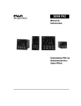
Data structure of the CNC with user interface on an IBM-PC and an SOT
(stations operator terminal).
MT-CNC Data User Interface
NC Program
List
12
1.
Parameter
Set
99
1.
99
1.
Tool List
SOT Data
Hard Disk
User
Interface
NC List
Process
1
0
NC Variable
List Process
0
1
2
2
3
3
4
4
5
6
Cur. Tool List
5
6 for Process
3
2
01
Zero Point for
Process
3
2
01
4
4
5
5
4
6
Current
Tool List for
Process
NC Event
3
2
List for
6
5
Process 0 1
4
NC Variable
3
2
List for
Process 0 1
MDI Block
Entry
6
6
MDI Block
Entry
V.24 Serial Interface
Operating at 19,000
Baud
5
0
Zero Points
for Process
1
01
2
2
3
3
4
4
5
5
6
6
V.24 Serial Interface
Operating at 19,000
Baud
MT-CNC
Memory
Parameters
System Parameters
Axis Parameter
Process Parameter
Achse 1
Process 0
Tool List
NC Events
NC Variables
NC Cycle Programs
D Corrections
Process 0
Process 0
NC Program Memory A
Zero Points
for Process
Data for
Process
0
0
1
1
2
2
3
3
4
4
5
5
Process 0
Process 0
Process 0
.
.
4
5
3
2
3 4
5
1 2
3 4
1 2 3 4 5
5
1 2
4
3
1 2 3 4 5
5
1 2 3 4
2
1
20
6
6
6
6
6
6
NC Program Memory B
6
6
Zero Points
for Process
Data for
Process
Setup List
Setup List
NC Program
NC Program
No. 1
.
No. 99
No. 1
.
No. 99
0
0
1
1
2
2
3
3
4
4
5
5
6
6
Fig. 1-1: CNC data organization
DOK-MTC200-NC**PRO*V17-ANW1-EN-P
NC Programming 17VRS
General Information 1-3
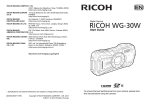
Approximately 400KB available memory is present on the basic version of
the CNC. As shown in Figure 1-1, the CNC-memory is divided into several
areas. The individual areas are described briefly in the following sections.
The CNC controller is adapted to the given machine or system by means
of parameters. Up to 99 different parameter sets can be managed on the
user interface.
The parameters are divided into the following areas:
System parameters
The system parameters define how many processes and axes need to be
managed by the CNC controller as well as what type of tool management
system is present.
Process parameters
The process-specific data, for example the default plane, programmable
and maximum displayable places to the right of the decimal point, maximum speed for contour mode, etc. are specified in the process parameters.
Axis parameters
The axis is assigned to specific processes in the axis parameters; and the
corresponding axis limit data—for example, maximum axis speed, travel
limits—are defined here.
A detailed description of the system, process and axis parameters may be
found in the System Parameter Reference Manual document.
Tools list
The tool list for a process contains the actual tool data for all tools assigned to the process, and it therefore represents an image of the magazine which is present at the station. Up to 99 different tool lists can be
managed on the user interface. The NC commands for tool handling are
described in Chapter 8 "Commands for Tool Management." A complete
description of all data and functions relating to tools is provided in the
sections on "Tool Management" and "Tool Data Management."
NC events
NC events are binary variables which can be used by the NC-program. A
detailed description of NC-events and event-dependent functions is provided in Chapter 7, "NC Events".
NC-Variable
An NC variable represents a numerical value which is capable of
changing. A total of 1792 NC-variables are available in the CNC (256 NCvariables for each process). Chapter 10, "Programming Subroutines and
Cycles," provides a detailed description of what can be accomplished with
NC-variables.
NC cycle programs
A specific memory area is available in the CNC for NC cycle programs
supplied by the machine builder and INDRAMAT GmbH. Additional information on NC cycle programs is provided in the manual on "NC Cycles."
D corrections
The D-corrections are additive relative to the tool geometry data registers.
The D-corrections act in an additive manner relative to the existing geometry registers L1, L2, L3 and R. 99 D-corrections are available for each
of the 7 processes. Each D-correction contains the L1, L2, L3 and R
registers. The assignment of values in the D-correction register can be
accomplished using the CNC operator interface or the SOT.
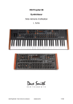
NC program package
An NC-program package contains all necessary Tool Setup Lists (tool
specifications data) and NC-programs of all processes used in the machining work. Up to 12 different NC-program packages can be managed on
the user interface. Dividing the NC-memory into two areas, A and B, permits two NC-program packages to be managed simultaneously in the
CNC. The decision as to which of the two NC-program packages is to be
run is made by the operator via the user interface or via the SPS. While
one NC-program package is already running, a second NC-program
package can be loaded into the controller's memory. This will overwrite
any NC-program package that may already be present in the controller.
DOK-MTC200-NC**PRO*V17-ANW1-EN-P
1-4 General Information
NC Programming 17VRS
NC Program Package
6
5
3
4
2
1
Data for
Process 0
Setup List (Optional)
NC Program 1
.
.
NC Program 99
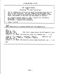
Fig. 1-2: NC program package
Tool setup list
The tool setup list contains a tool data set for each T number used in the
NC-program. This tool data set defines which tool is to be used and which
specifications this tool must meet. If the machine tool builder determines
that a setup list is not required, the T number together with its corresponding data set is used in the tool list. The setup list should be entered
before creating the program, however no later than during creation of the
program. Additional information on the setup list is provided in the manuals on "Tool Management" and "Tool Data Management."
The CNC provides up to 60 zero points (10 *(G54..G59)) for each process. The zero points are assigned to the currently active 'A' or 'B'
NC-program memory in the CNC-memory. Entries in the zero point table
on the operator interface are always assigned to the currently active
NC-program memory.
DOK-MTC200-NC**PRO*V17-ANW1-EN-P
NC Program 2-1
NC Programming 17VRS
2
NC Program
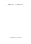
2.1
Organization of the Tool Setup Lists
A tool setup list can be created for any process which uses tool. This list
allows any given tool names or tool numbers to be assigned to the T
numbers used in the NC-program. The Setup List also contains the tool
specification data. Setup Lists can be organized to be station-specific or
program-specific.
up to 7 tool setup lists (1 per process) are possible.
Station-specific organization
up to 693 tool setup lists (7 processes * 99 tool setup lists) are possible.
Program-specific organization
NC Program Package
Process 0
NCP 1
Process 6
Process 1
NCP 1
EL
EL
NCP 1
EL
.........
NCP 99
NCP 99
NCP 99
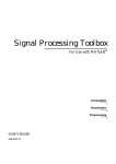
Fig. 2-1:Setup Lists with station-specific organization
NC Program Package 6
Process 0
Process 1
Process 6
NCP 1
EL 1
NCP 1
EL 1
NCP 2
.
EL 2
NCP 2
.
EL 2
NCP 99
EL 99
NCP 99
EL 99
........
NCP 1
EL 1
NCP 2
.
EL 2
NCP 99
EL 99
Fig. 2-2: Setup Lists with program-specific organization
When program-specific organization of Setup Lists is used, the size of the
program memory available to NC-programs is decreased!
Note:
The station- or program-specific Setup Lists are defined in the
system parameters.
The machine builder must declare in the SPS program
whether the CNC will work with or without Setup Lists!
The setup list should be completed when the NC-program is written, however no later than when the NC-program is transferred into the system.
This is the only way that names referencing T numbers in the NC-program can be meaningful. The final assignment of the tools located in the
tool magazine to the T numbers used in the program is made when the
program is initiated (optional Tool Check).
DOK-MTC200-NC**PRO*V17-ANW1-EN-P
2-2 NC Program
2.2
NC Programming 17VRS
Program Organization
The NC-program and its command set is based on DIN 66025 / ISO Draft
6983/2 together with specific INDRAMAT enhancements. 99 NC-program
packages can be managed on the user interface. Each NC-program
package can contain up to 99 NC-programs for each process. Thus, an
NC-program package can consist of 693 NC-programs (7 processes * 99
NC-programs).
NC Program Memory B
NC Program Memory A
NC Program 04
Advance Program
NC Cycle Memory
9
Reverse Program
Subroutines of the
Advance and Reverse
Program
Program No. 99
Program No. 0
Indramat GmbH
and Machine
Builder's
Subroutines and
Cycles
User Cycles and
Subroutines
Fig. 2-3: NC program organization
An NC-program can contain both
• the forward and
• the reverse program for an operation.
If subroutines for the reverse program are not found in the current NCprogram, a search using the number 99 is automatically performed in the
NC-program. If the subroutine for the cycle is not located in program
number 99, a search is performed in program number 0.
Program No. 99
Program number 99 is suitable for frequently used program modules such
as user cycles, the tool change subroutine, or the reverse program.
Program No. 0
Program number 0 is reserved for the INDRAMAT machining cycles and
for the machine builder's cycles. A detailed description of the INDRAMAT
machining cycles is provided in the documentation on "NC-cycles."
NC-programs are assigned to a given process.
• The NC-program assigned to process number 0 (management process) is called a part program.
• The NC-programs for processes 1 to 6 are called process programs.
From this point on they are referred to as NC-program
If a system consists of a number of processes, the part program in process 0 handles the coordination of all the other processes.
DOK-MTC200-NC**PRO*V17-ANW1-EN-P
NC Program 2-3
NC Programming 17VRS
Advance program
An advance program consists of a complete sequence of NC-blocks
needed to produce a workpiece. In addition to the path information
needed for machining, the advance program also contains all additional
auxiliary functions and branch/jump commands for subroutines and cycles.
The advance program ends with the NC-block in which RET (end of program with reset) is programmed.
Example
T4 BSR .M6
T8 MTP
G00 G90 G54 X0 Y0 Z50 S5000 M03
G01 X46 Y144 Z2
.
.
RET
Tool change SF D50
Next machining tool
Home position
Pos. at safety distance
Reverse Program
A reverse program consists of a complete series of NC-blocks which describe an operation sequence which is to be performed to establish the
reference or home position of a station, regardless of how complicated
the traverse moves required for it might be. As a rule, a reverse program
is programmed in program number 0 or number 99 so that it can be used
as a subroutine to establish the reference point or home position of a station or machine.
The reverse program begins with the NC-block in which the label .HOME
is programmed. Other entry points for the reverse program can be defined in the advance program with the aid of reverse vectors (see Chapter
9 "Commands for Controlling Processes and Programs ").
When reverse programming is done in a systematic manner without any
omissions, the operator can extract the station(s) or the machine from the
most complicated machining situations and return to the initial position in
the event of errors or malfunctions or in any given EMERGENCY STOP
situation. This is done safely and without the risk of collision.
Example
.HOME
MRF
D0
G40 G47 G53 G90
G74 Z0 F1000
G74 X0 Y0 F1000
RET
Note:
DOK-MTC200-NC**PRO*V17-ANW1-EN-P
Global Homing
Go to tool magazine reference point
Cancel D-corrections
Cancel overrides
Go to Z axis reference point
Go to X and Y axis reference point
It is not necessary to program a reverse program unless the
machine builder has specified in the process parameters that
a reverse program must be programmed.
2-4 NC Program
2.3
NC Programming 17VRS
Process-Specific Programming
The CNC is organized into a maximum of 7 processes. Each process has
its own NC-block preparation which combines the data from the NC-program with data such as zero points, Setup Lists, etc.
The number of processes is declared in the system parameters. Or if
more than 2 processes are declared, process 0 is generally used to synchronize the other processes.
Example
Use of a number of processes on a double-slide single-spindle lathe with
a milling head:
• Process 0
Synchronization of processes 1 and 2, coordinates whether the processes are working simultaneously and asynchronously or synchronously.
• Process 1
Process 1 contains the X and Z axes for the upper turret head.
• Process 2
Process 2 contains the X and Z axes for the lower turret head, the
main spindle S1, the C axis, and spindle S2 as the driven tool spindle.
Process 1
Program No. 10
X
N0000 G90 G54 G18
N0001 G00 X20 Z0
.
.
Z
N00xx M030
Process 1
Process 0
Program No. 10
N0000
N0001
N0002
N0003
N0004
.START
DP1 DP2
SP1 10
SP2 10
AP1 AP2
C
S1
Process 2
Process 2
Program No. 10
N0000 G90 G54 G18
N0001 G00 X20 Z0
.
.
Z
S2
X
N00xx M030
Fig. 2-4: Double-slide single-spindle lathe for milling work
DOK-MTC200-NC**PRO*V17-ANW1-EN-P
NC Program 2-5
NC Programming 17VRS
2.4
Elements of an NC Block
An NC-block contains data for performing an operating step. The NCblock consists of one or more words as well as the NC control commands. The NC-block length must not exceed 240 characters, and it can
be split among no more than four lines.
An NC-block is comprised of the following elements:
• NC-block number
• Branch label
• NC-words (NC control command(s))
• Message
• Remark in the program
• Remark in the source program
Structure of an NC-block
N0020
Program
control
command
G54
G01
Correction
call
Traverse
statement
Block no.
X50 Y60
F2000 S1500
Geometry
statement
Technology statement
M03
Auxiliary function
NC words (NC control commands)
All the elements of an NC-block except for function assignments must be separated by at least one space.
CAUTION
The priority for processing an NC-block in the NC-memory is as follows:
NCblock
number
Label
Aux.
function
before
motion
N1234
.ENDE M03
G codes
NC
variables
Axis
Values
G01
@100=x X100
Y100
Interpolation
parameters
F values S
value
I0
J50
F1000
Aux.
function
after
motion
S800 M03
Palette
commands
Tool
commands
Events
SEL 1
MTP T6 SE 5
Process
commands
Program
control
commands
DP 1
HLT
NC Block Numbers
Syntax
N××××
× = 0..9
Each NC-block begins with the letter N followed by a 4-digit decimal integer number as the NC-block number. The numbering of NC-blocks in an
NC-program always starts at N0000. The numbering of NC-blocks is
automatically generated by the user interface when programming in 1step intervals.
When NC-blocks are inserted via the user interface, all subsequent NCblocks are automatically renumbered.
DOK-MTC200-NC**PRO*V17-ANW1-EN-P
2-6 NC Program
NC Programming 17VRS
NC blocks that can be skipped
In an NC-controlled machine tool, a simple way must be provided to skip
NC-blocks so that certain functions such as gaging operations, part loading and unloading and the corresponding program NC-blocks can be allowed to proceed in a controlled manner or can be skipped.
Blocks in a part program which are not to be processed each time the
program is executed must be identified by a slash "/" at the beginning of
the NC-block. These NC-blocks are only processed when the user activates the skip function by pressing the Skip NC-block machine control
key.
Example
N0100 G01 X20 F400
;Additional gaging cut
N0101 / G00 X300 M03 S6500
N0102 / G01 Z45 F100
N0103 / G00 X370 M05
N0104 / HLT
In cyclical mode, the CNC skips a series of NC-blocks if the operator activates the skip function before the first NC-block in this sequence is processed. If the user presses the Skip NC-block machine control key while a
sequence of NC-blocks containing the skip marks is processing, this will
have no effect on processing in cyclical mode. The CNC continues to
process regardless of this action.
During single-block processing mode, the CNC checks whether the skip
function is active at the beginning of each NC-block. In contrast to cyclical
mode, this gives the user the opportunity to control which individual NCblocks are skipped.
The slash marks used to mark NC-blocks to be skipped,
stop lookahead NC-block processing. Thus, contour
mode is not possible with NC-blocks marked to be
skipped.
CAUTION
2.5
NC Word
The NC-word contains the DIN 66025 instructions and various specific
INDRAMAT enhanced commands.
The NC-word is divided into:
• geometric
instructions
• technology
instructions
• Traverse instructions
• Auxiliary functions
• Override calls
• Enhanced functions
Ö
Ö
Ö
Ö
Ö
Ö
Axis positions X__ Y__
Spindle speed, feed S__ F__
Rapid traverse,
circular interpolation G__ G__
Coolants, tools M__ T__
Tool overrides, zero points G__ G__
Conditional branch, calculations
A word is comprised of the address letter and the numerical value with
which specific machine moves and auxiliary functions are initiated.
Address letter
The address letter is generally a text character.
DOK-MTC200-NC**PRO*V17-ANW1-EN-P
NC Program 2-7
NC Programming 17VRS
Numerical value
The numerical value can have signs and decimal points. The sign is located between the address letter and the numerical value. A positive sign
does not need to be entered.
Word Format
Address Letter
Value
500
X
Extended Address Format
Address Letter
S
No.
Space Value
1
1000
Fig. 2-5: Word syntax
Example
; Enhanced address structure for an X1 and Y1 axis
G01 X1 50.45 Y1 35.456 F1000
Thread position 1
Z10
Z to safety distance
M103 S1 1000
1st spindle 1000 RPM
Note:
There must be a blank between the address and the numeric
value that is to be assigned.
The decimal point is fixed to achieved the resolutions shown below:
X0.00001 =
X0.0001 =
X0.001
=
0.01 µm
0.1 µm
1 µm
etc.
Leading or following zeros can be ignored in the decimal point format.
Decimal point entry is possible in the following addresses:
Address letters: I, J, K, P, S, F, contents of @xxx
Note:
The maximum number of places to the right of the decimal
point which can be programmed is set in the process parameters.
Branch Label
Syntax
.××××××
× = 0..9 , A..Z , a..z
A branch label points to a branch-to label in a destination NC-block. A
branch label is always present two times, once in the NC-block in which
the branch occurs and once in the destination NC-block to which the
branch is to be performed. A label always marks a program branch, regardless of whether the branch is conditional or unconditional.
The branch-to address (destination label) can be in the same NC-program. If the branch-to address is not found, a search is performed for the
branch-to address in program no. 99 or program no. 0.
Certain labels are reserved by their names for the
INDRAMAT canned cycles and for those of the machine
builder.
NOTE
DOK-MTC200-NC**PRO*V17-ANW1-EN-P
2-8 NC Program
NC Programming 17VRS
In terms of syntax, the label begins with a decimal point followed by at
least one and no more than six legal characters. The syntax is not case
sensitive. The * sign following the decimal point is reserved for
INDRAMAT canned cycles. When a label is programmed in a NC-block,
the label must be the first element in the NC-block after the number. A
branch command using a label is considered to be a program control
command, and, based on its priority, it is performed last.
Example
G54 G90 G00 X0 Z0
G04 F5
BSR .ENDE
RET
.ENDE
M05
G04 F1
RTS
Message
Syntax
[ Text ]
Each NC-block can contain a message which will be displayed in the
diagnostic menu (station window) in the user interface at the end of NCblock processing. The message in the diagnostics line remains active
until it is overwritten by a new message. A so-called empty message must
be programmed in order to clear the current message in the NC-diagnostics line. The message is also cleared from the NC-diagnostic line when a
program initiates. An NC-block cannot contain more than one message.
A message is written in square brackets. It must not exceed a length of
48 characters. All ASCII characters may be used. The message can be
inserted at any location in the NC-block; however, with the exception of
the comment it is always the last function to execute.
Example
N1234 G01 G54, G90 [ Traverse X to safety distance ] F1000
N1235 X500
N1236 [ Traverse Z to safety distance ] G01 G51 G90 F1000
N1237 Z100
Hint
Syntax
( Text )
Each NC-block can contain a hint. A hint is written in parentheses. It must
not exceed a length of 80 characters. All ASCII characters may be used.
The hint can be inserted at any desired location in the NC-block. The hint
is transferred to the controller memory and is shown in the current NCblock display.
An NC-block cannot contain more than one hint and one message.
Example
N1234 G00 ( Traverse X to starting position ) X150
N1235 ( Traverse Z to starting position) G01 Z10
Limitation:
Messages and hints must n o t be programmed between
individual Preparatory G-functions.
DOK-MTC200-NC**PRO*V17-ANW1-EN-P
NC Program 2-9
NC Programming 17VRS
Comment in the Source Program
Syntax
; Text
Each NC-block can contain one comment in the source program which is
introduced by a semicolon. All characters following the semicolon are
interpreted as a comment. The term comment in the source program
means that the comment is only present in the source program—that is,
on the user interface—and not in the controller memory. Compared to
messages and hints, this type offers the advantage of saving memory
space in the controller.
If a semicolon is used at the very beginning of a NC-block, the entire NCblock is marked as a comment and a NC-block number is not assigned.
Example
N0050 G01 X250 Y100 F1000
; Call centered drilling cycle
N0051 BSR .*ZENBO
Limitation:
2.6
6th drilling position
Comments in the source program must n o t be programmed between individual NC-words.
Available Addresses
Available address letters in the CNC:
A
Reserved for axis name
P
Angle
B
Reserved for axis name
Q
Auxiliary Q-function
C
Reserved for axis name
R
Radius
D
D-corrections
S
Spindle speed / position
E
Edge number
T
Tool number
F
Feed
U
Reserved for axis name
G
Preparatory G-functions
V
Reserved for axis name
H
Unassigned
W
Reserved for axis name
I
Interpolation parameter
X
Reserved for axis name
J
Interpolation parameter
Y
Reserved for axis name
K
Interpolation parameter
Z
Reserved for axis name
L
Unassigned
@
Variable
M
Auxiliary M-function
RX
Nominal radius around X
N
NC-block number
RY
Nominal radius around Y
O
Zero point database
RZ
Nominal radius around Z
An expanded address syntax is provided for the following addresses:
A(1..3)
Reserved for axis name
B(1..3)
Reserved for axis name
C(1..3)
Reserved for axis name
U(1..3)
Reserved for axis name
V(1..3)
Reserved for axis name
W(1..3)
Reserved for axis name
X(1..3)
Reserved for axis name
Y(1..3)
Reserved for axis name
Z(1..3)
Reserved for axis name
S(1..3)
Spindle speed / position
The NC syntax is not case sensitive; no distinction is made between upper and lower case. This means that "x400" can be used instead of
"X400" when programming an axis position. However, for the sake of
legibility, it is generally a good idea to write NC commands in upper case
characters.
The full ASCII character set may be used for hints and messages.
DOK-MTC200-NC**PRO*V17-ANW1-EN-P
2-10 NC Program
NC Programming 17VRS
DOK-MTC200-NC**PRO*V17-ANW1-EN-P
Motion Commands, Dimension Inputs 3-1
NC Programming 17VRS
3
Motion Commands, Dimension Inputs
3.1
Coordinate System
The coordinate system defines the location of a point or series of points in
a plane or in space relative to two or three NC axes.
As a rule, the right-hand, orthogonal Cartesian coordinate system having
axes X, Y and Z is used in NC technology. This system is defined relative
to the main axes of the machine.
Y
Y
B
R
C
Z
A
X
X
Z
Fig. 3-1: Coordinate system
All other axes are defined relative to these 3 main axes. A, B and C are
rotary or pivoting axes having X, Y or Z as their center axes.
The A axis rotates about the X axis, the B axis rotates about the Y axis,
and the C axis rotates about the Z axis. The positive direction of rotation
of rotary axes corresponds to clockwise rotation when viewed in the positive axis direction.
With milling machines, the main axes are generally named X, Y and Z.
With lathes the names are defined as Z and X.
Note:
DOK-MTC200-NC**PRO*V17-ANW1-EN-P
The axis names can be freely defined via the axis parameters.
3-2 Motion Commands, Dimension Inputs
3.2
NC Programming 17VRS
Motion Commands
The motion command or traverse instruction causes an axis to move or
traverse. The motion command consists of the address letter of the axis
address (for example, X, Y or Z) followed by the sign (+, -) to indicate the
direction of motion, and the distance to be traversed, the coordinate
value.
Syntax
Syntax:
Address Letter
Coordinate Value
Z
100.5
Address Letter
Equal Sign
X
=
Address Letter
Variable
@120
Space
Coordinate Value
X1
245.65
The coordinate value is comprised of:
• the sign,
• 6 or 5 places to the left of the decimal point,
• the decimal point
• 4 or 5 places to the right of the decimal point.
If no sign is programmed, the coordinate value is considered to be positive. If the coordinate value only has places to the left of the decimal point,
the decimal point need not be entered. Leading or following zeros can be
ignored.
If a decimal point is programmed, at least one place to the right of the
decimal point must be stated.
The number of places to the left and right of the decimal point must not
exceed 10 places.
In the notation using four places to the right of the decimal point, the
maximum value range for coordinates is:
-214748.3648
to
+214748.3647
or with five places to the right of the decimal point:
-21474.83648
to
+21474.83647
DOK-MTC200-NC**PRO*V17-ANW1-EN-P
Motion Commands, Dimension Inputs 3-3
NC Programming 17VRS
3.3
Dimension Input
The motion commands for the axes can be entered in two different ways:
• As an absolute dimension input (G90) or
• as an incremental dimension input (G91).
Input Data as Absolute Dimensions 'G90'
With absolute dimension input all dimensions are stated relative to a fixed
zero point. When the CNC-program boots, the initial setting is G90. G90
remains in effect until it is written over with G91. In the NC-program, G90
only needs to be programmed if one wishes to cancel G91.
Example
Y
100
80
[P2]
[P3]
[P1]
[P4]
60
40
20
20
40
60
80
100
120
140
X
Fig. 3-2: Absolute dimension input
G00 G90 G54 X0 Y0 Z10 S1000 M03
G01 X50 Y50 F500
BSR .DRILL
Y80
BSR .DRILL
X100
BSR .DRILL
Y50
BSR .DRILL
M05
RET
.DRILL
G01 Z-10 F300
G04 F2
Z3
RTS
DOK-MTC200-NC**PRO*V17-ANW1-EN-P
Starting position
[P1]
Branch to drilling subroutine
[P2]
Branch to drilling subroutine
[P3]
Branch to drilling subroutine
[P4]
Branch to drilling subroutine
Spindle OFF
End of program
Drilling subroutine
Drill to depth Z
Dwell time 2 seconds
Drill to safety distance
Return from subroutine
3-4 Motion Commands, Dimension Inputs
NC Programming 17VRS
Input Data as Incremental Values 'G91'
Incremental positioning defines all subsequent dimensional entries as
differences relative to the NC-block starting position.
G91 remains in effect until the end of the program or until it is overwritten
by G90.
Example
Y
100
80
[P2]
[P3]
[P1]
[P4]
60
40
20
20
40
60
80
100
120
140
X
Fig. 3-3: Input data as incremental values
G00 G90 G54 X0 Y0 Z3 S1000 M03
G01 G91 X50 Y50 F500
BSR .DRILL
Y30
BSR .DRILL
X50
BSR .DRILL
Y-30
BSR .DRILL
M05
RET
.DRILL
G01 Z-13 F300
G04 F2
Z13
RTS
Starting position
[P1]
Branch to drilling subroutine
[P2]
Branch to drilling subroutine
[P3]
Branch to drilling subroutine
[P4]
Branch to drilling subroutine
Spindle OFF
End of program
Drilling subroutine
Drill to depth Z
Delay 2 seconds
Return to safety clearance
Return of subroutine
DOK-MTC200-NC**PRO*V17-ANW1-EN-P
Motion Commands, Dimension Inputs 3-5
NC Programming 17VRS
3.4
Zero Points
Zero points and various reference points used to establish workpiece
geometry are defined on all numerically controlled machines.
Machine zero point
The machine zero point is located in a fixed position at the origin of the
machine coordinate system, and it cannot be moved.
Icon for the machine zero point
M
Machine reference point
The machine reference point is a defined point located within the working
range of the machine. It is used to establish a defined initial position after
the machine is powered on. The machine reference point is established
by the machine builder in each axis in which incremental positioning is
used.
Icon for the reference point
R
Note:
Workpiece zero point
The reference dimensions are set in the drive parameters
The workpiece zero point is the origin of the workpiece coordinate system. The programmer establishes it as the program zero point which is
used as the basis for all workpiece dimensions. The reference to the machine zero point is established by the zero offset value when the machine
is set up.
Icon for the workpiece zero
point
W
Examples
R
Y
Table
Workpiece
W
M
Fig. 3-4: Zero points—drilling/milling machine
DOK-MTC200-NC**PRO*V17-ANW1-EN-P
X
3-6 Motion Commands, Dimension Inputs
NC Programming 17VRS
X
R
M
W
Z
Fig. 3-5: Zero points—lathe (machining ahead of the center of rotation)
3.5
Zero Offsets
The zero offsets permit the origin of a coordinate axis to be offset by a
given value relative to the machine zero point. The position of the machine zero point is permanently stored in the CNC-memory and is not
changed by the zero offset.
Z
Z'
P
Z
Angle of Rotation 'P'
for the active
Plane (G18)
Y
P
X'
X
'NV' Zero
Offset
Y
X
Fig. 3-6: Zero offset
The following zero offsets are provided in the CNC:
• Programmable absolute zero offset
G50,
• Programmable incremental zero offset
G51,
• Programmable workpiece zero point
G52,
• Adjustable zero offsets
G54 to G59 and
• adjustable general offset in the zero offset table.
The coordinate zero point of each NC axis can be placed at any desired
coordinate position inside or even outside the respective traverse range
with the aid of the zero offsets, G50, G51 and G54 to G59 and the work-
DOK-MTC200-NC**PRO*V17-ANW1-EN-P
Motion Commands, Dimension Inputs 3-7
NC Programming 17VRS
piece zero point G52. This allows an identical NC-program to be processed at various machine positions.
The position of the machine zero point of each axis is declared in the
drive parameters as the difference relative to the reference point. The
value entered in the drive parameters corresponds to the coordinate value
of the reference point in the machine coordinate system.
Programmable
Workpiece Zero
Cancel Zero
Points
Point
Adjustable Zero Offsets
Enter and Change via User
O9
O8
Set Via the NC Program
G53
O9
O8
O2
O1
O0
G52
G54
O2
O1
O0
z z z z
G59
z z z
z
z
z
z
G54
to
G59
Adjustable General Offset in
the Zero Point Table
Enter Via User Interface
z
W
z
z
z
Programmable Absolute
Zero Offset
G50
Set via the NC Program
Cancel by Selecting a New
Zero Offset or by G53
Programmable
Incremental Zero Offset
G51
Set via the NC Program
Cancel by Selecting a New
Zero Offset or by G53
Total Zero Offset to Machine Zero Point
Fig. 3-7: Total of zero offsets
The total value of the zero offsets are comprised of:
the adjustable zero offsets G54 … G59 or the programmable workpiece
zero point G52 and the programmable zero offsets G50, G51 as well as
the adjustable general offset in the zero offset table.
DOK-MTC200-NC**PRO*V17-ANW1-EN-P
3-8 Motion Commands, Dimension Inputs
NC Programming 17VRS
The programmable zero offsets G50 and G51 become
inactive when G52, G53, G54 ... G59 are programmed.
CAUTION
Adjustable Zero Offsets 'G54 ... G59'
The adjustable zero offsets are entered in the zero offset table for those
axes which are present using the user interface.
The entered values function as an absolute offset relative to the machine
zero point. The calculation is performed after programming G54 …G59 in
the same NC NC-block if the respective axis is programmed. G54 ... G59
is canceled by G53 or G52.
• Depending on the setting in the process parameters, the adjustable
zero offsets G54 …G59 can be the power-on default and the initial
setting when the NC-program boots.
Example
Y
Y
100
[P5]
80
80
[P4]
[P3]
60
[P2]
40
60
20
[P1]
40
20
40
60
80 100 120
X
Enter in the Zero Offset
Table in the
User Inteface
20
with G54 :
X52.1 Y48.8
20
40
60
80
100
120
X
Fig. 3-8: Adjustable zero offset G54
G00 G90 G54 X0 Y0 Z10 S1000 M03
G01 X50 Y50 F1000
BSR .DRILL
X70 Y60
BSR .DRILL
X90 Y70
BSR .DRILL
X110 Y80
BSR .DRILL
M05
RET
.DRILL
G01 Z-10 F300
G04 F2
Z3
RTS
Starting position [P1]
[P2]
Branch to drilling subroutine
[P3]
Branch to drilling subroutine
[P4]
Branch to drilling subroutine
[P5]
Branch to drilling subroutine
Spindle OFF
End of program
Drilling subroutine
Drill to depth Z
Dwell time 2 seconds
Return to safety distance
Return of subroutine
DOK-MTC200-NC**PRO*V17-ANW1-EN-P
Motion Commands, Dimension Inputs 3-9
NC Programming 17VRS
Coordinate Plane Rotation by Angle of Rotation 'P'
Coordinate plane rotation is used to adapt the coordinate system of the
workpiece to the coordinate system of the machine. The angle of rotation
P is assigned to the individual zero offsets G54 … G59, G50, G51 and the
adjustable general offset. Coordinate rotation is always active in the active
plane (for example G17).
With the adjustable zero offsets G54 …G59 and with the adjustable general offset, the angle of rotation is entered as PHI in the zero offset table.
The angle of rotation is programmed using the address Pxxx with the
programmable zero offsets G50 and G51.
• The total of all active rotational angles is subject to the same conditions as with the zero offsets.
• As a rule, the angle of rotation is not active until the next active NC
NC-block.
• The angle of rotation is calculated in the controller as a modulo value
from 0° to 360°. This means that a programmed angle of, for example
540°, is calculated as 180°.
• Coordinate rotation cannot be programmed with the programmable
workpiece zero point G52.
Example
Y
80
[P3]
Y
X
[P2]
60
40
P1
Enter in the Zero Offset
Table in the
20
User Interface
with G54 :
X52.1 Y40 PHI 45°
20
40
60
80
100
120
X
Fig. 3-9: Adjustable zero offset G54 with coordinate rotation
G00 G90 G54 X0 Y0 Z10 S1000 M03
G01 X40 Y70 F800
BSR .DRILL
X80
BSR .DRILL
M05
RET
.DRILL
RTS
DOK-MTC200-NC**PRO*V17-ANW1-EN-P
Starting position [P1]
[P2]
Branch to drilling subroutine
[P3]
Branch to drilling subroutine
Spindle OFF
Drilling subroutine
Return of subroutine
3-10 Motion Commands, Dimension Inputs
NC Programming 17VRS
Zero Offset Tables 'O'
The CNC allows the adjustable zero offsets, G54 …G59 to be addressed
up to ten times using different coordinate values.
The zero offset table can be present up to ten times in the CNC. The
designation for each zero offset table is zero offset table.
Note:
The number of zero point databases is specified by the machine builder in the process parameters.
The selection criterion in the NC-program is the NC command O[0..9]
which, together with a single-digit number—the zero offset table number—addresses one of up to ten zero offset tables.
• The initial setting is zero offset table number 0.
• If only zero offset table number 0 is to be used, or if this number is the
first to be active in the NC-program, the number 0 will not need to be
programmed separately.
• If the zero offset table is changed in the NC-program, G53 automatically becomes active.
• Selection of a zero offset table remains modally active until the end of
the program. The zero offset table selection is reset by the commands
RET and BST.
• The NC-command O should be programmed in a separate NC NCblock. It must be activated at least on NC NC-block prior to the selection of a new zero offset.
Adjustable Zero Offsets
Entering and Changing Via User Interface
ZO Table O9
ZO Table O9
ZO Table O8
ZO Table O7
ZO Table O6
ZO Table O8
ZO Table O7
ZO Table O6
ZO Table O5
ZO Table O4
ZO Table O3
ZO Table O2
ZO Table O1
ZO Table O0
G54
ZO Table O5
ZO Table O4
ZO Table O3
ZO Table O2
ZO Table O1
ZO Table O0
G59
Switch the Zero Offest Tables to Enter and Change
the Zero Offsets Via the User Interface
Fig. 3-10: Available zero point tables
DOK-MTC200-NC**PRO*V17-ANW1-EN-P
Motion Commands, Dimension Inputs 3-11
NC Programming 17VRS
Example
Y
Y
100
80
60
80
Y
60
[P3]
[P4]
100
40
[P2]
[P5]
80
[P8]
20
60
[P7]
[P1]
40
20
40
40
60
80 100
X
ZO Pt. Table
No. 0
20
Value
G54
X17.5
Y46.5
20
[P6]
Zero Pt. Table No. 1
Entry in the ZO Table
with G54 :
20
40
60
80 100
X
120
X
X81.0 Y29.5
20
40
60
80
100
Fig. 3-11: Calling 2 zero offset tables using G54
[Zero offset table no. 0 is active]
G00 G90 G54 X0 Y0 Z10 S1000 M03
G01 X30 Y30 F1000
BSR .DRILL
Y70
BSR .DRILL
X70
BSR .DRILL
Y30
BSR .DRILL
[activate zero offset table no. 1]
O1
G00 G54 X0 Y0
G01 X40 Y40 F1000
BSR .DRILL
X60 Y60
BSR .DRILL
M05
RET
.DRILL
G01 Z-10 F300
G04 F2
Z3 F1000
RTS
DOK-MTC200-NC**PRO*V17-ANW1-EN-P
Starting position [P1]
[P2]
Branch to drilling subroutine
[P3]
Branch to drilling subroutine
[P4]
Branch to drilling subroutine
[P5]
Branch to drilling subroutine
Starting position [P6]
[P7]
Branch to drilling subroutine
[P8]
Branch to drilling subroutine
Spindle OFF
End of program
Drilling subroutine
Drill to depth Z
Dwell time 2 seconds
Return to safety distance
Return of subroutine
3-12 Motion Commands, Dimension Inputs
NC Programming 17VRS
Programmed Absolute Zero Offset 'G50' Programmed incremental zero
offset 'G51'
The programmed zero offsets G50 and G51 move the machining zero
point with
• G50 absolute or
• G51 incremental
to the most recently selected workpiece zero point by the offset values
which were declared together with the address letters.
In addition, the machining coordinate system can be moved using G50
absolute or using G51 incremental to the most recently selected workpiece coordinate system in order to rotate the active plane using the address letter P.
• The programmed zero offsets G50 and G51 are NC-block active. The
offset remains in effect until the next change of the zero offset or of the
coordinate system.
• No further functions may be programmed in a NC-block containing
G50 or G51.
Example
X
80
X
X
100
100
80
60
80
40
60
20
60
40
Z0
40
20
X2
40
60
P2
20
80 100
Z
P3
P1
P4
P5
20
G54 :
Z18.0
X15.0
P0
20
20
40
40
60
60
80
100
80
Z
100
120
Z
Fig. 3-12: Programmed zero offset G50
G00 G90 G54 X0 Z0
BSR .CONT
G50 X2
BSR .CONT
RET
.CONT
G01 X10 Z48 F750
X25 Z59
Z92 F1500
X11 Z100 F600
Z113 F1000
G00 X40
Z0
X0
RTS
[P0]
Branch to the contour subroutine
Zero offset X by 2 mm
2nd call of the contour subroutine
Contour subroutine
[P1]
[P2]
[P3]
[P4]
[P5]
Return to safety distance
[P0]
Return to main program
DOK-MTC200-NC**PRO*V17-ANW1-EN-P
Motion Commands, Dimension Inputs 3-13
NC Programming 17VRS
Programmed Workpiece Zero Point 'G52'
A workpiece zero point can be programmed as the axis position for all
axes which are present using programmed workpiece zero point G52.
When G52 is performed, the coordinate values to which the G52
command applies are assigned to the current position. This corresponds
to the definition of the workpiece zero point relative to the current position.
• Axes which are not programmed using G52 work in the machine coordinate system.
• Programming G52 produces a G53 when the change occurs. All zero
offsets which are already active are canceled.
• No further functions may be programmed in a NC-block containing
G50.
• Coordinate rotation P cannot be programmed in combination with G52.
Example
Y
80
Y
Y
100
60
100
80
80
P4
P5
60
P2
P3
40
P2
20
P3
P1
20
P4
60
40
40
P5
G52 X0 Y0
20 40
60 80 100
20
P1
X
20 40 60 80 100
NPV-Tab.
G52 X-70 Y0
X20 Y30 The entry in the zero offset table
with G52 would be: X90 Y30
20
40
60
80
100
Fig. 3-13: Call G52
G90 G53 G00 X20 Y30
G52 X0 Y0
BSR .CONT
G52 X-70 Y0
BSR .CONT
RET
.CONT
G00 X0 Y0
G01 X40 Y20 F1000
X100
Y80
X40
Y20
G00 X0 Y0
RTS
DOK-MTC200-NC**PRO*V17-ANW1-EN-P
Call G52
Branch to the subroutine
Call G52
Branch to the subroutine
Subroutine
[P1]
[P2]
[P3]
[P4]
[P5]
[P2]
Return to main program
120
X
X
3-14 Motion Commands, Dimension Inputs
NC Programming 17VRS
Cancel Zero Offsets 'G53'
All zero offsets are canceled by programming G53. This causes the
workpiece coordinate system to be switched to the machine coordinate
system.
• Depending on the setting in the process parameters, G53 can be the
power-on default and the initial setting when the NC-program starts.
• If G53 is placed in a NC-block containing G91 only the position display
is switched to the machine’s actual system.
• If the active zero offsets are canceled using G53 when tool path correction is active (G41, G42), a G40 (no tool path correction) is issued
internally. The tool correction is rebuilt for the following parameters
NC-blocks.
Adjustable General Offset in the Zero Offset Table
By having an adjustable general offset in the zero offset table, the CNC
can also offset the workpiece zero point in addition to the adjustable and
programmable zero offsets. The adjustable general offset functions in an
additive manner relative to the adjustable and programmable zero offsets.
This means that the adjustable general offset does not become active
until one of the adjustable or programmable zero offsets has been activated.
• The adjustable general offset is canceled using G53 and is not calculated in until the next time a zero offset is selected.
• An angle of rotation can be entered in the address phi in the zero offset table. This angle is added onto the already active angles of rotation.
• The adjustable general offset can never be active alone due to the
conditions described above.
Reading and Writing Zero Offset Data from the NC Program via OTD
The OTD command (Offset Table Data) can be used to read and write
the data in the zero offset table and the zero offsets which have been
activated in the NC-program from the NC-program.
Syntax
M
P
O
V
A
OTD([1/2],[0..6],[0..9],[0..9],[1..10])
Axis
Offset
ZO Table
Process
NC Memory
Please refer to the chapter „Reading and Writing ZO Data from the OTD
Program“ for a detailed description of the OTD command.
DOK-MTC200-NC**PRO*V17-ANW1-EN-P
Motion Commands, Dimension Inputs 3-15
NC Programming 17VRS
3.6
Plane Selection
Plane selection is an important requirement for correctly performing all
motion commands in an NC-program. It informs the controller of the plane
on which machining is performed in order to permit a correct calculation
of the tool correction values. It also plays a role in circle programming.
Plane Selection 'G17’, 'G18’, 'G19’
The three planes XY, ZX and YZ are formed by the coordinate axes X, Y
and Z of the three-axis coordinate system.
G17
G18
G19
Plane selection
Plane selection
Plane selection
XY
ZX
YZ
The three main axes X, Y and Z form a Cartesian coordinate system
which spans the three planes XY, ZX and YZ; the third of these axes is
always normal to the corresponding plane.
Note:
The meaning of the axes in the coordinate system is specified
by the machine builder in the axis parameters.
The preparatory commands G17, G18 or G19 are used to communicate
the desired machining plane to the NC controller, whereby the tool axis is
always normal to the machining plane. If the position of the tool axis can
be changed for design-related reasons, this also defines the machining
plane.
Ordinate
2nd Axis [Y]
G18
ZX Plane
G19
G17
YZ Plane
Abscissa
1st Axis [X]
XY Plane
3rd Axis [Z]
Fig. 3-14: Machining planes
Tool length correction
The tool length correction is always performed in the direction of the tool
axis, which means that the override is normal to the selected machining
plane.
Tool path correction
The tool path correction is always generated for the active machining
plane. Canceling the tool path correction causes the machining plane to
be changed. The tool path correction is generated for the new plane following the change.
Circular interpolations
Circular interpolation is only possible in the active machining plane. Helical interpolations superimpose linear movement in the direction of the tool
axis onto the circular interpolation taking place in the machining plane.
DOK-MTC200-NC**PRO*V17-ANW1-EN-P
3-16 Motion Commands, Dimension Inputs
Note:
NC Programming 17VRS
The default plane is specified by the machine builder in the
process parameters.
A change in the selected plane overwrites the previous plane selection
and remains modally active. The default plane is selected at the end of
the program and upon ‘Control Reset’.
Free Plane Selection 'G20'
Free plane selection permits
• the axes that span the Cartesian coordinate system to be selected,
and
• the working plane inside the spanned coordinate system and the axis
that is perpendicular to the working plane to be defined.
Linear main axes functionality
Axis def. as X Axis def. as Y Axis def. as Z
(1st linear
main axis)
(2nd linear
main axis)
G17
1st axis of
the plane
2nd axis of
the plane
G18
2nd axis of
the plane
perpendicul. 1st axis of
axis
the plane
G19
perpendicul. 1st axis of
axis
the plane
2nd axis of
the plane
G20
1st axis of
the plane
perpendicul.
axis
2nd axis of
the plane
(3rd linear
main axis)
Secondary axes functionality
Axis def. as V Axis def.as W
Axis def. as U
(1st
secondary
axis)
(2nd
secondary
axis)
(3rd
secondary
axis)
Rotary main axes functionality
Axis def. as A Axis def. as B Axis def. as C
(3rd rotary
(1st rotary
(2nd rotary
main axis)
main axis)
main axis)
perpendicul.
axis
Free Plane Selection
X axis
Y axis
Z axis
U axis
V axis
W axis
A axis
B axis
C axis
Fig. 3-15: Basic operation of the free plane selection (example: lateral cylinder
surface machining using G20 Z0 C0 X0)
Programming
Syntax
Boundary conditions
Free plane selection is performed with G20. The user can, in succession,
specify the axes that shall obtain the functionality of the 1st axis of the
working plane, of the 2nd axis of the working plane, and of the axis that is
perpendicular to the working plane.
G20 [1st axis of the plane] [2nd axis of the plane] {perpendic. axis}
[ ]:
Mandatory parameter of free plane selection
{ }:
optional parameter
• An axis (axis designation) may only occur once within a G20 command.
• Tool magazine axes and spindles are excluded.
• With G20, the user may program two or three axes.
• The working plane may be spanned by a maximum of two rotary axes.
• The third axis (that is perpendicular to the plane) must be a linear axis.
• If an NC block contains a G20 command, the only additional axis designators that may be programmed are the ones used for free plane
selection.
• The NC automatically retains the currently used axis if a specification
is not made for the axis that is perpendicular to the working plane.
• A 0 must be added to each axis designation.
DOK-MTC200-NC**PRO*V17-ANW1-EN-P
Motion Commands, Dimension Inputs 3-17
NC Programming 17VRS
• The G17 ... G20 commands form a group (G code group 2).
• A change in the plane selection overwrites the previous plane selection
and has a modal effect.
• At the end of the program (BST, RET, JMP, M02 and M30), upon a
control-reset, and upon a transition to manual mode (if the process parameter „Manual axis jogging causes reset“ has been set), the NC selects the base coordinate system (Cxx.053 axis parameter, Axis defined in tight hand coord. system as ...) and selects the working plane
that is saved there (Bxx.004 process parameter, Default interpolation
plane).
• In the axis meaning (axis functionality) axis parameters, the machine
manufacturer must (for safety reasons) allocate the necessary axis
functionality to the axes that follow the G20 command.
NC functions
• In circle programming and with active G20, the interpolation parameters I, J and K are allocated in the same way as with G17. The interpolation parameter (of the axis that is perpendicular to the working
plane) must not be used.
• The constant surface speed function is related to the axis with axis
meaning X. This fact must be taken into account during free plane selection if the axis meaning X is assigned via G20 to another axis.
• Thread cutting (G33), tapping (G63, G64 and G65) and feed per
revolution (G95) are functions of the linear primary axis. Any axis - except a rotary axis - with the axis meaning X, Y or Z may perform them.
• The NC always processes the tool and D corrections in the axes with
axis meaning X, Y or Z.
NOTE
Detailed description
DOK-MTC200-NC**PRO*V17-ANW1-EN-P
• When free plane selection is activated via G20, the
controller cancels the constant surface speed function
(G96) and activates the spindle speed in rpm function
(G97)
• Furthermore, the controller activates straight line interpolation (G01) when free plane selection is activated.
Please refer to the description „Free plane selection and lateral cylinder
surface machining“ in Folder 5 for further information about free plane
selection.
3-18 Motion Commands, Dimension Inputs
NC Programming 17VRS
Example
A turning center possesses the following axes within a process (axes
within the turning center (process 0)):
Axis designation
Axis meaning
X1
X
Turning slide
X2
W
Milling slide
Y
Y
for milling
Z
Z
for turning and milling
C
C
for machining on the lateral
surface
B
B
swivel axis for the milling
slide
U
U
tailstock
S1
S1
main spindle
S2
S2
tool spindle for milling
X1
Comment
X2
B
S2
Z
Y
U
C/S1
Fig. 3-16: Location of the axes within the turning center
Selection and axis allocation:
To perform the different machining tasks, the following planes are selected during machine operation:
G code
Linear main
axes
Secondary
axes
Rotary main
axes
Working
plane
Perp.
axis
Comment
Axis m.
X
Axis m.
Y
Axis m.
Z
Axis m.
U
Axis m.
V
Axis m.
W
Axis m.
A
Axis m.
B
Axis m.
C
G18
X1
Y
Z
U
-
X2
-
B
C
Z X1
Y
Turning
(=power-on
state)
G20 X2=0 Y0 Z0
X2
Y
Z
U
-
X1
-
B
C
X2 Y
Z
Milling
(corr. to G17
with X2)
G20 Z0 X2=0 Y0
Z
X2
Y
U
-
X1
-
B
C
Z X2
Y
Milling
(corr. to. G18
with X2)
G20 Y0 Z0 X2=0
Y
Z
X2
U
-
X1
-
B
C
YZ
X2
Milling
(corr. to G19
with X2)
G20 Z0 C0 X2=0
G32 RI=80
Z
C
X2
U
-
X1
-
B
C
CZ
X2
Lateral cylinder
surface machining
DOK-MTC200-NC**PRO*V17-ANW1-EN-P
Motion Commands, Dimension Inputs 3-19
NC Programming 17VRS
When ‘G20 Z0 C0 X2=0‘ is used for selecting the coordinate system of
the subsequent lateral cylinder surface machining process, the axis
meanings are allocated as follows (example):
• Starting from the allocations that have been defined in the axis parameters, the axis Z obtains the axis meaning X, and the axis X1 the
axis meaning Z.
• In a second step, axis C obtains axis meaning Y and axis Y obtains
axis meaning C.
• In a third step, the NC assigns the axis meaning Z to the axis X2 and
the axis meaning W to the axis X1.
3.7
Diameter and Radius Programming 'G15' / 'G16'
Workpieces which are machined on lathes generally have a circular cross
section. The CNC permits the workpiece dimensions to be entered in two
ways upon programming:
• as diameter dimensions and/or
• as radius dimensions
The names of the preparatory G-functions are as follows:
G15
Radius programming
G16
Diameter programming
Note:
The power-on default for radius and diameter programming is
set by the machine builder in the process parameters.
Diameter programming relates exclusively to the X axis.
Example
with diameter programming
X
[P4]
[P3]
50
[P2]
[P1]
40
Z
100
Fig. 3-17: Example of diameter programming
; Lathe, G16 is set as the default position through process parameters
G01 G90 X40 Z-8 F1000
[P1]
Z-30
[P2]
X50 Z-63 F500
[P3]
Z-100 F1000
[P4]
RET
The following conditions apply for diameter programming:
• With absolute positioning (G90) the programmed X value is interpreted
as a diameter; negative X values (diameters) are permitted. With circles, the center points of the circles as well as the end points are to be
specified as diameters.
• With incremental position statements (G91) the difference in diameter
relative to the previous position is stated. Beginning with the old diameter, the tool traverses the stated traverse difference to the new
DOK-MTC200-NC**PRO*V17-ANW1-EN-P
3-20 Motion Commands, Dimension Inputs
NC Programming 17VRS
position. With circles the circle center points and end points are to be
stated as a difference in diameter relative to the starting point.
• The thread lead is interpreted as a radius dimension when machining
face threads on a lathe.
• Functions like constant surface speed and feed per revolution in the X
direction are not affected by diameter programming.
• If position data are read into a NC-variable for the diameter axis, this is
the diameter value.
• The zero offsets for the X axis are programmed in radius.
• The tool corrections in the X axis are interpreted as radius values.
• The diameter symbol ∅ is used in the position display to indicate the
axis in which diameter programming is active.
3.8
Dimensional Units
Upon setup, machine tools are specified for a certain basic programming
unit (mm or inches). To produce workpieces which are dimensioned in a
different dimensioning unit on this machine, the dimensional units can be
changed for coordinate values, speed values, and programmable offsets
by using Preparatory G-functions.
Note:
The basic unit to be used in programming is specified by the
machine builder in the process parameters.
Inch Programming Input 'G70'
If millimeters is set in the process parameters as the basic programming
unit, the subsequent values are interpreted as inch data and are converted to inches internally after G70 has been programmed.
• Motion commands (coordinate values); for example X5.5 inches is
converted to X139.7 mm.
• Interpolation parameters I, J and K and radius R;
• Feed data F and G95 F; for example, F20 inch/min is internally converted to F508 mm/min;
• Programmed offsets G50, G51 and G52;
• Motion commands assigned by means of NC-variables (X=@050),
interpolation parameters (I=@051), feedrate information (F=@052)
and programmable offsets (G50 X=@053).
G70 remains in effect until the end of the program or until it is overwritten
by G71.
DOK-MTC200-NC**PRO*V17-ANW1-EN-P
Motion Commands, Dimension Inputs 3-21
NC Programming 17VRS
Metric (mm) Programming Input 'G71'
If 'inches is set in the process parameters as the basic programming unit,
the subsequent values are interpreted as millimeter data and are converted to inches internally after G71 has been programmed.
• Motion commands (coordinate values); for example X127mm is converted to X5 inches.
• Interpolation parameters I, J and K and radius R;
• Feed data F and G95 F; for example, F1500 mm/min is internally converted to F59.05 inches/min;
• Programmable offsets G50, G51 and G52;
• Motion commands assigned by means of NC-variables (X=@050),
interpolation parameters (I=@051), feedrate information (F=@052)
and programmed offsets (G50 X=@053).
G71 remains in effect until the end of the program or until it is overwritten
by G70.
Example
Ø X
[P4]
[P3]
76,2
¼ Circle 1 inch
+K
+I
[P2]
50,8
[P1]
[P0]
45
20
5
50,8
76,2
90 100
Z
Fig. 3-18: Millimeters as the basic programming unit, and change to inches G70
G00 G90 G54 X45 Z100
G01 X50,8 Z90 F800
G70
Z3 F35
G02 X3 Z2 I3 K3
G71
G01 Z5
•
RET
DOK-MTC200-NC**PRO*V17-ANW1-EN-P
[P0]
[P1]
Change to inches
[P2]
[P3]
Change to mm
[P4]
3-22 Motion Commands, Dimension Inputs
3.9
NC Programming 17VRS
Mirror Imaging of Coordinate Axes 'G72' / 'G73'
The programmable mirror function permits the mirror imaging of any desired coordinate axes within a machining program. When a coordinate
axis is mirror imaged, the original contour is machined symmetrically opposite in the same size and at the same distance on the other side of the
mirror imaging axis.
The activation and deactivation of mirror imaging preparatory G-function
is programmed using the Preparatory G-functions in the part program.
The mirror function can be activated via G73. It remains latched until it is
canceled by G72 or until it is automatically reset at the end of the program
(RET, M002/M030) or by BST. G72 sets all mirror imaging axes back to
the default position.
Syntax
Mirroring one axis
G73 <axis name>-1
G72
Mirror function ON
Cancel mirror function for all axes
The following rule applies to the mirror imaging of an axis:
• The signs of the coordinates of the mirror imaged axis are interchanged.
• In the case of circular interpolation the direction of rotation is switched.
(G02→G03, G03→G02)
• The machining direction of the path correction is reversed (G41→G42,
G42→G41)
Mirroring two axes
The following rules apply to mirror imaging two axes in a single plane:
• The signs of both mirror-imaged coordinates are interchanged (X-Y,
Z-X, Y-Z)
• In the case of circular interpolation the direction of rotation remains the
same.
• The machining direction of the path correction remains the same.
The zero offsets G54...G59, G52 and the adjustable offset are not mirror
imaged. The programmable zero offsets G50 and G51 are also mirror
imaged in programming after the mirror image function has been selected.
• The Preparatory G-functions for mirror imaging are assigned to Preparatory G-function group 18.
• Selecting mirror imaging does not result in any axis movement. The
tool path correction and NC-block lookahead are terminated when mirror imaging is selected. Tool lengths are not mirror imaged.
• When main axes are mirror imaged, the workpiece is always mirror
imaged.
• The position display shows the corresponding workpiece coordinates.
DOK-MTC200-NC**PRO*V17-ANW1-EN-P
Motion Commands, Dimension Inputs 3-23
NC Programming 17VRS
Example
Mirror Imaging
Y
70
60
50
40
4
1
30
20
10
-10
3
X
10 20 30 40 50 60 70
2
Fig. 3-19: Correlation when mirror imaging one or more coordinate axes
NC program
DOK-MTC200-NC**PRO*V17-ANW1-EN-P
G00 G54 G90 X0 Y0
BSR .TRIA
G50 X50
G73 X-1
BSR .TRIA
G72
G50 X-20 Y40
G73 X-1 Y-1
BSR .TRIA
G72
G50 X-50 Y20
G73 Y-1
BSR .TRIA
G72
RET
.TRIA
G90 G01 X30 Y30 F1000
X130
X30 Y90
Y30
G00 G54 X0 Y0
RTS
c No axis mirror imaged
fX axis is mirror imaged
e X and Y axes are mirror imaged
d Y axis is mirror imaged
Subroutine for the triangle
Triangle starting point
Endpoint = starting point
3-24 Motion Commands, Dimension Inputs
NC Programming 17VRS
3.10 Scaling 'G78' / 'G79'
The scaling function provides programmable scaling factors to change the
scale used for the distance to be traversed on all machine axes.
The activation and deactivation of the scaling preparatory G-function is
programmed using the Preparatory G-functions in the part program.
Scaling can be activated via G79. It remains modally active until it is canceled by G78 or until it is automatically reset at the end of the program
(RET,M002/M030) or by BST. G78 resets all scaled axes back to the default state.
Syntax
G79 <axis name><scaling factor>
Scaling ON
G78
Scaling OFF for all axes
The following values are recalculated for scaling:
• Axis coordinates
• Interpolation parameters
• Radius
• Programmable zero offsets G50 and G51
• Thread lead
• Effective clearances
The zero offsets G54...G59, G52 and the adjustable offset are not scaled.
The programmed zero offsets G50 and G51 are also scaled in programming after the scaling preparatory G-function has been selected.
• The Preparatory G-functions for scaling are assigned to Preparatory
G-function group 19.
• The scaling factors must always be positive values.
• For circle radius programming with R using G02/G03 or with the nominal radii RX, RY and RZ, the scaling factors used in the active machining plane must always be quantitatively identical.
• Selecting scaling does not result in any axis movement. The tool path
correction and NC-block lookahead are terminated when scaling is
selected. Tool lengths are not scaled.
• With circular interpolation an error message will be issued if the scaling factors have different absolute values. The same applies to rotary
axis programming using nominal radii.
• The numerical value which results after recalculation using the scaling
factor appears in the position display. The actual value and the distance-to-go correspond to the real axis positions.
• If the scale factor is > 1, the original component is enlarged.
• If the scale factor is < 1, the original component is reduced in size.
• In the internal calculation definition, mirror imaging is performed first
followed by scaling.
DOK-MTC200-NC**PRO*V17-ANW1-EN-P
Motion Commands, Dimension Inputs 3-25
NC Programming 17VRS
Example
Scaling
Y
70
60
50
40
1
30
20
First Traverse Move
10
after Selecting Scaling
-10
X
10 20 30 40 50 60 70 80 90 100 110 120 130 140 150
Y
80
70
60
50
40
30
20
10
2
X
10 20 30 40 50
100
Fig. 3-20: Example of programming using the scaling preparatory G-function
NC program
DOK-MTC200-NC**PRO*V17-ANW1-EN-P
G00 G54 G90 X0 Y0
BSR .TRIA
G50 X40 Y-70
G79 X0.5 Y0.5
BSR .TRIA
G78
G00 G54 G90 X0 Y0
RET
.TRIA
G90 G01 X25 Y30 F1000
X100
X25 Y70
Y30
RTS
c Triangle without scaling
Move zero point
Set the scaling factors
d Triangle with scaling
Cancel scaling
Subroutine for the triangle
Starting position
Final position = starting position
3-26 Motion Commands, Dimension Inputs
NC Programming 17VRS
3.11 Axis Homing Cycle 'G74'
The preparatory function G74 axis homing cycle allows traversing to the
reference point along one or more axes in an NC-program or via MDI NCblock entry.
Syntax
G74 <[Axis Name][CoordinateValue=0]> <Feed>
Example
G74 X0 Z0 F10000
G74 is non-modal. In the homing cycle, each programmed axis is moved
at the homing velocity that has been entered in the axis parameters.
Notes on programming G74
• G74 deactivates the tool path and tool length correction using G40,
sets the machine zero point (G53), switches to feed programming
(G94) and to absolute dimension input (G90).
• The coordinate values of the programmed axes in a G74 NC-block
must be declared to be zero.
• If a number of axes are programmed in a G74 NC-block, the axis
movement of the axes is not performed with interpolation.
• A feedrate programmed in a G74 NC-block will also remain active for
other types of interpolation.
Note:
The reference dimensions and the homing cycle traversing
speed are set by the machine builder in the drive parameters.
3.12 Traverse to Positive Stop
The function Feed to Positive stop allows one or more axes to feed to a
mechanical stop without causing a drive error. Possible applications are:
to preload an axis slide at this stop position during machining, or to use
the axis position at the stop as a reference position for further machining.
Feed to Positive Stop 'G75'
The preparatory function G75 feed to positive stop causes the axes which
are programmed together with the preparation function in the NC NCblock to traverse in the direction of the programmed coordinate value.
Syntax
G75 <[Axis Name][Coordinate Value]> <Feed>
Example
G75 X100 Z50 F500
G75 is active only for the NC-block in which it is located. The axes are
traversed in the direction of the programmed coordinate value using the
feed which is programmed in the G75 NC-block. If a mechanical resistance—for example, a mechanical stop—is detected during this distance,
the torque which is defined by the axis parameter Cxx.044 Reduced
Torque at Positive Stop is limited based on a percentage of the peak current. The command value is not increased further; the distance-to-go and
the torque preload are maintained.
DOK-MTC200-NC**PRO*V17-ANW1-EN-P
Motion Commands, Dimension Inputs 3-27
NC Programming 17VRS
Notes on feed to positive stop
• If a feed value is not programmed in the G75 NC-block, traversing is
performed at the speed entered in the axis parameter ‘Max. Feed to
Positive Stop’.
• If the programmed final axis position value is reached, the error message:
„Positive Stop not within programmed move (@-axis)”
is issued.
• If the stop yields and wanders during operation, or if the axis slide is
forced out of position by a strong opposing force, the axis position is
updated. If this causes the initial position for the NC-block not to be
reached or the final position for the NC-block to be exceeded, the error
message:
„Positive Stop not within programmed move (@-axis)”
is issued.
• The dimensional information in a G75 NC-block can be entered in absolute mode (G90) or incremental mode (G91).
• If a number of axes are programmed in a G75 NC-block, the axis
movement of the axes is not performed with interpolation.
Note:
The parameters ‘Reduced Torque at Positive Stop’ and ‘Max.
Feed to Positive Stop’ are set by the machine builder in the
axis parameters.
Example
0
100
170
Fig. 3-21: Feed to Positive stop
G00 Z100 M3 S1250
G75 Z170 F200
•
•
G76
G01 Z100 F1000
G00 Z0 M5
RET
DOK-MTC200-NC**PRO*V17-ANW1-EN-P
Z axis to starting position
Feed to positive stop
Cancel axis preload
Z axis to starting position
Z axis to reference point
3-28 Motion Commands, Dimension Inputs
NC Programming 17VRS
Cancel All Feeds to Positive Stop 'G76'
The preparatory command G76 cancel all axes at positive stop causes
the pre-loads on all pre-loaded axes to be canceled. The actual position
value is used as the position command value so that the axis positions
can be used as reference positions for further traverse moves. The distance-to-go is ignored.
Syntax
Notes on programming G76
G76
• G76 is active only for the NC-block in which it is located.
• The preparatory command G76 cannot be programmed together with
axis data. G76 cancels the axis pre-loads on all axes which are preloaded using G75 Feed to Positive stop.
• If a program is terminated by the NC command RET, by a branch with
stop BST, when the NC-program is manually reset via Control-Reset,
or if there is a power failure, all axis preloads are automatically canceled.
3.13 Reposition and NC Block Restart
The functions
• reposition and
• NC-block restart
automate traversing back to the contour following a program interruption.
After program interruptions in which the operator withdrew the tool from
the contour in manual mode—to check and replace the inserts on the
tool, for example—the reposition function allows the operator to return to
the point of interruption, and the NC-block restart function allows him to
traverse back to the starting point of the NC-block.
Both functions are available in the manual and program-driven modes. In
manual mode the controller compensates for the difference between the
target position and the actual position in the order in which the user
presses the jog keys. In the program-driven modes, the axis are traversed
to their destination positions in the order which is programmed by the machine builder in an NC subroutine.
Reposition and NC Block Restart in the Automatic Operating Modes
Operators frequently use reposition and return to NC-block in manual
mode only in order to return the axes to the vicinity of the contour. Once
the possibility of collisions occurring is eliminated, the operators change to
one of the automatic operating modes, Automatic, Semiautomatic or Execute Program in Manual Mode, and there they continue repositioning or
NC-block restart by pressing the Start key.
By changing to a programmed-controlled operating mode well enough in
advance, tool racing and tool racing marks on the workpiece can be
avoided. Following repositioning or NC-block restart, the NC resumes
program execution without performing a new NC start.
DOK-MTC200-NC**PRO*V17-ANW1-EN-P
Motion Commands, Dimension Inputs 3-29
NC Programming 17VRS
X
X
Start position
Start position
Z
Z
movement
movement
NC-block
end position
NC-block
end position
NC-block
start position
Target position =
interrupt position
Fig. 3-22: Repositioning in the program operating
modes
Target position =
NC-block start position
Interrupt position
Fig. 3-23: Repositioning in the program-controlled
operating modes
The desired function is selected by pressing the machine operating keys
Reposition or NC-block restart. Repositioning or NC-block restart is
started by pressing the Start PB”, and the NC axes are moved to the destination position in a specified order.
• The machine builder can specify the order in which the NC axes are
traversed to the contour. This order can be adapted to the given machine configuration. This is especially necessary when additional rotary
main axes are present in addition to the spindles and the linear main
axes.
• Program execution resumes without an additional NC start as soon as
the NC has reached the destination point.
Repositioning and NC Block Restart 'G77'
G77 causes the NC to traverse to the destination position for the programmed feed axes, and in the case of spindles, to restore the status
which existed prior to the interruption. With G77 the NC traverses the
existing distance-to-go between the destination position and the current
position for feed axes (axis meanings: X, Y, Z, U, V, W, A, B, C) by performing an interpolation operation similar to the G00 interpolation. It uses
the destination position in machine coordinates that was determined at
the beginning of the repositioning or NC NC-block restart operation as the
destination position for the axes.
Syntax
G77 <[AxisName][CoordinateValue=0]> <Feed>
Example
Notes on programming G77
G77 X0 Y0 Z0 F1000
• G77 is active only for the NC-block in which it is located.
• G77 S[x] 0 ([x]=1..3) causes the NC to restore the most recently active
RPM for the spindles or it causes the NC to traverse to the specified
destination position. The NC uses the positioning speed which was
previously parameterized for spindle positioning to traverse to the destination position. An additional S value is not needed for specifying the
positioning speed.
• With rotary-axis-capable main spindles (C-axis), the state upon interruption (main spindle/rotary axis mode) must be stored in the SPS.
With repositioning or NC NC-block restart, the rotary-axis capable
main spindle must be traversed to completion in the corresponding
interruption state (main spindle/rotary axis mode).
DOK-MTC200-NC**PRO*V17-ANW1-EN-P
3-30 Motion Commands, Dimension Inputs
NC Programming 17VRS
X
Starting Position
Z
Max.
Traverse Range
for
NC-block restart
Max.
Traverse Range
for
NC-block restart
NC-block
End Position
NC-block Start Position
Point of Interruption
Fig. 3-24: Repositioning and NC-block restart
DOK-MTC200-NC**PRO*V17-ANW1-EN-P
Motion Blocks 4-1
NC Programming 17VRS
4
Motion Blocks
4.1
Axes
Linear Main Axes
The linear main axes span a Cartesian coordinate system.
They are identified by means of axis names:
• 1st linear main axis (symbol: X)
• 2nd linear main axis (symbol: Y)
• 3rd linear main axis (symbol: Z)
The axis name (address of the axis as it is to be addressed in the NCprogram) is freely configurable; however, the meaning of the axis is defined by the position of the axis in the coordinate system (see Fig. 4-1). In
the CNC the axes are permanently assigned to specific processes; however, they can be switched to other processes (see chapter 11, "NC Special Functions"). An axis cannot be addressed simultaneously in more
than one process.
Circular interpolations and the tool radius path correction can only be
performed within the machining planes spanned by the linear main axes
(G17, G18, G19).
Rotary Main Axes
Rotary main axes rotate about the linear main axes.
The axis meanings:
• 1st rotary main axis (symbol: A)
• 2nd rotary main axis (symbol: B)
• 3rd rotary main axis (symbol: C)
indicate which coordinate axis the respective rotary main axis rotates
about (see Fig. 4-1). The axis name (the address of the axis) is freely
configurable; however, the axis meaning is defined by the position of the
axis in the coordinate system. With absolute positioning (G90) the traverse range is ± 360.000 degrees. With absolute positioning (G90) the
position which is programmed in an absolute statement is traversed to
over the shortest possible path. With incremental positioning (G91) the
traverse range is ±999999.9999 degrees or ±99999.99999 degrees
(depending on the parameter setting). The sign indicates the traverse direction.
DOK-MTC200-NC**PRO*V17-ANW1-EN-P
4-2 Motion Blocks
NC Programming 17VRS
Ordinate
2nd Axis [Y]
[B]
G18
Plane ZX
G19
Abscissa
G17
Plane YZ
1st Axis [X]
[A]
Plane XY
[C]
Z Coord.
3rd Axis [Z]
Fig. 4-1: Linear main axes (X, Y, Z) and rotary main axes (A, B, C) in a reference
coordinate system
Linear and Rotary Auxiliary Axes
Linear and rotary auxiliary axes can occupy any given position in space.
• 1st auxiliary axis (symbol: U)
• 2nd auxiliary axis (symbol: V)
• 3rd auxiliary axis (symbol: W)
identify this type of axis.
The axis meanings U, V and W are completely equivalent. They can be
selected for linear and rotary axes, as well as rotary-axis capable main
spindles.
Like the other axes, auxiliary axes take part in positioning operations and
interpolation moves, and like them they reach their programmed final
value simultaneously. The path feedrate (F value) specified in the NCprogram, however, does not apply to the auxiliary axes, but only to the
linear and rotary main axes if they are programmed within a NC-block.
4.2
Interpolation Conditions
Minimized Following-Error Mode 'G06'
A Minimized Following-error mode is activated for the axis moves using
the interpolation condition G06. All subsequent moves along the path are
almost completely true to the path. The NC-block transitions are not
rounded, and they are processed free of interruptions. The path velocity is
reduced to nearly zero in the vicinity of contour corners (bends in the
path). The Minimized Following-error mode is implemented by means of a
dynamic feed forward system. A following error occurs only within the 2ms limits of the interpolation clock.
• Virtually lag-free operation can only be achieved when INDRAMAT
digital drives are used. With analog drives, G06 results in reduced-following-error operation.
• After it is selected, G06 remains modal active until it is canceled by
G07 or until it is automatically reset at the end of the program or by
BST, M02, M30.
• This function permits the gain factor to be increased to the machine's
maximum mechanical load limits. A higher gain factor produces better
dynamic characteristics in the axis moves.
DOK-MTC200-NC**PRO*V17-ANW1-EN-P
Motion Blocks 4-3
NC Programming 17VRS
Examples
Circle Diameter 160 mm
Machining Speed = F8000
Gain Factor = 7
G06, G08
Oscilloscope Function
Position Values Y Axis [mm]
Position Difference:
Position Command Value
Expansion Factor:
Axis Number : 2
Axis Type: Digital Linear Axis
Axis Designation: Y
Process: Master
Axis Number : 1
Axis Type: Digital Linear Axis
Axis Designation: Z
Process: Master
Position Values X Axis [mm]
Fig. 4-2: Circular interpolation with F8000 mm/min and Minimized Following-Error
Mode
In the circle shown in Fig. 4-2 the following-error is multiplied by an expansion factor of 1693.7. Here is the part program for the circle plot (Figs.
4-2 to 4-5).
T11 BSR .M6
G00 G90 G54 G06 G08 X199 Y136 Z5
S5000 M03
G01 Z-5 F1000
G41 X199 Y141 F8000 [or. F1000]
G03 X180 Y122 I199 J122
G01 X180 Y100
G02 X180 Y100 I100 J100
G01 X180 Y77
G03 X198 Y59 I198 J77
G00 Z5
T0 BSR .M6
RET
Tool change SF D10
Starting position
Spindle ON
Lower cutter into material
Start point for circular machining
Insertion circle
Transition element
Full circle ∅160
Transition element
Withdrawal circle
Withdraw tool to safety distance
Tool change
Return to start of program
The actual contour is nearly ideal on the NC control end due to the compensated following error. A position deviation of 0.002 mm occurred only at
the transition between the squares. The position deviation at the transition
between the quadrants can be compensated for almost completely by programming in addition friction compensation (see Chapter 11, "Special
Functions, AXD Command").
DOK-MTC200-NC**PRO*V17-ANW1-EN-P
4-4 Motion Blocks
NC Programming 17VRS
Machining Speed = F8000
Gain Factor = 7
G06, G08
Oscilloscope Function
Position Value Axis Y
Following error:
Position Command Value:
Expansion Factor: 1693.7
Position Values X Axis
Circle Section
Evaluation in Quadrant Transition
Position Deviation
Fig. 4-3: Circular interpolation with Minimized Following-Error Mode, partial view
The next figure shows, by way of comparison, the same circle at a path
feedrate of F1000 mm/min.
Circle Diameter 160 mm
Oscilloscope Function
Machining Speed =
F1000 , Gain Factor = 7
G06, G08
Position Values Y Axis [mm]
Following error:
Position Command Value:
Expansion Factor:
Axis Number: 2
Axis Type: Dig. Linear Axis
Axis Name: Y
Process: Master
Axis Number: 1
Axis Type: Dig. Linear Axis
Axis Name: X
Process: Master
Position Values X Axis [mm]
Fig. 4-4: Circular interpolation with F1000 mm/min and Minimized Following-Error
Mode
The figure below shows an evaluation of the position deviation in the
quadrant transition.
DOK-MTC200-NC**PRO*V17-ANW1-EN-P
Motion Blocks 4-5
NC Programming 17VRS
Surface Speed
= F1000
mm/min
Gain Factor = 7
G06, G08
Oscilloscope Function
Position Values Y Axis [mm]
Position Difference:
Position Command Value:
Elongation Factor: 2279.2
X Axis
Section of Circle
Position Deviation
Evaluation in Quadrant Transition
Fig. 4-5: Circular interpolation with Minimized Following-Error Mode, partial view
F1000
Interpolation with Following Error 'G07'
A following-error-containing algorithm is activated for the axis moves using the interpolation condition G07. G07 is the power-on state. It is active
and latched until it is overwritten by a G06. G07 is reset automatically at
the end of the program (RET) or by the BST, M02, M30 command. NCblock transitions which are not tangential will be rounded.
Example
Diameter of Circle
160 mm
Oscilloscope Function
Surface Speed =F8000
Gain Factor = 7
G07, G08
Position Values Y Axis [mm]
Following error:
Position Command Value:
Expansion tion Factor: 527.5
Axis Number: 2
Axis Type: Dig. Linear Axis
Axis Name:Y
Process: Master
Axis Number: 1
Axis Type: Dig. Linear Axis
Axis Name:X
Process: Master
Position Values X Axis [mm]
Fig. 4-6: Circular interpolation with F8000 mm/min and G07
In the circle shown here (Fig. 4-6) the actual contour is multiplied by an expansion factor of 527.5. By contrast, the expansion factor with G06 was a
multiplier of 1693.7—more than three times the value—which explains the
variation in the position deviation. Here is the part program for the circle
plots (Figs. 4-6 to 4-9).
DOK-MTC200-NC**PRO*V17-ANW1-EN-P
4-6 Motion Blocks
NC Programming 17VRS
T11 BSR .M6
G00 G90 G54 G07 G08 X199 Y136 Z5
S5000 M03
G01 Z-5 F1000
G41 X199 Y141 F8000 [or. F1000]
G03 X180 Y122 I199 J122
G01 X180 Y100
G02 X180 Y100 I100 J100
G01 X180 Y77
G03 X198 Y59 I198 J77
G00 Z5
T0 BSR .M6
RET
Tool change SF D10
Starting position
Spindle ON
Lower cutter into material
Start point of circular machining
Insertion circle
Transition element
Full circle ∅160
Transition element
Withdrawal circle
Withdraw tool to safety
clearance
Tool change
Return to start of program
The diameter of the programmed circle becomes smaller according to the
programmed speed and the selected gain factor. The programmed contour
will be maintained with increasing accuracy as the programmed speed becomes smaller and the selected gain factor becomes larger.
Feed Rate = F8000
Gain Factor = 7
G07, G08
Oscilloscope Function
Position Values Y Axis [mm]
Position Difference:
Position Command Value:
Expansion Factor: 527.5
Position Value
Circle Section
Evaluation on the Circle
Contour
Position Difference
Fig. 4-7: Circular interpolation with G07, partial view,
The next figure shows, by way of comparison, the same circle at a path
feedrate of F1000 mm/min.
DOK-MTC200-NC**PRO*V17-ANW1-EN-P
Motion Blocks 4-7
NC Programming 17VRS
Circle Diameter 160 mm
Feedrate =F1000
Gain Factor = 7
G07 , G08
Oscilloscope Function
Position Values Y Axis [mm]
Position Difference:
Position Command Value:
Expansion Factor: 1680.9
Axis Number: 2
Axis Type: Dig. Linear Axis
Axis Name: Y
Process: Master
Axis Number: 1
Axis Type: Dig. Linear Axis
Axis Name: X
Process: Master
Position Values X Axis [mm]
Fig. 4-8: Circular interpolation with F1000 mm/min and G07
The figure below shows an evaluation of the position deviation in the rectangular transition.
Feedrate = F1000
Gain Factor = 7
G07 , G08
Oscilloscope Function
Position Values Y Axis [mm]
Position Difference:
Position Command Value:
Exansion Factor: 1680.9
Position Values X Axis [mm]
Circle Section
Evaluation in
Quadrant Transition
Position Diffence
Fig. 4-9: Circular interpolation with G07, partial view with F1000 mm/min
Contouring Mode (Acceleration) 'G08'
The interpolation function G08 is used to adjust the final velocity at the
end of the NC-block to ensure that the transition to the next NC-block
occurs at the highest possible velocity. The crucial factor is the maximum
velocity jump which is defined in the axis parameters. In the case of a
tangential NC-block transition with the same contour velocity, the transition is made at the same velocity. The result is that workpiece surfaces
are more uniform; no free-cutting marks are produced.
• With a tangential transition and with G06 active, for example in a transition from a straight line to a small circle, the velocity is reduced to the
calculated starting velocity of the next NC-block.
• When G08 contouring mode (acceleration), G61 exact stop before
NC-block transition is programmed, G09 contouring mode (decele-
DOK-MTC200-NC**PRO*V17-ANW1-EN-P
4-8 Motion Blocks
NC Programming 17VRS
•
•
•
•
ration) is activated automatically. G08 cannot be programmed again
until G61 has been canceled.
The G08 function is active with feedrate overrides of 1%–100%. If the
feedrate override is set for more than 100%, the velocity is reduced to
100% in the NC-block transitions.
The M-functions stop NC-block execution until an acknowledgment is
received; thus, G08 does not work in NC-blocks in which an M-function is programmed.
After it has been selected, G08 remains active modally until it is canceled by G09 or until it is automatically reset at the end of the program
or by BST, M02, M30.
Interposed NC-blocks in which no interpolation moves occur do not
cause a velocity change. For example: Interposing a NC-block containing G01 F7000 would cause a speed change.
Note:
The Maximum Feedrate Change w/o Ramp is specified by the
machine builder in the axis parameter Cxx.017.
Examples
The velocity diagram (Fig. 4-10) clearly shows how the NC-block transition from the first to the second area is traversed at unreduced velocity.
The NC-block transition cannot be detected. In the NC-block transition to
the third section, the feedrate is reduced to F7000. The velocity is reduced in an optimal manner to the NC-block starting velocity without
overshooting.
3 Straight Lines X200 --> X0
Oscilloscope Function
G06 and G08
Axis Number: 1
Axis Type: Dig. Linear Axis
Axis Name: X
Process: Master with 4 Axes
-8.0000
Summed Signal Generation
Actual Position
Position Deviation
Feedrate
Change between
2nd Section and
3rd Section from
F8000 to F7000
Feedrate
Fig. 4-10: NC-block transition with G08 and F8000
Example of a program for the velocity diagrams shown in Figs. 4-10 and 411:
G54 G90 G00 G06 G08 X200
G01 F8000
X150
X50
X0 F7000
RET
Starting point of the X axis
Feedrate
1st area
2nd area
3rd area with new F-value
Return to program beginning
In the following velocity diagram (Fig. 4-11), the change in velocity between
the second area with F8000 and the third area with F7000 has been magnified using a zoom function. Here one can clearly see the contouring mode
(acceleration) occurring between the two areas.
DOK-MTC200-NC**PRO*V17-ANW1-EN-P
Motion Blocks 4-9
NC Programming 17VRS
Block Transition from F8000 to
Oscilloscope Function
F7000
G06 and G08
Axis Number: 1
Axis Type: Dig. Linear Axis
Axis Name: X
Process: Master with 4 Axes
Summed Signal Generation
Feedrate
Change Between
the 2nd Section and
the Third Section from
F8000 to F7000
Actual Position
Position Difference
Feed
Fig. 4-11: NC-block transition via G08 from F8000 to F7000
Contouring Mode (Deceleration) 'G09'
The interpolation condition G09 is used to adjust the end-of-block velocity
in such a way that as stop could be performed using the maximum velocity change without ramp defined in the axis parameters.
• Position deviations can be reduced at NC-block transitions by using
the interpolation condition G09.
• Machining using G09 requires more time, and the surface quality can
be adversely affected by the free cutting marks.
• G09 is the power-on default. It is active and latched until it is overwritten by a G08. G09 is reset automatically at the end of the program
(RET) or by the BST, M02, M30 command.
Note:
The Maximum Feedrate Change w/o Ramp is specified by the
machine builder in the axis parameter Cxx.017.
Examples
3 Straight Lines
from X200 --> X0
G06 and G09
Oscilloscope Function
Axis Number: 1
Axis Type: Dig. Linear Axis
Axis Name: X
Process: Master with 4 Axes
-8.0000
Summed Signal Generation
Actual Position
Position Difference
Feed
Fig. 4-12: NC-block transitions with G09 and F8000
DOK-MTC200-NC**PRO*V17-ANW1-EN-P
Feedrate Change
F8000 to F7000 Between
2nd Section and
3rd Section
4-10 Motion Blocks
NC Programming 17VRS
The velocity diagram (Fig. 4-12) clearly shows how the velocity of the axis
is reduced to almost 0 between the workpiece areas. The remaining velocity at which the transition to the next NC-block occurs is derived from
the axis parameter Cxx.017 Maximum Feedrate Change w/o Ramp.
Example of a program for the velocity diagrams shown in Figs. 4-12 and 4-13:
G54 G90 G00 G06 G09 X200
G01 F8000
X150
X50
X0 F7000
RET
Starting point of the X axis
Feedrate
1st area
2nd area
3rd area with new F-value
Return to program beginning
In the following velocity diagram (Fig. 4-13), the change in velocity between
the second area with F8000 and the third area with F7000 has been magnified using a zoom function.
Block Transition from F8000 to
Oscilloscope Function
F7000
G06 and G09
Axis Number: 1
Axis Type: Dig. Linear Axis
Axis Name: X
Process: Master with 4 Axes
-8.0000
Summed Signal Generation
Actual Position
Position Difference
Feedrate change
from F8000 to F7000
Between
the Second Section
and the Third
Section
Feed
Fig. 4-13: NC-block transition via G09 from F8000 to F7000
Exact Stop Before NC-block Transition (with Lag Finishing) 'G61'
The programmed destination position is traversed to within a preset exact-stop limit with the interpolation condition G61. The exact-stop limit is
defined in the axis parameters by a positioning window. When the positioning window is reached, processing switches to the next NC-block and
the next axis move starts.
• G61 exact stop before NC-block transition (with lag finishing) is automatically activated when G00, linear interpolation at rapid traverse, is
programmed.
• If G61 is programmed, the interpolation condition G08 is reset. G08
cannot be reactivated until G61 has been canceled.
• It is recommended that G61 be selected for machining sharp contour
corners and not for tangential transitions.
• After it has been selected, G61 remains modally active until it is canceled by G62 or until it is automatically reset at the end of the program
or by BST, M02, M30.
Note:
The positioning window is specified by the machine builder in
the axis parameter Cxx.023 In-Position Windows.
DOK-MTC200-NC**PRO*V17-ANW1-EN-P
Motion Blocks 4-11
NC Programming 17VRS
Examples
Test Contour: Transition from Straight Line -> Circle Not Tangential , Circle Circle Tangential
Oscilloscope Function
Position Values Y Axis [mm]
Position Difference:
Position Command Value:
Expansion Factor: 613.8
Feed:
F4000
G06 , G61
Gain = 7
Position Values X Axis [mm]
Position Difference
Transition St. Line -> Circle Transition Circle -> Circle
Not Tangential
Tangential
in Transition
St. Line -> Circle
Fig. 4-14: Contour diagram with G61
The contour diagram shown here (Fig. 4-14) illustrates how the contour is
accurately maintained by G61 in the transition from the straight line → to
the circle and from the circle → to the circle. The positioning window for
the examples shown here is specified as 0.010 mm in the axis parameters. The position deviation in the non-tangential transition from the
straight line → circle is 0.00249 mm. If the positioning window in the axis
parameters were increased in size, the transition would be made with
correspondingly higher accuracy. The position deviation is less than 0.001
mm in the tangential transition circle → circle.
Example of a program for the diagrams shown in Figs. 4-14 and 4-15:
G00 G54 G90 G06 G08 X-100 Y-100
Starting point
G01 G61 X-50 Y-50 F4000
1st straight line
G02 X50 Y-50 I0 J-50
1st semicircle
G03 X100 Y-50 I75 J-50
2nd semicircle
RET
Return to program beginning
The following velocity diagram (Fig. 4-15) shows how the velocity is reduced until the positioning window is reached. When the positioning window is reached, processing switches to the next NC-block and the next
axis move starts.
Diagram: Transition from Straight Line -> Circle Not Tangential , Circle ->
Circle Tangential
Axis Number:
4.0000
Axis Name :
Axis Number :
Axis Name :
Feed
Summed Signal Generation
Feedrate F4000
G06 , G61
Actual Position
Gain = 7
Actual Position
Transition St. Line -> Circle
Not Tangential
Fig. 4-15: Velocity diagram with G61
DOK-MTC200-NC**PRO*V17-ANW1-EN-P
Transition Circle -> Circle
Tangential
4-12 Motion Blocks
NC Programming 17VRS
Block Transition with Lag Present 'G62'
With interpolation condition G62 processing switches to the next NCblock as soon as the command values for all axes programmed in the
NC-block that are issued by the interpolator have reached their programmed final values. The system does not wait until the actual values
have reached their final position. Any lag (following error) which may be
present is not reduced as the final position is approached.
• G62 NC-block transition with lag present is suppressed when G00
linear interpolation at rapid traverse is programmed.
• Sudden contour changes and non-tangential transitions are rounded
off by programming G62.
• G62 is the power-on default. It is active and latched until it is overwritten by a G61. G62 is reset automatically at the end of the program
(RET) or by the BST, M02, M30 command.
• Machining time is reduced when G62 and G08 are programmed.
Examples
Test Contour : Transition Circle -> Circle Not Tangential , Circle ->
Tangential
Position Values Y Axis [mm]
Oscilloscope Function
Position Difference:
Position Command Value:
Expansion Factor: 2444.6
Feedrate:
F4000
G06 , G62
Gain = 7
Position Values X Axis [mm]
Position Difference
Transition St. Line -> Circle
Not Tangential
Transition Circle -> Circle
Tangential
in Transition
St. Line -> Circle
Fig. 4-16: Contour diagram with G62
The contour diagram shown here (Fig. 4-16) illustrates how the non-tangential transitions (straight line → circle) are slurred as a consequence of
G62. The contour is traversed at optimal velocity (via G08). At the contour
itself, the machining quality is identical to that achieved with G61. When
one compares the contour diagrams in Figs. 4-14 (G61) and 4-16 (G62),
one sees that the expansion factor for the position deviation is four times
as high in Fig. 4-16.
Example of a program for the diagrams shown in Figs. 4-16 and 4-17:
G00 G54 G90 G06 G08 X-100 Y-100
Starting point
G01 G62 X-50 Y-50 F4000
1st straight line
G02 X50 Y-50 I0 J-50
1st semicircle
G03 X100 Y-50 I75 J-50
2nd semicircle
RET
Return to program beginning
In the following velocity diagram (Fig. 4-17), one can see how the path
velocity in the non-tangential transition straight line → circle is reduced by
the change of direction. The tangential transition circle → circle is traversed at a constant path velocity as a consequence of conditions G62 and
G08.
DOK-MTC200-NC**PRO*V17-ANW1-EN-P
Motion Blocks 4-13
NC Programming 17VRS
Diagram : Transition Straight Line -> Circle Not Tangential , Circle -> Circle Tangential
Oscilloscope Function
4.0000
Axis Number: 1
Axis Name: X
Axis Number: 2
Axis Name: Y
Feed
Summed Signal Generation
Feedrate F4000
Actual Position
G06 , G62
Gain = 7
Actual Position
Transition St. Line -> Circle
Not Tangential
Transition Circle -> Circle
Tangential
Fig. 4-17: Velocity diagram with G62
Acceleration 'ACC'
An acceleration limit can be programmed in an NC-program using the
function ACC: programmable acceleration. This function is used, for example, to reposition the workpiece holder axes according to the weight of
the workpiece. The programmable acceleration limits the maximum path
acceleration specified in the parameters. The acceleration therefore is
programmed as a percentage of the path acceleration defined in the parameters; it is applied to all axes programmed in the NC-block.
• The value range for the acceleration therefore is from 1% to 100%.
• An acceleration factor which is outside the value range will produce an
error message when the program is executed.
• The acceleration factor can be programmed as a constant as well as a
mathematical expression. If the acceleration factor is declared as a constant, it is not possible to program places to the right of the decimal
point. If it is declared as a mathematical expression, the value is automatically rounded to an integer.
• An acceleration factor programmed using the ACC command remains
modally active until it is overwritten by a new programmed value or is
automatically reset to 100% at the end of the program or by the command BST, M02, M30.
• If the maximum path acceleration parameter was set to a very high
value which is disproportionate to the maximum possible path acceleration, the ACC command may not take effect.
Note:
The maximum Path Acceleration is specified by the machine
builder in the process parameter Bxx.007.
Example
Syntax
DOK-MTC200-NC**PRO*V17-ANW1-EN-P
G01 ACC 50 X100
G01 ACC=@10 X100
G01 ACC=10*@10+30 X100
ACC as constant
ACC as variable
ACC as math. expression
4-14 Motion Blocks
NC-program
NC Programming 17VRS
G00 G54 G90 G61 G06 X200
G01 X150 F8000
ACC 40 X50
ACC 15 X-50
RET
Starting point
1st straight line
2nd straight line acceleration factor 40%
3rd straight line acceleration factor 15%
Return to program beginning
The process parameter for maximum acceleration was set to 500
mm/sec^2 for the velocity diagram shown here. Thus, the acceleration for
the NC-block containing ACC 40 X50 was 200 mm/sec^2, and that for the
NC-block containing ACC 15 X-50 was 75 mm/sec^2.
Speed Diagram : 3 Straight Lines in X with Various Acceleration
Oscilloscope Function
Axis Number: 1
Axis Type: Dig. Linear Axis
Axis Name: X
Process: Master with 4 Axes
100%
50mm
ACC 40
100mm
ACC 15
100mm
Summed Signal Generation
Actual Position
Position Difference
Feed
Fig. 4-18: Acceleration diagram for programmable acceleration
4.3
Interpolation Functions
Linear Interpolation, Rapid Traverse, 'G00'
The coordinate values programmed using the preparatory code G00 are
traversed to at maximum path velocity. If G00 applies to more than one
axis, the traverse move is performed with interpolation.
A feedrate can be programmed with G00 using an F-word. If a feedrate (F
value) is not programmed in the NC-block, the motion occurs at the
maximum path velocity entered in the process parameter (Bxx.007). The
path velocity is limited to the maximum axis velocity entered in the axis
parameters, so that linear interpolation is always performed. The F-value
programmed with G00 remains active for all subsequent traverse moves
and interpolation types until it is overwritten by a new F-value.
Block transition with lag present (G62) is suppressed in combination with
G00. The transition to the next NC-block does not occur until all the programmed axes lie within the position window for the programmed coordinate value which is specified in the axis parameters.
If contouring mode (acceleration) is active (G08), a change to contouring
mode (acceleration) (G09) is already made in the previous NC-block. If
G00 is overwritten by a different type of interpolation, G08 is automatically
activated.
G00 remains modally active until it is overwritten by a different preparatory
code in the same G group (G01, G02, G03).
DOK-MTC200-NC**PRO*V17-ANW1-EN-P
Motion Blocks 4-15
NC Programming 17VRS
Example
G00 G54 G90 X40 Y40
X120 Y60 F8000
[P1] rapid traverse at maximum path velocity
[P2] rapid traverse with F-word
Y
60
P2
40
P1
20
20
40
60
80
100
120
X
140
Fig. 4-19: Linear interpolation, rapid traverse G00
Linear Interpolation, Feedrate 'G01'
The axes programmed using the preparatory code G01 are traversed to
their programmed coordinate value on a straight line relative to the current coordinate system using the current feedrate. The programmed axes
are started simultaneously, and they all reach their programmed end point
at the same time.
If a new feedrate (F value) is programmed using preparatory code G01,
the most recently active F-value is overwritten. The programmed F-value
functions as a path feedrate. Thus, when a number of axes are being
traversed, the velocity component of each individual axis is less than the
programmed path feedrate. If a F-word was not yet active when the controller was powered on, G01 must be used to program an F-value.
G01 remains modally active until it is overwritten by a different preparatory
code in the same G group (G00, G02, G03).
Example
Linear interpolation in 2 axes
X
Y
[P4]
100
80
100
[P4]
[P3]
80
[P2]
60
60
40
40
20
[P1]
[P1]
20
40
60
80
100
X
Z
10
Fig. 4-20: Linear interpolation, feedrate G01 with 2 axes
DOK-MTC200-NC**PRO*V17-ANW1-EN-P
0
20
-10
4-16 Motion Blocks
NC Programming 17VRS
G00 G90 G54 G06 G08
X0 Y0 Z10 S3000 M03
G01 X26.26 Y18 Z5 F2000
Z-5
Y80 F1200
X41 Y93.5
X111
G00 Z10 M05
RET
Example
Motion commands, interpolation conditions
Starting position, spindle ON
[P1] start machining position
Infeed Z axis
[P2] linear interpolation, 1 axis
[P3] linear interpolation, 2 axes
[P4] linear interpolation, 1 axis
Z axis to safety distance
Linear interpolation in 3 axes
X
Y
[P3]
100
[P2]
[P3]
80
100
80
[P2]
60
60
[P1]
40
40
[P1]
20
20
40
20
60
80
100
X
Z
10
0
-10
Fig. 4-21: Linear interpolation, feedrate G01 with 3 axes
G00 G90 G54 G06 G08
X0 Y0 Z10 S3000 M03
G01 X40 Y25.5 Z5 F2000
Z-5
X95.74 Y80 Z-10 F1200
X100 Y100 Z10 F2000
M05
G00 X0 Y0
RET
Motion commands, interpolation conditions
Starting position, spindle ON
[P1] start machining position
Infeed Z axis
[P2] linear interpolation, 3 axes
[P3] Z axis to safety distance
Spindle OFF
Return to starting point
Return to program begin
Circular Interpolation 'G02' / 'G03'
The tool programmed with G02 or G03 is moved along a circular path to
the programmed end point using the effective or programmed feedrate
(F-value). The programmed axes are started simultaneously, and they all
reach their programmed end point at the same time.
The circular motion in the direction of the programmed end point is produced:
• in the clockwise direction with G02 and
• in the counter-clockwise direction with G03 (see Fig. 4-22).
The tool is moved about the programmed center point of the circle.
A circular motion can be performed in each plane when the corresponding
G-codes are selected (G17, G18, G19). The programmed center of the
circle and the end points must lie on the same machining plane as the
starting point.
DOK-MTC200-NC**PRO*V17-ANW1-EN-P
Motion Blocks 4-17
NC Programming 17VRS
Ordinate
2nd Axis[Y]
ZX Plane
G03
G02
G18
G02
G03
G03
G19
G17
G02
XYPlane
Abscissa
1st Axis [X]
YZ Plane
3rd Axis [Z]
Fig. 4-22: Circular programming according to planes
The radius and the starting angle of the arc is calculated from the starting
point and the center point. Any radius which is determined based on the
end point and the center point and is different is ignored. This means that
the end point can only be used to calculate the final angle. Thus, the programmed end point may not always lie on the arc. The programmed end
point can therefore differ from the traversed end point.
With incremental data input (G91), the center point and the end point are
expressed relative to the starting point; with absolute input (G90), they are
expressed relative to the current zero point.
When programming uses absolute data input, the value of the starting
point is assigned to the coordinate value of a not programmed address
letter (X, Y, Z, I, J, K); with incremental input, the value 0 is assigned.
If a full circle is programmed, only the center point needs to be entered
since the starting points and end points are identical with a full circle.
The circle or arc is defined by the programmed axis commands and the
interpolation parameters. The starting point of the circle is defined by the
previous NC-block. The end point of the circle is defined by the axis value
data X, Y and Z in the G02/G03 NC-block. The center point of the circle is
defined by entered the interpolation parameters I, J and K or directly via
radius R.
Interpolation parameters I, J, K
Interpolation parameters are assigned to the axes which are used in a
circular interpolation. These parameters are parallel to the axes, and their
signs depend on the direction in which they are oriented relative to the
center point of the circle. Based on DIN 66 025, the interpolation parameters I, J and K are assigned to axes X, Y and Z.
If coordinate values are not programmed using addresses I, J and K, the
corresponding starting point is assigned with absolute dimension programming. With incremental dimension programming, the default value is 0.
With G91 programming, the interpolation parameters define the distance
from the starting point of the circle to the center point; with G90 programming they define the distance from the current zero point to the center
point.
DOK-MTC200-NC**PRO*V17-ANW1-EN-P
4-18 Motion Blocks
NC Programming 17VRS
Y
Starting Point
Center Point
End Point
+I (G90)
-J (G91)
-I (G91)
+J (G90)
X
Fig. 4-23: Circular interpolation with interpolation parameters
Example
Full circle in the X-Y plane with G90
Y
100
80
I=60
60
CP
40
[P1]
J=60
20
20
40
60
80
100
120
140
X
Fig. 4-24: Full circle with G90
G00 G90 G54 G06 G08
X0 Y0 Z10 S3000 M03
G01 X40 Y37.24 F2000
Z-10 F500
G02 X40 Y37.24 I60 J60
Alternatively: G02 I60 J60
G00 Z10
M05
X0 Y0
RET
Motion commands, interpolation conditions
Starting position, spindle ON
Starting point of circle
Infeed the Z axis
Full circle in clockwise direction
With full circle, without circle end point
Z axis to safety distance
Spindle OFF
Return to starting point
Return to program beginning
DOK-MTC200-NC**PRO*V17-ANW1-EN-P
Motion Blocks 4-19
NC Programming 17VRS
Example
Full circle in the X-Y plane with G91
Y
I=20
100
80
60
CP
J=22.76
40
[P1]
20
20
40
60
80
100
120
140
X
Fig. 4-25: Full circle with G91
G00 G90 G54 G06 G08
X0 Y0 Z10 S3000 M03
G91 G01 X40 Y37.24 F2000
Z-20 F500
G02 X0 Y0 I20 J22.76
Alternatively: G02 I20 J22.76
G00 G90 Z10
M05
X0 Y0
RET
Example
Motion commands, interpolation conditions
Starting position, spindle ON
Circle starting point with incr. data input
Infeed the Z axis
Full circle in clockwise direction
With full circle, without circle end point
Z axis to safety distance (G90)
Spindle OFF
Return to starting point
Return to program beginning
Machining on lathe in Z-Y plane
Ø X
100
80
[P5]
[P4]
+K
60
CP
+I
[P3]
40
[P2]
[P1]
20
20
40
60
80
100
120
140
Fig. 4-26: Circle programming on lathe, behind center of rotation
DOK-MTC200-NC**PRO*V17-ANW1-EN-P
Z
4-20 Motion Blocks
NC Programming 17VRS
Example of Programming Using Absolute Dimension Input (G90)
G00 G90 G54 G06 G08
Motion commands, interpolation conditions
M03 S2000
Spindle ON
X34.5 Z136.5
[P1] Starting position
G01 X40 Z128.5 F500
[P2] linear interpolation
Z100
[P3] circle starting point
G02 X80 Z60 I80 K100
[P4] quarter circle in clockwise direction
G01 Z10
[P5] machining end point
G00 X100
X axis to safety distance
M05
Spindle OFF
RET
Return to program beginning
Example of Programming Using Incremental Dimension Input (G91)
G00 G90 G54 G06 G08
Motion commands, interpolation conditions
M03 S2000
Spindle ON
X34.5 Z136.5
[P1] Starting position
G01 G91 X5.5 Z-8 F500
[P2] linear interpolation
Z-28.5
[P3] circle starting point
G02 X40 Z-40 I40 K0
[P4] quarter circle in clockwise direction
G01 Z-50
[P5] machining end point
G90 G00 X100
X axis to safety distance
M05
Spindle OFF
RET
Return to program beginning
Circle Radius Programming
In order to allow dimensions to be taken directly off workpiece drawings,
an option is provided for circular paths to be declared directly in the NCprogram by stating the radius.
A distinct circular path is only produced within a semicircle (180°) when
G02 or G03 programming is used ( see Fig. 4-27). For this reason, it is
important to indicate whether the traversing angle will be greater or less
than 180°. For arcs whose angle exceeds 180°, the radius must be entered preceded by a minus sign.
Syntax for circle radius
programming in the G17 plane
R+ ... with a traverse angle to 180°
G02
G03
X ... Y ...
R- ... with a traverse angle > 180°
Example
Defining the arc
Ø X
100
R= -30
80
[S]
[E]
60
R= +30
40
20
20
40
60
80
100
120
140
Z
Fig. 4-27: Circle radius programming, determining the sign to be used for the
radius
G01 X... Z...
G02 X... Z... R±30
DOK-MTC200-NC**PRO*V17-ANW1-EN-P
Motion Blocks 4-21
NC Programming 17VRS
As can be seen from the above example, two possibilities would result for
this programmed circle. Selecting the sign (R+30 or R-30) determines
which circle is traversed.
• The direction of motion relative to the circle end point is determined by
G02 or G03.
• Circle radius programming is not permissible with a traverse angle of
0° or 360°. The axes will remain at their starting points.
• If the circle end point is missing, the axis will remain at their starting
points. No traversing takes place.
• The programmed radius is active in the current machining plane (G17,
G18, G19).
Example
Circle radius programming in the Z-X plane
Ø X
100
[P5]
[P4]
Center Point
80
R
60
[P3]
40
[P2]
[P1]
20
20
40
60
80
100
120 140
Z
Fig. 4-28: Circle radius programming on lathe, behind center of rotation
NC program
G00 G90 G54 G06 G08
M03 S2000
X34.5 Z136.5
G01 X40 Z128.5 F500
Z100
G02 X80 Z60 R40
G01 Z10
G00 X100
M05
RET
DOK-MTC200-NC**PRO*V17-ANW1-EN-P
Motion commands, interpolation conditions
Spindle ON
[P1] Starting position
[P2] linear interpolation
[P3] circle starting point
[P4] quarter circle in clockwise direction
[P5] machining end point
X axis to safety distance
Spindle OFF
Return to program beginning
4-22 Motion Blocks
NC Programming 17VRS
Helical Interpolation
Helical interpolation is a combination of circular and linear interpolation
which is used to produce a spiraling tool path. The circular interpolation
takes place in the selected plane (G17, G18, G19) while linear interpolation is simultaneously occurring in a third axis which is perpendicular to
the plane of circular interpolation.
Z
-50
25
50
Y
50
X
Fig. 4-29: Helical interpolation
With helical interpolation an arc and a straight line erected perpendicular
to the end point of the arc are both programmed in the same NC-block.
The axis feeds are coordinated in such a way that the tool describes a
helix which has a constant pitch.
No more than one coil (corresponding to a full circle) can be programmed
in an NC-block. A number of coils in sequence can only be produced by
programming a corresponding number of individual coils.
The programmed feedrate (F-value) relates to the actual tool path.
All other conditions are the same as in circular interpolation.
Example
Helical interpolation in the X-Y plane with G90
X
Y
100
100
[P4]
80
80
60
60
[P1]
40
40
KM
I=62.5
[P2]
20
[P1]
[P3]
20
J=30
[P4]
20
40
60
80
100
X
Z
10
0
-10
Fig. 4-30: Helical interpolation with G90
DOK-MTC200-NC**PRO*V17-ANW1-EN-P
Motion Blocks 4-23
NC Programming 17VRS
Example of Programming Using Absolute Dimension Input (G90)
G00 G90 G54 G06 G08
X0 Y0 Z10 S5000 M03
G01 X40 Y20 Z5 F2000
Z-2.5
X40 Y30
G02 X85 Y30 I62.5 J30 Z-5
G01 X85 Y10
G00 Z5
M05
X0 Y0 Z10
RET
Example
Motion commands, interpolation conditions
Starting position, spindle ON
[P1] Z axis to safety distance
Z axis to machining depth
[P2] starting point of half coil
[P3] helix in clockwise direction
[P4] traverse X and Y until clear
Z axis to safety distance
Spindle OFF
Return to starting position
Return to program beginning
Helical interpolation in the X-Y plane with G91
X
Y
I=22.5
100
100
[P4]
80
80
60
60
[P1]
40
40
CP
[P2]
20
J=0
[P3]
20
[P1]
[P4]
20
40
60
80
100
X
Z
10
0
-10
Fig. 4-31: Helical interpolation with G91
Example of Programming Using Absolute Dimension Input (G91)
G00 G90 G54 G06 G08
X0 Y0 Z10 S5000 M03
G91 G01 X40 Y20 Z-5 F2000
Z-7.5
Y10
G02 X45 I22.5 J0 Z-2.5
G01 Y-20
G00 Z10
M05
X-85 Y-10 Z5
RET
DOK-MTC200-NC**PRO*V17-ANW1-EN-P
Motion commands, interpol. conditions
Starting position, spindle ON
[P1] Z axis to safety distance
Z axis to machining depth
[P2] starting point of half coil
[P3] helix in clockwise direction
[P4] traverse X and Y until clear
Z axis to safety distance
Spindle OFF
Return to starting position
Return to program beginning
4-24 Motion Blocks
NC Programming 17VRS
Thread Cutting 'G33'
The G33 function thread cutting can be used to cut
• single or multiple point longitudinal threads,
• face threads and
• taper threads with a constant lead.
Lead
1 Thread
Longitudinal Thread
Fig. 4-32: Longitudinal threads
Syntax
G33 <end point [X,Y,Z]> <lead [I,J,K]> <starting angle [P]>
The thread length is the difference between the starting point and the end
point that is programmed in the G33 NC-block. The thread entry length
and exit length in which the feedrate will be accelerated or reduced must
be taken into account. The coordinate values can be programmed using
absolute (G90) or incremental (G91) positioning data.
The thread lead is entered in addresses I, J and K; however, no more
than one interpolation parameter can be programmed in a single thread
NC-block. The interpolation parameters I, J and K are programmed as
unsigned incremental values. The interpolation parameters I, J and K are
assigned to axes X, Y and Z.
The thread starting angle may be programmed as a value from 0° to 360°
in address P. Programming a thread starting angle allows multiple threads
to be cut without offsetting the starting point. If a starting angle is not programmed at address P, it is assumed that the starting angle is 0°.
Clockwise or counterclockwise threads are produced by stating the direction of spindle rotation: M03 or M04. If a different spindle is selected for
thread cutting using G33, the spindle must be activated by means of the
SPF <spindle number> command prior to the G33 NC-block. The spindle
number 1 (S/S1) is always active in the power-on state. The spindle must
be starting at the desired RPM prior to or in the G33 NC-block.
In any event, positioning with minimized lag G06 must always be used for
thread cutting with G33 since this function improves thread quality.
G33 is one of the G-codes which are active only for one NC-block at a
time so that it stops being active after the NC-block is completed. The
thread is cut from the cutting starting point up to the programmed end
point of the NC-block; motion is possible in several axes (taper threads).
• No more than 500 threads can be cut per thread NC-block. If more
than 500 threads are required, they can be machined using thread NCblock sequences.
• The maximum spindle speed in the thread NC-block is 13,500 rpm:
The necessary approach distance increases as the spindle speed and
thread lead increase.
• The constant surface speed, G96, is ignored with thread cutting via
G33. The spindle speed which was last programmed under G97 is set.
DOK-MTC200-NC**PRO*V17-ANW1-EN-P
Motion Blocks 4-25
NC Programming 17VRS
• If the thread is cut using positioning with minimized lag G06, the spindle speed can be changed during thread cutting by using the spindle
override. The feedrate will adjust accordingly. The feedrate override
will not be active.
• The immediate stop (emergency off, stop in setup mode), the spindle
speed and the feedrate are reduced in synch with one another and are
increased in synch following a restart.
• With taper threads, the thread lead is stated with respect to the main
axis. If the desired thread lead is to be expressed relative to the Z axis,
the lead must be declared in interpolation parameter K. If the thread
pitch applies to the X axis, it must be programmed in interpolation parameter I.
• The thread lead is interpreted as a radius dimension when machining
face threads on a lathe using diameter programming.
• Depending on the parameter setting, the thread lead can be entered
using 3 or 4 places to the left of the decimal point and, correspondingly
5 or 4 places to the right of the decimal point.
The G33 function is only available when APRB04 (axis
processor) is present.
NOTE
Example
NC-program for longitudinal thread
X
100
80
[P4]
[P1]
[P3]
[P6]
[P2]
[P5]
60
40
20
20
40
60
80
100
120
140
Z
Fig. 4-33: Thread cutting—longitudinal thread
Thread lead
Thread depth:
DOK-MTC200-NC**PRO*V17-ANW1-EN-P
3 mm
4 mm
Thread depths per cut: 2 mm
4-26 Motion Blocks
NC Programming 17VRS
NC-program
G00 G54 G90 G06 G08 X80 Z130 S2000 M03
G01 X45.5 F1500
G33 Z30 K3 P180
G00 X80
Z130
G01 X43.5 F1500
G33 Z30 K3 P180
G00 X80
M05
RET
Example
[P1] Starting conditions
[P2] infeed for first cut
[P3] 1st thread pass
[P4] Withdraw X axis
[P1] Starting point
[P5] Infeed for 2nd cut
[P6] Second thread pass
[P4] Withdraw X axis
Spindle OFF
Return to start of prog.
NC-program for taper thread
X
100
80
[P4]
[P1]
105mm
Lead
[P3]
[P6]
60
17°
40
[P2]
[P5]
10mm
20
20
40
60
80
100
120
140
47.5mm
Z
Fig. 4-34: Thread cutting—taper thread
Thread lead
Thread depth:
2.5 mm
3 mm
Thread depths per cut: 1.5 mm
NC program
G00 G54 G90 G06 G08 X100 Z130 S2000 M03
G01 X39.89 F1500
G33 X71.99 Z25 K2.5 P90
G00 X100
Z130
G01 X38.39 F1500
G33 X70.49 Z25 K2.5 P90
G00 X100
M05
RET
[P1] Starting conditions
[P2] infeed for first cut
[P3] 1st thread pass
[P4] Withdraw X axis
[P1] Starting point
[P5] Infeed for 2nd cut
[P6] 2nd thread pass
[P4] Withdraw X axis
Spindle OFF
Return to start of prog.
DOK-MTC200-NC**PRO*V17-ANW1-EN-P
Motion Blocks 4-27
NC Programming 17VRS
Calculation of the thread starting point and end point coordinates for the X
axis:
P5 = 47.5 - 3 = 44.5
P5 = 44.5 - 2 ∗ ( 10 ∗ TAN17 ° ) = 38.39
P6 = 38.39 + ( 105 ∗ TAN17 ° ) = 70.49
P2 = 47.5 - 1.5 = 46
P2 = 46 - 2 ∗ ( 10 ∗ TAN17 ° ) = 39.89
P3 = 39.89 + ( 105 ∗ TAN17 ° ) = 71.99
Example
NC-program for face thread
X
100
80
[P6] [P3]
[P4]
60
40
[P1]
[P5][P2]
20
20
40
60
80
100
120
140
Z
Fig. 4-35: Thread cutting—face thread
Thread lead:
Thread depth:
2 mm
3 mm
Thread depth per cut:
1.5 mm
NC program:
G00 G54 G90 G06 G08 X27.5 Z100 S2500 M03
G01 Z78 F1500
G33 X72.5 I2 P180
G00 Z100
X27.5
G01 Z76.5 F1500
G33 X72.5 I2 P180
G00 Z100
M05
RET
DOK-MTC200-NC**PRO*V17-ANW1-EN-P
[P1] Starting conditions
[P2] Infeed for first cut
[P3] 1st thread pass
[P4] Withdraw Z axis
[P1] Starting point
[P5] Infeed for 2nd cut
[P6] 2nd thread pass
[P4] Withdraw Z axis
Spindle OFF
Return to start of prog.
4-28 Motion Blocks
NC Programming 17VRS
Sequences of Thread-Cutting NC Blocks Using 'G33'
The G33 function can be used to program consecutive chains of threadcutting NC-blocks containing different leads. A thread sequence can consist of
• single- or multiple-thread longitudinal threads,
• face threads, or
• taper threads
in any desired order, provided that the lead during each section of the
thread remains constant.
Longitudinal
Lead
1 Thread
2nd Section
1st Section
Fig. 4-36: Longitudinal thread having two sections of thread each with a different
lead
Syntax
G33 <endpoint [X,Y,Z]> <lead [I,J,K]> <starting angle [P]>
G33 <endpoint [X,Y,Z]> <lead [I,J,K]> <starting angle [P]>
Thread sequences are programmed as consecutive series of thread-cutting NC-blocks. A transition distance is calculated between two threadcutting NC-blocks for each axis experiencing a velocity change. The
thread change is performed at the maximum permissible acceleration, so
that transition parabola result.
• G08 contouring mode (acceleration) must be active during thread-cutting sequences. G06 positioning with minimized lag should be activated to ensure that the transition parabola between the thread NCblocks are as small as possible.
• There must not be any function programmed between and in the individual thread blocks of a thread-cutting sequence that interrupts block
preparation (such as auxiliary functions, computations, etc.).
• If the single-block operating mode is active, each thread-cutting NCblock is processed individually. In this case, a new starting distance is
required for each thread-cutting NC-block. Thus, thread-cutting sequences are not possible in the single-block operating mode.
All other conditions are the same as in thread cutting.
DOK-MTC200-NC**PRO*V17-ANW1-EN-P
Motion Blocks 4-29
NC Programming 17VRS
Example
NC-program for thread-cutting sequences
X
100
80
[P6]
60
[P1]
[P5]
[P4]
40
[P9]
[P10]
[P3]
20
[P2]
[P7]
[P8]
3rd Section
20
40
1st Section
2nd Section
60
80
100
120
140
Z
Fig. 4-37: Thread-cutting sequence
Thread lead:
Thread depth:
1: 3 mm
4 mm
2: 5 mm
Thread depth per cut:
3: 1 mm
2 mm
NC program:
G00 G54 G90 G06 G08 X60 Z135 S2000 M03 [P1] Starting conditions
G01 X23 F1500
[P2] Infeed for first cut
G33 Z90 K3 P180
[P3] 1st thread section /
1st pass
G33 X38 Z50 K5
[P4] 2nd thread section /
1st pass
G33 Z10 K1
[P5] 3rd thread section /
1st pass
G00 X60
[P6] Withdraw X axis
Z135
[P1] Starting point
G01 X21 F1500
[P7] Infeed for 2nd cut
G33 Z90 K3 P180
[P8] 1st thread section /
2nd pass
G33 X36 Z50 K5
[P9] 2nd thread section /
2nd pass
G33 Z10 K1
[P10] 3rd thread section /
2nd pass
G00 X60
[P6] Withdraw X axis
M05
Spindle OFF
RET
Return to start of prog.
DOK-MTC200-NC**PRO*V17-ANW1-EN-P
4-30 Motion Blocks
NC Programming 17VRS
Rigid Tapping 'G63' / 'G64'
Threads can be tapped without a compensating chuck using the function
G63. With thread tapping without compensating chuck the spindle alignment is controlled and not, as would be the case in normal tapping, the
spindle rpm. The spindle motion and the infeed motion of the axis which
is programmed together with G63 are interpreted linearly. A positionable
main spindle is needed for tapping without compensating chuck. The
spindle must be driven directly (slip), and the position encoder should be
located directly on the spindle.
The CNC supplies two preparatory functions for tapping without compensating chuck. These functions are only active for the duration of the NCblock containing them.
• G63 - Spindle stops at end of motion
The functions G63 and G64 differ only with respect to the end of motion.
Syntax
G63 <end point [X,Y,Z]> <feed per spindle revolution [F]>
G64 <end point [X,Y,Z]> <feed per spindle revolution [F]>
Two cases are possible when the feed/spindle link is established:
• The spindle is stopped
• The spindle is already rotating
(n=0)
(n=S)
If the spindle is stopped when the feed/spindle link is established, the link
can be activated at the start of the common acceleration phase so that
the spindle and the feed axis are already interpolating upon acceleration.
Which acceleration is selected will depend on which axis is the weakest
(main spindle or feed axis).
If the spindle is already rotating when the feed/spindle link is established,
the feed axis is accelerated to the required speed at its maximum acceleration, and then the link is activated, so that the main spindle and the
feed axis do not interpolate until the constant-speed range is reached.
• Clockwise or counter-clockwise thread tapping is achieved by stating
the direction of spindle rotation: M03 or M04.
• If a different spindle is to be selected for thread tapping using G63/64,
the spindle must be activated by means of the SPF <spindle number>
command prior to the G63 NC-block. The first spindle (S/S1) is always
active in the power-on state.
• Tapping should be performed using the preparatory function G06 positioning with minimized lag. If G06 is not active with tapping without
compensating chuck or if analog axis cards are installed, the same
gain factor must be set for the spindle and for the infeed axis for
G63/G64.
• The functions G08 contouring mode (acceleration) and G61 exact stop
before NC-block transition are meaningless for tapping.
• A main spindle which is stopped at the end of motion (G63) can be
reactivated using the spindle control commands M03/M04 and by programming the rpm value (S value).
• If the tap is turned out of the thread using G64, the spindle stops
briefly at the end point of the NC-block in order to change from position-controlled to rpm-controlled mode.
• Except for time-based dwell G04 and the auxiliary functions, no NC
commands can be programmed between the G63 command tap to
depth <X, Y or Z> and the G63/G64 command withdraw tap.
• With digital drives, if the spindle is activated prior to the NC-block
containing G63 tapping, the spindle will stop briefly in the G63 NCblock in order to switch from rpm-controlled mode to position-controlled mode.
DOK-MTC200-NC**PRO*V17-ANW1-EN-P
Motion Blocks 4-31
NC Programming 17VRS
• The lead factor feed per spindle revolution must be programmed in a
single NC-block containing G63 and G64 by using the F-word.
• Depending on the parameter setting, the thread lead can be entered
using 3 or 4 places to the left of the decimal point and, correspondingly
5 or 4 places to the right of the decimal point.
Example
NC-program - tapping with G63
X
Y
100
100
[P3]
[P4]
80
[P2]
[P3]
[P1]
[P4]
80
60
60
[P1]
[P2]
40
40
20
20
20
40
60
80
100
X
Z
10
0
-10
Fig. 4-38: Tapping with G63
NC program with G63:
Spindle stopped at the beginning of the G63 NC-block
Spindle stopped when motion is terminated
G00 G54 G90 G06 G08 X0 Y0 Z10
G01 X40 Y50 F2000
BSR .GEBO
Y80
BSR .GEBO
X90
BSR .GEBO
Y50
BSR .GEBO
G00 X0 Y0
RET
.GEBO
G63 Z-7.5 F2 S1000 M03
G63 Z10 F2 S750 M04
RTS
DOK-MTC200-NC**PRO*V17-ANW1-EN-P
Motion commands, interpolation
conditions
[P1] 1st tapping position
Branch to tapping subroutine
[P2] 2nd tapping position
Branch to tapping subroutine
[P3] 3rd tapping position
Branch to tapping subroutine
[P4] 4th tapping position
Branch to tapping subroutine
Return to starting point
Return to program beginning
Tapping subroutine
Tap to depth Z
Back out tap
Return from subroutine
4-32 Motion Blocks
NC Programming 17VRS
Spindle already stopped at the beginning of the G63 NC-block
Spindle stopped when motion is terminated
G00 G54 G90 G06 G08 X0 Y0 Z10 Motion commands, interpolation
conditions
G01 X40 Y50 F2000 M03 S1000
[P1] 1st tapping position, spindle ON
BSR .GEBO
Branch to tapping subroutine
Y80 M03 S1000
[P2] 2nd tapping pos., spindle ON
BSR .GEBO
Branch to tapping subroutine
X90 M03 S1000
[P3] 3rd tapping position, spindle ON
BSR .GEBO
Branch to tapping subroutine
Y50 M03 S1000
[P4] 4th tapping position, spindle ON
BSR .GEBO
Branch to tapping subroutine
G00 X0 Y0
Return to starting point
RET
Return to program beginning
.GEBO
Tapping subroutine
G63 Z-7.5 F2
Tap to depth Z
G63 Z10 F2 S750 M04
Back out tap
RTS
Return from subroutine
Example
NC-program - tapping with G63 and G64
X
Y
100
100
[P4]
80
[P2]
[P3]
80
[P3]
60
[P2]
60
[P1]
40
[P4]
[P1]
40
20
20
20
40
60
80
100
X
Z
10
0
-10
Fig. 4-39: Tapping with G63 and G64
DOK-MTC200-NC**PRO*V17-ANW1-EN-P
Motion Blocks 4-33
NC Programming 17VRS
NC-program using G63 and G64:
Spindle stopped at the beginning of the G63 NC-block
Spindle continues to turn after end of motion
G00 G54 G90 G06 G08 X0 Y0 Z10 Motion commands, interpolation
conditions
G01 X40 Y50 F2000
[P1] 1st tapping position
BSR .GEBO
Branch to tapping subroutine
X55 Y80
[P2] 2nd tapping position
BSR .GEBO
Branch to tapping subroutine
X75
[P3] 3rd tapping position
BSR .GEBO
Branch to tapping subroutine
X90 Y50
[P4] 4th tapping position
BSR .GEBO
Branch to tapping subroutine
M05
Spindle OFF
G00 X0 Y0
Return to starting point
RET
Return to program beginning
.GEBO
Tapping subroutine
G63 Z-7.5 F2 S1000 M03
Tap to depth Z
G64 Z10 F2 S800 M04
Back out tap
RTS
Return from subroutine
Spindle already stopped at the beginning of the G63 NC-block
Spindle continues to turn after end of motion
G00 G54 G90 G06 G08 X0 Y0 Z10 Motion commands, interpolation
conditions
G01 X40 Y50 F2000 M03 S1000
[P1] 1st tapping position, spindle ON
BSR .GEBO
Branch to tapping subroutine
X55 Y80 M03 S1000
[P2] 2nd tapping pos., spindle ON
BSR .GEBO
Branch to tapping subroutine
X75 M03 S1000
[P3] 3rd tapping position, spindle ON
BSR .GEBO
Branch to tapping subroutine
X90 Y50 M03 S1000
[P4] 4th tapping position, spindle ON
BSR .GEBO
Branch to tapping subroutine
M05
Spindle OFF
G00 X0 Y0
Return to starting point
RET
Return to program beginning
.GEBO
Tapping subroutine
G63 Z-7.5 F2
Tap to depth Z
G64 Z10 F2 S800 M04
Back out tap
RTS
Return from subroutine
Floating Tapping 'G65' - Spindle as Lead Axis
The function G65 can be used to tap threads with main spindles which
can be positioned but cannot interpolate under position control. In addition, G65 is used on main spindles which are driven indirectly and in
cases which the position encoders are not located directly on the spindle.
A compensating chuck is usually used with tapping per G65. The feed
distance which is programmed in conjunction with G65 is dependent on
the main spindle position. However, because of the inherent system-related delay, the feed will always lag behind the main spindle. This delay is
twice as long when there is a change in the direction of rotation. It is always preferable to use the functions G63/G64 for tapping without compensating chuck.
Syntax
DOK-MTC200-NC**PRO*V17-ANW1-EN-P
M05
Spindle STOP
G65 <feed distance per spindle rotation [F]>
Activate tapping
S500 M03
RPM and direction of
rotation
Z-10
Tap to depth Z
Z10 S800 M04
Back out tap
4-34 Motion Blocks
NC Programming 17VRS
A positionable main spindle is needed for the G65 tapping function.
• The main spindle must be stopped using M05 before activating G65
tapping.
• When G65 is active, it is not possible to traverse using G00; no circular and helical interpolation G02/G03 is performed, and no axis referencing G74 is performed. Feed functions relating to the NC-block
transition (G08, G09, G61, G62) are suppressed.
• No axis moves can be programmed in a G65 NC-block.
• The spindle must be activated after the G65 NC-block; whether tapping is clockwise or counter-clockwise depends on the spindle direction declaration M03 or M04. The spindle remains inactive unless activated by a traverse command in a main axis.
• The linking factor feed per spindle revolution must be programmed in
a single NC-block containing G65 by using the F-word.
• Tapping should be performed using the preparatory function G06 positioning with minimized lag.
• With main spindles which are driven directly and in which the position
encoder is located directly on the spindle, the G65 function can also be
used to tap threads without using a compensating chuck, provided that
the speed is moderate.
• If a different spindle is selected for thread tapping via G65, the spindle
must be activated by means of the SPF <spindle number> command
prior to the G65 NC-block. The first spindle (S/S1) is always active in
the power-on state.
• G65 is overlaid by G93 or overwritten by G94 or G95, which automatically stops the spindle.
• Depending on the parameter setting, the thread lead can be entered
using 3 or 4 places to the left of the decimal point and, correspondingly
5 or 4 places to the right of the decimal point.
If G65 is active, only the linear main axes, X, Y and Z
may be programmed. Other axis letters will result in an
error message.
NOTE
Example
NC-program - tapping with G65
X
Y
100
100
[P4]
80
[P2]
[P3]
80
[P3]
60
[P2]
60
[P1]
40
[P4]
[P1]
40
20
20
20
40
60
80
100
X
Z
10
0
-10
Fig. 4-40: Tapping with G65
DOK-MTC200-NC**PRO*V17-ANW1-EN-P
Motion Blocks 4-35
NC Programming 17VRS
NC-program using G65:
G00 G54 G90 G06 G08 X0 Y0 Z10
G01 X40 Y50 F2000
BSR .GEBO
X55 Y80
BSR .GEBO
X75
BSR .GEBO
X90 Y50
BSR .GEBO
M05
G00 X0 Y0
RET
.GEBO
M05
G65 F2
S500 M03
Z-7.5
Z10 S400 M04
G94
RTS
DOK-MTC200-NC**PRO*V17-ANW1-EN-P
Motion commands, interpolation
conditions
[P1] 1st tapping position
Branch to tapping subroutine
[P2] 2nd tapping position
Branch to tapping subroutine
[P3] 3rd tapping position
Branch to tapping subroutine
[P4] 4th tapping position
Branch to tapping subroutine
Spindle OFF
Return to starting point
Return to program beginning
Tapping subroutine
Spindle STOP
Activate tapping
Spindle speed and direction of
rotation
Tap to depth Z
Back out tap
Cancel G65
Return from subroutine
4-36 Motion Blocks
4.4
NC Programming 17VRS
Feed
F Word
The feedrate in an NC-program is expressed by a feed which uses the
address letters F and a feedrate which is stated directly as a constant or
by means on an expression. The programmed feedrate determines the
processing speed for each type of interpolation. The feedrate is restricted
so that the limits entered in the parameters are not exceeded. If the
F-word is programmed in conjunction with a preparatory function, the
meaning can change. The corresponding type of operation is defined in
the corresponding preparatory functions (G00, G04, G93, G95).
Syntax
F<Konstante>
F<Ausdruck>
Ö
Ö
F1000
F=@50
If the F-word is programmed as the feedrate, is becomes the command
value for the machining speed.
The F-word interacts with the associated G-code as follows:
Meaning
G code
Active
Format
Comments
Speed programming
G94
modal
To left of
dec. point
6
5
To right of
dec.point
1
2
Canceled by G95. The most recent G94 F-value is reactivated
the next time G94 is called.
Feed per
revolution
G95
modal
To left of
decimal
4
3
To right of
decimal
4
5
Canceled by G94. If G95 is repeated, the most recent G95 Fvalue is reactivated.
G63, G64
per NC-block
4
3
4
5
The F-value is reactivated when
G63 and G64 are renewed.
This has no effect of the F-values of G94.
G65
modal
Time in seconds
G04
per NC-blocks
3
2
Inverse Time
Feed
G93
per NC-block
5
2
Condition as with G95
If the F-word appears alone in the NC-block, it is assigned to the memory of
the modally active preparatory conditions of the feed declarations group. If
the F-word appears in a NC-block together with one of these preparatory
functions, the corresponding feed is activated first, and then the F-value is
placed in the appropriate memory.
• When G94 is active (feedrate programming), the units mm/min. or
inch/min. are used for the feedrate.
• With G63, G64, G65, tapping and with G95, feed per revolution the unit
used for the feedrate is mm/spindle revolution or inch/spindle revolution.
• With G04 time-based dwell and with G93 input feedrate as inverse time
value the time in seconds is entered in the F-word.
• The programmed feedrate can be changed via the feedrate override
from 0% to 255%. The 100% position corresponds to the programmed
value.
The feed values are reset after the controller has been powered on, the
program is loaded into the controller, and after a NC-command BST, M02,
M30, RET or Control-Reset. At the beginning of an NC-program feed values
must be programmed before or together with the first motion command.
Note:
The maximum path velocity and the maximum axis velocity
are set by the machine builder in the parameters.
DOK-MTC200-NC**PRO*V17-ANW1-EN-P
Motion Blocks 4-37
NC Programming 17VRS
Input Feedrate as Inverse Time Value 'G93'
The machining time for a programmed workpiece can be defined by the
function G93 input feedrate as inverse time value. The machining time is
determined via the F-word. With the specified machining time, the controller calculates the required path velocity depending on the limit values.
G93 F<time in seconds>
Syntax
G93 is active on a NC-block-by-block basis and must be programmed in
combination with an F-word.
• In the programmed NC-block, G93 overlays G94 or G95.
• The F-value which is programmed with G93 does not affect the F-values
which were programmed with G94 or G95.
• The F-value programmed together with G93 can be programmed with
five places to the left of the decimal point and two places to the right.
Example
NC-program using G93
X
Y
[P4]
100
80
100
[P4]
[P3]
80
[P2]
60
60
40
40
20
[P1]
[P1]
20
40
60
80
100
X
Z
10
0
20
-10
Fig. 4-41: Linear interpolation, G01 with 2 axes and input feedrate as inverse
time value
G00 G90 G54 G06 G08
X0 Y0 Z10 S3000 M03
G93 G01 X26.26 Y18 Z5 F0.97
G93 Z-5 F0.3
G93 Y80 F1.86
G93 X41 Y93.5 F0.6
G93 X111 F2.1
G00 Z10 M05
RET
DOK-MTC200-NC**PRO*V17-ANW1-EN-P
Motion commands, interpolation
conditions
Starting position, spindle ON
[P1] starting position, input feedrate as
inverse time value
Infeed Z axis
[P2] linear interpolation, 1 axis
[P3] linear interpolation, 2 axes
[P4] linear interpolation, 1 axis
Z axis to safety distance
Return to program beginning
4-38 Motion Blocks
NC Programming 17VRS
Input Feedrate in mm or inch per Minute 'G94'
The programmed F-value is interpreted as the feedrate per min with the
function G94 Input feedrate in mm/inch per min. G94 input feedrate in
mm/min is the power-on state if set in the process parameters and G71 is
active. The input feedrate is inch/min if G70 is active. The feed distance is
programmed for linear axes in the active unit (mm/inch). The feed distance with rotary axes is programmed in units of the feed constant which
is programmed in the axis parameters.
• Depending on the settings in the process parameters (Bxx.041 Spindle
Speed Programming Default), G94 may be the power-on default. G94 is
modal active and is canceled by G95, G96 or G65.
• After the controller is turned on, after an NC-program is loaded, after a
BST, M02, M30, RET or control reset, G94 is set automatically depending on the setting in the process parameter (Bxx.041), and the feed values (F values) are reset.
• The special requirements that apply to the path feedrate depending on
the nominal radii when machining with the C-axis are described in section 4.6 "Rotary Axis Programming" on page 4-47.
Input Feedrate in Inches or mm per Spindle Revolution 'G95'
The function G95, input feedrate in inches or mm per spindle revolution
causes the programmed F-word to be interpreted in mm or inches per
spindle revolution. The contour feedrate depends on the value of the actual spindle speed. If a position encoder is not located on the main spindle, the contour feedrate depends on the spindle RPM command value.
Syntax
G95 F<input feedrate in inches or mm per spindle revolution>
G95 input feedrate in inches or mm per spindle revolution remains modally active until it is canceled by G94 or G65 or until a reset is performed
at the end of the program (RET) or an automatic reset is performed via
BST, M02, M30. G93 input feedrate as inverse time value active on top of
G95
• In the power-on state, G95 always applies to the first spindle (S/S1). If
G95 is to be applied to a different spindle, the desired spindle must be
selected prior to the G95 NC-block by using the SPF <spindle number>
command.
• Depending on the settings in the process parameter (Bxx.041), G95 may
be the power-on default. G95 input feedrate in inches or mm per spindle
revolution remains modally active until it is canceled by G94 or G65. G93
input feedrate as inverse time value active on top of G95.
• After the controller is turned on, after an NC-program is loaded, after a
BST, M02, M30, RET or control reset, G95 is set automatically depending on the setting in the process parameter (Bxx.041), and the feed values (F values) are reset.
• G95 is activated automatically when G96 is selected. If G95 was not
previously active, an error message is issued due to the fact that the Fvalue is missing.
• When G95 is active, axis moves which were commanded via G01, G02
or G03 are not performed unless the spindle is turning.
• Axis moves in rapid traverse (G00) superimpose G94 on G95 and are
performed at the feedrate entered in the parameters (Bxx.005 Max. Path
Velocity) or at the feedrate programmed with G00 in the NC-block.
• Programmed axis moves occurring when the spindle is off or with S0
prevent further program execution and result in an error message.
• The programmed F-values for the functions G94 and G95 do not interact
with one another.
• The spindle override affects the spindle rpm and the feedrate when G95
is active.
DOK-MTC200-NC**PRO*V17-ANW1-EN-P
Motion Blocks 4-39
NC Programming 17VRS
Time-Based Dwell 'G04'
The G04 function can be used to program a delay time in the NC-program
for functions such as relief cutting, machine control functions, etc.
Syntax
G04 F<time in seconds>
G04 time-based dwell is active on a NC-block-by-block basis and must be
programmed in combination with an F-word. The F-word will then correspond to a dwell time in seconds.
• The maximum directly programmed time-based dwell is 600 seconds
(10 minutes) and the maximum resolution is 0.01 seconds.
• The F-value programmed together with G04 can be programmed with
three places to the left of the decimal point and two places to the right.
• In an NC-block in which a time-based dwell is programmed, the only
other items which can be programmed are M, S and Q functions.
• The time-based dwell programmed in the F-value using G04 does not
affect the modally active F-values (feedrate).
Example
G00 G90 G54 G06 G08
X0 Y0 Z10 S3000 M03
G04 F3.5
G01 X26.26 Y18 Z5 F2000
•
•
RET
DOK-MTC200-NC**PRO*V17-ANW1-EN-P
NC-program using G04
Motion commands, interpolation
conditions
Starting position, spindle ON
Delay of 3.5 sec for spindle ramp-up
Machining
Return to program beginning
4-40 Motion Blocks
NC Programming 17VRS
Basic Connections Between Programmed Path Velocity (F) and
Axis Velocities
Under interpolation conditions, the CNC computes the path velocity as follows:
Path velocity
equation
F=
(
) + (B ∗ R ) + (C ∗ R )
X 2 + Y 2 + Z 2 + A ∗ R X
Example
2
2
Y
2
Z
Path velocity for thread cutting
Lead P
Z = V Z
C = V C
VB = F
Fig. 4-42: Path velocity for thread cutting
In this example, the following equation results for computing the path velocity:
(
F = Z 2 + C ∗ RZ
)
2
Basically, we can consider two possibilities of F value programming.
Without RZ
The CNC interprets the F value as a velocity in the direction Z.
NC program:
G01 Z... C... F...
Computation:
F = Z 2 = P∗ nW
nw:
P:
speed
thread pitch
DOK-MTC200-NC**PRO*V17-ANW1-EN-P
Motion Blocks 4-41
NC Programming 17VRS
Effect:
F = VZ
C = V C
VB
Fig. 4-43: Feed rate (F) without RZ
Here, the C axis is interpolated simultaneously.
With RZ
The CNC interprets the F value as the resulting path velocity.
NC program:
G01 Z... C... RZ... F...
Computation:
(
F = Z 2 + C ∗ RZ
mit
und
)
2
Z = P∗ nW
C ∗ RZ = 2π ∗ RZ ∗ nW
⇒F=
P 2 + (2π ∗ RZ ) ∗ nW
2
Effect:
Z = V Z
C = V C
F = VB
Fig. 4-44: Feed rate (F) with RZ
DOK-MTC200-NC**PRO*V17-ANW1-EN-P
4-42 Motion Blocks
4.5
NC Programming 17VRS
Spindle Speed
S-Word for the Spindle RPM Statement
The spindle RPM in an NC-program is expressed by a speed word which
uses the address letters S and an rpm speed which is stated directly as a
constant or by means on an expression. A spindle code can also be
added to the speed word if a number of spindles are present. The spindle
speed is restricted so that the limits entered in the parameters are not
exceeded. When G97 spindle speed in rpm is active, the S-word is interpreted as the spindle RPM value. G97 is the power-on state on the CNC.
The following sections describe how the S-word functions in conjunction
with the various spindle functions (G92, G96, G97, M19).
Syntax
S<Konstante>
S<Ausdruck>
with enhanced address format:
S<Index> <Constant>
Ö
Ö
S=@55-100
Ö
S2 3500
S<Index> <Expression>
S5000
Ö
S3=@150
The spindle speed value range extends from 0 to the maximum value
entered in the spindle parameters.
The S value works with the associated spindle functions as follows:
Meaning
G/M
code
Active
Format
Comments
Spindle speed in
RPM
G97 with
M03/M04
Mx03 /
Mx04
modal
Integer
part
5
Fractional
part
2
If G97 is programmed after G96 is
active, the most recently active
RPM is taken over as the new
RPM command value.
(x = Index [1 ... 3])
M19
Mx19
per NC
block
3
2
Spindle positioned in degrees
Constant surface
speed
G96
modal
5
2
Canceled by G97.
Upper spindle
speed limit
G92
Only active with
G96 Modally active to
G97
5
2
Canceled by G97, the G92 value
is reactivated the next time G96 is
used again.
If the S-word appears alone in the NC-block, it is assigned to the memory of
the modally active spindle functions. If the S-word appears in a NC-block
together with one of the spindle functions, the corresponding spindle function is activated first, and then the S value is placed in the appropriate
memory.
Up to 3 spindles can be used in a process. Thus, the spindle ID extension is
limited to from 1 to 3. If the spindle extension is left out when there is more
than one spindle in the process, the spindle statement will apply to the first
spindle (S/S1). Each spindle has its own memory for the S-values. This
prevents the S-values from modifying one another.
• The programmed spindle speed can be changed via the spindle override
from 0% to 255%. The 100% position corresponds to the programmed S
value.
• The S-value can be entered with 5 digits to the left of the decimal point
and 2 to the right.
DOK-MTC200-NC**PRO*V17-ANW1-EN-P
Motion Blocks 4-43
NC Programming 17VRS
• The spindle speed values are reset after the controller has been powered on, the program loaded into the controller, and after a BST, M02,
M30, RET or Control-Reset.
• If the spindle extension is left out when there is more than one spindle in
the process, the spindle statement will apply to the first spindle (S/S1).
• The spindle direction used in the main spindle is determined by the Mfunctions: M03 spindle clockwise and M04 spindle counterclockwise. If
more than one spindle is present in a process,
− M103 / M104
for the first spindle,
− M203 / M204
for the second spindle, and
− M303 / M304
for the third spindle,
must be programmed, based on the respective spindle numbers.
Each spindle can be called once in a single NC-block.
Example
Note:
M103 S1 1500 M203 S2 2500 M303 S3 3500
The maximum spindle speed is set by the machine builder in
the axis parameters (Cxx.049 Maximum Programmable Spindle Speed).
Select Main Spindle for Feed Programming 'SPF'
If several spindles are being used in a process, certain functions such as
G96, constant surface speed, must be allowed to act on another spindle
in addition to the first spindle.
Syntax
SPF <Spindle Number>
The following functions are dependent on the selected main spindle:
• G33
thread cutting
• G63/G64
floating tapping
• G65
floating tapping; spindle as lead axis
• G95
feed per revolution
• G96
constant surface speed
The first spindle (S/S1) is always active in the power-on state. If one of the
above function is to act upon a spindle other than the first spindle, the
reference spindle must first be selected using SPF <spindle number>SPF.
• The reference spindle must be selected at least one NC-block prior to
one of the above function calls.
• SPF <spindle number> remains modally active until it is overwritten
with a different spindle number or is automatically set to the first spindle at the end of the program (RET) or by BST, M02, M30.
• The programming of G 97 spindle speed in rpm is active for all spindles present in the process. The reference spindle for one of the functions referred to above must therefore be reset after G97 has been
programmed.
• SPF <spindle number> may only be used for main spindles which are
in the spindle mode. A main spindle which is in the rotary axis mode
cannot be selected as a reference spindle.
DOK-MTC200-NC**PRO*V17-ANW1-EN-P
4-44 Motion Blocks
NC Programming 17VRS
Example
spindle
NC-program—longitudinal thread machining with the 2nd
X
100
80
[P4]
[P1]
[P3]
[P6]
[P2]
[P5]
60
40
20
20
40
60
80
100
120
140
Z
Fig. 4-45: Thread cutting—longitudinal thread with the second spindle
Thread lead:
Thread depth:
3mm
4mm
Thread depth per cut:
NC program
G00 G54 G90 G06 G08 X80 Z130
SPF 2
S2 2000 M203
G01 X45.5 F1500
G33 Z30 K3 P180
G00 X80
Z130
G01 X43.5 F1500
G33 Z30 K3 P180
G00 X80
M205
RET
2mm
[P1] Starting conditions
Select reference spindle
Spindle 2 ON
[P2] Infeed for first cut
[P3] 1st thread thru hole
[P4] Withdraw X axis
[P1] Starting point
[P5] Infeed for second cut
[P6] Second thread thru hole
[P4] Withdraw X axis
Spindle 2 OFF
Return to program beginning
Constant Grinding Wheel Peripheral Speed (SUG) 'G66'
With G66, the programmed value in m/s or feet/s brings about a constant
grinding wheel peripheral speed with automatic adjustment of the spindle
speed to the individual grinding wheel diameters.
Syntax
G66 S<Constant grinding wheel peripheral speed>
G66 is allocated to the G code group 8. Consequently, G96 or G97 may
be used for de-selecting it.
G66 is related to the current spindle. A preceding SPF<spindle number>
permits the SUG to be selected for any spindle.
Boundary conditions
• After the SUG has been selected with G66, all programmed speed
command values for the addressed spindle are interpreted as m/s or
feet/s in all modes.
• The grinding wheel peripheral speed remains in effect until the tool data
record is removed from the corresponding spindle or until the spindle is
stopped by control-reset in response to the AxxCSPRST SPS signal.
• The required spindle speed is calculated after the SUG has been selected.
• The corresponding tool data elements of the addressed spindle are used
for calculating and monitoring the speed.
DOK-MTC200-NC**PRO*V17-ANW1-EN-P
Motion Blocks 4-45
NC Programming 17VRS
• When the SUG is selected with G66, the corresponding spindle must
contain a valid tool data record (tool codes 1, 2 and 3 [correction type ≥ 3]).
An error message will be generated if this is not the case.
• When the SUG is selected with G66, the corresponding length registers
for the wheel diameter must be > 0. An error message will be generated
if this is not the case.
• A new speed calculation is performed if a new S value is programmed,
or in the next NC block if there is a change in a geometry register that is
relevant to the wheel diameter.
• The data elements of the D correction are currently excluded from the
speed calculation.
• G96 or G97 or RET, BST, M30 de-selects G66.
Calculation formula:
S[min −1 ] =
S:
SUG:
dAKT:
SUG[ m / s ] ∗60000
d AKT [ mm ] ∗ π
S[min −1 ] =
SUG[ ft / s ] ∗720
d AKT [ inch ] ∗ π
spindle speed [1/min ]
grinding wheel peripheral speed [m/s or feet/s]
grinding wheel diameter [mm or inch]
CAUTION
The data elements „tool code and representation type“ of
the base tool data that are necessary for grinding, and the
selection of the SUG with G66 only become active if the
„Technology“ data item in the system parameters has been
set to „grinding“.
Constant Surface Speed 'G96'
The CNC controller uses the G96 constant surface speed function to determine the correct spindle speed to match the current turning diameter.
G96 constant surface speed is a typical lathe function and face turning is
the most frequent application. The infeed axis 4 G96 is derived from the
typical G18 (ZX) axis allocation of a lathe, so that the X axis is defined as
an infeed axis. The spindle speed is inversely proportional to the distance
of the tool trip from the axis of rotation when G96 is active so that the
spindle speed increases as the distance becomes smaller.
Syntax
G96 S<Constant Surface Speed in m/min>
When G00 is active, the spindle speed is set independent of the current X
position to the rpm which results at the end of the NC-block. G96 continues
to remain active; however, the link to the feed move is temporarily broken.
The NC-block is considered to be over when the spindle has reached its
command rpm and the feed axes have reached their end point.
G95 is activated automatically when G96 is selected. If G95 was not previously active, an error message is issued due to the fact that the F-value
is missing.
Since the spindle speed would become too great with very small X values,
the spindle speed is limited to the maximum spindle speed set in the parameters.
When G96 is active, the S value is interpreted as surface speed in m/min.
The spindle speed is calculated from the relationship:
S=
S:
spindle speed [1/min]
vc:
surface speed [mm/min]
effective radius [mm], distance to turning axis
r:
DOK-MTC200-NC**PRO*V17-ANW1-EN-P
vc
(2 ∗ r ∗ PI)
4-46 Motion Blocks
NC Programming 17VRS
• In the power-on state, G96 always applies to the first spindle (S/S1). If
G96 is to be applied to a different spindle, the desired spindle must be
selected prior to the G96 NC-block by using the SPF <spindle number>
command.
• Depending on the settings in the process parameter Bxx.041 (Spindle
Speed Programming Default), G96 may be the power-on default. G96
constant surface speed (CSS) remains modally active until it is canceled by G97.
• After the controller is turned on, after an NC-program is loaded, after a
BST, M02, M30, RET or control reset, G96 is set automatically depending on the setting in the process parameter Bxx.041, and the
spindle speed values (S values) are reset.
• If the S value is changed when G96 is active, this S value change
must be programmed together with G96.
• When G96 is active, the maximum spindle speed can be limited by the
command G92 S <spindle speed>.
• The spindle override is limited to 100% when G96 is active. Reducing
the spindle override to less than 100% results in a reduction of the
surface speed.
• If G96 is canceled by G97, the most recently active spindle speed is
taken over as the new spindle speed command value.
Example
NC program - face turning with G96
X
100
80
[P5] [P2]
[P1]
60
40
[P4]
[P6] [P3]
20
20
40
60
80
100
120
140
Z
Fig. 4-46: Face turning
NC-program
G00 G54 G90 G06 G08 X72.5 Z100
S1 2500 M103
G00 Z78
G96 X27.5 S1 400
G00 Z100
X72.5
G00 Z76.5
G96 X27.5 S1 400
G00 Z100
M105
RET
[P1] Starting conditions
Spindle ON
[P2] Infeed for first cut
[P3] 1st face turning operation
[P4] Withdraw Z axis
[P1] Starting point
[P5] Infeed for second cut
[P6] 2nd face turning operation
[P4] Withdraw Z axis
Spindle OFF
Return to program beginning
DOK-MTC200-NC**PRO*V17-ANW1-EN-P
Motion Blocks 4-47
NC Programming 17VRS
Upper Spindle Speed Limit 'G92'
The G92 function can be used to set an upper spindle speed limit when
G96 is active. When G96 is active, the surface speed is kept constant.
This can lead to a spindle speed which theoretically is of infinite magnitude in the case of face turning or cutting down to the center of rotation.
For reasons relating to machining technology, it may be necessary to limit
the maximum spindle speed to a value which is less than the maximum
spindle speed set in the parameters. G92 is used to set a maximum upper limit for the spindle speed when G96 is active.
Syntax
G92 S <Upper Spindle Speed Limit>
G92 is active only for the NC-block in which it is located. The limit set for the
spindle speed remains modally active until it is overwritten with a new speed
limit by new programming of G92 or is reset by programming G92 S0.
• A speed limit programmed using G92 remains modally active until it is
canceled by programming G92 S0 or is automatically reset at the end
of the program RET or by BST, M02, M30.
• The spindle speed limit set using G92 is deactivated by programming
G97; it is reactivated the next time G96 is programmed.
• No further functions may be programmed in an NC-block containing
G92.
Spindle Speed in RPM 'G97'
The programmed S-value is interpreted in rpm when the function G97
spindle speed in rpm is used. G97 is the power-on state on the CNC if set
in process parameter Bxx.041; it remains modally active until it is overwritten by a G96.
• Depending on the settings in the process parameter Bxx.004, G97
may be the power-on default. G97 spindle speed in rpm remains modally active until it is canceled by G96.
• After the controller is turned on, after an NC-program is loaded, after a
BST, M02, M30, RET or control reset, G97 is set automatically depending on the setting in the process parameter Bxx.041, and the
spindle speed values (S values) are reset.
• If G96 is canceled by G97 is active, the most recently active spindle
speed is taken over as the new spindle speed command value.
• The programming of G 97 spindle speed in rpm is active for all spindles present in the process. The selection of the reference spindle using SPF must therefore be reset after G 97 has been programmed.
4.6
Rotary Axis Programming
Effective Radii 'RX', 'RY', 'RZ'
With all interpolation moves using G00 and G01, the components of the
local vector are assumed to be constant during an NC-block. The translational and rotational moves are performed at constant speed. The speed,
inflection-point speed, and acceleration components of all axes involved
in the move are calculated using the same method as before, however
the rotary main axes are taken into account. The effective distances for
the actual distances to the respective main axes are indicated by the
designations RX, RY, and RZ. The CNC only takes the fact components
caused by the rotations of the rotary main axes into account when the
corresponding effective distances RX, RY and RZ are specified with respect to the respective linear main axis about which the rotation occurs.
DOK-MTC200-NC**PRO*V17-ANW1-EN-P
4-48 Motion Blocks
NC Programming 17VRS
• The effective distances RX, RY and RZ give the absolute distance to
the respective linear main axis. They therefore must not be programmed using a sign in the NC-program.
• Effective distances having an absolute value of 0 are not programmed.
• The programming of the effective distances in the NC-program is active for a single NC-block and must be programmed in the NC-block in
which it is to be active.
• The effective distances can be programmed in any desired order in the
NC-program and without reference to the rotary axes.
• Unreasonable entries for effective distances can cause the rotary main
axes to turn too fast or too slow, or they can result in no speed components at all.
In conjunction with the KDA main spindle drive, it is absolutely essential to perform the C-axis movement with
the minimized lag function G6 active.
CAUTION
Example
NC program - spiral groove
C Axis
X
Eff.Radius
RZ
50 mm
Y
70 mm
30 mm
Fig. 4-47: Machining a spiral groove on a face surface
NC program
G90 G06 G17
•
•
•
G00 X-30 Y0 Z501 C90
G01 Z497 F500
[spiral groove machining]
G01 G91 X-40 C-270 RZ50 F1200
•
•
RET
Process (machining plane) XY,
end
Approach; positioning of C-axis
Lowering the cutter
Spiral groove on the end surface
Return to program beginning
DOK-MTC200-NC**PRO*V17-ANW1-EN-P
Motion Blocks 4-49
NC Programming 17VRS
NC-program Changeover Between Spindle and C Axis
The changeover between C axis mode and main spindle mode is performed in terms of the NC syntax by programming the C-axis (Cxxx.xxx)
or the main spindle (M03 Sxxxx). If the C-axis is programmed in the following NC-block when the main spindle mode is active, the CNC performs the changeover with the help of the SPS. NC-block preparation and
NC-block processing are stopped until the changeover operation is completed.
The same mechanism is active as is used in the changeover from C axis
mode to main spindle mode.
• After the changeover from the main spindle mode to C-axis mode, all
the spindles active in the process must be traversed one time with
G90 absolute input data as absolute dimensions, before G91 input
data as incremental values can be used.
Changeover with a rotary-axis
capable main spindle drive
M19 S0
Orient main spindle
G00 G54 G90 X100 Z200 M03 S1000
Base position, spindle mode
•
Machining
G00 G17 G06 X100 Z250 C90
Base position, C-axis mode
•
G01 G91 X-40 C-270 RZ50 F1200
Machining
•
G00 G18 G54 G90 X120 Z200 M03 S1200 Base position, spindle mode
•
RET
Return to program beginning
Approach Logic for Endlessly Rotating Rotary Axes
Modulo calculation
Modulo calculation is used for positioning endlessly rotating rotary axes.
Possible positioning methods:
• Shortest wayG36
• Positive direction
G37
• Negative direction
G38
Modulo calculation can only be used with absolute coordinate programming (G90).
NOTE
It does not have an effect on incremental coordinate
programming (G91).
The G36, G37, and G38 commands form the G code group „Rotary axis
approach logic“ (no. 21).
DOK-MTC200-NC**PRO*V17-ANW1-EN-P
4-50 Motion Blocks
Shortest way
NC Programming 17VRS
In the modulo calculation „shortest distance“, G36, the command position
is approached via the shortest way.
G90 G36
actual position = 20°
:
:
command position = -380°
G1 C-380 F1000
:
Fig. 4-48: Positioning using Modulo calculation „shortest way“(G36)
• G36 is the power-on state; it may be de-selected by G37 or G38.
• The power-on state G36 is restored at the end of the program (BST,
RET, JMP, M02, M30).
Positive direction
In the modulo calculation „positive direction“, G37, the command position
is approached in the positive direction.
actual position = 20°
G90 G37
:
command position = -380°
:
G1 C-380 F1000
:
Fig. 4-49: Positioning using Modulo calculation „positive direction“ (G37)
• G37 may be de-selected by G36 or G38.
• The power-on state G36 is restored at the end of the program (BST,
RET, JMP, M02, M30).
Negative direction
In the modulo calculation „negative direction“, G38, the command position
is approached in the negative direction.
actual position = 20°
G90 G38
:
:
command position = -380°
G1 C-380 F1000
:
Fig. 4-50: Positioning using Modulo calculation „negative direction“ (G38)
• G38 may be de-selected by G36 or G37.
• The power-on state G36 is restored at the end of the program (BST,
RET, JMP, M02, M30).
Note:
The machine manufacturer may change the default setting in
the Bxx.056 process parameters.
DOK-MTC200-NC**PRO*V17-ANW1-EN-P
Motion Blocks 4-51
NC Programming 17VRS
4.7
Coordinate Transformation
Coordinate transformation is available for:
• Face machining, and
• lateral cylinder surface machining
Lateral cylinder surface machining
Face machining
Fig. 4-51: Lateral cylinder surface and face machining
The commands G30 (de-selecting coordinate transformation), G31 (face
coordinate transformation), and G32 (lateral cylinder surface coordinate
transformation) form the G code group „transformation functions“ (no. 17).
Selection of Face Machining ‘G31’
The function G31 „select face machining“ is used to switch the CNC to a
fictive Cartesian coordinate system. The defined fictive linear axis are
used in the interpolation instead of the assigned real main axes. The path
feedrate with the transformation function must be specific, as with milling,
as a relative speed between the tool and the workpiece using the F-value.
The programmed path feedrate is reduced in such a way that the maximum rpm of the rotary axis is not exceeded. This is especially true with
movement near the center of rotation.
Syntax
Boundary conditions
G31
• The CNC supports the transformation function for the XY plane (G17).
The real axes involved in the transformation must have the axis
meaning X and C.
• The real Y axis (if present) becomes an auxiliary axis which has the
meaning V. When the transformation is deactivated, the NC reestablishes the original status.
• The zero offsets are canceled (G53) when coordinate transformation
is selected (G31); tool path compensation and tool length correction
are deactivated (G40, G47). The CNC switches to radius programming
(G15).
• The X axis must be in the positive area when the change to coordinate
transformation occurs.
• After the changeover to coordinate transformation, the zero offsets for
the fictive axes become active, depending on which ones are set. The
zero offsets of the real main axes assigned to the fictive axes are not
in effect.
• After the change to coordinate transformation, it is possible to program
directly using absolute (G90) or incremental (G91) dimensional input.
• It is possible to open a new program during coordinate transformation
by using NC-block search; however, coordinate transformation (G31)
must be set with the basic settings for this function (G54, G48, etc.) in
MDI before starting the program.
• The fictive axes cannot be passed on to other processes (FAX, GAX).
DOK-MTC200-NC**PRO*V17-ANW1-EN-P
4-52 Motion Blocks
NC Programming 17VRS
• The reference spindle for feed programming with floating tapping
(G63, G64, G65) must be set using the SPF command.
• In the power-on state, the coordinate transformation always applies to
the first spindle. If the transformation is to be applied to a different
spindle, the desired spindle must be selected prior to coordinate
transformation by using the SPC <spindle number> command.
• The real main axes which are assigned to the fictive axes must not be
programmed during the transformation.
• G31 coordinate transformation remains modally active until it is canceled by G30 or G32, or until it is reset automatically via BST or at the
end of the program (RET).
Note:
When coordinate transformation is active, the CNC employs
axis designation 2 for the two fictitious axes that span the current working plane, instead of axis designation 1 which is
stored in the machine parameters.
The machine manufacturer defines the axis designation of the
fictitious axes in the axis parameters.
NOTE
CAUTION
Detailed description
The coordinate transformation function is an option that
requires a special hardware configuration.
All axes that are involved in the coordinate transformation
must be on an APR card.
The real primary axes that are allocated to the fictitious
axes must not be programmed during coordinate transformation.
When the coordinate transformation function is executed
in a machine with a real Y axis, the corresponding process must not contain an axis of the axis meaning V.
When the coordinate transformation function is activated,
the CNC automatically triggers a changeover to rotary
axis mode.
When face machining is activated and de-activated, the
CNC de-activates all zero offsets, and sets G53.
If diameter programming (G16) is selected while face machining is active, the CNC interprets all position values of
the fictitious axis with axis meaning X as a diameter specification.
Please refer to the „Coordinate transformation function“ description in
Folder 5 for further and supplementary information about face machining.
DOK-MTC200-NC**PRO*V17-ANW1-EN-P
Motion Blocks 4-53
NC Programming 17VRS
Example
NC program - face machining
X1
[P1]
70
[P8]
60
50
40
30
[P2]
[P7]
20
10
Y1
70
60 50 40 30 20 10
[P6]
[P3]
[P4]
[P5]
Fig. 4-52: Face machining with coordinate transformation
NC program
DOK-MTC200-NC**PRO*V17-ANW1-EN-P
T12 M6
M89
S2 3500 M203
G00 G17 G54 G48 Z100
X140 C0
G31
G54 G90 G06 G08 G48
G00 G42 G94 X1 60 Y1 20
G01 Z-0.5 F500
X1 20 Y1 60 F400
X1 -20
X1 -50 Y1 30
G02 X1 -50 Y1 -30 I-50 J0
G01 X1 -20 Y1 -60
X1 20
X1 60 Y1 -20
Y1 20
G00 Z10
G30
G54 G48 G00 X140
Z200
M90
M30
;Tool change of driven tool
;Engage driven tool
;Driven tool ON
;Home position for the change
;Activate coordinate transformation
;Home position
;[P1] starting point of machining
;Infeed Z axis
;[P2] 1st straight line
;[P3] 2nd straight line
;[P4] 3rd straight line
;[P5] Semicircle in CW direction
;[P6] 4th straight line
;[P7] 5th straight line
;[P8] 6th straight line
;[P1] 7th straight line
;Z axis to safety distance
;Cancel coordinate transformation
;Home position
;Withdraw Z axis
;Disengage driven tool
;Return to program beginning
4-54 Motion Blocks
NC Programming 17VRS
Selection of Lateral Cylinder Surface Machining ‘G32’
With lateral cylinder surface machining G32, the CNC produces straight
lines and circles on the lateral cylinder surface according to the G00, G01,
G02 und G03 blocks that are specified in the NC program. The straight
lines and circles on the lateral cylinder surface can be programmeed on
the plane of the developed lateral cylinder surface that is spanned by a
linear axis and a rotary axis.
Y
C [mm]
X
G20 Z0 C0 X0
G32 RI 60
B
A
Z
RI
C
0
Z [mm]
X [mm]
Fig. 4-53: Lateral cylinder surface machining
Programming
Syntax
The rotary axis that is involved in lateral cylinder surface machining can
be programmed like a linear axis in[mm] or in [inch] (by specifying positions on the lateral cylinder surface).
G32 RI=w or G32 RI w
w: Value of the effective radius
Effective radius
• Specifying the effective radius RI is mandatory.
• Specifying an effective radius RI ≤ 0 is not permitted.
• The effective radius RI must not be altered when lateral cylinder surface machining is active. (G30 must first be used for de-activation).
• If the machining plane is spanned by two rotary axes, the CNC takes
the effective radius RI of both rotary axes into account.
• The effective radius RI has a modal effect. The CNC retains the effective radius until lateral cylinder surface machining is de-activated.
Plane selection
Before lateral cylinder surface machining is activated, the plane must
usually be selected with G20, free plane selection.
G20 ...
Boundary conditions
• During lateral cylinder surface machining, the involved rotary axis obtains the functionality of a linear primary axis. Functions such as tool
radius path correction and zero offsets, including rotations, may also
be used in the course of lateral cylinder surface machining.
• During lateral cylinder surface machining, the CNC monitors the limited rotary axes (travel range limits) in the same way as during normal
operation.
• During lateral cylinder surface machining, rotary axes must be programmed in [mm] or [inch].
• When lateral cylinder surface machining is activated, the CNC automatically switches over to radius programming (G15).
• Upon de-selection, the CNC restores the programming type (radius
programming, G15, or diameter programming, G16) that has been
stored in the process parameters.
• G32 - coordinate transformation - remains modally in effect until it is
canceled by G30 or G31, or until it is automatically reset at the end of
the program (BST, RET, JMP, M02, M03).
DOK-MTC200-NC**PRO*V17-ANW1-EN-P
Motion Blocks 4-55
NC Programming 17VRS
Before lateral cylinder surface machining is activated, the
activated machining plane must be spanned by at least
one rotary axis. This is possible using G20, free plane
selection.
NOTE
CAUTION
Detailed description
When lateral cylinder surface machining is activated or
de-activated, the CNC de-activates all zero offsets and
sets G53.
If diameter programming (G16) is selected during lateral
cylinder surface machining, the CNC interprets all position values of the axis with axis meaning X as diameter
specifications.
Please refer to the „Free plane selection and lateral cylinder surface machining“ description in Folder 5 for further and supplementary information
about lateral cylinder surface machining.
Example
NC program - lateral cylinder surface machining
Fig. 4-54: Lateral cylinder surface machining with coordinate transformation
NC program
DOK-MTC200-NC**PRO*V17-ANW1-EN-P
:
Milling contour ‘letter 1’
N0008 G55 G15 G94 G97 G6 G8 S2 3000 M203
N0009 G0 C0
N0010 G20 Z0 C0 X0
Free plane selection
N0011 G32 RI 36.5
Lateral cyl. surface machining ON
N0012 G55 G48 Z1-36.15
N0013 Y1 25 Z1-36.15
N0014 X38
N0015 G1 X36 F150
N0016 G42 Y1 25 Z1-42 F297
N0017 Y1 50 Z1-42
N0018 G2 Y1 54.2426 Z1-30.7574 I-35 J50
N0019 G1 Y1 34.2426 Z1-10.7574
N0020 G2 Y1 25.7574 Z1-19.2426 I-15 J30
N0021 G1 Y1 36.5147 Z1-30
N0022 Y1 5 Z1-30
N0023 G2 Y1 5 Z1-42 I-36 J5
N0024 G1 Y1 25 Z1-42
N0025 G0 X38
N0026 G30
Lateral cyl. surface machining OFF
:
4-56 Motion Blocks
NC Programming 17VRS
De-Selection of Coordinate Transformation 'G30'
The CNC employs the G30 function - de-selection of coordinate transformation - to de-select an existing coordinate transformation (G31, G32).
When the coordinate transformation is de-selected (G30), the zero offsets
(G53) are de-selected, and tool path correction and tool length correction
are de-activated (G40, G47).
G30 is the power-on state; it has a modal effect. G30 is canceled by G31
or G32. G30 is set automatically after an NC program has been loaded
and after a BST, RET, or Control-Reset.
De-selection of face coordinate
transformation G31
The fictitious Cartesian coordinate system is de-selected and the coordinate system is selected that has been defined in the process parameters.
The fictitious axes are de-selected and may consequently no longer be
programmed.
The plane that has been specified in the process parameters is selected as
the current machining plane; and the CNC switches over to the workpiece
programming mode (radius/diameter) that has been stored in the process
parameters.
After coordinate transformation has been de-activated, programming can
be performed directly in absolute (G90) or incremental (G91) dimensions.
The fictitious axes may no longer be programmed.
The zero offsets for the real axes have already been set.
The zero offsets of the fictitious axes that are allocated to
the real axes are without effect.
CAUTION
De-selection of the lateral
cylinder surface coordinate
transformation G32
Upon de-selection, the CNC restores the programming mode (radius programming, G15, or diameter programming, G16) that has been stored in
the process parameters.
The CNC de-activates all zero offsets and sets G53.
CAUTION
Select Main Spindle for Transformation G-Codes ‘SPC’
If a number of spindles in which a coordinate transformation could be
performed are present in a process, there must be some way to select the
main spindle for the coordinate transformation.
Syntax
SPC <Spindle number>
The first spindle is always active in the power-on state. If the transformation is to apply to a spindle other than the first spindle, the correct main
spindle must be selected by using SPC <spindle number> before using
G31 or G32 to select coordinate transformation.
Select main spindle for coordinate transformation must be performed
when the main spindle mode is active. It cannot be selected during C-axis
mode.
SPC <spindle number> remains modally active until it is overwritten with a
different spindle number or is automatically set to the first spindle at the
end of the program (RET) or by BST, M02, M30.
DOK-MTC200-NC**PRO*V17-ANW1-EN-P
Motion Blocks 4-57
NC Programming 17VRS
4.8
Main Spindle Synchronization
Use of Main Spindle Synchronization
Main spindle synchronization is primarily used on lathes to transfer parts,
to recess parts, to machine shafts, for polygon turning, and for non-round
turning.
Functionality of Main Spindle Synchronization
Up to 3 spindles can be operated in sync within a process on the CNC.
One spindle is used as the master spindle, while the other two spindles
are operated as synchronized spindles. The CNC always traverses the
master and synchronized spindles such that they remain angularly in
sync. The following example illustrates the relationship with angular synchronization between a master spindle and a synchronized spindle.
Angular Position of
the Spindles
Remark
Prior to Synchronization
Master
spindle
Synchronized
spindle
Each spindle is located in any given random position
After synchronization
step
Master
spindle
Synchronized
spindle
The synchronized spindle moves to the specified angular
offset position (= 90°) (translation ratio = 1).
After rotation of 90°
Master
spindle
Synchronized
spindle
The synchronized spindle has rotated 90° in synch with
the master spindle.
After a change in the
position offset of 45°
Master
spindle
Synchronized
spindle
The synchronized spindle has rotated 45° with respect to
the master spindle.
The advantage of the absolute angular synchronization mode is that the
angular offset between the master and the synchronized spindles can be
set in a defined manner at any point in time.
Permissible Configurations
The rules which define the permissible spindle configurations for the main
spindle synchronization are listed below. If one of these rules is violated at
the beginning of synchronization or during synchronization, the NC interrupts the process and generates an error message.
• Only one master spindle can be used in a main spindle synchronization.
• All spindles used in a main spindle synchronization must belong to one
process.
− If the spindles of a different process are to participate in the main
spindle synchronization, this must be declared to the respective
process using the axis transfer commands (GAX/FAX).
DOK-MTC200-NC**PRO*V17-ANW1-EN-P
4-58 Motion Blocks
NC Programming 17VRS
• All spindles used in a main spindle synchronization must be controlled
by the same APRB card.
• No more than two synchronized spindles can belong to a synchronization group aside from the master spindle.
• The master spindle must have a lower drive number than the synchronized spindles within the SERCOS drive loop.
• A single spindle cannot be both a master and a synchronized spindle
at the same time.
Only digital main spindle drives equipped with the
SERCOS interface and digital DDS 2.2 feed drives
equipped with main spindle functions and with the
SERCOS interface can be used in main spindle synchronization.
NOTE
Sequence of a Synchronization Operation
Activate main spindle
synchronization
The main spindle synchronization is activated in NC-program-controlled
mode from the NC-program by means of an auxiliary function. In manual
mode, the synchronization can be activated by means of a machine control key or by any other key. An interface signal between the SPS and the
NC allows main spindle synchronization to be activated in any operating
mode.
The following must be specified from the user interface, the NC-program,
or the SPS program before starting main spindle synchronization:
• The master spindle assigned to the synchronized spindle
• The translation ratio between the master spindle and the synchronized
spindle
• The direction of rotation of the synchronized spindle
• The effective angular offset and position offset between both spindles
• The tolerance limits for monitoring the actual-position-value differences between the master and the synchronized spindle
Auxiliary Functions for
Selecting and Canceling Main
Spindle Synchronization
Effective with version 15VRS, Q-functions Q9000 - Q9999 are reserved
for INDRAMAT-specific functions. The Q-functions Q9700 - Q9764 are
provided for main spindle synchronization. We recommend that the auxiliary functions be assigned as follows for main spindle synchronization:
9 reserved for 7 reserved for
INDRAMAT
Main Spindle
Synchronizing
Process
number
x = 0...6
Function
Remarks
Q
9
7
x
0
Main Spindle synchron. groups 1
& 2 OFF
Q
9
7
x
1
Main Spindle synchron. group 1
ON
Q
9
7
x
2
Main Spindle synchron. group 2
ON
Q
9
7
x
3
Main Spindle synchron. group 1
OFF
Q
9
7
x
4
Main Spindle synchron. group 2
OFF
Synchronization Operation
If the spindles are rotating at different speeds (stopped = 0 rpm) when
spindle synchronization is activated, the NC accelerates or decelerates
the synchronized spindle at maximum acceleration/deceleration until it
reaches the synchronization speed. As soon as it reaches the synchroni-
DOK-MTC200-NC**PRO*V17-ANW1-EN-P
Motion Blocks 4-59
NC Programming 17VRS
zation speed, the NC switches to position control and rotates the synchronized spindle to the set position within one revolution using the shortest direction. If the master spindle and the synchronized spindle are
stopped, the synchronized spindle simply traverses to its command position taking the existing translation ratio and the existing angular offset and
position offset into account.
The NC switches all spindles involved in the synchronization to position
control. If functions such as M03, M04 or G95 are active when main spindle synchronization is activated, the NC continues position control mode
for these spindles. The changeover operation does not have any negative
effects on the surface of the workpiece.
Cancel Synchronization
Main spindle synchronization can be canceled without regard for the operating mode by resetting the activation interface signal. All spindles involved in the synchronization retain their speeds after cancellation. If the
spindles must stop after cancellation, this must be programmed by means
of M05 or M19 after synchronization has been canceled. When the synchronization is deactivated, the NC switches the spindles which were involved in the synchronization back to speed (rpm) control if a function
which normally runs under rpm control is active at this time.
NC Programming
None of the synchronized spindles which participate in main spindle synchronization may be programmed during synchronized operation. However, if an attempt is made to do this, the NC terminates program execution and issues an error message.
Furthermore, the master and synchronized spindles must not be operated
in the rotary axis mode and a gear change must not be performed during
synchronized operation. Any attempt to do so will result in the termination
of the program and the issuance of an appropriate error message.
• Synchronized operation remains active at the end of the program
(BST, RET, M02 and M30), with control reset or with jog in manual
mode if the SPS does not cancel the synchronized spindles which are
involved in synchronized operation.
• The master spindle must be the main spindle during synchronized
operation. In synchronized operation, the functions G33, thread cutting, G95 feed per revolution and G96 constant surface speed, apply
exclusively to the master spindle. For this reason, the master spindle
must be selected as the main spindle as soon as main spindle synchronization is activated.
• During synchronized operation, the user must not switch the spindles
which are involved in the main spindle synchronization from one process to another. The use of the axis transfer commands GAX/FAX with
the spindles which are engaged in synchronized operation will cause
the program to terminate and an error message to be issued. Thus,
spindles which are part of the synchronized operation and belong to a
different primary process must be transferred to the respective process before synchronized mode is activated, and they must not be returned to the primary process until synchronized mode is canceled.
The spindle which is engaged in tapping, G63, G63 or
G65, must not be a master spindle or a synchronized
spindle.
NOTE
DOK-MTC200-NC**PRO*V17-ANW1-EN-P
4-60 Motion Blocks
NC Programming 17VRS
Machine Data for Main Spindle Synchronization
The machine data for the main spindle synchronization occupy a page 50
named main spindle synchronization. The following data structure is present in the page for each process:
No.
Name
Value Range
Description
001
Synchron. Synch. spindle 1 ok
0/1
0: synchronized operation not OK
1: Synch. operation OK
002
Synchron. Synch. spindle 2 ok
0/1
0: synchronized operation not OK
1: Synch. operation OK
003
Lead spindle in Coord. Sys.
0, 10, 11, 12
0: no master spindle present;
10: Spindle S1;
11: Spindle S2;
12: Spindle S3
004
Synch.spdl.1 in Coord.Sys.
0, 10, 11, 12
0: no synch. spindle present;
10: Spindle S1;
11: Spindle S2;
12: Spindle S3
005
Angle offset Synch.spdl.1
0.0000°-359.9999°
Angular offset between master spindle and synchronized spindle 1
006
Position offset Synch.sp.1
0.0000°-359.9999°
Position offset between master spindle and synchronized spindle 1
007
Lead spindle RPM i_LS/SS1
1 - 65536
The translation ratio is calculated by dividing the
master spindle revolutions by the synchronized
spindle revolutions.
008
Synch.spdl.1 RPM i_LS/SS1
1 - 65536
The translation ratio is calculated by dividing the
master spindle revolutions by the synchronized
spindle revolutions.
009
Direction Synch.spdl.1
0/1
010
Synch.run window Synch.sp1
0.0000°-359.9999°
Synchronized operation window for the interface
signal AxxS.SS1OK
011
Error limit Synch.spdl.1
0.0000°-359.9999°
Error limit window for the interface signal
AxxS.SS1ER
012
Synch.spdl.2 in Coord.Sys.
0, 10, 11, 12
0: no synch. spindle present;
10: Spindle S1;
11: Spindle S2;
12: Spindle S3
013
Angle offset Synch.spdl.2
0.0000°-359.9999°
Angular offset between master spindle and synchronized spindle 2
014
Position offset Synch.sp.2
0.0000°-359.9999°
Position offset between master spindle and synchronized spindle 2
015
Lead spindle RPM i_LS/SS2
1 - 65536
The translation ratio is calculated by dividing the
master spindle revolutions by the synchronized
spindle revolutions.
016
Synch.spdl.2 RPM i_LS/SS2
1 - 65536
The translation ratio is calculated by dividing the
master spindle revolutions by the synchronized
spindle revolutions.
017
Direction Synch.spdl.2
0/1
018
Synch.run window Synch.sp2
0.0000°-359.9999°
Synchronized operation window for the interface
signal AxxSSS2OK
019
Error limit Synch.spdl.2
0.0000°-359.9999°
Error limit window for the interface signal
AxxSSS2ER
0: no change in direction
1: opposite direction
0: no change in direction
1: opposite direction
The individual data elements can be reconfigured from the SPS via the
user interface or from the NC-program provided that the corresponding
master spindle or synchronized spindle is not active. If the user accesses
the data for a spindle which is engaged in synchronized operation from
DOK-MTC200-NC**PRO*V17-ANW1-EN-P
Motion Blocks 4-61
NC Programming 17VRS
the SPS or from the user interface, an error message will be issued. If the
user attempts to do this in the NC-program using the MTD command, an
error message will be issued, and the NC will stop processing. Some exceptions are the data elements 005 angular offset and 006 position offset
of synchronized spindles 1 and 2. The user can modify them at any time
during synchronized operation, either from the SPS via the user interface
or from the NC-program.
4.9
Follower and Gantry Axes
Uses of Follower and Gantry Axes
The function Follower axis groups or gantry axis referred to below as synchronized axis group allows up to four feed axes to be operated in synchronization.
Each feed axis can be declared a master axis, and up to 3 synchronized
slave axes can be assigned to it. The master axis and the slave axes
together comprise a synchronized axis group. Such groups can be activated or deactivated depending on the operating mode, or they can be
kept active during the entire operation of the machine, including homing
operations. When they are in the inactive state, they can be reconfigured
during machine operation from the SPS and the NC as well as by means
of the user interface. Up to 4 different synchronized axis groups can be
simultaneously active after for each process.
During synchronized operation, all the slave axes in the group follow the
path traveled by the master axis, taking into account their respective
translation ratios and their directions of rotation.
Permissible Configurations
The following rules describe the configurations which are permissible for
synchronized operation. If the NC detects a violation of these rules, it interrupts processing and generates an error message.
• One master axis and at least one slave axes must be present in each
synchronized axis group.
• A synchronized axis group must not contain more than one master
axis.
• A maximum of three slave axes may be present in each synchronized
axis group.
• All axes in a synchronized axis group must belong in the same process.
− If the axis of a different process is to participate as a master or
slave axis in the synchronized axis group, this fact must be declared to the respective process using default axis transfer commands (FAX/GAX).
• All axes in a synchronized axis group must be located on a single
APRB card.
• The master axis must have a lower drive number than the slave axes
on the SERCOS loop.
• A single axis cannot be both a master axis and at the same time a
slave axis.
• All axes in a synchronized axis group must be of the same axis type
(linear, modulo rotating rotary, or limited rotating rotary axes).
• Tool storage axes must not be part of a synchronized axis group, either as master axes or as slave axes.
• If rotary axes form a synchronized axis group, they must be programmed using the same number of divisions per revolution.
DOK-MTC200-NC**PRO*V17-ANW1-EN-P
4-62 Motion Blocks
NC Programming 17VRS
• The master and slave axes in an active synchronized axis group must
not be present as master or slave axes in a different synchronized axis
group.
Steps in a Follower Operation
A synchronized axis group can be activated during program-controlled
operation from the NC-program by means of an auxiliary function. In
manual mode, the user can activate synchronized operation by means of
a machine control key or some other key. An interface signal between the
SPS and the NC allows follower axis synchronization to be activated in
any operating mode. It is important to be certain that the master and slave
axes are placed in their starting position before activating synchronized
operation and that the corresponding machine data are entered properly.
Synchronized operation can be canceled without regard for the operating
mode by resetting the activation interface signal. All axes in the synchronized axis group retain their position without any change after being deactivated.
Auxiliary Functions for Synchronized Operation
Effective version 15VRS, Q-functions Q9000 - Q9999 are reserved for
INDRAMAT-specific functions. The Q-functions Q9800 - Q9868 are provided for synchronized axis operation. We recommend that the auxiliary
functions be assigned as follows for synchronized operation:
9 reserved
for
INDRAMAT
8 reserved
for synchronized axis
operation
Process
number
x = 0...6
Function
Remarks
Q
9
8
x
0
Synchronous axis groups 1 - 4 OFF
Q
9
8
x
1
Synchronous axis group 1 ON
Q
9
8
x
2
Synchronous axis group 2 ON
Q
9
8
x
3
Synchronous axis group 3 ON
Q
9
8
x
4
Synchronous axis group 4 ON
Q
9
8
x
5
Synchronous axis group 1 OFF
Q
9
8
x
6
Synchronous axis group 2 OFF
Q
9
8
x
7
Synchronous axis group 3 OFF
Q
9
8
x
8
Synchronous axis group 4 OFF
NC Programming
During synchronized operation, the user must not program any axis other
than the master axis of an active synchronized axis group. All other slave
axes are not programmed during synchronized mode. If the user attempts
to do this by, for example, mirror imaging or scaling a slave axes, the NC
interrupts program execution and issues an error message.
Zero offsets and tool corrections (including D-corrections) are only taken
into account by the NC for the master axis. The slave axes of a synchronized axis group receive only command values considering their translation ratio and direction specified in the machine data page 40.
• The synchronized axis groups remain active at the end of the program
(BST, RET, M02 and M30), with control reset or with jog in manual
mode if the SPS does not cancel the active synchronized axis.
• During synchronized operation, the user must not switch the axis in the
synchronized axis group from one process to another. The use of the
axis transfer commands with the axes which are engaged in synchronized operation will cause the program to terminate and an error message to be issued. Thus, axes which are operated in synchronized
DOK-MTC200-NC**PRO*V17-ANW1-EN-P
Motion Blocks 4-63
NC Programming 17VRS
mode and belong to a different primary process must be transferred to
the respective process before the synchronized axis group is activated, and they must not be returned to the primary process until synchronized mode is canceled.
• Feed to positive stop (G75) cannot be used with synchronized mode.
• When coordinate transformation is active (G31), the axes which are
involved in the transformation (axes whose meanings are X and C)
must not be part of any active synchronized axis group.
Machine Data for the Synchronized Axis Groups
The machine data for the Follower and gantry axes occupy a page 40
named Follower and gantry axes. The following data structure is present
in the page for each process and for each synchronized axis group:
No.
Name
Value Range
Description
001
Axis group switched on
0/1
0: synchronized axis group not active
1: Synchronized axis group is active
002
Lead axis in coord. sys.
0-9
0: no master spindle present;
1,2,3,4,5,6,7,8,9: Axis meaning X,Y,Z,U,V,W,A,B,C
003
Follower axis 1 in coord. sys 1
0-9
0: no slave axis present;
1,2,3,4,5,6,7,8,9: Axis meaning X,Y,Z,U,V,W,A,B,C
004
RPM lead axis 1 i_LA/FA1
1 - 65536
The translation ratio is calculated by dividing the lead
axis revolutions by the follower axis 1 revolutions.
005
RPM follower axis 1 i_LA/FA1
1 - 65536
The translation ratio is calculated by dividing the lead
axis revolutions by the follower axis 1 revolutions
006
Direction follower axis 1
0/1
0: no change in direction
1: opposite direction
007
Follower axis 1 = gantry axis
0/1
This data element currently is not evaluated.
008
Follower axis 2 in coord. sys
0 -9
0: no slave axis present;
1,2,3,4,5,6,7,8,9: Axis meaning X,Y,Z,U,V,W,A,B,C
009
RPM lead axis 2 i_LA/FA2
1 - 65536
The translation ratio is calculated by dividing the lead
axis revolutions by the follower axis 2 revolutions.
010
RPM follower axis 2 i_LA/FA2
1 - 65536
The translation ratio is calculated by dividing the lead
axis revolutions by the follower axis 2 revolutions
011
Direction follower axis 2
0/1
0: no change in direction
1: opposite direction
012
Follower axis 2 = gantry axis
0/1
This data element currently is not evaluated.
013
Follower axis 3 in coord. sys
0-9
0: no slave axis present;
1,2,3,4,5,6,7,8,9: Axis meaning X,Y,Z,U,V,W,A,B,C
014
RPM lead axis 3 i_LA/FA3
1 - 65536
The translation ratio is calculated by dividing the lead
axis revolutions by the follower axis 3 revolutions.
015
RPM follower axis 3 i_LA/FA3
1 - 65536
The translation ratio is calculated by dividing the lead
axis revolutions by the follower axis 3 revolutions
016
Direction follower axis 3
0/1
0: no change in direction
1: opposite direction
017
Follower axis 3 = gantry axis
0/1
This data element currently is not evaluated.
The individual data elements can be reconfigured from the SPS via the
user interface or from the NC-program provided that the corresponding
synchronized axis group is not active. If the user accesses the data for an
active synchronized axis group from the SPS or from the user interface,
an error message will be issued. If the user attempts to do this in the NCprogram using the MTD command, an error message will be issued, and
the NC will stop processing.
DOK-MTC200-NC**PRO*V17-ANW1-EN-P
4-64 Motion Blocks
NC Programming 17VRS
DOK-MTC200-NC**PRO*V17-ANW1-EN-P
Tool Corrections 5-1
NC Programming 17VRS
5
Tool Corrections
5.1
Data Structure Used with Tool Data
In order to perform the automatic tool check of which tools are installed,
the tool management system needs to use the setup-list-specific tool
specification data and the tool-list-specific tool actual data.
With Automatic Tool Check
6
5
4
3
6
6
5
2
5
4
4
1
3
2
Process 0
2
1
1
Process 0
NC-program
Optional
Setup List
(Specification
Data)
Package
Process 6
Process 5
Process 4
Process 3
Process 2
Process 1
Process 0
3
Tool Magazine
Tool Magazine
Tool Magazine
Tool Magazine
Tool Magazine
Tool Magazine
Tool Magazine
Process 0
Magazine
(Active Data)
Station-Specific Organization of Setup Lists
Fig. 5-1: Basic principle of automatic tool check
Without Automatic Tool Check
6
6
5
5
4
4
3
3
2
1
2
Process 0
1
Process 0
NC-program
package
Magazine List
(Active Data)
Process 6
Process 5
Process 4
Process 3
Process 2
Process 1
Process 0
Tool Magazine
Tool Magazine
Tool Magazine
Tool Magazine
Tool Magazine
Tool Magazine
Tool Magazine
Operation without Using the Setup List
Fig. 5-2: Basic operation without automatic tool check
DOK-MTC200-NC**PRO*V17-ANW1-EN-P
5-2 Tool Corrections
NC Programming 17VRS
The following comparison of the setup list and the tool list illustrates how
they are used.
Setup List
Active Tool List
Purpose
Brings together the specification data
of all tools required for the machining
work.
Prepares and stores the actual data of
all tools present in the physical tool
storage.
Contents
Basic tool data
Basic tool data
Edge data
Edge data
Identification
The individual tools are identified based
on the tool number and the tool ID.
The individual tools are identified
based on the location and the tool ID.
Modification(possible
from the PC; SOT, SPS
program or NC-program)
The setup lists cannot be changed
within the controller.
The active tool list data can be modified in the controller, even when the
program is executing.
Modification by the
controller
The controller does not perform modification.
Within the controller, the remaining
tool life and the wear condition are updated at specified times.
General organization
Setup lists are always included in an
NC-program package.
Each tool list is handled separate from
other tool lists or data.
Organization on the user
interface
Station-specific setup lists:
A setup list can be established for
each process (station) within an NCprogram package.
Up to 99 different tool lists can be managed for each process on the PC,
one in the control as the Active Tool
List.
Ö Tool Ids
Ö Edge ID
Ö Geometry limits (option)
Ö Tool Ids
Ö Location Data
Ö Units
Ö User data (option)
Ö Edge ID
Ö Tool life data (option)
Ö Geometry data (option)
Ö User data (option)
NC-program specific setup lists:
A setup list can be established for
each program within an NC-program
package.
Loading into the controller
The setup lists which are present in an
NC-program package are all loaded
together into the NC-programs.
Each tool list is loaded independently
of other tool lists or data.
Activation
Setup lists are loaded with the NCprogram package into memory A or B,
and they are selected for use from this
memory.
A prepared tool list is loaded in the
controller for each process which uses
a tool management.
Archiving
Backup is performed automatically
with the NC-program package.
Tool lists are archived individually.
DOK-MTC200-NC**PRO*V17-ANW1-EN-P
Tool Corrections 5-3
NC Programming 17VRS
5.2
Setup Lists
Purpose of the Setup Lists
The setup list is used to define the presence of all tools required for the
machining operation as well as whether and how they can be used for the
machining steps which are to be performed. The setup list is also used
with the automatic tool check to ensure that the tools are available and
ready to use.
Thus, a setup list must be created when the NC-program is written for
each process which has a tool management and which uses tools to
perform a machining operation (see also Tool Data Management in the
user interface description).
A setup list is not necessary unless the machine builder specifies that it is
necessary in the SPS program.
Data in the Setup List
A setup list includes all the required tools. Each tool used in an NC-program must be entered in the appropriate setup list.
Each tool entry contains
• the basic tool data and
• the edge data
which means that the number of edge records which need to be filled out
is equal to the number of edges declared in the basic tool data.
The table below shows the value ranges for the individual data in the
setup list and the corresponding units.
DOK-MTC200-NC**PRO*V17-ANW1-EN-P
5-4 Tool Corrections
NC Programming 17VRS
NAME
Base tool data
Tool ID
Index address
ID (tool name)
Storage
Location
Tool number
Index number
Correction type
Number of edges
Tool status
Location data
free half-locations
old location
Storage of next tool
Location of next tool
Storage of prev. tool
Location of prev. tool
Units
Time unit
Length unit
Technology data
Tool code
Representation type
User data
User data 1
.
.
.
User data 9
Comment
Edge data
Edge ID
Edge orientation
Edge status
Tool life data
Remaining tool life
Warning limit
max. tool life
Utilization time
Geometry data
Length L1
Length L2
Length L3
Radius R
Wear L1
Wear L2
Wear L3
Wear R
Offset L1
Offset L2
Offset L3
Offset R
Geometry limits
L1_min
L1_max
L2_min
L2_max
L3_min
L3_max
R_min
R_max
Wear factors
Wear factor L1
RANGE
DATA TYPE
UNIT
DATA
ELEMENT
OPTION
EL
WL
X
X
X
X
X
X
X
X
X
(per tool)
hexadecimal long word with 32 Bits (read only)
up to any 28 characters
0 - 2 (0: magazine/turret, 1: spindle, 2: gripper)
0 - 999
1 - 9999999
1 - 999
1-4
1-9
0/1 (32 status bits)
STRING28
DINT
INT
USINT
USINT
-
01
02
03
04
05
06
07
08
09
-
X
X
X
0-4
1 - 999
0 - 2 (0: magazine/turret, 1: spindle, 2: gripper)
1 - 999
0 - 2 (0: magazine/turret, 1: spindle, 2: gripper)
1 -999
USINT
INT
INT
INT
INT
INT
-
10
11
12
13
14
15
X
X
0/1 (0: min, 1: cycle.)
0/1 (0: mm, 1: inch)
USINT
USINT
-
16
17
X
X
USINT
INT
-
18
19
REAL
any
20
X
X
.
.
.
REAL
.
.
.
any
.
.
.
28
.
.
.
X
.
.
.
X
1- 9
0 - 999
-38
+38
+/- 1.2 ∗ 10 - +/- 3.4 ∗ 10 and 0
(current input via MUI, as for geometry data)
.
.
.
-38
+38
+/- 1.2 ∗ 10 - +/- 3.4 ∗ 10 and 0
(current input via MUI, as for geometry data)
up to any 5 x 76 characters
(per edge)
-
X
X
X
X
X
X
0-8
0/1 (16 status bits)
USINT
WORD
0.0 - 100.00
0.1 - 100.00
REAL
REAL
REAL
REAL
%
%
min or cycles
min or cycles
03
04
05
06
-9999.9999 - +9999.9999 or -999.99999 - +999.99999
-9999.9999 - +9999.9999 or -999.99999 - +999.99999
-9999.9999 - +9999.9999 or -999.99999 - +999.99999
-9999.9999 - +9999.9999 or -999.99999 - +999.99999
-9999.9999 - +9999.9999 or -999.99999 - +999.99999
-9999.9999 - +9999.9999 or -999.99999 - +999.99999
-9999.9999 - +9999.9999 or -999.99999 - +999.99999
-9999.9999 - +9999.9999 or -999.99999 - +999.99999
-9999.9999 - +9999.9999 or -999.99999 - +999.99999
-9999.9999 - +9999.9999 or -999.99999 - +999.99999
-9999.9999 - +9999.9999 or -999.99999 - +999.99999
-9999.9999 - +9999.9999 or -999.99999 - +999.99999
DINT
DINT
DINT
DINT
DINT
DINT
DINT
DINT
DINT
DINT
DINT
DINT
mm or inch
mm or inch
mm or inch
mm or inch
mm or inch
mm or inch
mm or inch
mm or inch
mm or inch
mm or inch
mm or inch
mm or inch
07
08
09
10
11
12
13
14
15
16
17
18
X
X
X
X
X
X
X
X
-9999.9999 - +9999.9999 or -999.99999 - +999.99999
-9999.9999 - +9999.9999 or -999.99999 - +999.99999
-9999.9999 - +9999.9999 or -999.99999 - +999.99999
-9999.9999 - +9999.9999 or -999.99999 - +999.99999
-9999.9999 - +9999.9999 or -999.99999 - +999.99999
-9999.9999 - +9999.9999 or -999.99999 - +999.99999
-9999.9999 - +9999.9999 or -999.99999 - +999.99999
-9999.9999 - +9999.9999 or -999.99999 - +999.99999
DINT
DINT
DINT
DINT
DINT
DINT
DINT
DINT
mm or inch
mm or inch
mm or inch
mm or inch
mm or inch
mm or inch
mm or inch
mm or inch
19
20
21
22
23
24
25
26
X
X
X
X
X
X
X
X
-9999.9999 - +9999.9999 or -999.99999 - +999.99999
DINT
27
X
X
Wear factor L2
-9999.9999 - +9999.9999 or -999.99999 - +999.99999
DINT
28
X
X
Wear factor L3
-9999.9999 - +9999.9999 or -999.99999 - +999.99999
DINT
29
X
X
Wear factor R
-9999.9999 - +9999.9999 or -999.99999 - +999.99999
DINT
mm or inch/
min or cycles
mm or inch/
min or cycles
mm or inch/
min. or cycles
mm or inch/
min. or cycles
30
X
X
0 - 9999999 (0: tool life measurement inactive)
0 - 9999.999
Legend
EL: = setup-list-related data item
-
X
01
02
X
X
X
X
X
X
X
X
X
X
X
X
X
X
X
X
X
X
X
X
X
X
X
X
X
X
X
X
X
X
WL: = tool-list-related data item
DOK-MTC200-NC**PRO*V17-ANW1-EN-P
Tool Corrections 5-5
NC Programming 17VRS
Tool Identification
Tool name (ID)
The tool name, which consists of up to 28 characters of any type, is used
to uniquely identify each tool used. It is displayed within the controller
system, both on the user interface as well as on the SOT (Station Operator Terminal).
Any tools which are used must be uniquely named so that they can be
clearly identified. Tools which can replace on another (spare tools) are
listed under a single tool name. An additional tool index number is then
used to differentiate them.
The extended tool name allows each operation-specific tool identification
system to be retained on the controller level.
Tool number
Within an NC-program, it is possible to access a tool or a location by using the T word, which is comprised of the initial address letter T and a tool
number (up to 7 digits) or a location number (up to 3 digits). A programmed tool number causes the tool management system to determine
the current location of the tool based on the tool number and name contained in the setup list and based on the tool name and location number
contained in the active tool list. A tool can be accessed from the NC-program based on the correlation between the tool number (as used in the
NC-program) and the tool (operation-specific tool ID) that is assigned in
the setup list.
Correction type
The Correction Type establishes the number of corrections used on a tool
and their orientations (see also Fig. 5-3).
Correction Type 1
(Drilling Tool)
Correction Type 2
(Milling Tool)
Correction Type 3
(Turning Tool)
Correction Type 4
(Angle Attachment
Tool)
An Correction Type 1 tool
has only 1 length correction (L3), and this correction is always perpendicular to the given machining plane.
An Correction Type 2 tool
has—in addition to the
length correction (L3),
which is always perpendicular to the machining
plane—a radius correction
(R), which lies within the
machining plane.
This type of tool has 2
length corrections (L1, L2)
and a radius correction
(R), which lies within the
machining plane.
Tools of this type have a
length correction (L1, L2,
L3) in all three main axes
(X, Y, Z) and a radius correction (R) in the current
machining plane. The
length L3 Is always perpendicular to the active
machining plane; while
lengths L1 and L2 always
form the active machining
plane.
The correction type of the corresponding tool in the storage must correspond to the type specified in the setup list so that it can be used for the
intended machining operation.
If the letter N is entered as the correction type, the user interface will display the data for L1, L2, L3 and R in the following edge data corresponding to the settings in the system parameters. When the tool check is performed, only those geometry limits which are required for the Correction
Type are taken from the setup list to check tool geometry.
DOK-MTC200-NC**PRO*V17-ANW1-EN-P
5-6 Tool Corrections
NC Programming 17VRS
Fig. 5-3: Defining the correction type
DOK-MTC200-NC**PRO*V17-ANW1-EN-P
Tool Corrections 5-7
NC Programming 17VRS
Number of edges
Up to nine edge data sets can be assigned to each tool, even though the
tool may not possess this many edges. In order to not waste memory, the
maximum number of edges can be reduced to one edge per tool by setting the system parameter A00.54.
The number of edges specified in the setup list must be met by the given
tool before it can be used for the intended machining operation.
Entering the letter N in the number of edges will cause the user interface
to subsequently display the same number of edges as are defined in the
maximum number of edges system parameter. When the tool check is
performed, the only edge data sets in the setup list which will be used are
the ones which are also present in the tool list.
Units
Time unit
• Minutes [min] or
• cycles [cycle]
can be used as the unit of duration.
All tool life data for the tool, for the spare tools (with the exception of the
remaining tool life expressed as a percentage and the warning limit expressed as a percentage) are handled and updated in the unit of duration
selected here.
Beginning with Version 4.14, the data field for the unit of time is fully present in the tool list and is no longer displayed in the setup list.
Unit of Length
All tool geometry data can be entered either in
• Millimeter [mm] or
• Inch [inch]
The unit of length in the setup list does not need to conform to that in the
tool list since during the loading operation into the controller all the geometry data are converted to the basic programming unit which applies to
the process.
User Data in the Setup List
Comment
A comment of up to 5 lines of 76 characters each can be supplied for
each entry in the setup list, provided that this option is set in the system
parameters.
By using this comment, any desired information can be provided for each
group of companion tools—for example, assembly specifications and
instructions.
Note:
The comment is only shown on the PC.
Edge ID
Edge orientation
DOK-MTC200-NC**PRO*V17-ANW1-EN-P
The edge orientation permits correction type 3 tools (turning tools) and
type 4 tools (angle attachment tools) to be measured with respect to the
theoretical edge point P without causing inaccuracies in subsequent machining.
5-8 Tool Corrections
NC Programming 17VRS
Fig. 5-4: Possible tool edge orientations
DOK-MTC200-NC**PRO*V17-ANW1-EN-P
Tool Corrections 5-9
NC Programming 17VRS
Tool life data
Maximum tool life
The maximum tool life is the machining time in
• minutes or
• cycles
which the tool can be used for to perform material-removal work from
initial use until it becomes unusable under similar cutting conditions and
for a given tool/material combination.
• Entering a value of 0 as the maximum tool life turns off tool life monitoring for the given tool.
Beginning with Version 4.14, the data field for the tool life is only present
in the tool list and is no longer displayed in the setup list.
Tool life time
Geometry limits
The tool life time is the time the tool was engaged in machining the given
part. If needed, the tool life time can be used with user-specific SPS and
CNC-programs to perform certain tests — for example to determine
whether the current tool life of all tools present in the tool storage system
will be adequate to manufacture a given lot size.
The geometry limits allow the tools present in the storage system to be
checked to see whether they can be used for the upcoming machining
process.
The check of whether the length and radius of the respective tool will
permit the planned machining operation is conducted during the automatic tool check when a NC-program is started. This prevents interruptions during machining. Aside from ensuring that suitable tools are ready
for use, entering useful geometry limits in the program writing stage will
prevent subsequent collisions.
• The geometry limits in the setup list are ignored in the Tool corrections.
Maximum and minimum lengths
• The maximum lengths:
L1_max, L2_max and L3_max, and
• the minimum lengths:
L1_min, L2_min and L3_min
specify the limits for the linear distance within which the intended machining operations can still be performed.
Maximum and minimum radius
• The maximum radius:
R_max and
• the minimum radius:
R_min
specify the tool radius limits within which the intended machining operations can still be performed.
Wear factors
Wear-induced tool length or tool radius changes can be compensated for
by means of wear factors.
Beginning with Version 4.14, the data fields for the wear factors are only
present in the tool list and are no longer displayed in the setup list.
DOK-MTC200-NC**PRO*V17-ANW1-EN-P
5-10 Tool Corrections
Length wear factors (L1, L2 and
L3)
NC Programming 17VRS
Length wear compensation is activated when tool length correction is
activated via G48 or G49. The compensation value used to adjust for tool
length wear is calculated in the tool management system by multiplying
the duration of tool machining time by the length wear factor. If the length
wear factor is entered in mm/min or inch/min, the tool management system uses the total time in which the tool was active while working motion
was being carried out (all moves with the exception of G00) as the machining time.
However, if the tool wear factor is entered in mm/cycle or inch/cycle, the
tool management system uses one cycle as the machining time. Thus,
the compensation value for tool length corresponds to the tool wear factor.
The tool management system automatically updates the machining time
and, thus, the compensation value for length wear.
• upon a transition to a different edge
• when an edge is called again
• when the tool is placed back in the magazine (tool storage = magazine)
• when the tool is rotated out of the machining position (tool storage =
turret)
• when a tool is canceled using TO (tool storage = turret or no tool storage
present).
Radius wear factor (R)
Radius wear compensation is activated when tool path compensation is
activated via G41 or G42. The compensation value used to adjust for tool
radius wear is calculated in the tool management system by multiplying
the duration of tool machining time by the radius wear factor. If the radius
wear factor is entered in mm/min or inch/min, the tool management system uses the total time in which the tool was active while working motion
was being carried out (all moves with the exception of G00) as the machining time.
However, if the radius wear factor is entered in mm/cycle or inch/cycle,
the tool management system uses one cycle as the machining time.
Thus, the compensation value for tool radius corresponds to the radius
wear factor.
The tool management system automatically updates the machining time
and, thus, the compensation value for radius wear.
• upon a transition to a different edge
• when an edge is called again
• when the tool is placed back in the magazine (tool storage = magazine)
• when the tool is rotated out of the machining position (tool storage =
turret)
• when a tool is canceled using TO (tool storage = turret or no tool storage
present).
DOK-MTC200-NC**PRO*V17-ANW1-EN-P
Tool Corrections 5-11
NC Programming 17VRS
5.3
Tool Lists
Purpose of the Tool List
Tool lists are used exclusively to prepare and save tool data. They can be
created, modified and saved with the aid of the PC user interface while
machining is taking place. This allows the user to prepare tool storage
configurations for upcoming work.
In this way, the time to install new tools in the tool storage system can be
kept to a minimum. The operator loads the tool lists prepared in this manner into the controller and equips the tool magazine to match the tool list.
As soon as machining starts, the tool list which is still present on the PC is
ignored and the tool list that is currently located in the CNC reflects the
current status of the tools in the magazine.
In addition to the basic tool data, the tool list contains the data needed for
the edges (edge number, geometry, life data and user-defined data) for all
tools which have been entered.
• Changes which relate to the current tool configuration, such as the
insertion, removal or change of a tool or changes in the tool data,
should be made directly in the active tool data.
Data in the Tool List
A tool list is comprised of all the entries for the tools which are present in
the magazine.
The available value ranges for the individual data in the tool list as well as
the units in which they may be expressed are shown in the table on the
next page.
DOK-MTC200-NC**PRO*V17-ANW1-EN-P
5-12 Tool Corrections
NC Programming 17VRS
NAME
Base tool data
Tool ID
Index address
ID (tool name)
Storage
Location
Tool number
Index number
Correction type
Number of edges
Tool status
Location data
free half-locations
old location
Storage of next tool
Location of next tool
Storage of prev. tool
Location of prev. tool
Units
Time unit
Length unit
Technology data
Tool code
Representation type
User data
User data 1
.
.
.
User data 9
Comment
Edge data
Edge ID
Edge orientation
Edge status
Tool life data
Remaining tool life
Warning limit
max. tool life
Utilization time
Geometry data
Length L1
Length L2
Length L3
Radius R
Wear L1
Wear L2
Wear L3
Wear R
Offset L1
Offset L2
Offset L3
Offset R
Geometry limits
L1_min
L1_max
L2_min
L2_max
L3_min
L3_max
R_min
R_max
Wear factors
Wear factor L1
RANGE
DATA TYPE
UNIT
DATA
ELEMENT
OPTION
EL
WL
X
X
X
X
X
X
X
X
X
(per tool)
hexadecimal long word with 32 Bits (read only)
up to any 28 characters
0 - 2 (0: magazine/turret, 1: spindle, 2: gripper)
0 - 999
1 - 9999999
1 - 999
1-4
1-9
0/1 (32 status bits)
STRING28
DINT
INT
USINT
USINT
-
01
02
03
04
05
06
07
08
09
-
X
X
X
0-4
1 - 999
0 - 2 (0: magazine/turret, 1: spindle, 2: gripper)
1 - 999
0 - 2 (0: magazine/turret, 1: spindle, 2: gripper)
1 -999
USINT
INT
INT
INT
INT
INT
-
10
11
12
13
14
15
X
X
0/1 (0: min, 1: cycle.)
0/1 (0: mm, 1: inch)
USINT
USINT
-
16
17
X
X
USINT
INT
-
18
19
REAL
any
20
X
X
.
.
.
REAL
.
.
.
any
.
.
.
28
.
.
.
X
.
.
.
X
1- 9
0 - 999
-38
+38
+/- 1.2 ∗ 10 - +/- 3.4 ∗ 10 and 0
(current input via MUI, as for geometry data)
.
.
.
-38
+38
+/- 1.2 ∗ 10 - +/- 3.4 ∗ 10 and 0
(current input via MUI, as for geometry data)
up to any 5 x 76 characters
(per edge)
-
X
X
X
X
X
X
0-8
0/1 (16 status bits)
USINT
WORD
0.0 - 100.00
0.1 - 100.00
REAL
REAL
REAL
REAL
%
%
min or cycles
min or cycles
03
04
05
06
-9999.9999 - +9999.9999 or -999.99999 - +999.99999
-9999.9999 - +9999.9999 or -999.99999 - +999.99999
-9999.9999 - +9999.9999 or -999.99999 - +999.99999
-9999.9999 - +9999.9999 or -999.99999 - +999.99999
-9999.9999 - +9999.9999 or -999.99999 - +999.99999
-9999.9999 - +9999.9999 or -999.99999 - +999.99999
-9999.9999 - +9999.9999 or -999.99999 - +999.99999
-9999.9999 - +9999.9999 or -999.99999 - +999.99999
-9999.9999 - +9999.9999 or -999.99999 - +999.99999
-9999.9999 - +9999.9999 or -999.99999 - +999.99999
-9999.9999 - +9999.9999 or -999.99999 - +999.99999
-9999.9999 - +9999.9999 or -999.99999 - +999.99999
DINT
DINT
DINT
DINT
DINT
DINT
DINT
DINT
DINT
DINT
DINT
DINT
mm or inch
mm or inch
mm or inch
mm or inch
mm or inch
mm or inch
mm or inch
mm or inch
mm or inch
mm or inch
mm or inch
mm or inch
07
08
09
10
11
12
13
14
15
16
17
18
X
X
X
X
X
X
X
X
-9999.9999 - +9999.9999 or -999.99999 - +999.99999
-9999.9999 - +9999.9999 or -999.99999 - +999.99999
-9999.9999 - +9999.9999 or -999.99999 - +999.99999
-9999.9999 - +9999.9999 or -999.99999 - +999.99999
-9999.9999 - +9999.9999 or -999.99999 - +999.99999
-9999.9999 - +9999.9999 or -999.99999 - +999.99999
-9999.9999 - +9999.9999 or -999.99999 - +999.99999
-9999.9999 - +9999.9999 or -999.99999 - +999.99999
DINT
DINT
DINT
DINT
DINT
DINT
DINT
DINT
mm or inch
mm or inch
mm or inch
mm or inch
mm or inch
mm or inch
mm or inch
mm or inch
19
20
21
22
23
24
25
26
X
X
X
X
X
X
X
X
-9999.9999 - +9999.9999 or -999.99999 - +999.99999
DINT
27
X
X
Wear factor L2
-9999.9999 - +9999.9999 or -999.99999 - +999.99999
DINT
28
X
X
Wear factor L3
-9999.9999 - +9999.9999 or -999.99999 - +999.99999
DINT
29
X
X
Wear factor R
-9999.9999 - +9999.9999 or -999.99999 - +999.99999
DINT
mm or inch/
min or cycles
mm or inch/
min or cycles
mm or inch/
min. or cycles
mm or inch/
min. or cycles
30
X
X
User data
User data 1
.
.
.
User data 5
User data 6
.
.
.
User data 10
0 - 9999999 (0: tool life measurement inactive)
0 - 9999.999
-38
+38
+/- 1.2 ∗ 10 - +/- 3.4 ∗ 10 and 0
(current input via MUI, as for geometry data)
.
.
.
-38
+38
+/- 1.2 ∗ 10 - +/- 3.4 ∗ 10 and 0
(current input via MUI, as for geometry data)
-9999.9999 - +9999.9999 or -999.99999 - +999.99999
.
.
.
-9999.9999 - +9999.9999 or -999.99999 - +999.99999
Legend
EL: = setup-list-related data item
-
X
01
02
X
X
X
X
X
X
X
X
X
X
X
X
X
X
X
X
X
X
X
X
X
X
X
X
X
X
X
X
X
X
REAL
any
31
X
X
.
.
.
REAL
.
.
.
any
.
.
.
35
.
.
.
X
.
.
.
X
DINT
.
.
.
DINT
any
.
.
.
any
36
.
.
.
40
X
.
.
.
X
X
.
.
.
X
WL: = tool-list-related data item
DOK-MTC200-NC**PRO*V17-ANW1-EN-P
Tool Corrections 5-13
NC Programming 17VRS
Tool Identification
Tool name (ID)
The tool name (ID), which consists of up to 28 characters of any type, is
used to uniquely identify each tool used. It is displayed within the controller system, both on the user interface as well as on the SOT (Station Operator Terminal).
Any tools which are used must be uniquely named so that they can be
clearly identified. Tools which can replace one another (spare tools) are
listed under a single tool name (ID). An additional tool index number (see
section below) is then used to differentiate such tools.
The extended tool name (ID) allows each operation-specific tool identification system to be retained on the controller level.
Storage
The storage datum does not appear directly in the tool list since the tool
list only includes the spindles in addition to the tool storage system
(storage = 0). The spindles are indicated by an Sx (x = 1..4) placed in
front of the location number in the tool list.
Location
The location datum defines the tool storage location in the tool storage
system; and, with spindles, it defines the spindle on which the tool is located. All tool storage locations as well as all spindles which are present
can be configured with data using the tool list.
CAUTION
Tool number
Within an NC-program, it is possible to access a tool or a location by using the T word, which is comprised of the initial address letter T and a tool
number (up to 7 digits) or a location number (up to 3 digits). A programmed tool number causes the tool management system to determine
the current location of the tool based on the tool number contained in the
active tool list.
NOTE
Tool index number
After a tool list has been loaded into the controller, it is
important to make certain that the tools actually located in
the magazine match those in the tool list. If a tool magazine is incorrectly loaded, the workpiece and the machine
itself may be damaged.
Effective Version 4.14, the data element of the tool number is contained in the setup list and in the tool list. If
automatic tool checking is set, the tool numbers in the
setup list take precedence and overwrite any assignments which may be present in the tool list.
The tool index number is used:
• to uniquely identify spare tools (tools which have the same tool name
(ID) and the same T-number )
• and to specify the order in which spare tool will be used in machining
work.
Spare tools are used based on their tool index number; spare tools which
have a low index number are given preference over tools which have a
higher index number if they are not completely worn or locked.
Spare tools are addressed from the NC-program using the same T-number.
The controller does not change to a new spare tool until the same Tnumber is called again and the previously used tool (i.e. a tool having the
same tool number and name (ID) and the next lower index number) is
worn or locked.
Correction type
DOK-MTC200-NC**PRO*V17-ANW1-EN-P
The Correction Type establishes the number of corrections used on a tool
and their orientation (see Fig. 5-5).
5-14 Tool Corrections
NC Programming 17VRS
Correction Type 1
(Drilling Tool)
Correction Type 2
(Milling Tool)
Correction Type 3
(Turning Tool)
Correction Type 4
(Angle Attachment
Tool)
An Correction Type 1 tool
has only 1 length correction (L3), and this correction is always perpendicular to the given machining plane.
An Correction Type 2 tool
has—in addition to the
length correction (L3),
which is always perpendicular to the machining
plane—a radius correction
(R), which lies within the
machining plane.
This type of tool has 2
length corrections (L1, L2)
and a radius correction
(R), which lies within the
machining plane.
Tools of this type have a
length correction (L1, L2,
L3) in all three main axes
(X, Y, Z) and a radius correction (R) in the current
machining plane. The
length L3 Is always perpendicular to the active
machining plane; while
lengths L1 and L2 always
form the active machining
plane.
The correction type of the corresponding tool in the storage must correspond to the type specified in the setup list so that it can be used for the
intended machining operation.
DOK-MTC200-NC**PRO*V17-ANW1-EN-P
Tool Corrections 5-15
NC Programming 17VRS
Fig. 5-5: Defining the Correction Type
DOK-MTC200-NC**PRO*V17-ANW1-EN-P
5-16 Tool Corrections
NC Programming 17VRS
Number of edges
Up to nine edge data sets can be assigned to each tool, even though the
tool may not possess this many edges. In order to not waste memory, the
maximum number of edges can be reduced to one edge per tool by setting the appropriate parameter in the system parameters.
The number of edges specified in the setup list must be met by the given
tool in the tool storage system before it can be used for the intended machining operation.
Tool status
The tool status bits provide information on the status of the tool location
and the status of the tool if one is present in the tool location. The following table shows the tool status bits used in the tool list.
Group
Status Bits
Location lock
Location locked
Location reserve
Location in use
Symbol
L
Remark
in preparation
Upper half location for fixed location-coded
tool is locked
in preparation
Lower half location for fixed location-coded
tool is locked
in preparation
Upper half location is reserved
in preparation
Lower half location is reserved
in preparation
Upper half location is covered
in preparation
Lower half location is covered
in preparation
Location in use
Value auto-updated
Tool worn
d
Value cannot be
changed
Warning limit reached
w
Value cannot be
changed
Machining tool
p
Value cannot be
changed
Spare tool
s
Value cannot be
changed
Fixed-location coding
Fixed-location-coded tool
C
in preparation
Tool status
Tool locked
L
Value can be changed
User tool status 1
User tool status bit 1
as desired
Value can be changed
User tool status 2
User tool status bit 2
as desired
Value can be changed
User tool status 3
User tool status bit 3
as desired
Value can be changed
User tool status 4
User tool status bit 4
as desired
Value can be changed
User tool status 5
User tool status bit 5
as desired
Value can be changed
User tool status 6
User tool status bit 6
as desired
Value can be changed
User tool status 7
User tool status bit 7
as desired
Value can be changed
User tool status 8
User tool status bit 8
as desired
Value can be changed
Wear status
Spare tool identification
The operator can lock or unlock tools using the tool locked status bit in
the tool list. In addition, up to eight application-specific status bits can be
assigned to the basic tool data of each tool. Preset them in the tool list.
The remaining tool-specific status bits such as:
•
•
•
•
tool done (worn out) (d)
warning limit reached (w)
tool used as primary tool (p) and
spare tool (s)
cannot be changed in the tool list. The only status bits which can be reset
via a reset function are „tool done“ and „warning limit reached" (see description of user interface "Tool Data Management").
DOK-MTC200-NC**PRO*V17-ANW1-EN-P
Tool Corrections 5-17
NC Programming 17VRS
Location data
Free half locations
Overly wide tools are identified by the datum free half locations:
0: This is a normal width tool which does not required any additional location beyond the actual location.
1: The tool overlaps an additional half location to the right and left of the
actual location.
2: The tool overlaps two additional half locations to the right and left of the
actual location.
3: The tool overlaps three additional half locations to the right and left of the
actual location.
4: The tool overlaps four additional half locations to the right and left of the
actual location.
The overlapped half locations are indicated by dashed lines on the user
interface of the PC and SOT.
Old location
The old location data is not declared in the tool list. However, it is included
in the data set so the fixed location for fixed-location-coded tools located
in a spindle can be saved with the other data.
Units
Time unit
• Minutes [min] or
• cycles [cycle]
can be used as the unit of time.
All tool life data for the tool for the spare tools (with the exception of the
remaining tool life expressed as a percentage and the warning limit expressed as a percentage) are handled and updated in the unit of duration
selected here.
Beginning with Version 4.14, the data field for the unit of duration fully
present in the tool list and is no longer displayed in the setup list.
Unit of length
Tool user data
Tool user data 1-9
All tool geometry data can be entered either in
• millimeter [mm] or
• inch [inch]
The unit of length in the setup list does not need to conform to that in the
tool list since during the loading operation into the controller all the geometry data are converted to the basic programming unit which applies to
the process.
The tool user data 1–9 in the basic tool data allow any desired user-specific data to be included for the tool. When the desired name is entered in
the system parameters, the user data are placed in the tool data set and
tool list and are displayed in the current tool list (see also Description of
Parameters). The user data, as well as the other data, can be prepared in
the tool list.
Typical example of user data in the basic tool data are:
• Weight of the tool (affects how fast the tool change is made)
• Maximum tool rpm
• Maximum tool dimensions (for collision tests)
Edge ID
Edge orientation
DOK-MTC200-NC**PRO*V17-ANW1-EN-P
The edge orientation permits correction-type-3 tools (turning tools) and
type-4 tools (angle attachment tools) to be measured with respect to the
theoretical edge point P without causing inaccuracies in subsequent machining.
5-18 Tool Corrections
NC Programming 17VRS
Fig. 5-6: Possible tool edge positions
DOK-MTC200-NC**PRO*V17-ANW1-EN-P
Tool Corrections 5-19
NC Programming 17VRS
Edge status
The edge status bits provide information on the status of a given edge.
The following table shows the edge status bits used in the tool list.
Group
Status Bits
Symbol
Remark
Wear status
Edge done
d
Value cannot be changed
Warning limit reached
w
Value cannot be changed
User edge status 1
User edge status bit 1
as desired
Value can be changed
User edge status 2
User edge status bit 2
as desired
Value can be changed
User edge status 3
User edge status bit 3
as desired
Value can be changed
User edge status 4
User edge status bit 4
as desired
Value can be changed
Up to four different user-specific status bits can be assigned to each
edge. They can be preset in the tool list.
The two edge status bits:
• „Edge done" (d) and
• „warning limit reached" (w)
cannot be modified directly in the tool list. However, they can be reset with
the aid of a reset function (see Tool Data Management) in the description
of the user interface.
Tool life data
Remaining tool life in percent
The remaining tool life in percent indicates the wear condition of a tool
without taking the tool/workpiece material combination or process data
into account.
remaining tool life [%] =
remaining tool life [min] or [cycles]
∗100 [%]
maximum tool life [min] or [cycles]
A new or reground tool has a remaining tool life in percent of 100%, while
a completely worn tool has a remaining tool life in percent of 0%. The tool
management system manages and monitors the wear status of the tools
based on the remaining tool life in percent and ignoring the tool/workpiece
material combinations of the current machining operations.
The remaining tool life in percent is updated:
• during the automatic tool check
• upon a transition to a different edge
• when an edge is called again
• when the tool is placed back in the magazine (tool storage = magazine) or
• when the tool is rotated out of the machining position (tool storage =
turret)
• when a tool is canceled using TO (tool storage = turret or no tool storage present).
The remaining tool life in percent is calculated using the following calculation specifications:
% rem. tool lifeafter = % rem. tool lifebefore -
utilization time [min] or [cycles]
∗ 100 %
max. tool life [min] or [cycles]
At the time of each update the tool management system checks the remaining tool life and sets the interface signal 'PxxS.MGTWO' for the SPS
if the remaining tool life of a tool indicates that the tool is fully worn and
that a useable spare tool is not present.
DOK-MTC200-NC**PRO*V17-ANW1-EN-P
5-20 Tool Corrections
Warning limit in percent
NC Programming 17VRS
The warning limit in percent defines the remaining tool life percent value
at which the status warming „limit reached“ will be displayed.
At the time of each update the tool management system checks the remaining tool life and sets the interface signal 'PxxS.MGWRN' for the SPS
if the remaining tool life of a tool has reached the warning limit and if a
useable spare tool is not present.
Maximum tool life
The maximum tool life is the machining time in
• minutes or
• cycles
which the tool can be used for to perform material-removal work from
initial use until it becomes unusable under similar cutting conditions and
for a given tool/stock pair.
Entering a value of 0 as the maximum tool life turns off
tool life monitoring for the given tool.
NOTE
Note:
Geometry data
Beginning with Version 4.14, the data field for the tool life is
only present in the tool list and is no longer displayed in the
setup list.
If a correction function is active, the tool dimensions are automatically
compensated with the aid of the geometry data.
The geometry data is organized as follows:
Geometry
Wear
Offset
Length L1
Wear L1
Offset L1
Length L2
Wear L2
Offset L2
Length L3
Wear L3
Offset L3
Radius R
Wear R
Offset R
The wear and offset registers can be selected as options by means of the
system parameters.
The geometry registers serve as program-independent memories that are
used to add corrections to the tool dimensions.
The wear registers are used by the CNC to compensate for tool wear at
any given time based on the wear factors.
To accomplish this, the CNC calculates the wear at the given time at then
adds it to the values which are already present in the wear registers. If the
wear factors are not selected in the system parameters or if they are set
to zero in the data sets, the wear registers are available exclusively to the
user.
The wear registers can be changed by the reset function. The reset function changes the remaining tool life in percent to 100% and also clears all
the wear registers belonging to the tool.
The offset registers are not affected by the CNC. Like the wear registers,
they can be used to compensate for dimensional changes which are determined by the user or by a dimensional control system. However, they
can also be used as memory areas for additional offsets, for example to
compensate for adapter dimensions.
DOK-MTC200-NC**PRO*V17-ANW1-EN-P
Tool Corrections 5-21
NC Programming 17VRS
Length corrections (L1, L2, L3)
The length corrections L1, L2, L3 of a tool edge are calculated as follows:
Length corretions L1 = length L1 + wear L1 + offset L1
Length corretions L2 = length L2 + wear L2 + offset L2
Length corretions L3 = length L3 + wear L3 + offset L3
Length L3: 210.000
+
Wear L3: -0.030
+
Offset L3:
0.015
= Length corr.L3: 209.985
L3_min=2000mm
Length correction L3=209.985mm
L3_max=230mm
Fig. 5-7: Length correction L3 using a drill bit as an example
The geometry data which apply to the tool with the selected correction
type are displayed on the PC and SOT user interfaces and are used in the
calculations in the controller
Radius correction (R)
The radius correction R of a tool edge is calculated as follows:
Radius correction R = radius R + wear R + offset R
Z
Determined correction values:
1) Not considering of radius
Correction type
1
Edge orientation
0
Lenth L3
162.13
0
Wear L3
0
Offset L3
1) Considering the radius
Correction type
Edge orientation
Lenth L3
Wear L3
Length L3
R
Offset L3
Radius R
Wear R
Offset R
2
0
162.13
0
0
8
0
0
Fig. 5-8: Radius correction R using a roughing cutter as an example
DOK-MTC200-NC**PRO*V17-ANW1-EN-P
5-22 Tool Corrections
NC Programming 17VRS
Examples
For tool measurement
Z
Determined correction values:
1) Not considering of radius
Correction type
1
Edge orientation
Lenth L3
0
162.13
Wear L3
Offset L3
0
0
1) Considering the radius
Length L3
R
Correction type
2
Edge orientation
Lenth L3
Wear L3
0
162.13
0
Offset L3
Radius R
0
8
Wear R
Offset R
0
0
Abb. 5-9: Example: measuring a turning tool
R
L1
Z
S
X
Determined correction values:
Correction type
Edge orientation
Lenth L1
L2
Wear L1
Offset L1
Length L2
Wear L2
3
3
38.322
0
0
197.827
0
Offset
0
Radius R
Wear R
Offset R
3.2
0
0
Abb. 5-10: Example: measuring a drilling tool
Wear factors
Wear-induced tool length or tool radius changes can be compensated for
by means of wear factors.
Beginning with Version 4.14, the data fields for the wear factors are only
present in the tool list and are no longer displayed in the setup list.
Length wear factors
(L1, L2 and L3)
Length wear compensation is activated when tool length correction is
activated via G48 or G49. The compensation value used to adjust for tool
length wear is calculated in the tool management system by multiplying
the duration of tool machining time by the length wear factor. If the length
wear factor is entered in mm/min or inch/min, the tool management system uses the total time in which the tool was active while working motion
DOK-MTC200-NC**PRO*V17-ANW1-EN-P
Tool Corrections 5-23
NC Programming 17VRS
was being carried out (all moves with the exception of G00) as the machining time.
However, if the tool wear factor is entered in mm/cycle or inch/cycle, the
tool management system uses one cycle as the machining time. Thus,
the compensation value for tool length corresponds to the tool wear factor.
The tool management system automatically updates the machining time
and, thus, the compensation value for length wear.
•
•
•
•
upon a transition to a different edge
when an edge is called again
when the tool is placed back in the magazine (tool storage = magazine)
when the tool is rotated out of the machining position (tool storage =
turret)
• when a tool is canceled using TO (tool storage = turret or no tool storage
present).
Radius wear factor (R)
Radius wear compensation is activated when tool path compensation is
activated via G41 or G42. The compensation value used to adjust for tool
radius wear is calculated in the tool management system by multiplying
the duration of tool machining time by the radius wear factor. If the radius
wear factor is entered in mm/min or inch/min, the tool management system uses the total time in which the tool was active while working motion
was being carried out (all moves with the exception of G00) as the machining time.
However, if the radius wear factor is entered in mm/cycle or inch/cycle,
the tool management system uses one cycle as the machining time.
Thus, the compensation value for tool radius corresponds to the radius
wear factor.
The tool management system automatically updates the machining time
and, thus, the compensation value for radius wear.
•
•
•
•
upon a transition to a different edge
when an edge is called again
when the tool is placed back in the magazine (tool storage = magazine)
when the tool is rotated out of the machining position (tool storage =
turret)
• when a tool is canceled using TO (tool storage = turret or no tool storage
present).
User data for edges
User Data 1–5 for edges
User data 1–5 in the basic tool data allow any desired user-specific data
to be included for each edge.
When the desired name is entered in the system parameters, the user
data are placed in each edge set and tool list and are displayed in the
active tool list (see also Description of Parameters).
The user data, as well as the other data, can be prepared in the tool list.
Typical example of user data in the edge data are:
•
•
•
•
•
•
•
User data 6-10 for edges
DOK-MTC200-NC**PRO*V17-ANW1-EN-P
Surface speed
Feed per tooth
Spindle speed
Machining feedrate
Temporary measurement buffer
Average value
Empirical value
The user data 6-10 for edges enable the machine manufacturer to define
additional data elements in the tool data record by specifying a corresponding designation. Numbers with up to 8 significant digits (32-bit values without exponent) can be stored in the user data 6-10 for edges (of
the DINT type with 32-bit values without exponent).
5-24 Tool Corrections
5.4
NC Programming 17VRS
Tool Path Compensation
Inactive Tool Path Compensation
If no edge radius/cutter radius path compensation is active, the theoretical
edge tip P is used as the reference point for the controller. The theoretical
edge tip P will always move on the programmed contour in this case.
However, this will lead to errors if the movements are not parallel to the
axes.
PB B
S
P B
P B
S
S
P B
R
P B
S
S
Schneidenlage
3
Edge
orientation
:: resulting
contour
erzeugte
Kontur
:: path
of theortical
Edge peak ‘P’ (programmed
contour)
Bahn
der theoretischen
Schneidenspitze
Bahn
descenter
Schneidenmittelpunkts
:: path
of Edge
P
S
B
'P' (programmierte Kontur)
'S'
theoretical edge tip
edge center
actual touch point
Fig. 5-11: Errors which will result if machining is performed without using tool
edge radius path compensation
The shaded area in the drawing will not be removed since the controller is
using the theoretical edge tip P as its point of reference.
If edge radius / cutter radius path compensation is on, the CNC automatically places the actual point of contact B on the programmed contour.
Thus, the resulting contour is identical to the programmed contour.
DOK-MTC200-NC**PRO*V17-ANW1-EN-P
Tool Corrections 5-25
NC Programming 17VRS
Active Tool Path Compensation
If edge radius / cutter radius path compensation is active (G41/G42), the
CNC automatically calculates the length corrections which are active in
the working plane with respect to the center point of the edge S by adding/subtracting the correct radius to/from the theoretical edge tip based on
the current position of the cutting edge.
P B
PB
R
P B
S
P B
P
S
: : resulting
contour
erzeugte
Kontur
B
S
S
(programmierte Kontur)
: : path
of theortical
Edge peak ‘P’ (programmed
contour)
Bahn
der theoretischen
Schneidenspitze
: : path
of Edge
center
Bahn
des
Schneidenmittelpunkts
P
S
B
S
'P'
'S'
theoretical edge tip
edge center
actual touch point
Fig. 5-12: Error-free machining with tool edge radius path compensation active.
With tool path compensation active the center point of the tool travels
along a path which is parallel to the programmed contour and is offset by
the tool radius.
DOK-MTC200-NC**PRO*V17-ANW1-EN-P
5-26 Tool Corrections
NC Programming 17VRS
Contour Transitions
Inside corners
With inside corners, the corrected NC-block transition point is based on
the point at which the lines parallel to the contours intersect.
R
R
S'
S
S'
S
R
R
S
S'
S'
S
R
S
S'
theoretical edge tip
edge center
actual touch point
Fig. 5-13: Inside corners
Outside corners
The tool center point must travel around outside corners so that they are
not damaged.
Two methods can be used to accomplish this:
1. Insertion of an arc as the transition element by using NC-command
G43, and
2. Insertion of a chamfer as the transition element by using NC-command G44. A chamfer cannot be inserted unless the transition is
straight line ↔ straight line. A chamfer is used as the transition element when the transition angle between the two straight lines is
greater than 90°. If the transition angle is less than 90°, the NC-block
transition point is recalculated based on the intersection point of the
lines parallel to the contour.
DOK-MTC200-NC**PRO*V17-ANW1-EN-P
Tool Corrections 5-27
NC Programming 17VRS
S2 '
S
R
S2 '
R
S
S1 '
S1 '
R
S
S2 '
R
S2 '
S
S1 '
S1 '
R
S
S1 '
S2 '
tool radius
programmed NC-block transition point
corrected NC-block transition point 1
corrected NC-block transition point 2
Fig. 5-14: Arc as contour transition using G43
Transition Angle > 90°
R
R
S2 '
S
S1 '
R
= tool radius
S
= programmed NC-block transition point
S1 '
= corrected NC-block transition point 1
S2 '
= corrected NC-block transition point 2
Transition Angle Less Than or Equal to 90°
S'
S
R
R
= tool radius
S
= programmed NC-block transition point
S'
= corrected NC-block transition point
Fig. 5-15: Chamfer as contour transition and corrected NC-block transition point
When arcs or chamfers are inserted as contour transitions, the CNC automatically generates an additional transition NC-block. This NC-block is considered to be an independent NC-block, and as such it must be started
separately in single-block processing mode.
DOK-MTC200-NC**PRO*V17-ANW1-EN-P
5-28 Tool Corrections
NC Programming 17VRS
CAUTION
With lookahead calculation of the corrected tool center
point path, only the transition angle relative to the contour
element of the following motion NC-block is used in the
calculation and not the length of the contour element.
The cases indicated in Fig. 5-16 are not recognized.
S'
S'
S'
S'
S'
S'
S'
S‘
Fig. 5-16: Limitations with contour transition elements
The contour elements which are represented as straight lines can, of
course, be replaced by arcs. Any overlaps with elements other than the
next contour element are ignored.
With concave arcs (Fig. 5-17), the case shown here is recognized and
program execution is terminated and an error message is generated.
S'
Fig. 5-17: Concave arc 1 element
The case shown below results in contour violations with concave arcs.
DOK-MTC200-NC**PRO*V17-ANW1-EN-P
Tool Corrections 5-29
NC Programming 17VRS
S'
Fig. 5-18: Concave arc, several contour elements
Since as a general rule no more than four NC-blocks can be prepared in
advance, one of the next three NC-blocks must be a motion NC-block
including at least a change of one axis coordinate in an axis which belongs to the selected working plane. If this is not the case, the contour
move is considered to be completed, and the next contour transition will
not be calculated. Lookahead NC-block processing will be interrupted with
calculations in the NC-program which led to the completion of a contour
move. Thus, a coherent contour move cannot be programmed in a NCvariable manner.
Establishing Tool Path Compensation at the Contour Beginning
The starting point of the contour [P1] which will be corrected with tool path
compensation is located above the starting point [P0] of the programmed
contour perpendicular to the subsequent direction of motion.
[P1]
R
[P0]
[P0]
R
R
[P1]
[P0]
R
[P0]
[P1]
Fig. 5-19: Starting point of tool path compensation
DOK-MTC200-NC**PRO*V17-ANW1-EN-P
[P1]
tool radius
programmed starting point of the contour
corrected starting point of the contour
5-30 Tool Corrections
NC Programming 17VRS
The establishment of tool path compensation requires an additional move
in the working plane which is performed only in conjunction with a programmed linear movement.
[Ps]
Traversed
Linear Movement
[P1]
Programmed
Linear Movement
R
[Ps]
[P0]
[P1]
R
[P0]
tool radius
starting point of tool path compensation
programmed starting point of the contour
corrected starting point of the contour
Fig. 5-20: Establishing tool path compensation
If an attempt is made to perform the tool path compensation by means of
a circular movement, an error will be issued.
“*G41/G42 activated with circular interpolation”
and the NC-program will terminate.
To avoid violations of the contour starting point, the starting point of tool
path compensation must be selected in such a way that the tool is located
completely within the quadrant which is opposite the contour corner.
[P1]
R
[Ps]
[P0]
R
[Ps]
[P0]
[P1]
tool radius
starting point of tool path compensation
programmed starting point of the contour
corrected starting point of the contour
Fig. 5-21: Contour starting point of tool path compensation
If the starting point of the tool path compensation is moved to an inside
corner with closed contours, a contour violation would result at the end of
the contour (see Fig. 5-22).
DOK-MTC200-NC**PRO*V17-ANW1-EN-P
Tool Corrections 5-31
NC Programming 17VRS
[P2]
[P3]
Contour Violation
[Ps1]
R
[P6]
[P1], [P7]
[P5]
[P4]
R
[P0]
[P1]
tool radius
programmed starting point of the contour
corrected starting point of the contour
Fig. 5-22: Tool path compensation with closed contours
Removing Tool Path Compensation at the End of the Contour
The end point of the contour [Pe1] which was corrected with tool path
compensation is located above the end point [Pe0] of the programmed
contour perpendicular to the prior direction of motion.
[Pe1]
R
[Pe0]
[Pe0]
R
[Pe1]
[Pe0]
[Pe1]
R
R
[Pe0]
[Pe1]
tool radius
programmed end point of the contour
corrected end point of the contour
Fig. 5-23: End point of tool path compensation
The cancellation of tool path compensation requires an additional move in
the working plane which can only be performed in conjunction with a programmed linear movement (see Fig. 5-24).
DOK-MTC200-NC**PRO*V17-ANW1-EN-P
5-32 Tool Corrections
NC Programming 17VRS
Completed
Linear Move
[Pee]
[Pe1]
R
[Pe0]
R
[Pee]
[Pe0]
[Pe1]
Programmed
Linear Move
tool radius
end point of tool path compensation
programmed end point of the contour
corrected end point of the contour
Fig. 5-24: Removing tool path compensation
Removing tool path compensation on an arc will not cause an error to be
issued, but it will cause unpredictable contour errors. To avoid violations
of the contour end point, the end point of tool path compensation must be
selected in such a way that the tool is located completely within the quadrant which is opposite the contour corner.
[Pee]
[Pe1]
R
[Pe0]
R
[Pee]
[Pe0]
[Pe1]
tool radius
end point of tool path compensation
programmed end point of the contour
corrected end point of the contour
Fig. 5-25: Contour end with tool path compensation
If the end point of the tool path compensation is moved into an inside corner with closed contours, a contour violation would result at the start of
the contour (see Fig. 5-26).
[P2]
[P3]
Contour Violation
[Pe7]
R
[P6]
[P1], [P7]
[P5]
[P4]
R
[P7]
[Pe7]
tool radius
programmed end point of the contour
corrected end point of the contour
Fig. 5-26: Tool path compensation with closed contours
DOK-MTC200-NC**PRO*V17-ANW1-EN-P
Tool Corrections 5-33
NC Programming 17VRS
Change in Direction of Compensation
A change in direction of compensation functions as if it were the removal
and then re-establishment of tool path compensation.
[Ps0]
Traversed
Linear Move
R
[Ps1]
[Pe0]
Programmed
Linear Move
R
[Pe1]
R
[Pe0]
[Pe1]
[Ps0]
[Ps1]
tool radius
programmed end point of the first contour
corrected end point of the first contour
programmed starting point of the second contour
corrected starting point of the second contour
Fig. 5-27: Change in direction of compensation
The change in direction of tool path compensation requires an additional
move in the working plane which is performed only in conjunction with a
programmed linear movement.
CAUTION
If an attempt is made to perform the tool path compensation by means of a circular movement, an error message will be issued:
“G41/G42 activated with circular interpolation”
and the NC-program will terminate.
The conditions described in the Chapters „Establishing Tool Path
Compensation at the Contour Beginning“, page 5-29 and „Removing Tool
Path Compensation at the End of the Contour“, page 5-31 regarding the
possibility of violating the starting point and end point of the contour also
apply here.
5.5
Activating and Canceling Tool Path Compensation
Canceling Tool Path Compensation 'G40'
The function G40 is used to cancel an already active tool path compensation. With tool path compensation canceled the center point of the tool
travels on the programmed path.
If an active tool path compensation (G41 or G42) is canceled by a G41,
the next anticipated move is a linear move on the process plane. The axis
values of both main axis must be programmed in the NC-block so that the
tool path compensation can be removed.
• G40 is the power-on state; it is modally active. G40 is canceled by G41
or G42.
• G40 is automatically set after the controller has been powered on,
after an NC-program is loaded and after a BST, M02, M30, RET or
Control-Reset.
DOK-MTC200-NC**PRO*V17-ANW1-EN-P
5-34 Tool Corrections
NC Programming 17VRS
Tool Path Compensation, Left of Workpiece Contour 'G41'
Tool path compensation, left of workpiece contour is activated by the G41
function command.
When tool path compensation on the left of the contour is active, the tool
center point moves on the left of the programmed contour when viewed in
the direction of movement. It moves on a path which is parallel to the
contour and which is offset from this contour by the tool radius value.
If G41 is programmed after an active G40 or G42, the next anticipated
move is a linear move in the process plane. The axis values of both main
axis must be programmed in the NC-block in order for the tool path compensation to be reestablished or changed.
• G41 tool path compensation, left of workpiece contour remains modally active until it is canceled by G90 or G42 or until a reset is performed at the end of the program (RET) or BST, M02, M30.
• When tool path compensation is active, no more than two NC-blocks
can be programmed without programming a move in the current process plane. If more than two NC-blocks are programmed without a
move, the tool path compensation is canceled with G40.
CAUTION
If an attempt is made to perform the tool path compensation by means of a circular movement, an error will be
issued:
“G41/G42 activated with circular interpolation”
and the NC-program will terminate.
Tool Path Compensation, Right of Workpiece Contour 'G42'
Tool path compensation, right of workpiece contour is activated by the
G42 function command.
When tool path compensation on the right of the contour is active, the tool
center point moves on the right of the programmed contour when viewed
in the direction of movement. It moves on a path which is parallel to the
contour and which is offset from this contour by the tool radius value.
If an active tool path compensation (G41 or G42) is canceled by a G41,
the next anticipated move is a linear move on the process plane. The axis
values of both main axis must be programmed in the NC-block so that the
tool path compensation can be removed.
• G42 tool path compensation, right of workpiece contour remains modally active until it is canceled by G40 or G41 or until a reset is performed at the end of the program (RET) or BST, M02, M30.
• When tool path compensation is active, no more than two NC-blocks
can be programmed without programming a move in the current process plane. If more than two NC-blocks are programmed without a
move, the tool path compensation is canceled with G40.
CAUTION
If an attempt is made to perform the tool path compensation by means of a circular movement, an error will be
issued:
“G41/G42 activated with circular interpolation”
and the NC-program will terminate.
DOK-MTC200-NC**PRO*V17-ANW1-EN-P
Tool Corrections 5-35
NC Programming 17VRS
Example
NC program - tool path compensation with G42
Y
100
80
60
40
20
20
40
60
80
100
120
140
160
180
X
Fig. 5-28: Tool path compensation, right of contour (G42)
NC program using G42
DOK-MTC200-NC**PRO*V17-ANW1-EN-P
(TOOL CHANGE: IDENT=SF D5)
T4 BSR .M6
G00 G54 G06 G08 X115 Y99.5 Z5
G01 Z2 F1000 S2000 M03
Z-10 F1200
G42 X117.5 Y99.5 F1500
G02 X98 Y80 I98 J99.5
G01 X45 Y80
G03 X40 Y75 I45 J75
G01 X40 Y25
G03 X45 Y20 I45 J25
G01 X135 Y20
G03 X140 Y25 I135 J25
G01 X140 Y75
G03 X135 Y80 I135 J75
G01 X90 Y80
G02 X73.5 Y96.5 I90 J96.5
G01 X73.5 Y99.5
G00 Z2
G40 X68 Y49.5
G01 Z-10 F1000
G42 X65.5 Y49.5 F1500
X65.5 Y50.5
G02 X90 Y75 I90 J50,5
G01 X130 Y75
G02 X135 Y70 I130 J70
G01 X135 Y30
G02 X130 Y25 I130 J30
G01 X50 Y25
G02 X45 Y30 I50 J30
G01 X45 Y70
G02 X50 Y75 I50 J70
G01 X98 Y75
G02 X119.5 Y53.5 I98 J53.5
G01 X119.5 Y49.5
G00 Z2
(TOOL CHANGE: Store last tool)
T0 BSR .M6
RET
Motion commands, interpolation conditions
1st starting position
Lower cutter into material
Establish tool path compensation
Traverse to contour with ¼ circle
Machine 1st section
Machine 1st ¼ circle
Machine 2nd section
Machine 2nd ¼ circle
Machine 3rd section
Machine 3rd ¼ circle
Machine 4th section
Machine 4th ¼ circle
Machine 5th section
Withdraw from contour with ¼ circle
End position of outer contour
Z axis to safety distance
Starting position inside contour
Lower cutter into material
Establish tool path compensation
Linear motion
Traverse to contour with ¼ circle
Machine 1st section
Machine 1st ¼ circle
Machine 2nd section
Machine 2nd ¼ circle
Machine 3rd section
Machine 3rd ¼ circle
Machine 4th section
Machine 4th ¼ circle
Machine 5th section
Withdraw from contour with ¼ circle
End position inside contour
Z axis to safety distance
End of program
5-36 Tool Corrections
NC Programming 17VRS
Insert Contour Transition Arc 'G43'
When tool path compensation is active (G41 or G42) G43 inserts an arc
as the contour transition element for outside corners.
The tool center point must travel around outside corners so that they are
not damaged. An arc should always be inserted for circle ↔ straight line
or circle ↔ circle contour transitions.
• G43 is the power-on state. It is modally active until it is overwritten by a
G44.
• G43 can only be activated via G41 or G42. If tool path compensation is
canceled (G40), G43 has no effect. G43 is reset automatically at the
end of the program (RET) or by the BST, M02, M30.
• When an arc is inserted as the contour transition via G43, the CNC
automatically generates an additional transition NC-block. This NCblock is considered to be an independent NC-block, and as such it
must be started separately in single-block processing mode.
• The conditions which must be met when transition elements are inserted are described in section „Contour Transitions“ on page 5-26.
S2 '
S
R
S2 '
R
S
S1 '
S1 '
R
S
S1 '
S2 '
tool radius
programmed NC-block transition point
corrected NC-block transition point 1
corrected NC-block transition point 2
Fig. 5-29: Inserting an arc as the contour transition
Inserting Contour Transition Chamfer 'G44'
When tool path compensation (G41 or G42) is active, G44 can be used
to insert a chamfer as the contour transition with outside corners whose
transition angle exceeds 90°.
With outside corners having a transition angle greater than or equal to
90°, the corrected transition point is defined as the intersection of the lines
parallel to the contour.
• A chamfer as contour transition can only be used for transitions between two straight lines. With all other transition pairs, an arc is automatically used as the transition element, even if G44 is active.
• After it is selected, G44 remains modally active until it is canceled by
G43 or until it is automatically reset at the end of the program or by
BST, M02, M30. G44 can only be activated via G41 or G42. If tool path
compensation is canceled (G40), G44 has no effect.
• When a chamfer is inserted as the contour transition via G44, the CNC
automatically generates an additional transition NC-block. This NCblock is considered to be an independent NC-block, and as such it
must be started separately in single-block processing mode.
• The conditions which must be met when transition elements are inserted are described in section „Contour Transitions“ on page 5-26
DOK-MTC200-NC**PRO*V17-ANW1-EN-P
Tool Corrections 5-37
NC Programming 17VRS
transition angle > 90°
R
R
S
R
S
S1 '
S2 '
S2 '
S1 '
= tool radius
= programmed NC block transition point
= corrected NCblock transition point 1
= corrected NC blocktransition point 2
transition angle < 90°
S'
S
R
S
S'
R
= tool radius
= programmed NC block point
= corrected block transition point
Fig. 5-30: Inserting a chamfer as the contour transition
Constant Feed on Tool Center Line 'G98'
When tool path compensation is active (G41 or G42), no path feedrate
correction is performed for arcs when G98 is programmed. Thus, the programmed path feedrate applies to the tool center line and not the workpiece contour.
In the case of convex arcs (outside circle) this results in a reduction of the
path feedrate at the contour; with concave arcs (inside circle) it results in
an increase.
• G98 is the power-on state. It is modally active until it is overwritten by a
G99. G98 can only be activated via G41 or G42. If tool path compensation is canceled (G40), G98 has no effect. G98 is reset automatically
at the end of the program (RET) or by the BST, M02, M30 command.
Constant Feed at the Contour 'G99'
When tool path compensation is active (G41 or G42), path feedrate correction is performed for arcs when G99 is programmed. The path feedrate at the contour corresponds to the programmed value when G99 is
active.
In the case of convex arcs (outside circle) this results in an increase of
the path feedrate on the tool center line path; with concave arcs (inside
circle) it results in a decrease.
• After it is selected, G99 remains modally active until it is canceled by
G98 or until it is automatically reset at the end of the program (RET) or
by BST, M02, M30. G99 can only be activated via G41 or G42. If tool
path compensation is canceled (G40), G99 has no effect.
DOK-MTC200-NC**PRO*V17-ANW1-EN-P
5-38 Tool Corrections
5.6
NC Programming 17VRS
Tool Length Compensation
When movements are being performed in the direction of the tool axis
and tool length compensation inactive is set, all position data relates to
the position of the nose of the spindle.
Z+
Programmed
Z-value
Fig. 5-31: Tool length compensation inactive
When there is motion in the direction of the tool axis and tool length compensation active is also present, the actual tool lengths entered in the
magazine list are automatically used for calculations by the controller, so
that all position data now applies to the position of the tool tip.
In order to establish or remove tool length compensation, it is necessary
to perform a programmed move in the direction of the tool axis such that
the spindle nose stops on the programmed position when the end point is
approached.
The direction of the tool axis is assumed to be the direction of the main
axis which is perpendicular to the process (machining) plane. The position
of the tool axis must be changed if the process plane is changed (G17,
G18, G19).
The tool length compensation (G47) must be canceled and activation of
tool length compensation (G48) must be programmed in the tool change
program.
Tool Length
Z+
Programmed
Z-value
Fig. 5-32: Tool length compensation active
DOK-MTC200-NC**PRO*V17-ANW1-EN-P
Tool Corrections 5-39
NC Programming 17VRS
Tool Length Correction, Cancel 'G47'
The function G47 is used to cancel an already active tool length correction. When movements are being performed in the direction of the tool, all
position data relates to the position of spindle nose.
If an active tool length correction (G48 or G49) is canceled with G47, a
programmed move in the direction of the existing main axes is expected.
Moves which do not involve the removal of material from the workpiece, a
tool change for example, are generally performed without tool length correction.
• Depending on the settings in the process parameter Bxx.038, G47
may be the power-on default, G47 remains modally active until it is
canceled by G48 or G49.
• After the controller is turned on, after an NC-program is loaded, after a
BST, RET, M02, M30, or Control Reset, G47 is set automatically depending on the setting in the process parameter Bxx.038.
Tool Length Correction, Positive 'G48'
After tool length correction has been activated by a G48, the CNC compensates the tool lengths entered in the magazine list in the positive axis
direction beginning with the next programmed move in the direction of the
existing main axes.
• Depending on the settings in the process parameter Bxx.038, G48
may be the power-on default. G48 remains modally active until it is
canceled by G47 or G49.
• After the controller is turned on, after an NC-program is loaded, after a
BST, RET, M02, M30, or Control Reset, G48 is set automatically depending on the setting in the process parameter Bxx.038.
Tool Length Correction, Negative 'G49'
After tool length correction has been activated by a G49, the CNC compensates the tool lengths entered in the magazine list in the negative axis
direction beginning with the next programmed move in the direction of the
existing main axes.
• G49 remains modally active until it is canceled by G47 or G49, or until
it is automatically reset at the program end (RET) or by BST.
5.7
Read/Write Tool Data from the NC Program 'TLD'
The TLD command (tool data) can be used to read the tool data from the
NC-program and to write them, however some restrictions apply to writing.
Syntax
P
A
TLD([0..6],[0],
S/T
[0..2]
L/D
E
D
S
,[1...999],[0..9],[1..35],[1..32])
TLD([0..6],[1],[1..9999999],[1...999],[0..9],[1..35],[1..32])
Status
Data Element
Edge
Location / Index no.
Storage [0..2] / tool number
Addressing
Process
DOK-MTC200-NC**PRO*V17-ANW1-EN-P
5-40 Tool Corrections
NC Programming 17VRS
All data present in the tool list can be read. The individual data elements
are addressed by means of codes. A detailed description of the TLD
command is contained in Chapter 11 „NC Special Functions“.
Value Range and Meaning of
the Parameters
Name
Sym
Value Range
Process
P
0..6
Addressing
A
0
Storage
S
0..2
S=0 :
Magazine/turret
S=1 : Spindle
S=2 : Gripper
Location
L
S=0 : 1..999
S=1 : 1..4
S=2 : 1..4
S=0 : Mag.-/turret
loc.
S=1 : Tool spindle
no.
S=2: Gripper
number
Tool
number(T)
T
1..9999999
Tool number
Tool Index No.
D
1..999
Tool index
number
Edge
E
0..9
Data Element
D
E=0 :
E=1..9 :
Status
S
E=0 :
E=1..9 :
5.8
Meaning
Process No.
1
0:
storage /
location
addressing
1: Addressing via
tool and index
no.
E=0 :
E = 1..9
Basic tool data
Edge data
3..26
1..35
E=0 :
E=1..9 :
Access basic tool data
Access edge data
1..32
1..16
E=0 :
E=1..9 :
Access tool status bits
Access edge status bits
D Corrections
The D-corrections are additive relative to the tool geometry data registers.
The D-corrections act in an additive manner relative to the existing geometry registers L1, L2, L3 and R. 99 D-corrections are available for each
of the 7 processes. Each D-correction contains the L1, L2, L3 and R registers. The assignment of values in the D-correction register can be accomplished using the CNC operator interface or the SOT.
Syntax
D0
D<D-correction No. [1..99]>
Ö
Ö
Cancel D-corrections
Select a D-correction
The D-corrections act like the geometry data in the tool management
system. The D-corrections can be used when tool management is present, for example as tool reference point offset registers. If tool management is not defined with an CNC process, the D-corrections themselves
can be used in place of tool management for simple applications. The Dcorrections function like Correction Type 4 in tool management. An edge
orientation cannot be defined in the D-corrections.
DOK-MTC200-NC**PRO*V17-ANW1-EN-P
Addres
Tool Corrections 5-41
NC Programming 17VRS
How the D corrections work
G18
G17
Y
G19
Y
Y
R
L2
L3
L1
R
L3
L1
L2
L1
X
L2
X
L3
X
R
Z
Z
Z
Fig. 5-33: How the D-corrections work in the process plane
Geometry registers L1, L2 and L3 are not used for compensation unless
tool length correction G48/G49 is active. Geometry register R is only used
for compensation when tool path compensation G41/G42 is active.
When tool management is active for a selected tool and a D-correction is
also active, the tool lengths and radius are calculated as follows:
Length correction L1 = Length L1
Length correction L2 = Length L2
Length correction L3 = Length L3
Radius correction R = Radius R +
+ Wear L1 + Offset L1 + L1 of the D correction
+ Wear L2 + Offset L2 + L2 of the D correction
+ Wear L3 + Offset L3 + L3 of the D correction
Wear R + Offset R + R of the D correction
Using D corrections
Korrekturwerte
:
Correction
values:
Werkzeuggeometriewerte
Tool geometry values
Korrekturtyp
1
Correction
type
1 0
Schneidenlage
EdgeLänge
orientation
0 241
L3
Length
L3
2410
Verschleiß
L3
WearOffset
L3 L3
0 0
Offset L3
0
D-Korrektur 10
D-correction
10
Länge L1
70.4
Length
L1 L2
70.4
Länge
0
Length
L2 L3
0 34.6
Länge
Length
L3
36.40
Radius
Radius
0
70.4 mm
L1
L1ofder
D-correction
D-KorrekD10
tur 10
34.6 mm
L3
L3ofder
D-correction
D-KorrekD10
tur 10
241 mm
Length
correction L3L3
Längenkorrektur
Fig. 5-34: Definition of the tool reference point with the aid of D-corrections
• Geometry registers L1, L2, L3 and R of the selected D-correction are
not active unless tool length correction (G48/G49) or tool radius correction (G41/G42) is active.
DOK-MTC200-NC**PRO*V17-ANW1-EN-P
5-42 Tool Corrections
NC Programming 17VRS
• D0 is active in the power-on state; thus, the D-corrections do not perform compensation.
• A programmed D-correction is modally active. The programmed Dcorrection is canceled when D0 is programmed. D0 is automatically
active after an NC-program is loaded and after a BST, RET, M02,
M30, or Control-Reset.
• If the tool length correction or the tool radius correction are deactivated
when a D-correction is active, the geometries of the corresponding Dcorrection once again become active when the tool length/radius correction is reactivated.
• Geometry registers L1, L2 and L3 act in the direction of the 3 main
axes (X, Y, Z) depending on which process plane is selected. Length
L3 is always perpendicular to the current machining plane; while
lengths L1 and L2 always lie within the current machining plane.
Note:
The D-corrections are not available in an NC process unless
the machine builder has specified that they are available in the
process parameters.
The maximum value which can be entered for geometry registers L1, L2, L3 and R is entered in the process parameters.
DOK-MTC200-NC**PRO*V17-ANW1-EN-P
Auxiliary Functions (S, M, Q) 6-1
NC Programming 17VRS
6
Auxiliary Functions (S, M, Q)
6.1
General Information
Auxiliary functions are passed to the SPS and are then executed and acknowledged by the SPS. For this to happen, the switch functions needed
in the SPS must be defined.
• If an auxiliary function has been output to the SPS,
block processing stops until the function is acknowledged. Thus, programming an auxiliary function which
is not defined in the SPS program will block further
program execution.
• Programming auxiliary functions temporarily stops
block processing. This interrupt S-functions like G08
contouring mode (acceleration).
• The auxiliary functions are processed in the following
order in the NC-block: S, M, Q.
NOTE
6.2
Auxiliary Functions ‘M’
The M-functions are instructions which are primarily used to program machine or controller switching functions (for example, spindle on/off, cutting
fluid on/off, gear change, etc.). An auxiliary function is programmed with a
code number which may be up to three digits long and which uses M as
the address letter. The codes for the auxiliary functions are defined in part
in DIN 66 025 Part 2 and in part by the machine builder.
Organization of the M functions
in function groups
1
Program control commands
2
Spindle control commands
Spindle 1
M003, M004, M005, M013, M014
M000, M001, M002, M030
2
Spindle control commands
Spindle 1
M103, M104, M105, M113, M114
3
Spindle control commands
Spindle 2
M203, M204, M205, M213, M214
4
Spindle control commands
Spindle 3
M303, M304, M305, M313, M314
5
Coolant and lubricant
Spindle 1
M007, M008, M009
5
Coolant and lubricant
Spindle 1
M107, M108, M109
6
Coolant and lubricant
Spindle 2
M207, M208, M209
7
Coolant and lubricant
Spindle 3
M307, M308, M309
8
Clamp and unclamp
Spindle 1
M010, M011
8
Clamp and unclamp
Spindle 1
M110, M111
9
Clamp and unclamp
Spindle 2
M210, M211
10
Clamp and unclamp
Spindle 3
M310, M311
11
Gear range selection
Spindle 1
M040, .., M045
11
Gear range selection
Spindle 1
M140, .., M145
12
Gear range selection
Spindle 2
M240, .., M245
13
Gear range selection
Spindle 3
M340, .., M345
14
Spindle override
M046, M047
15
Feed override
M048, M049
16
Block-active M-functions as well as all
M-functions defined by the machine
builder
M019, M119, M219, M319
DOK-MTC200-NC**PRO*V17-ANW1-EN-P
Mxxx
6-2 Auxiliary Functions (S, M, Q)
NC Programming 17VRS
All M-functions with the exception of the spindle control commands Mx03,
Mx04, Mx05, Mx13, Mx14, the program control commands Mx00, Mx01,
Mx02, Mx30, and the block-active M-function Mx19 (x = 1...3) can be
used as desired by the machine builder since they do not trigger any internal functions in the controller.
• In a given NC-block, only one M-function can be programmed from
each function group.
• M-functions from M000 to M399 can be programmed with the CNC.
• No more than four M-functions can be programmed in a single NCblock.
• The M-functions overwrite one another.
Note:
If more than one gear range is activated in the axis parameters, the M-functions will no longer be available for general
use.
Program Control Commands
Programmed stop
(unconditional)
M000
M000 allows a defined NC-program stop to be performed—for example,
to inspect a tool. After the tool has been checked, the program can be
continued by pressing the start key.
In all program-controlled modes M000, like the HLT command, produces
a program stop in the NC. However, in contrast to HLT, and the end of the
motion, the NC sends the M000 auxiliary function to the SPS.
Conditional Stop
M001
End of NC program
M002 / M030
M001 acts like M000 when the interface signal conditional stop
(PxxC.M01) is set by means of a machine control key. The NC evaluates
the interface signal conditional stop after acknowledging the auxiliary
function.
M002/M030 act like the RET command. In addition, the NC sends the
currently programmed auxiliary function to the SPS. Both auxiliary functions communicate the end of program to the SPS by resetting the NCprogram to the start of the program. The NC thus establishes the poweron state. After M002 or M030 are performed, all subroutine levels and all
reverse vectors are cleared and the NC controller is in the initial state in
the main program level.
Spindle Control Commands
The spindle is turned on or off using the spindle control commands M003,
M004, M005, M013, M014. The first digit in the M-functions is evaluated
as the spindle index number. If the spindle index is 0 or 1 (M003 or
M103), the M-function is applied to the first spindle; if the spindle index is
2 (M203), the M-function is applied to the second spindle, if 3 (M303) to
the third spindle.
• The spindle control commands Mx03, Mx04, Mx13 and Mx14 take
effect as soon as an axis move is programmed in the NC-block. However, they are not output to the SPS until the motion command is
completed.
Mx03 Spindle in clockwise
direction
Mx04 Spindle in
counterclockwise direction
Mx05 Spindle stop
Mx13 Spindle in clockwise
direction
and coolant/lubricant ON
Activate spindle rotation in clockwise direction.
Activate spindle rotation in counterclockwise direction.
Shut off spindle and shut off supply of coolant/lubricant.
Turn on spindle rotation in the clockwise direction and turn on coolant/
lubricant supply if the required switching functions are defined in the SPS
program.
DOK-MTC200-NC**PRO*V17-ANW1-EN-P
Auxiliary Functions (S, M, Q) 6-3
NC Programming 17VRS
Mx14 Spindle in
counterclockwise direction and
coolant/lubricant ON
Turn on spindle rotation in the counterclockwise direction and turn on
coolant/lubricant supply if the required switching functions are defined in
the SPS program.
Spindle positioning
The function M19 S... allows the main spindle to be stopped in a defined
position. The angular position is programmed in degrees at address S
Positioning the main spindle can be accomplished from the stopped state
and when the main spindle is still turning.
Once the SPS acknowledges Mx19, the NC-block is still considered to be
processing until the spindle reaches its final position.
If Mx19 is programmed without an S word, an error will be issued when
the program is executed.
The M19 function can only be used with positionable main spindles (with
position feedback).
Syntax
M19 S<constant>
M19 S=<expression>
M<spindle index>19 S<spindle index><constant>
M<spindle index>19 S<spindle index>=<expression>
Ö
Ö
Ö
Ö
M19 S180
M19 S=@070
M219 S2 90
M319 S3=@060
Gear Range Selection
If the number of gear ranges for one of the spindles is greater than 1 in
the CNC axis parameters, M-function groups 11-13 will be reserved for
the controller-internal functions of the CNC.
M-functions for gear selection with corresponding function groups:
11
Gear selection spindle 1
12
13
Gear selection spindle 2
Gear selection spindle 3
Mx40, .., Mx44
(x=0 or 1)
M240, .., M244
M340, .., M344
Meaning of the M-functions:
Mx40
Mx41
Mx42
Mx43
Mx44
Automatic gear selection for spindle X
1st gear range for spindle x
2nd gear range for spindle x
3rd gear range for spindle x
4th gear range for spindle x
• Automatic gear selection (Mx40) is dependent on the corresponding
axis parameter set by the machine builder.
• If a multiple-range gear is not present, the M-functions can be used for
other purposes.
DOK-MTC200-NC**PRO*V17-ANW1-EN-P
6-4 Auxiliary Functions (S, M, Q)
6.3
NC Programming 17VRS
S Word as Auxiliary Function
If a process was defined without a spindle in the process parameters, the
S-word has the meaning of an auxiliary function. This means that the user
has an additional address letter which he can define for auxiliary functions
in the SPS program. The S-function can be entered as an unsigned integer constant having up to 4 digits. The numerical range for this constant is
0 to 9999.
Syntax
S<constant>
Ö
S1234
There may be an expression instead of the constant.
S=<expression>
6.4
Ö
S=@123+@124
Q Function
An auxiliary functions defined by the user in the SPS program can be
called using the address letter Q and an unsigned integer constant having
up to 4 digits. The numerical range for this constant is 0 to 9999.
Syntax
Q<constant>
Ö
Q1234
Q-functions Q9000 to Q9999 are reserved for INDRAMAT-specific functions.
DOK-MTC200-NC**PRO*V17-ANW1-EN-P
NC Events 7-1
NC Programming 17VRS
7
NC Events
7.1
Definition of NC Events
Which can be used by the NC-program and which, like flags in the SPS
program, represent any desired state defined by the programmer. NCevents can be set and reset as desired in the NC and SPS programs.
Processes can be synchronized by waiting for a defined state in an NCevent.
Up to 224 NC-events are available in the CNC. Thirty-two (32) local NCevents are allocated to each process. When the process numbers are
used for addressing, all 224 NC-events can be used in a process, regardless of whether the process itself is defined. An NC-event is identified
by the process to which it belongs and by the NC-event number. If the
process to which the NC-event belongs is not programmed, the process
defaults to the process in which the NC-event is programmed.
Interrupt-controlled program branches can be performed with the aid of
NC-events. This is described in section 7.4 Asynchronous Handling of
NC-events.
• If an "*" is declared instead of the NC-event number, all the NC-events in
the given process are addressed.
• NC-events can also be changed by the SPS program. Therefore please
refer to the machine builder's information since the builder may have
used various NC-events for synchronization purposes.
• The status of the NC-events is retained after control power deactivation.
Before NC-events are used in an NC-program, they should be placed in
a defined state.
• NC-events 0 to 7 are reserved for interrupt-controlled program branches;
in general, they should be kept open for such functions.
• Various NC-events are used by the INDRAMAT standard/optional NCcycles. The numbers of these NC-events are stated in the corresponding
description.
• No more than four different NC-event commands and only one NCevent branch command may be programmed in one NC-block.
7.2
Influencing NC Events
Set NC Event ‘SE’
The NC-event defined in the command parameter is set using the command SE. If the NC-event is already set, this command will be ignored.
The NC-event continues to be set until it is reset by the RE reset NCevent command, the SPS program or via the MUI/GUI/SOT interface
tools.
Syntax
SE <Process number[0..6]>:<Event number[0..31]>
SE <Event number[0..31]>
Ö
Ö
SE 1:15
SE 9
• If the symbol "*" is declared instead of the NC-event number, all the
NC-events in the given process are addressed.
• NC-events can also be changed by the SPS program. Therefore
please refer to the machine builder's information since the builder may
have used various NC-events for synchronization purposes.
• Even though it is theoretically possible to set NC-events in other processes, it is a good idea to only change NC-event status in the process
to which the NC-event belongs and to only scan NC-events from other
processes.
DOK-MTC200-NC**PRO*V17-ANW1-EN-P
7-2 NC Events
NC Programming 17VRS
Reset NC Event ‘RE’
The NC-event defined in the command parameter is reset using the
command RE. If the NC-event is already reset, this command will be ignored. The NC-event continues to be reset until it is set by the SE set NCevent command, the SPS program or via the MUI/GUI/SOT interface
tools.
Syntax
RE <Process number[0..6]>:<Event number[0..31]>
RE <Event number[0..31]>
Ö
Ö
RE 1:15
RE 9
• If the symbol "*" is declared instead of the NC-event number, all the
NC-events in the given process are addressed.
• NC-events can also be changed by the SPS program. Therefore
please refer to the machine builder's information since the builder may
have used various NC-events for synchronization purposes.
• Even though it is theoretically possible to reset NC-events in other
processes, it is a good idea to only change NC-event status in the
process to which the NC-event belongs and to only scan NC-events
from other processes.
Wait until NC Event is Set ‘WES’
The WES command wait until NC NC-event is set is used in the process
in which WES is set to stop program processing until the NC-event defined in the command parameter is set. If the NC-event is already set, the
block continues to process without interruption.
Syntax
WES <Process number[0..6]>:<Event number[0..31]>
WES <Event number[0..31]>
Ö
Ö
WES 1:15
WES 9
• If the symbol "*" is declared instead of the NC-event number, processing waits until at least one NC-event in the specified process is set.
• NC-events can also be changed by the SPS program. Therefore
please refer to the machine builder's information since the builder may
have used various NC-events for synchronization purposes.
• Since a process which is waiting for an NC-event cannot set the same
NC-event, it is only possible to wait for one NC-event whose status is
changed by a different process, SPS or user interface.
• The WES command should not be programmed in a portion of a program in which tool path compensation is active. If this proves to be
unavoidable, be certain the WES is only programmed between linear
block transitions.
DOK-MTC200-NC**PRO*V17-ANW1-EN-P
NC Events 7-3
NC Programming 17VRS
Wait until NC Event Is Reset ‘WER’
The WER command wait until NC NC-event is reset is used in the process in which WER is programmed to stop program processing until the
NC-event defined in the command parameter is reset. If the NC-event is
already reset, the block continues to process without interruption.
Syntax
WER <Process number[0..6]>:<Event number[0..31]>
WER <Event number[0..31]>
Ö
Ö
WER 1:15
WER 9
• If the symbol "*" is declared instead of the NC-event number, processing waits until at least one NC-event in the specified process is reset.
• NC-events can also be changed by the SPS program. Therefore
please refer to the machine builder's information since the builder may
have used various NC-events for synchronization purposes.
• Since a process which is waiting for an NC-event cannot reset the
same NC-event, it is only possible to wait for one NC-event whose
status is changed by a different process, SPS or user interface.
• The WER command should not be programmed in a portion of a program in which tool path compensation is active. If this proves to be
unavoidable, be certain the WES is only programmed between linear
block transitions.
Example
NC program - Influencing NC events
At the begin of both part programs, all NC-events for the given process
are reset. The NC-program in process 2 stops block processing in the
third line until NC-event no. 1 is set in the sixth line in NC program in
process 1.
NC program process 1
RE 1:*
DOK-MTC200-NC**PRO*V17-ANW1-EN-P
;Reset all NC events in
process 1
NC program process 2
RE 2:*
;Reset all NC events in
process 2
T1 BSR .M6
;Tool change
T1
;Tool change
M03 S150
;Spindle ON
WES 1:1
;Wait for NC event 1 of
process 1
G04 F15
;Dwell time
M03 S150
;Spindle ON
M05
;Spindle OFF
G04 F15
;Dwell time
SE 1:1
;Set NC event in process
1
M05
;Spindle OFF
RET
;End of program
RET
;End of program
7-4 NC Events
7.3
NC Programming 17VRS
Conditional Branches Upon NC Events
Branch If NC Event Set ‘BES’
The BES command branch if NC-event set is used to continued program
processing at the declared branch label if the NC-event defined in the
command parameter is set.
Syntax
BES <Branch label> <Process number[0..6]>:<Event number[0..31]>
BES <Branch label> <Event number[0..31]>
Ö
Ö
BES .LABEL 1:15
BES .LABEL 9
• If the symbol "*" is declared instead of the NC-event number, processing to the addressed branch label if at least one NC-event in the
specified process is set.
• NC-events can also be changed by the SPS program and via the
MUI/GUI/SOT menu. Therefore please refer to the machine builder's
information since the builder may have used various NC-events for
synchronization purposes.
Branch If NC Event Reset ‘BER’
The BER command branch if NC NC-event reset is used to continued
program processing at the declared branch label if the NC-event defined
in the command parameter is reset.
Syntax
BER <Branch label> <Process number[0..6]>:<Event number[0..31]>
BER <Branch label> <Event number[0..31]>
Ö
Ö
BER .LABEL 1:15
BER .LABEL 9
If the symbol "*" is declared instead of the NC-event number, processing
branches to the addressed branch label if all the NC-events in the specified process are reset.
NC-events can also be changed by the SPS program and via the
MUI/GUI/SOT menu. Therefore please refer to the machine builder's information since the builder may have used various NC-events for synchronization purposes.
Example
NC program - Branches conditional on NC events
At the begin of both NC-programs, all NC-events for the given process
are reset. If NC-event 15 in process 1 is set before process 2 reaches line
3, then process 2 continues processing at the branch label ".WAIT" in line
7. If it is not set, the process continues to execute in line 4.
NC program process 1
RE 1:*
T1 BSR .M6
SE 1:15
M03 S150
G04 F15
M05
RET
;Reset all NC events in
process 1
;Tool change
;Set NC event 15 in process
1
;Spindle ON
;Dwell time
;Spindle OFF
;End of program
NC program process 2
RE 2:*
;Reset all NC events
in process 2
T1
;Tool change
BES .WARTEN 1:15 ;Branch to .label
WAIT if NC event 15
of process 1 status is
1
M03 S150
;Spindle ON
G04 F15
;Dwell time
M05
;Spindle OFF
RET
;End of program
DOK-MTC200-NC**PRO*V17-ANW1-EN-P
NC Events 7-5
NC Programming 17VRS
7.4
Interrupting NC Events
The CNC can use NC-events to influence the NC-program execution at
any desired time. Since the status of NC-events can be changed by the
SPS and by other processes, the NC-program can be made to branch
conditional upon certain signal changes.
The control of NC-program flow consists of being able to interrupt the
execution of the active NC-block including the current axis moves and to
call a subroutine and then to return to the interrupted NC-block or to make
a complete branch and to continue the NC-program at a different location.
The interrupting NC-events permit, for example, a move to a position,
which is scanned for, (limit switch), gaging cycles (probe) or joining operations (force sensor). All manner of other conditions used to trigger the
interruption of a move or simply to modify the NC-program flow are conceivable.
The response time to an external NC-event typically is 50 milliseconds
with the CNC.
NC-events from 0 .. 7 of each process are reserved for the interrupt-controlled program branches. If a condition is met, the corresponding NCevent assumes the 1 state. The priority of NC-events increases with their
number. NC-event "1" has a higher priority than NC-event "0," and NCevent "7" has the highest priority. This permits a response to an external
NC-event while the handling of a previously detected low-priority NCevent is not yet completed.
The first action taken to handle an external NC-event is that all axis
moves in the process are brought to a stop as soon as possible. Spindles
are not stopped when an NC-event is called. The position of the stop is
then calculated back into the program coordinate system so that it can be
used as the starting position for the following move. In addition, the previously prepared motion blocks are cleared, and block processing begins a
new starting at the point in the program which was defined as the start of
NC-event handling. The start of NC-event handling is identified by the
branch label switch was programmed with the NC-event.
• The supervision of NC-events and the appropriate response only takes
place when an advance NC-program is running. All NC-event supervision activities are deactivated at the end of the program, when an axis
is jogged, or when the program is reset by means of a Control Reset.
• NC-event commands are processed to completion at the end of the
NC-block. No more than one command for asynchronous handling of
NC-events can be programmed in an NC-block.
• NC-events can also be changed by the SPS program. Therefore
please refer to the machine builder's information since the builder may
have used various NC-events for synchronization purposes.
DOK-MTC200-NC**PRO*V17-ANW1-EN-P
7-6 NC Events
NC Programming 17VRS
Branch on NC Event to NC Subroutine (Interrupt) ‘BEV’
The BEV command branch on NC NC-event to NC subroutine (interrupt)
is used to activate monitoring of the NC-event specified in the command
parameter. If the NC-event assumes the status "1", processing branches
to the subroutine which is parameterized in the branch label of the BEV
command. A change of the status of low-parity NC-events or of the triggering NC-event is ignored until the end of the subroutine. However, the
program may be interrupted by higher-priority NC-events.
Syntax
BEV <Branch label> <Event number[0..7]>
Ö
BEV .LABEL 4
After the branch from the subroutine, block preparation is resumed at the
beginning of the interrupted NC-block so that this block is now completely
processed to insure that all the functions of the interrupted block are performed. This can lead to unexpected results with incremental programming and incremental variable programming (@01=@01+3).
• The portion of the NC-program which is processed as a subroutine
must be terminated upon the branch back from the subroutine. Monitoring of the triggering NC-event and lower-priority NC-events is resumed automatically.
• Repeating the assignment of a branch label to an NC-event using the
BEV command overwrites the previous assignment as well as any
different branching behavior defined using the command JEV Jump on
NC NC-event.
• NC-events can also be changed by the SPS program. Therefore
please refer to the machine builder's information since the builder may
have used various NC-events for synchronization purposes.
Jump on NC Event (Interrupt) ‘JEV’
The JEV command jump on NC NC-event (interrupt)is used to activate
monitoring of the NC-event specified in the command parameter. If the
NC-event assumes the status "1", processing branches to the point in the
NC-program which is parameterized in the jump label of the JEV command. A change of the status of low-parity NC-events or of the triggering
NC-event is ignored. However, the program may be interrupted by higherpriority NC-events.
Syntax
JEV <Branch label> <Event number[0..7]>
Ö
JEV .LABEL 4
After the interruption is triggered by the NC-event, the program is continued at a defined location and it cannot be reset, as is for the case with the
BEV command, by a jump back from a subroutine (RTS) into the interrupted NC-block.
Repeating the assignment of a jump label to an NC-event using the JEV
command overwrites the previous assignment as well as any different
branching behavior defined using the command BEV branch on NC-event
to NC-subroutine (interrupt).
NC-events can also be changed by the SPS program. Therefore please
refer to the machine builder's information since the builder may have used
various NC-events for synchronization purposes.
DOK-MTC200-NC**PRO*V17-ANW1-EN-P
NC Events 7-7
NC Programming 17VRS
Cancel NC Event Supervision (Interrupt) ‘CEV’
The command CEV cancel NC-event supervision (interrupt) can be used
to cancel NC-event supervision when NC-event supervision is activated
by means of BEV or JEV. The NC-event supervision is canceled for the
NC-event declared in the command parameter.
Syntax
Ö
CEV <Event number[0..7]>
CEV 5
Disable NC Event Supervision (Interrupt) ‘DEV’
The command DEV disable NC-event supervision (interrupt) can be used
when NC-event supervision has been activated by a BEV or JEV to disable this NC-event supervision for a certain portion of the NC-program
until the NC-event supervision is re-enabled via EEV enable NC-event
supervision. The NC-event supervision is disabled for the NC-event declared in the command parameter.
Syntax
DEV
Enable NC Event Supervision ‘EEV’
The EEV command enable NC-event supervision is used to re-enable
NC-event supervision which was disabled by means of DEV. The NCevent supervision is enabled for the NC-event declared in the command
parameter.
Syntax
EEV
Example
NC program - Interrupting NC-event handling
Two types appear in a prepared portion. In the first type, the holes shown
in Fig. 7-1 are present, and a thread must be tapped. The number of
holes can vary between 1 and 5; however, they are specified by their position. The given tapping position is selected via ZO (G54..G58). In the
second type, normal processing is performed; the holes are ignored. An
initiator located in the Z axis checks for the presence of holes. The initiator is connected to the SPS as an input. If the 0 state is present at the
given input, the SPS sets NC-event no. 6 in process "0."
Y
100
80
NC-Block : G01 X97.5
If BEV .GEWB 0:6 Active
60
40
20
20
40
60
80
Fig. 7-1: Tapping depending an NC event
DOK-MTC200-NC**PRO*V17-ANW1-EN-P
100
X
7-8 NC Events
NC Programming 17VRS
NC program
; normal processing
CEV
T1 BSR .M6
G00 G90 G54 G06 G08
X0 Y0 Z10 S3000 M03
•
•
•
T0 BSR .M6
@50=0
O1
M52
G00 G90 G59 G06 G08
X32.5 Y65
G01 Z2 F500 M54
BEV .GEWB 6
G01 X97.5 F700
M55 M53
O0
RET
.GEWB
DEV
M55 M53
@51=X-OTD(,,,,1) @52=Y-OTD(,,,,2)
@53=Z-OTD(,,,,3)
T15 BSR .M6
G90 G=54+@50 G06 G08
G01 X40 Y65 Z10 F2000 M03 S1000
G63 Z-7.5 F2
G63 Z10 F2 S1200 M04
T0 BSR .M6
@50=@50+1
M52
G00 G90 G59 G06 G08
X=@51+5 Y=@52 Z=@53
M54
EEV
RTS
Disable NC event supervision
Tool change of first tool
Motion commands, interpolation
conditions
Starting position for process
Machining
Initialize variables for the ZOs
Select the 2nd zero offset table
Swing out initiator
Home position, ZO for initiator
Starting position
Z axis to scan, activate initiator
Activate NC event supervision
Check for holes
Deactivate initiator and swing
back in
Select the first zero offset table
Deactivate NC event supervision
Deactivate initiator and swing
back in
Note current position
Change tap
ZO establishes the tapping
position
Tapping position
Tap to depth Z
Back out tap
ZO for next hole
Swing out initiator
Home position, ZO for initiator
Return to position when
interruption occurred
X axis + 5 mm as safety distance
Activate initiator
Activate NC event supervision
Return to point of interruption
DOK-MTC200-NC**PRO*V17-ANW1-EN-P
Tool Management Commands 8-1
NC Programming 17VRS
8
Tool Management Commands
8.1
Preparing Tools and Tool Data
The preparation of tools and tool data makes a distinction between the
magazine and the turret in the sense that both a physical and a logical
tool transfer between the spindle and the magazine (in some cases also
using grippers) is necessary and in the sense that with most magazines it
is necessary to pre-select the tool so that the magazine can be rotated
asynchronously to NC-program execution.
When a magazine is used, a theoretical distinction is made between a
pre-selected tool and an active tool in a tool spindle.
The pre-selection of a tool initiated by the NC-program causes the preselected tool to be placed in the specified tool change position. The data
for this tool is not changed until the time of tool transfer, which is also
initiated from the NC-program. The tool management system does not
supply the data needed for the subsequent process until the transfer
command is performed. When this command is performed, the pre-selected tool becomes the active tool and tool edge 1 becomes the default
active cutting edge.
During the process, the correction and tool life data for the active edge
are used for the length correction and for the edge radius/cutter radius
path compensation as well as for evaluating tool life.
With a turret, the tool which has been placed in the working position with
the aid of a tool call is referred to as the active tool.
A tool call initiated from the NC-program causes the pre-selected tool to
be placed in the specified working position. The tool management system
simultaneously supplies the tool data needed for the subsequent process.
Tool edge 1 automatically becomes the active edge.
During the process, the correction and tool life data for the active edge
are used for the length correction and for the edge radius/cutter radius
path compensation as well as for evaluating tool life.
Tool Selection and Tool Call ‘T’
The numerical value assigned to the address letter T by means of a constant or a mathematical expression indicates the tool number or the tool
pocket number. The numerical value must be an integer between 0 and
9999999.
Syntax
T<Constant>
T=<Expression>
Ö
Ö
T1234
T=@50
In a magazine, the T word works in combination with the NC-commands
MTP and MMP (see section 8.2 Tool Storage Motion Commands) solely
for the purpose of magazine positioning. The corresponding data are not
prepared until the next tool transfer by means of NC-commands TCH and
TMS (see also section 8.3 Tool Change Commands).
If a turret is used, the T word is used in combination with the NC-commands MTP and MMP to bring the respective tool into the working position and to activate the corresponding tool data.
The T0 call is used in combination with the MTP motion command to
bring an unused magazine pocket into the change position. The corresponding tool data are canceled the next time a transfer is called. With a
revolver, the "T0" call works together with "MTP" not to produce a motion
but simply to cancel the corresponding tool data.
DOK-MTC200-NC**PRO*V17-ANW1-EN-P
8-2 Tool Management Commands
NC Programming 17VRS
Select Tool Spindle ‘SPT’
If several tool spindles are being used in a process, certain functions such
as select edge E must be allowed to act on another tool spindle in addition to the first tool spindle.
Syntax
SPT <Spindle number[1..4]>
The first tool spindle is always active in the power-on state. If the tool
edge is to apply to a tool spindle other than the first tool spindle, the tool
spindle must first be selected using SPT <spindle number>.
• The tool spindle must be selected at least one NC-block prior to a
function call.
• SPT <spindle number> remains modally active until it is overwritten
with a different spindle number or is automatically set to the first tool
spindle at the end of the program (RET) or by BST, M02, M30.
• Tool life surveillance, wear factors, tool path compensation, and tool
length compensation are valid for the tool of the selected tool spindle.
Tool Edge Selection ‘E’
The numerical value which is assigned to address letter E directly by
means of a single-digit decimal number (1–9) selects the active tool edge.
Syntax
E<Constant[1..9]>
E=<Expression>
Ö
Ö
E1
E=@20
The edge call causes the corresponding correction and tool life data to be
prepared internally so that the tool management system can access it
during the next process.
Each tool transfer to a given tool spindle causes the tool data to be prepared and edge 1 to become the active edge. Correspondingly, with a
turret, a tool call causes the tool data to be prepared and edge 1 to become the active edge.
Since edge 1 is the edge which is most frequently used in processing, it is
not necessary to make a separate edge selection in these cases.
DOK-MTC200-NC**PRO*V17-ANW1-EN-P
Tool Management Commands 8-3
NC Programming 17VRS
8.2
Tool Storage Motion Commands
All tool storage unit motion is performed asynchronously relative to the
motions on the other NC axes. The NC motion commands only initiate
tool storage unit motion and do not wait until the tool storage unit has
completed the motion. In the meantime, the NC-program—and thus the
process—can be continued.
A command can be used to scan signals to determine whether the motion
which was initiated is finished. In this way, the NC-program is halted and
synchronized with the tool storage unit.
Tool Storage to Reference Position ‘MRF’
The MRF command directs the tool storage axis to return to the reference
position.
Syntax
MRF
This command is comparable to G74 for the NC axes of a process. After
the controller is powered on, are reference position must be established
for the tool storage system before it can traverse to a particular position.
For this reason, the MRF command must be programmed in the reverse
program of a process which uses the tool storage system. This must be
accomplished in a way which does not depend on the type of axis or type
of storage system.
Before performing the MRF command, it is important to be certain that the
tool storage motion does not prevent other NC axes from referencing.
Tool Storage to Home Position ‘MHP’
The MHP command causes the tool storage system to traverse to its
home position. In this way, the tool management system ensures that the
storage system is traversed to position 1 regardless of the type of axis or
storage unit.
Syntax
MHP(<Direction[0..2]>)
MHP(<Variable>)
Ö
Ö
MHP(1)
MHP(@120)
Direction = 0: any given direction
Direction = 1: positive direction
Direction = 2: negative direction
Optionally, the direction of motion can be stated as being in the direction
of the home position. If no direction is stated, the controller follows the
shortest path.
When traversing to the home position, the tool management system
passes position 1 to the SPS if the storage system is SPS-controlled. The
SPS must then traverse to the home position by using position 1 as the
reference point.
The CNC does not wait until the tool storage unit has reached the home
position. It continues to process the NC-program while the tool storage
move is being carried out. If this is not desirable, the MRY command tool
storage ready? can be used to halt execution of the NC-program until the
tool storage motion is completed.
Note:
DOK-MTC200-NC**PRO*V17-ANW1-EN-P
The home position of the NC-controlled tool axis is declared by
the machine builder in the axis parameters.
8-4 Tool Management Commands
NC Programming 17VRS
Move Tool into Position ‘MTP’
The MTP command initiates a tool storage move which places the tool
selected via the T-word in the NC-program in the specified position
(change, installation or processing position).
Syntax
MTP
MTP(<Position[1..4]>)
MTP(<Position[1..4]>,<Direction[0..2]>)
MTP(<Variable>,<Variable>)
Ö
Ö
Ö
MTP(3)
MTP(1,2)
MTP(@110,@90)
Position = 1: move selected tool to change position 1
Position = 2: move selected tool to change position 2
Position = 3: move selected tool to change position 3
Position = 4: move selected tool to change position 4
Direction = 0: any given direction
Direction = 1: positive direction
Direction = 2: negative directing
Optionally, the position into which the selected tool is to be brought and
the direction to be taken when the tool is moved to the specified change
position can also be declared. If no direction or position is stated, tool
management selects the shortest distance and change position 1.
If a number of tools having the name ID and the same T-number are located in the tool storage unit—so-called spare tools—the tool which has
the status of process/machining, p tool is automatically selected by tool
management.
With machines which have a tool magazine that can be pre-positioned
during processing, the MTP command is often used to pre-rotate the
magazine. MTP is usually programmed together with tool selection T... in
the NC-program immediately after the change of the previously required
tool. In this way, the next tool is already moved to the tool change position
while machining work continues.
This command is used in particular on tool changers which have doublearm grippers when the previous tool is to be placed in the magazine
pocket from which the new tool is being taken.
• Like MFP the T0 MTP command moves the next free pocket into position.
• The CNC does not wait until the tool storage unit has completed its
motion. It continues to process the NC-program while the move is being carried out. If this is not desirable, the MRY command tool storage
ready? can be used to halt execution of the NC-program until the tool
storage motion is completed.
DOK-MTC200-NC**PRO*V17-ANW1-EN-P
Tool Management Commands 8-5
NC Programming 17VRS
Move Location into Position ‘MMP’
The MMP command initiates a tool storage move which places the location selected via the T word in the specified position (change, installation
or processing position).
Syntax
MMP
MMP(<Position[1..4]>)
MMP(<Position[1..4]>,<direction[0..2]>)
MMP(<Variable>,<Variable>)
Position = 1:
Position = 2:
Position = 3:
Position = 4:
Ö
Ö
Ö
MMP(2)
MMP(3,1)
MMP(@56,@55)
move selected location to change position 1
move selected location to change position 2
move selected location to change position 3
move selected location to change position 4
Direction = 0: any given direction
Direction = 1: positive direction
Direction = 2: negative direction
Optionally, the position into which the selected location is to be brought
and the direction to be taken when the tool is moved to the specified position can also be declared.
If no direction or position is specified, tool management selects the shortest distance and change position 1.
The MMP command is generally used for sorting work and for adding or
removing tools.
• When used with the T-word the MMP command refers exclusively to
locations and not to tools. For this reason, if tools are called according
to the position using MMP, any spare tools which are present are ignored during a process unless they are explicitly programmed in the
NC-program with the aid of the T-word and the corresponding location
number.
• The CNC does not wait until the tool storage unit has completed its
motion. It continues to process the NC-program while the move is being carried out. If this is not desirable, the MRY command tool storage
ready? can be used to halt execution of the NC-program until the tool
storage motion is completed.
DOK-MTC200-NC**PRO*V17-ANW1-EN-P
8-6 Tool Management Commands
NC Programming 17VRS
Move Free Pocket into Position ‘MFP’
The MFP command initiates a tool storage motion to move the closest
empty pocket to the specified position.
Syntax
MFP
MFP(<Position[1..4]>)
MFP(<Position[1..4]>,<Direction[0..2]>)
MFP(<Variable>,<Variable>)
Position = 1:
Position = 2:
Position = 3:
Position = 4:
Ö
Ö
Ö
MFP(1)
MFP(3,1)
MFP(@56,@55)
move closest empty pocket to change position 1
move closest empty pocket to change position 2
move closest empty pocket to change position 3
move closest empty pocket to change position 4
Direction = 0: any given direction
Direction = 1: positive direction
Direction = 2: negative direction
Optionally, the position into which the closest empty pocket is to be
brought and the direction to be taken when the tool is moved to the specified position can also be declared. If no direction or position is specified,
tool management selects the shortest distance and position 1.
This command is used to place the tool located in the tool spindle or in
the gripper in the closest empty pocket in the magazine. This is especially
necessary with tool changers which do not have grippers or which use
single-arm systems when the old tool needs to be stored before a new
tool can be used.
• The CNC does not wait until the tool storage unit has completed its
motion. It continues to process the NC-program while the move is being carried out. If this is not desirable, the MRY command tool storage
ready? can be used to halt execution of the NC-program until the tool
storage motion is completed.
Move Old Pocket into Position ‘MOP’
The MOP command initiates a tool storage motion which moves the old
pocket of the tool located in the tool spindle to the position from which the
tool was removed.
Syntax
MOP
MOP(<Position[1..4]>)
MOP(<Position[1..4]>,<Direction[0..2]>,<Spindle>)
MOP(<Variable>,<Variable>,<Variable>)
Position = 1:
Position = 2:
Position = 3:
Position = 4:
Ö
Ö
Ö
MOP(2)
MOP(2,1,2)
MOP(@56,@55,@54)
move old pocket to change position 1
move old pocket to change position 2
move old pocket to change position 3
move old pocket to change position 4
Direction = 0: any given direction
Direction = 1: positive direction
Direction = 2: negative direction
Spindle = 1:
Spindle = 2:
Spindle = 3:
old pocket of tool in spindle 1
old pocket of tool in spindle 2
old pocket of tool in spindle 3
Optionally, the position, direction of rotation and the tool spindle can be
declared. If the position, direction or tool spindle are not entered, the tool
management system selects the old pocket for the tool which is active
tool spindle 1 and places it in change position 1 using the shortest distance.
DOK-MTC200-NC**PRO*V17-ANW1-EN-P
Tool Management Commands 8-7
NC Programming 17VRS
If this command is used consistently, all tools will be returned to the pockets in which they were located before they were used in the machining
process. This keeps the tool storage unit in an orderly condition. This is
desirable, for example, when extra-wide tools always have to be stored in
the same magazine pocket.
• The CNC does not wait until the tool storage unit has completed its
motion. It continues to process the NC-program while the move is being carried out. If this is not desirable, the MRY command tool storage
ready? can be used to halt execution of the NC-program until the tool
storage motion is completed.
Tool Storage Ready? ‘MRY’
If the last tool storage motion command has not finished processing, the
MRY command temporarily interrupts processing of the NC-program.
Syntax
MRY
The NC-program does not resume processing until the programmed position has been reached. This permits the tool storage axis to be synchronized with the NC-program.
Tool Storage Enable for Manual Mode ‘MEN’
The MEN command allows a tool magazine to be traversed manually
while automatic mode is active. For example, this allows a worn tool to be
changed while production continues.
Syntax
MEN
In order for the tool magazine to run in manual mode, the MEN command
must be active in the NC-program and the SPS must have selected manual mode for the tool storage. If the tool storage mode is changed to
manual after an MEN command has been performed, the CNC continues
to execute the program for this process until the next tool storage motion
or tool change command is encountered. It then issues the corresponding
status message:
“*Waiting for tool storage move cmd to be completed”
When the system changes back to program-controlled mode, the status
message in the diagnostic box is cleared and the remaining commands
are processed to completion.
• All motion and tool change commands programmed in the NC-program (generally located in a tool change subroutine) request the tool
storage.
• If a further motion or tool change command follows before the change
to manual mode and after the tool storage system was enabled via
MEM in the NC-program, the tool storage unit cannot be traversed
manually while the program is executing and continuing to the next
MEN, BST, RET or Control-Reset.
DOK-MTC200-NC**PRO*V17-ANW1-EN-P
8-8 Tool Management Commands
8.3
NC Programming 17VRS
Tool Change Commands
The tool changer commands should only be used when a magazine is
used as the tool storage unit and tools need to be moved between the
magazine and the spindle (in some cases via grippers).
Complete Tool Change ‘TCH’
The TCH command initiates a tool change between the spindle and the
magazine pocket in the change position.
Syntax
TCH
TCH(<Position[1..4]>)
TCH(<Position[1..4]>,<Spindle[1..3]>)
TCH(<Variable>,<Variable>)
Ö
Ö
Ö
TCH(1)
TCH(2,1)
TCH(@70,@71)
Position = 1:
Position = 2:
Position = 3:
Position = 4:
move selected location to change position 1
move selected location to change position 2
move selected location to change position 3
move selected location to change position 4
Spindle = 1:
Spindle = 2:
Spindle = 3:
Tool change in spindle 1
Tool change in spindle 2
Tool change in spindle 3
The CNC stops program execution while the tool change operation is
proceeding under SPS control.
Optionally, the change position and tool spindle can be declared. If no
data are declared for the change position or tool spindle, tool management selects change position 1 and tool spindle 1.
• The magazine must be correctly positioned before TCH is called.
• The TCH command is used in particular with double-arm gripper systems.
Change Tool from Magazine to Spindle ‘TMS’
The TMS command initiates a tool transfer between the magazine pocket
in change position and the tool spindle.
Syntax
TMS
TMS(<Position[1..4]>)
TMS(<Position[1..4]>,<Spindle[1..3]>)
TMS(<Variable>,<Variable>)
Ö
Ö
Ö
Position = 1:
Position = 2:
Position = 3:
Position = 4:
move selected location to change
move selected location to change
move selected location to change
move selected location to change
Spindle = 1:
Spindle = 2:
Spindle = 3:
Tool change in spindle 1
Tool change in spindle 2
Tool change in spindle 3
TMS(3)
TMS(2,2)
TMS(@80,@81)
position 1
position 2
position 3
position 4
The CNC stops program execution while the tool change operation is
proceeding under SPS control.
Optionally, the change position and tool spindle can be declared. If no
data are declared for the change position or tool spindle, tool management selects position 1 and spindle 1.
• Even before TMS is called, the magazine pocket containing the tool
which is to be exchanged must already be in the specified change position, and a tool must not be present in the tool spindle.
DOK-MTC200-NC**PRO*V17-ANW1-EN-P
Tool Management Commands 8-9
NC Programming 17VRS
• This command is needed for single-arm gripper systems or for gripperless tool changers if the change operation has to be divided into a
pick and place sequence.
Change Tool from Spindle to Magazine ‘TSM’
The TSM command initiates a tool transfer between the spindle and the
magazine pocket in change position.
Syntax
TSM
TSM(<Position[1..4]>)
TSM(<Position[1..4]>,<Spindle[1..3]>)
TSM(<Variable>,<Variable>)
Ö
Ö
Ö
TSM(4)
TSM(4,2)
TSM(@90,@91)
Position = 1:
Position = 2:
Position = 3:
Position = 4:
move selected location to change position 1
move selected location to change position 2
move selected location to change position 3
move selected location to change position 4
Spindle = 1:
Spindle = 2:
Spindle = 3:
Tool change from spindle 1
Tool change from spindle 2
Tool change from spindle 3
The CNC stops program execution while the tool change operation is
proceeding under SPS control. Optionally, the change position and tool
spindle can be declared. If no data are declared for the change position or
tool spindle, tool management selects change position 1 and tool spindle
1.
• Before TSM is called, a tool must be present in the tool spindle and the
magazine must have an empty pocket at the specified change position.
• This command is needed for single-arm gripper systems or for gripperless tool changers if the change operation has to be divided into a
pick and place sequence.
Branch with Spindle Empty ‘BSE’
The BSE branch command permits an empty spindle to be detected.
Syntax
BSE <Branch label>
Ö
BSE .SPLE
If the spindle is empty, the program execution is continued at the branch
label that is specified in the command parameter.
Branch If Tool T0 Selected ‘BTE’
The BTE command can be used to determine whether T0 was last selected, in other words: whether the tool must be removed from the tool
spindle without loading a new tool into the tool spindle.
Syntax
BTE <Branch label>
Ö
BTE .PRT0
If T0 was programmed, program execution continues at the branch label
defined in the command parameter.
DOK-MTC200-NC**PRO*V17-ANW1-EN-P
8-10 Tool Management Commands
NC Programming 17VRS
DOK-MTC200-NC**PRO*V17-ANW1-EN-P
Commands for Controlling Processes and Programs 9-1
NC Programming 17VRS
9
Commands for Controlling Processes and
Programs
9.1
Process Control Commands
The multiple-process structure of the CNC makes it necessary to coordinate the individual processes used in the CNC. If more than two processes are present on the CNC, the process whose number is "0" is generally used for program coordination. The number "0" process thus handles the management function used to coordinate all processes which are
involved in the work. The process control commands are passed to the
CNC ↔ SPS interface.
MT-CNC
Process 0
Process 1
Process 2
Process 3
Process 4
Process 5
Process 6
MT-CNC Station
External
Mechanism
7
External
Mechanism
External
Mechanism
External
Mechanism
External
Mechanism
8
9
10
11
External
Mechanism
External
Mechanism
External
Mechanism
External
Mechanism
External
Mechanism
External
Mechanism
External
Mechanism
External
Mechanism
External
Mechanism
External
Mechanism
External
Mechanism
External
Mechanism
External
Mechanism
External
Mechanism
External
Mechanism
External
Mechanism
28
29
30
31
MT-CNC Station
External
Mechanism
12
13
14
15
16
MT-CNC Station
External
Mechanism
17
18
19
20
21
MT-CNC Station
External
Mechanism
22
23
24
25
26
MT-CNC Station
External
Mechanism
27
Fig. 9-1: CNC processes and external mechanisms
In addition to the management process, the CNC can control six additional processes and up to 25 external mechanisms.
DOK-MTC200-NC**PRO*V17-ANW1-EN-P
9-2 Commands for Controlling Processes and Programs
NC Programming 17VRS
A management process (process 0) must always be present. This process is responsible for synchronizing the existing processes and external
mechanisms, assuming this is necessary. If the system consists of a single station, the coordination task and the axes are assigned directly to the
management process.
Note:
The number and organization of the processes and external
mechanisms is set by the machine builder in the system parameters.
Define Process ‘DP’
The "DP" command uses an internal signal to inform the SPS that the
process is needed during NC-program execution. The SPS uses this information to initialize process-specific signals.
Syntax
Ö
DP <process>
DP 2
DP <variable>
Process[0..6] internal processes
Process[7..31] external mechanisms
All other process control commands will not be accepted unless the corresponding process was previously defined using "DP."
• The "DP" command can be used more than once in the NC-block and
a number of processes can be defined simultaneously in one NCblock.
• The definition of a process using "DP" is canceled at the end of the
program.
Select NC Program for Process ‘SP’
The "SP" command selects the program having the specified program
number from the active NC program package for the specified process.
The program number corresponds to the number which is stated in the
program directory for the given process.
Syntax
Ö
SP <process> <program number>
SP 3 25
SP <variable> <variable>
Process[0..6]
internal processes
Process[7..31] external mechanisms
NC program number [1..99]
NC program number in
active program package
The NC program number for the next program which is to be processed
can be selected while a process is still active. The selected program is not
activated until the next reboot.
• The SP command must not be used more than once in an NC block.
DOK-MTC200-NC**PRO*V17-ANW1-EN-P
NC Programming 17VRS
Commands for Controlling Processes and Programs 9-3
Reverse Process ‘RP’
The "RP" command starts the subprogram which is addressed by the
reverse vector in the declared process. Any active forward program which
may be present is interrupted and the currently valid reverse vector addresses the branch-to location in the reverse program.
Syntax
RP <process>
Ö
RP 4
RP <variable>
Process[0..6] internal processes
Process[7..31] external mechanisms
• The subroutine addressed by the reverse vector must be located in the
program in which the reverse vector was programmed.
• The RP command can be used more than once in the NC block, and a
number of reverse programs can be started simultaneously in one NC
block.
Advance Program ‘AP’
The "AP" command starts the selected forward program in an inactive
process. If the process was already active, NC block processing in the
process in which the "AP" command was programmed is stopped until the
process which is to be started again has finished. The declared process is
then started, and NC block processing of the interrupted process is continued.
Syntax
AP <process>
Ö
AP 1
AP <variable>
Process[0..6] internal processes
Process[7..31] external mechanisms
• The AP command can be used more than once in an NC block. A
number of forward programs can be started simultaneously in a single
NC block.
Wait for Process ‘WP’
NC block processing of the program from which the call is made is held in
the NC block in which "WP" is programmed until the process selected in
the command parameter has finished processing.
Syntax
WP <process>
Ö
WP 5
WP <variable>
Process[0..6] internal processes
Process[7..31] external mechanisms
Once the process selected in the command parameter is finished, execution of the NC program from which the call was made can continue.
• The process control command "WP" can be programmed more than
once in a single NC block.
• The "WP" command should not be programmed in a portion of a program in which tool path compensation is active. If this proves to be
unavoidable, be certain the WP is only programmed between linear
NC block transitions.
DOK-MTC200-NC**PRO*V17-ANW1-EN-P
9-4 Commands for Controlling Processes and Programs
NC Programming 17VRS
Lock Process ‘LP’
The "LP" command specifies which processes must be in a defined state
for the NC program to be completed. This state must remain intact until
the NC program is completed.
Syntax
LP <process>
Ö
LP 4
LP <variable>
Process[0..6] internal processes
Process[7..31] external mechanisms
This command can be used, for example, to specify that a station which is
not needed for the work can be turned off or that it must be in a specific
position so as not to endanger ongoing work.
• Stations which are locked using "LP" cannot be operated manually (if
proper SPS interlocks), even though they might not be involved in the
programmed work.
• The process control command "LP" is reset and the end of the program by "RET," "BST," “M02,” “M30,” or by Control-Reset.
Example
NC program - Process control commands
Management program
.START
DP 1 DP 2
SP 1 15
SP 2 15
AP 1 AP 2
WP1 WP 2
Label for BST .START
Definition of process 1 and process 2
Select program, program 15 in process 1
Select program, program 15 in process 2
Start forward program in processes 1 & 2
Wait until both processes have finished their
program
Select program, program 16 in process 1
Select program, program 15 in process 2
Start forward program in processes 1 & 2
Wait until both processes have finished their
program
Branch with stop to .START label
Label for .HOME program
Definition of processes 1 & 2
Select program, program 15 in process 1
Select program, program 15 in process 2
Start reverse program in processes 1 & 2
Wait until both processes have finished their
program
Branch with stop to .START label
SP 1 16
SP 2 16
AP 1 AP 2
WP1 WP 2
If a reverse vector is
not programmed in any
of the processes, the
given process jumps to
the .HOME label.
BST .START
.HOME
DP 1 DP 2
SP 1 15
SP 2 15
RP 1 RP 2
WP1 WP 2
BST .START
End of Program
NC program 15 process 1
G00 G90 G54 G06 G08
G00 Y0 Z50
M03 S1500
G01 X50 Y100 F1000
.
M05
RET
;Motion commands
;Start position
;Spindle ON
;1st mach. position
;Machining
;Spindle OFF
;End of program
NC program 16 process 1
G00 G90 G54 G06 G08
X0 Y0 Z30
M03 S1500
G01 X90 Y150 F1200
.
M05
RET
Process 0 program number 15
;Motion commands
;Start position
;Spindle ON
;1st mach. position
;Machining
;Spindle OFF
;End of program
NC program 15 process 2
G18 G90 G54 G06 G08
G00 X0 Z0 Y70
M03 S1500
G01 X50 Z40 F1500
.
M05
RET
;Motion commands
;Start position
;Spindle ON
;1st mach. position
;Machining
;Spindle OFF
;End of program
NC program 16 process 2
G18 G90 G54 G06 G08
G00 X0 Z0 Y55
M03 S1500
G01 X10 Z110 F2000
.
M05
RET
;Motion commands
;Start position
;Spindle ON
;1st mach. position
;Machining
;Spindle OFF
;End of program
DOK-MTC200-NC**PRO*V17-ANW1-EN-P
Commands for Controlling Processes and Programs 9-5
NC Programming 17VRS
Process Complete (Full Depth) ‘POK’
By programming the "POK" NC command (part O.K.), the NC programmer can determine from within the NC program when the process was
completed. The "POK" command causes a signal to be sent to the SPS
(process-specific).
Syntax
POK
If the "POK" NC command is programmed in process "0," the SPS signals
is not set to "1" until all processes defined by means of "DP" (including the
external mechanisms) have already performed the "POK" command.
• The signals for the "POK" command are reset at the end of the program by "RET" or "BST" or by a Control-Reset.
9.2
Axis Transfer Between the Processes ‘FAX’, GAX’
Certain applications require that the fixed axis assignments to the processes be canceled and that the axes be divided into a number of interpolation groups (processes).
Each NC axis is assigned to a primary process; however, it can also be
assigned to up to three different secondary processes. The axis name
and meaning in the coordinate system is the same for all processes in
which the axis is enabled. In addition, different axes having the same
name can be called from different processes.
Syntax
Free the axis <axis name> in the process in which the axis is located.
FAX (<axis name>)
Ö
FAX (Y)
Get the axis <axis name> from the process defined in the command parameter.
GAX (<process>:<axis name>)
Ö
GAX (1:Y)
• The primary process must always be stated when specifying the process for the "GAX" command. If the axis is called from the primary
process via "GAX," it is not necessary to state the process number.
An axis transfer will not occur until the axis is freed by the process in
which the axis is currently located and is called by a different process.
The process which calls the axis (GAX) must wait until the other process
frees the axis (FAX). Likewise, the process which frees the axis waits until
a different process calls the axis. This prevents the axis from assuming a
"lost" state.
Transferable axes are displayed in the position display of each process in
which they can be present.
If a transferable axis is located in the indicated process, the complete axis
data set is displayed for this axis. On the other hand, if the axis is assigned to a different process, two dashes are displayed instead of the
position and speed data.
• All axes in the CNC—with the exception of the magazine and turret
axes—can be transferred between the processes.
• The transfer from one process to another can only take place at a NC
block transition. NC block processing is stopped and is not continued
until it is certain that the override value for the new process is active
for the axes.
• Rotary and linear axes can only be transferred between processes
when they are stopped.
• Spindles can also be transferred between the processes at the specified spindle speed. However, spindle-dependent feed modes such as
"feed per rpm" are deactivated when spindles are transferred.
DOK-MTC200-NC**PRO*V17-ANW1-EN-P
9-6 Commands for Controlling Processes and Programs
NC Programming 17VRS
• The axis continues to be assigned to the primary process, even after
the axis is transferred to a secondary process. Thus, axis error and
their diagnostic messages are displayed in the primary process.
• All axis belonging to a different primary process are freed (free) at the
end of the program by "RET" or "BST" or by a control reset and by
jogging axes in the setup mode; and all axes in a different process are
requested (get).
Note:
The machine builder specifies the processes between which
an NC axis can be transferred in the axis parameters.
Example
NC program—Axis transfer
A machining center having two tables is divided into 3 NC processes.
Since the parts which are to be machined on the two tables can be identical, the machine operator wants to be able to use the same NC programs. The X axis offset is generated by overwriting the zero offset.
The process is divided as follows:
− Process 0 is the machining process, which has 3 main axes, "X," "Y"
and "Z" as well as main spindle "S." Processes "0," "1" and "2" are
started simultaneously by pressing the NC start key.
− Process 1 manages the rotary table (B axis) on the right side and either frees or gets the B axis as needed. Process synchronization is
established by means of the programmed NC events.
− Process 2 manages the rotary table (B axis) on the left side and either
frees or gets the B axis as needed. Process synchronization is established by means of the programmed NC events.
The necessary initializations and the corresponding reverse program are
not shown in the NC program. If the NC program is interrupted, various
mechanisms and initializations would be needed to obtain a defined state.
Z
Y
B
B
X
Fig. 9-2: Axis transfer on a machining center having 2 machining tables
DOK-MTC200-NC**PRO*V17-ANW1-EN-P
Commands for Controlling Processes and Programs 9-7
NC Programming 17VRS
Process 1 "B axis right"
Process 2 "B axis left"
.BEARB
.BEARB
FAX (B)
WES 9
Label for the
branch loop
Free B axis
Wait until B axis in
P0
RE 9
GAX (B)
Get B axis if freed
in machining
process
BER .BEARB 10 Loop until
machining is
completed in P0
RE 10
RET
FAX (B)
WES 9
Label for the
branch loop
Free B axis
Wait until B axis in
P0
RE 9
GAX (B)
Get B axis if freed
in machining
process
BER .BEARB 10 Loop until
machining is
completed in P0
RE 10
RET
Process 0 "Machining"
RE 1:10
RE 2:10
T1 BSR .M6
[right side]
GAX (1:B)
SE 1:9
WER 1:9
BSR .BET1
[left side]
GAX (2:B)
SE 2:9
WER 2:9
BSR .BET1
T2 BSR .M6
[right side]
GAX (1:B)
SE 1:9
WER 1:9
BSR .BET2
[left side]
GAX (2:B)
SE 2:9
WER 2:9
BSR .BET2
Reset NC events for branch loops in
process 1 + 2
Tool change of first tool
Get B axis from process 1
Process 1 is stopped up to this NC
block
Wait until process 1 is synchronized
Machine right side
Get B axis from process 2
Process 2 is stopped up to this NC
block
Wait until process 2 is synchronized
Machine left side
Tool change of second tool
Get B axis from process 1
Process 1 is stopped up to this NC
block
Wait until process 1 is synchronized
Machine right side
Get B axis from process 2
Process 2 is stopped up to this NC
block
Wait until process 2 is synchronized
Machine left side
y
y
SE 1:10
SE 2:10
T0 BSR .M6
RET
.BET1
G00 G54 G90 X0 Y0 Z100 B0
End branch loops in processes 1
and 2.
End of program
Machining program 1st tool
Motion commands, interpolation
conditions
M03 S1000
y
;machining
y
M05
FAX (B)
RTS
.BET2
y
RTS
DOK-MTC200-NC**PRO*V17-ANW1-EN-P
Free B axis
End of machining subroutine 1
Machining program 2nd tool
End of machining subroutine 2
9-8 Commands for Controlling Processes and Programs
9.3
NC Programming 17VRS
Program Control Commands
Return to NC program Begin ‘RET’
The "RET" command identifies the end of an NC program. The "RET"
command acts like functions "M002"/"M030," however an auxiliary function is not passed on to the SPS. When the "RET" command is performed, processing branches to the first NC block in the active NC program, sets the preparatory functions for the power-on state, and waits for
a start signal. After the "RET" command has been performed, the current
reverse vector points to the branch label ".HOME".
Syntax
RET
After the "RET" command is performed, all subroutine levels and their
reverse vectors are cleared and the controller is in the initial state in the
main program level.
• In terms of its function "RET" is comparable to the "M002"/"M030"
functions defined in DIN 66025.
Branch with Stop ‘BST’
The "BST" command branches to the branch label which is set in the
command parameter, sets the preparatory functions of the "power-on
state" and waits for a start signal. After a "BST", the current reverse vector points to the branch label ".HOME".
Syntax
BST <branch label>
Ö
BST .HALT
After a "BST" command, all subroutine levels and their reverse vectors
are cleared and the controller is in the initial state.
• The "BST" command cannot be used within a subroutine . The branch
from the subprogram will result in an error message.
Programmed Halt ‘HLT’
The "HLT" command interrupts program execution and waits for a new
start signal. The "HLT" command acts like function "M000," however an
auxiliary function is not passed on to the SPS:
Syntax
HLT
If a message is to be output with the "HLT" command, it is important to
note that the message must be programmed in a NC block prior to the
"HLT" command. The reason for this is that the "HLT" command is executed ahead of a message in the standard order in which NC commands
are carried out (see Chapter "Elements of an NC block").
DOK-MTC200-NC**PRO*V17-ANW1-EN-P
Commands for Controlling Processes and Programs 9-9
NC Programming 17VRS
Branch Absolute ‘BRA’
The "BRA" command branches to the label set in the command parameter and continues program execution there.
Syntax
Ö
BRA <branch label>
BRA .WEITER
Jump to NC Program ‘JMP’
The "JMP" command jumps to the NC program number set in the command parameter and continues program execution in this new NC program in the first NC block.
Syntax
JMP <program number[1..99]>
JMP <variable>
Ö
Ö
JMP 50
JMP @100
The jump can go to any desired NC program in the active NC program
package of the NC memory. The reverse vectors an not changed by a
jump to a different NC program.
9.4
Subroutines
Subroutine Technique
When workpieces are being machined it is sometimes necessary to repeat a given operation a number of times. This operation could be programmed as a subroutine so that the similar processing sequences could
be called repeatedly. This subroutine could be called from any point in the
NC machining program as a complete function module.
Subroutines are organized in the CNC based on the following structure.
NC Program Memory B
NC Program Memory A
NC Program [1..98]
Advance Program
NC Cycles Memory
Reverse Program
Program No. 99
9
Subroutines
Subroutines in the
Advance and Reverse
Program
and
NC Program PackageSpecific Cycles
Program No. 0
Machine Builder´s
and INDRAMAT GmbH
Subroutines
and Cycles
Fig. 9-3: Program organization in the CNC
Subroutines which are specific to the NC program are programmed in the
current NC program. Subroutines which are specific to the NC package
are programmed in the program using number "99". They can be called
from any NC program in the package. Parameterizable subroutines and
machining NC cycles are programmed/loaded in the NC cycles memory.
These NC cycle programs can be called from any NC memory, process
and NC program package.
DOK-MTC200-NC**PRO*V17-ANW1-EN-P
9-10 Commands for Controlling Processes and Programs
NC Programming 17VRS
Subroutine Organization
A subroutine consist of the:
• Beginning of the subroutine
• NC blocks in the subroutine
• Return from the subroutine (end)
.LABEL
Start of subroutine
NC blocks
NC blocks in subroutine
RTS
Return from subroutine
Fig. 9-4: Subroutine structure
In terms of syntax, the "jump label” begins with a decimal point followed
by at least one and no more than six legal characters. The syntax is NOT
case sensitive. The "∗" sign following the decimal point is reserved for
INDRAMAT canned NC cycles.
Subroutine Nesting
A subroutine can be called from an NC program as well as from a different subroutine. This is referred to as "subroutine nesting."
The CNC allows 10 subroutine nesting levels. This means that subroutines can be nested no more than 9 levels deep.
Program Call Levels:
1
2
3
4
5
.SR1
.SR2
.SR3
.SR4
BSR .UP3
BSR .UP4
BSR .UP5
6
7
8
9
.SR6
.SR7
10
9 Nesting Levels
.SR5
.SR8
.SR9
NC Program
Call
BSR .UP1
BSR .UP2
RTS
RTS
RTS
BSR .UP6
RTS
BSR .UP7
RTS
BSR .UP8
RTS
BSR .UP9
RTS
RTS
RTS
Fig. 9-5: Subroutine nesting
Jump to NC Subroutine ‘JSR’
The "JSR" command jumps to the NC program number set in the command parameter and continues program execution in this new NC program in the first NC block. In contrast to the "JMP" command, the called
NC program returns to the NC program from which is was called after the
"RTS" command has executed. This allows entire NC programs to be
used as subroutines.
Syntax
JSR <program number[1..99]>
JSR <variable>
Ö
Ö
JSR 15
JSR @25
The jump can go to any desired NC program in the active NC program
package. The reverse vectors are not changed by a jump to a different
NC program.
DOK-MTC200-NC**PRO*V17-ANW1-EN-P
Commands for Controlling Processes and Programs 9-11
NC Programming 17VRS
Branch to NC Subroutine ‘BSR’
The "BSR" command branches to the label set in the command parameter and continues program execution there.
Syntax
Ö
BSR <label>
BSR .UP1
After the return from a subroutine called by using the "BSR" command via
the "RTS" command, the calling program is continued at the next NC
block.
Return from NC Subroutine ‘RTS’
The "RTS" command marks the end of the subroutine. After the "RTS"
command finished, processing returns to the NC program from which the
call was made, and NC block processing is continued in the NC block
following "BSR" or "JSR."
Syntax
RTS
• If a subroutine call did not precede the return from a subroutine (BSR,
JSR), the program will be stopped and an error message will be generated.
.
BSR .UP1
.
.
BSR .UP1
.
.
BSR .UP1
.
.
RET
.UP1
.
.
RTS
Fig. 9-6: Branch to NC subroutine
DOK-MTC200-NC**PRO*V17-ANW1-EN-P
9-12 Commands for Controlling Processes and Programs
9.5
NC Programming 17VRS
Reverse Vectors
The CNC permits flags to be defined for reverse programs based on various program states relating to certain machine positions. These withdrawal programs (reverse programs) are used to program how the NC
axis must withdraw from the various positions and return to a defined
state. The flags for the reverse programs, which are identified by labels,
are referred to as "reverse vectors."
The label ".HOME" was defined as the basic reverse vector for the main
program after control power-on. This basic reverse vector must be part of
every NC program, or it must be present in program no. 99 or in the NC
cycle memory, and it must mark the beginning of the basic reverse program.
After each end of program via "RET" or "BST" and after each time the
controller is reset in the "power-on state," the reverse vector in the main
program points to the label ".HOME", and all reverse vectors in the subprograms are cleared.
Set Reverse Vector ‘REV’
The NC block containing the label declared as the command parameter is
defined as the first NC block in the reverse program—in other words, a
reverse program would start processing at this label beginning at the NC
block.
Syntax
REV <label>
Ö
REV .HOLE1
Reverse vectors can also be defined within subroutines. Such reverse
vectors in subroutines have the same nesting structure in the reverse
program as in the advance program. Reverse programs from subroutines
must also be terminated by the "RTS" command.
• When a subroutine is closed, the reverse vectors set up in it are automatically cleared.
• A reverse vector programmed in an NC block will not be activated until
the end of the NC block execution.
• The label programmed in conjunction with "REV" must be located in
the NC program in which the "REV" command was programmed. The
"REV" command will not find the label in the global program identified
by number 99 or in the NC cycles memory.
Example
.HOME
MRF
D0
G40 G47 G53 G90
G74 Z0 F1000
G74 X0 Y0 F1500
T0 BSR .M6
MRY
RET
NC program - Global Homing Program
Basic reverse vector
Reference tool magazine
Cancel D overrides
Home
Go to Z axis reference point
Go to X and Y axis reference point
Tool from spindle to magazine
Wait until magazine is in position
End of program
DOK-MTC200-NC**PRO*V17-ANW1-EN-P
Commands for Controlling Processes and Programs 9-13
NC Programming 17VRS
CAUTION
All reverse vectors are cleared upon a control-reset. The
branch label of the reverse program points to the basis
reverse vector .HOME. The NC blocks that are defined
by the reverse vectors (REV) are no longer processed.
Merely the NC blocks of the base reverse vector .HOME
are included.
Example
;
Tool changing program.
N0000 .M6
;
install new tool?
N0001 .M6_TOL
@0:00=TLD(,0,1,1,0,5,)
N0002 @0:00=@0:00-T BEQ .M6_T0
;
Magazine positioning
N0003 BTE .M6_BAC
N0004 MTP
N0005 BRA .M6_TCH
N0006 .M6_BAC
MFP
;
tool change
N0007 .M6_TCH
G40 G47 G53 G90 M9
N0008 SE 0:15
N0009 G0 Z392 M19 S90 MRY REV .RM6_2
N0010 Q1
N0011 Q2
N0012 TMS
N0013 Q7
N0014 Q3
N0015 Q8
N0016 Q6
N0017 Q5
N0018 RE 0:12
REV .RM6_3
REV .RM6_4
REV .RM6_5
REV .RM6_6
REV .RM6_7
REV .RM6_8
REV .RM6_9
REV .RM6_10
Read tool no. spindle 1
Must tool be changed?
T0 programmed ?
Move to programmed
location
Move to free location
Tool correction OFF,
Machine zero point,
absolute dimension
Z axis and spindle in
change position
Close gripper
Loosen tool
Extend gripper
Rotate gripper
Retract gripper
Spindle clamp closed
Open gripper
Transfer: G1 ->
Spindle, G0 -> Mag.
N0019 TSM
REV .RM6_12
N0020 RE 0:15
N0021 BTE .M6_T0
was T0 programmed?
N0022 G48 [ ] RTS
;changing tools not necessary (tool already in spindle) or
;T0 has been programmed
N0023 .M6_T0
N0024 [ ] RTS
;
DOK-MTC200-NC**PRO*V17-ANW1-EN-P
9-14 Commands for Controlling Processes and Programs
NC Programming 17VRS
;
Reverse vectors for the tool changing program
N0025 .RM6_6 Q3
Turn arm back
N0026 .RM6_5 Q8
Retract gripper
N0027 .RM6_4 SE 0:12
Transfer. G1 -> Mag.
G0 -> Spindle
N0028 TSM
N0029 .RM6_3 Q6
Spindle clamp closed
N0030 .RM6_2 Q5
Open gripper
N0031 RTS
N0032 .RM6_7 Q8
Retract gripper
N0033 .RM6_8 Q6
Clamp closed
N0034 .RM6_9 Q5
Open gripper
N0035 .RM6_10 RE 0:12
N0036 TSM
N0037 .RM6_12 BTE .M6_T0
N0038 G48 [ ] RTS
N0039 RTS
Consistent reverse vector programming permits errors that occur during
program execution to be taken into account.
If, for example, a malfunction occurs while a Q function is being executed,
the reverse vectors are employed for moving the machine back to an uncritical state.
This is no longer possible if the reverse vectors are cleared by a controlreset.
• Remedial action
In these situations, clearing the reverse vectors by control-reset must be
prevented.
This is possible by an event (here: event 0:15) and its nesting in the SPS
program.
(
&WUO5HVHW
¼¶¶¶¶¶¶½¼¶¶¶¶¶¶¶¶¶¶¶¶¶¶¶¶¶¶¶¶¶¶¶6¶¶¶¶¶¶½
Control-reset is not possible as long as the event is set (during the execution of the Q functions). Control-reset is only possible after the event has
been reset.
Note:
9.6
If, in exceptional situations, control-reset shall be possible
even after an event has been set, the event can manually be
reset via the user interface.
This enables the machine manufacturer to distinguish between
authorized and non-authorized end users.
With tool changers, updating the tool management must be
ensured.
Conditional Branches
Conditional branches are not performed unless the corresponding condition is met. If this condition is not met, the program continues to execute
starting at the following NC block.
Branch if Spindle is Empty ‘BSE’
The BSE branch command can be used to determine whether or not the
spindle is empty.
Syntax
BSE <label>
Ö
BSE .SPLE
If the spindle is empty, program execution is continued from the branch
label that is specified in the command parameter.
DOK-MTC200-NC**PRO*V17-ANW1-EN-P
Commands for Controlling Processes and Programs 9-15
NC Programming 17VRS
Branch If Tool T0 Selected ‘BTE’
The "BTE" command can be used to determine whether "T0" was last
selected, in other words: whether the tool must be removed from the
spindle without loading a new tool into the spindle.
Syntax
BTE <branch label>
Ö
BTE .PRT0
If "T0" was programmed last, program execution continues at the branch
label defined in the command parameter.
Branch If Reference ‘BRF’
The "BRF" branching command can be used to determine whether the
NC axes in the CNC are located at their reference points.
Syntax
BRF <branch label>
Ö
BRF .NORE
If the NC axes are properly referenced, program execution continues at
the branch label defined in the command parameter.
Branch If NC Event Set ‘BES’
The "BES" command "branch if NC event set" is used to continued program processing at the declared branch label if the NC event defined in
the command parameter is set.
Syntax
BES <branch label> <process number [0..6]>:<NC event number[0..31]>
BES <branch label> <NC event number[0..31]>
Ö
Ö
BES .LABEL 1:15
BES .LABEL 9
• If the symbol "∗" is declared instead of the "NC event number," processing to the addressed branch label if at least one NC event in the
specified process is set.
• NC events can also be changed by the SPS program. Therefore please
refer to the machine builder's information since the builder may have
used various NC events for synchronization purposes.
Branch If NC Event Reset ‘BER’
The "BER" command "branch if NC event reset" is used to continued program processing at the declared branch label if the NC event defined in
the command parameter is reset.
Syntax
BER <branch label> <process number[0..6]>:<NC event number[0..31]>
BER <branch label> <NC event number[0..31]>
Ö
Ö
BER .LABEL 1:15
BER .LABEL 9
• If the symbol "*" is declared instead of the "NC event number," processing to the addressed branch label if all the NC events in the specified process are reset.
• NC events can also be changed by the SPS program. Therefore
please refer to the machine builder's information since the builder may
have used various NC events for synchronization purposes.
DOK-MTC200-NC**PRO*V17-ANW1-EN-P
9-16 Commands for Controlling Processes and Programs
9.7
NC Programming 17VRS
Conditional Branches Upon the Results of Arithmetic
Operations
"Branches which are conditional upon the results of arithmetic operations"
relate to the results of the most recently performed arithmetic operation.
Branch If Equal to Zero ‘BEQ’
The command "BEQ" is used to continue program execution at the specified label if the result of the most recent mathematical operation was
equal to zero.
Syntax
BEQ <label>
Ö
BEQ .ZERO
Branch If Not Equal to Zero ‘BNE’
The command "BNE" is used to continue program execution at the specified label if the result of the most recent mathematical operation was not
equal to zero.
Syntax
BNE <label>
Ö
BNE .NZERO
Branch If Greater Than or Equal to Zero (If Minus) ‘BPL’
The command "BPL" is used to continue program execution at the specified label if the result of the most recent mathematical operation was
greater than or equal to zero.
Syntax
BPL <label>
Ö
BPL .GZERO
Branch If Less Than Zero (If Minus) ‘BMI’
The command "BMI" is used to continue program execution at the specified label if the result of the most recent mathematical operation was less
than zero.
Syntax
BMI <label>
Ö
BMI .LZERO
Overview:
@10=A-B
@10=B-A
A = B
BEQ
BEQ
A <> B
BNE
BNE
A < B
BMI
---
A <= B
---
BPL
A > B
---
BMI
A >= B
BPL
---
DOK-MTC200-NC**PRO*V17-ANW1-EN-P
Commands for Controlling Processes and Programs 9-17
NC Programming 17VRS
Example
NC program
@51=0
.NEXT
@51=@51+1
@100=MTD(250,0,1,@51)
@100=@100-25 BEQ .BREAK
@100=@51-10 BMI .NEXT
[no element of the machine data
has a value of 25]
M00
BRA .EXIT
.BREAK
[one element of the machine data
has a value of 25]
M00
.EXIT
M30
DOK-MTC200-NC**PRO*V17-ANW1-EN-P
Loop construct
Pre-assigning the loop variable
Start-of-loop label
Increment loop variable
Read machine data variable
Page=250, LV1=0,
LV2=1, Element=@51
Exit loop if machine variable = 25
Interrogate loop variable if loop
condition is still true
Output message
Acknowledge programmed halt
from SPS
Branch to end of program
Loop exit label
Output message
Acknowledge programmed halt
from SPS
End-of-program label
Acknowledge end of program
from SPS
9-18 Commands for Controlling Processes and Programs
NC Programming 17VRS
DOK-MTC200-NC**PRO*V17-ANW1-EN-P
Variable Assignments and Arithmetic Functions 10-1
NC Programming 17VRS
10
Variable Assignments and Arithmetic Functions
10.1 Variables
NC variables are used in an NC program to represent a numerical value.
A value can be assigned to a NC variable by the NC program, PLC program or from the user interface, and the value of the NC variable can
likewise be read by these programs or by the user interface.
NC variables are identified
• by the address @,
• by optionally stating the process number followed by a colon, and
• by a 1–3-digit number.
256 NC variables (0 to 255) are available for each of the 7 processes in
the CNC. In theory, a total of 1792 NC variables are available in the CNC,
that can be used independent on how many processes are defined.
Syntax
@<process number[0..6]>:<variable number[0..255]>
Ö
@1:100
If the process number is not declared, the NC variable relates to the process in which the NC variable was programmed.
Syntax for assigning a value to
an NC variable
@<process number[0..6]>:<variable number[0..255]>=<arithmetic expression>
@1:100=5*100
Internally, the data appears in a "double real" format. The value range for
the entry is -1.0E±300 to +1.0E±300. No more than 15 places can be entered or displayed.
Syntax for presenting the data
.123456789123456
123456789123456
15E+20
90E-10
If the content of a NC variable is to be negated, the NC variable must be
placed within parentheses.
Syntax for negating the
contents of an NC variable
X=-(@100)
@120=-(@119)
-(@57)=@58
@130=X
Irrespective of the display mode (workpiece or machine
coordinate system), machine coordinates are always
output when axis values are read.
CAUTION
DOK-MTC200-NC**PRO*V17-ANW1-EN-P
10-2 Variable Assignments and Arithmetic Functions
NC Programming 17VRS
Reading/Writing NC Variable Data
The values of the following addresses can be assigned to the CNC NC
variables, or the following values from the CNC addresses can be written
to the NC variables.
Coordinate values of existing
axes
{ XE „Variables:Variable assignments:Coordinate values of existing axes“
}The machine coordinates are read into the NC variable when the coordinate values are read.
Valid addresses:
X, Y, Z, A, B, C, U, V, W
X[1..3], Y[1..3], Z[1..3], A[1..3], B[1..3], C[1..3], U[1..3], V[1..3], W[1..3]
@100=X
X1=@101
Interpolation parameters
Valid addresses:
J=@102
variables.
Radius
I, J, K
Circle center point coordinates of the Y axis from the NC
Valid addresses:
R=@103
Feed rate
Write X axis position value to the NC variable.
X1 to position stored in the NC variable.
R
Radius statement via the contents of the NC variable.
Only the active feedrate (@xxx=F) can be read. However, all F values can
be defined, such as G04 F=@99 for a dwell time.
Valid address: F
@104=F
F=@105
Spindle speed
Valid addresses:
@106=S
S1=@107
Plane rotation angle
Write active feedrate to the NC variable.
F value via the contents of the NC variable.
S
S[1..3]
Write active spindle speed to the NC variable.
Spindle speed via the contents of the NC variable.
Only angle of rotation "P" of the coordinate rotation can be read. With
threading, the starting angle "P" cannot be read.
Valid address: P
G33 Z30 K3 P=@109
Acceleration factor
Valid address: ACC
ACC=@111
Tool number
Write active tool number to the NC variable.
Tool call via the contents of the NC variable.
Valid address: E
@114=E
E=@115
Effective radius distances
Acceleration factor via the contents of the NC variable.
Valid address: T
@112=T
T=@113
Tool edge number
Thread starting angle via the contents of the NC
variable.
Write tool edge number to the NC variable.
Tool edge selection via the contents of the NC variable.
The effective distances "RX," "RY" and "RZ" cannot be read.
Valid addresses:
RX, RY, RZ
DOK-MTC200-NC**PRO*V17-ANW1-EN-P
Variable Assignments and Arithmetic Functions 10-3
NC Programming 17VRS
RX=@116
DOK-MTC200-NC**PRO*V17-ANW1-EN-P
Effective radius distance to the X axis via the contents of
the NC variable.
10-4 Variable Assignments and Arithmetic Functions
Zero offset table
Auxiliary function
NC Programming 17VRS
Valid address: O
O=@116
Select zero offset table via the contents of the NC variable.
@117=O
Read active zero offset table.
The active auxiliary function "Q" cannot be read.
Valid address: Q
Q=@117
D correction
Output the auxiliary Q function via the contents of the NC
variable.
The active D correction "D" cannot be read.
Valid address: D
D=@122
Preparatory functions
G-code
Select the D correction via the contents of the NC variable.
Legal address for reads:
Legal address for writes:
G-code Group
G(<G code group[1..19]>)
G = expression
Active
Meaning
G00, G01, G02, G03
1
modal
Interpolation Functions
G17, G18, G19, G20
2
modal
Plane Selection
G40, G41, G42
3
modal
Tool path compensation
G52 through G59
4
modal
Zero Offsets
G15, G16
5
modal
Radius/diameter programming
G90, G91
6
modal
Dimension Statements
G65, G94, G95
7
modal
Feed programming
G96, G97
8
modal
Spindle speed programming
G70, G71
9
modal
Dimensional Units
G43, G44
10
modal
Transition element
G61, G62
11
modal
Block transition selection
G98, G99
12
modal
Speed at contour/center line
G47, G48, G49
13
modal
Tool length compensation
G08, G09
14
modal
Contouring mode
G06, G07
15
modal
Interpolation method
G04
G33
G50, G51
G63, G64
G74
G75, G76
G77
G92
G93
16
16
16
16
16
16
16
16
16
block
block
block
block
block
block
block
block
block
Dwell time
Thread cutting
Prog. zero offset
Tapping
Homing
Feed to positive stop
Reposition and NC block restart
Spindle speed limit
Time programming
G30, G31, G32
17
modal
Transformation
G72, G73
18
modal
Mirror Imaging
G78, G79
19
modal
Scaling
G36, G37, G38
21
modal
Rotary axis startup logic
The block active "G-code" can only be read in the NC block in which they
are programmed. Otherwise a value of "1" is output when the "block-active G-codes" are read.
@118=G(4) Write active G code of group 4 to the NC variable.
G=@119
Set a G code via the contents of the NC variable.
DOK-MTC200-NC**PRO*V17-ANW1-EN-P
Variable Assignments and Arithmetic Functions 10-5
NC Programming 17VRS
M functions
The programmable M functions are subdivided into 16 M function groups.
Legal address for reads:
Legal address for writes:
M-function
M-function
Group
Active
M(<M function group[1..16]>)
M = expression
Meaning
M000, M001, M002, M030
1
modal
Program control commands
M3, M4, M5, M13, M14
2
modal
Spindle commands S
M103, M104, M105, M113, M114
2
modal
Spindle commands spindle 1
M203, M204, M205, M213, M214
3
modal
Spindle commands spindle 2
M303, M304, M305, M313, M314
4
modal
Spindle commands spindle 3
M007, M008, M009
5
modal
Coolant S
M107, M108, M109
5
modal
Coolant S1
M207, M208, M209
6
modal
Coolant S2
M307, M308, M309
7
modal
Coolant S3
M010, M011
8
modal
Clamp & Unclamp S
M110, M111
8
modal
Clamp & Unclamp S1
M210, M211
9
modal
Clamp & Unclamp S2
M310, M311
10
modal
Clamp & Unclamp S3
M040, ..., M045
11
modal
Gear selection S
M140, ..., M145
11
modal
Gear selection S1
M240, ..., M245
12
modal
Gear selection S2
M340, ..., M345
13
modal
Gear selection S3
M046, M047
14
modal
Spindle override
M048, M049
15
modal
Feed override
M019, ..., M319, Mxxx
16
block
Spindle positioning, auxiliary M function
The M functions which are active only in the given NC block can only be
read in the NC block in which they are programmed. Otherwise a value of
"1" is output when the "block-active M functions" are read.
@120=M(13)
M=@121
DOK-MTC200-NC**PRO*V17-ANW1-EN-P
Write actively programmed group (13) M function to the
NC variable.
Set an M function via the contents of the NC variable.
10-6 Variable Assignments and Arithmetic Functions
NC Programming 17VRS
10.2 Angle Unit for Trigonometric Functions ‘RAD’, ‘DEG’
The arguments of the trigonometric functions "SIN," "COS," "TAN" and
the results of the inverse functions of the trigonometric functions "ASIN,"
"ACOS," "ATAN" can be stated or calculated in the unit "radians" as well
as a fraction or multiple of the size of the unit circle (radius = 1) and as
the unit "degrees."
Syntax
RAD
DEG
• The "RAD" unit is the power-on state and is modally active until it is
overwritten by the unit "DEG." "RAD" is set automatically at the end of
the program (RET) or by the "BST" command, depending on process
parameter Bxx.042.
10.3 Mathematical Expressions
The assignment of an expression is initiated by an equal sign and is
ended by a space or the end-of-line character.
• Within an expression, a space is interpreted as the end of the expression, which therefore leads to a premature termination. The following
text characters then usually result in syntax errors.
Calculation of an expression halts NC block preparation, in other words,
look-ahead interpretation of the subsequent NC blocks is not resumed
until the expression is fully calculated. This means that traverse move
stop at the programmed end point and that steps to achieve smooth block
transitions (G06, G08) do not take effect.
Expressions are comprised of:
• Operands
• Operators
• Parenthetical signs
• Functions
Examples
of expressions
@100=X+SQRT(2)*SQRT(X*X+Z*Z)
F=0.1*PI*800
@101=TAN©
@102=SQRT(@100)+F
@103=@105+@106/@107-50
DOK-MTC200-NC**PRO*V17-ANW1-EN-P
Variable Assignments and Arithmetic Functions 10-7
NC Programming 17VRS
Operands
Operands can be:
• Constants
• System constants
• NC variables
• Address letters, and
• Functions
Constants
Floating decimal point constants can be comprised of the following elements:
• Sign of the mantissa
• Up to 6 decimal places
• Number of places to the left of the first through sixth decimal digit
• Exponent symbol "E"
• Sign of the exponent, and
• Up to 2 decimal places for the exponent
In order for the use of internal floating decimal point calculations, the
decimal point or the exponent sign must be present.
Example
of legal floating-decimal-point constants
-0.
+123456.
1E0
-123456E+1
0.1E-00
+100.000E12
The decimal numerical value statements is interpreted as an integer constant, both without the decimal point and without the exponent. Integer
constants can optionally consist of a sign and up to ten decimal places.
Example of
legal integer constants
-0
1
+1234567890
System constants
DOK-MTC200-NC**PRO*V17-ANW1-EN-P
The circle number "PI" (3.14159265...) and the conversion factor to go
from the inch system to the metric "KI" system (25.4) are available for use
as system constants which are programmed using their symbolic names.
Because of their higher internal accuracy, these constants should always
be used.
10-8 Variable Assignments and Arithmetic Functions
NC Programming 17VRS
Operators
The standard symbols for basic mathematical operations can be used as
operators.
+
Addition
−
Subtraction
∗
Multiplication
/
Division
%
Remainder integer whole division (modulo)
• Division by "0" will cause an error.
• Higher-order operations are implemented by functions.
Parentheses
To nest expressions and circumvent the integrated point-before-line logic,
partial expressions can be placed within parentheses. The number of
nesting levels is unlimited.
Functions
The CNC provides the following mathematical functions:
ABS
Absolute value
INT
Integer component
SQRT Square root
SIN
Sine
COS
Cosine
TAN
Tangent
ASIN
Arc sine
ACOS Arc cosine
ATAN Arc cotangent
E^
Power to the base "e"
10^
Power to the base 10
2^
Power to the base 2
LN
Logarithm to the base "e"
LG
Logarithm to the base 10
LD
Logarithm to the base 2
TIME
Time in seconds
The mathematical functions enclose their operands in parentheses The
operands used in functions can also be expressions — in other words, the
functions can be nested.
Absolute value - ABS
The absolute value function delivers the positive value of its operand.
x < 0:
ABS(x) =-x
x = 0:
ABS(x) = 0
x > 0:
ABS(x) = x
Example
ABS(-1.23)
Ö
1.23
DOK-MTC200-NC**PRO*V17-ANW1-EN-P
Variable Assignments and Arithmetic Functions 10-9
NC Programming 17VRS
Integer component - INT
The "INT" function delivers the next smallest whole number for the operand.
Example
INT(1.99)
INT(1.01)
INT(-2.99)
INT(-2.01)
Square root - SQRT
Ö
Ö
Ö
Ö
1
1
-2
-2
The SQRT function produces the square root of its operand.
Example
Ö
SQRT(2)
1.4142.
The "SQRT functions" does not permit any negative operands.
Sine - SIN
The operand for the SIN function is interpreted depending on which angle
unit is set (RAD, DEG).
Value range:
-1
Õ SIN(x) Ö +1
Example
Cosine - COS
RAD
SIN(PI/6)
Ö
0.5
DEG
SIN(30)
Ö
0.5
The operand for the COS function is interpreted depending on which angle unit is set (RAD, DEG).
Value range:
-1
Õ COS(x) Ö +1
Example
Tangent - TAN
RAD
COS(PI/6)
Ö
0.866..
DEG
COS(30)
Ö
0.866..
The operand for the TAN function is interpreted depending on which angle unit is set (RAD, DEG).
Example
RAD
TAN(PI/4)
Ö
1
DEG
TAN(45)
Ö
1
The TAN function is not defined for π/2 and for -π/2.
Inverse sine - ASIN
The operand for the ASIN function must be greater than or equal to -1 or
less than or equal to +1.
When the angle unit “radians” is set:
Value range:
-π/2
Õ ASIN(x) Õ +π/2
Example
ASIN(0.5)
Ö
0.523.. (π/6)
When the angle unit "degrees" is set:
Value range:
-180 ASIN(x) +180
Õ
Example
ASIN(0.5)
DOK-MTC200-NC**PRO*V17-ANW1-EN-P
Ö
Õ
30
10-10 Variable Assignments and Arithmetic Functions
Inverse cosine - ACOS
NC Programming 17VRS
The operand for the ACOS function must be greater than or equal to -1 or
less than or equal to +1.
When the angle unit “radians” is set:
Value range:
-π/2
Õ ACOS(x) Õ +π/2
Example
ACOS(0.5)
Ö
1.047.. (π/3)
When the angle unit "degrees" is set:
Value range:
-180 ACOS(x) +180
Õ
Example
ACOS(0.5)
Inverse tangent - ATAN
Ö
Õ
60
When the angle unit “radians” is set:
Value range:
-π/2
Õ ATAN(x) Õ +π/2
Example
ATAN(-1)
Ö
-0.785.. (-π/4)
When the angle unit "degrees" is set:
Wertebereich: -180 ATAN(x) +180
Õ
Example
ATAN(-1)
Power to base - E^
Example
E^(-2.5)
Power to base - 10 10^
Example
10^(3)
Power to base - 2 2
^Example
2^(8)
Logarithm to base - e LN
LN(10)
LG(100)
Ö
0.082...
Ö
1000
Ö
256
Ö
2.302...
Ö
2
The operand for the LD function must be greater than zero.
Example
LD(8)
Time in seconds - TIME
-45
The operand for the LG function must be greater than zero.
Example
Logarithm to base - 2 LD
Ö
The operand for the LN function must be greater than zero.
Example
Logarithm to base - 10 LG
Õ
Ö
3
The TIME function supplies a reference-free time in seconds accurate to
2 milliseconds. This time can be used to determine time differences.
DOK-MTC200-NC**PRO*V17-ANW1-EN-P
Variable Assignments and Arithmetic Functions 10-11
NC Programming 17VRS
Example
@50=TIME
•
•
•
@60=TIME-@50
Determine active time
Determine time difference
The TIME function does not have an operand.
Time recording starts when the controller is powered on and continues for
about 50 days.
Example
NC program - subroutine programming
Y
@100=90
100
80
R=5
@102=5
60
@101=50
40
20
20
40
60
80
100
120
140
160
180
X
Fig. 10-1: Rectangle as subroutine
NC program
T4 BSR .M6
G00 G54 G06 G08 X160 Y80 Z10
G01 Z-10 F1000
G42 X135 Y80 F1500
@100=90 @101=50 @102=5 @103=1200
BSR .RE1
G90 G00 Z10
G40 G01 X160 Y110
T0 BSR .M6
RET
.RE1
G01 G91 F=@103
X=-(@100)
G03 X=-(@102) Y=-(@102) J=-(@102)
G01 Y=-(@101)
G03 X=@102 Y=-(@102) I=@102
G01 X=@100
G03 X=@102 Y=@102 J=@102
G01 Y=@101
G03 X=-(@102) Y=@102 I=-(@102)
G01 X=-(@101/50)
Y=@101/10
RTS
Return from subroutine
DOK-MTC200-NC**PRO*V17-ANW1-EN-P
Tool change
Start position
Infeed Z axis
Establish tool path
compensation
Preload NC variable
contents
Subroutine call
Z axis to safety distance
Cancel tool path
compensation
Store tool
End of program
"Rectangle" subroutine
Incremental, set feed
1st straight line in X
1st ¼ circle
1st straight line in Y
2nd ¼ circle
2nd straight line in X
3rd ¼ circle
2nd straight line in Y
4th ¼ circle
Traverse X axis until clear
Traverse Y axis until clear
Special NC Functions 11-1
NC Programming 17VRS
11
Special NC Functions
11.1 Position Values with Analog Drives
The functions "PMP" and "NMP" supply the positive value of the axis which
is declared to be the operand by means of the axis letters when there is a
positive or negative edge at the measurement input AxxC.SRTBP.
Positive Memorized Position ‘PMP’
The command "PMP" supplies the position value of the axis which is declared to be the operand by means of the axis letters when there is a positive edge at the measurement input AxxC.SRTBP.
Syntax
PMP(<axis name>)
Note:
Ö
@50=PMP(X)
The "PMP" command "positive memorized position" is only
available with analog drives.
Negative Memorized Position ‘NMP’
The command "NMP" supplies the position value of the axis which is declared to be the operand by means of the axis letters when there is a
negative edge at the measurement input AxxC.SRTBP.
Syntax
NMP(<axis name>)
Note:
Ö
@51=NMP(Y)
The "NMP" command "negative memorized position" is only
available with analog drives.
11.2 APR Sercos Parameters
Digital Drive Data Read/Write ‘AXD’
The "AXD" command can be used to read or write the drive data from or
to the NC program for a digital drive which is connected to the MT-CNC
by means of a digital SERCOS interface . The drive datum which is to be
read or written is addressed using the data address declared in the command parameter.
Data address
<axis name>:<SERCOS ident number>
The letters X, Y, Z, U, V, W, A, B, C and S may be used as the axis
name. The extension [1..3] can also be appended to the letters. It is essential that these axes also be parameterized and that they be digital
drives which are connected via the SERCOS interface.
SERCOS ident number
<Group letter>-<parameter set number>-<data block number>
The group letter differentiates between:
• standard data (S),
defined by the SERCOS standards committee, and
• product data (P),
defined by the drive manufacturer.
The minus sign (-) is used as a delimiter character between the individual
parameters.
The parameter set number addresses the desired parameter set, and can
have a value from 0 to 7.
The corresponding drive datum is addressed via the data block number.
The data block number can have a value from 0 (as well as 0000) to
4095.
DOK-MTC200-NC**PRO*V17-ANW1-EN-P
11-2 Special NC Functions
NC Programming 17VRS
The meaning of the SERCOS parameters (group letter S) and their functions are described by the SERCOS committee in the publication
"SERCOS Interface."
The meaning of the SERCOS parameters (group letter P) and their functions are described in the documentation for the SERCOS digital drive.
• The reading or writing of drive data using the "AXD command" should
be programmed in a separate NC-block which does not contain any
other NC-commands.
• The reading or writing of drive data using the "AXD command" always
takes place at the end of the NC-block. In other words, the assignment
of a value to a NC-variable into which the drive datum was read cannot
be used in the same NC-block as the basis for deciding whether a
conditional branch/jump is to be performed.
• When drive data is read or written using the "AXD" command, NC
block preprocessing is interrupted. Thus if tool path compensation
(G41, G42) is active, it is considered to be finished. Likewise,
"contouring mode (acceleration)" (G08) is no longer possible.
• A drive data which has been read can only be assigned to a NC variable and not to an address letter. The expression which is to be assigned can only consist of the "AXD command." No other operands or
operators are permitted.
• When the "AXD command" is used to write drive data, the assigned
expression can be a formula or a constant.
NOTE
Example
Please remember that any parameters which you modify
using the "AXD command" will henceforth be active on
the drive and will use the new value in all operating
modes. For this reason, be certain to use the CNC user
interface to a save default parameter set which is known
to work properly as a backup on your hard drive.
NC program - AXD command
Activating friction torque compensation allows one to compensate for position deviations at circle quadrant transitions In the example shown here,
the active gain factor is increased from 4 to 7.
NC program
T11 BSR .M6
G00 G90 G54 G06 G08 X199 Y136 Z5
S5000 M03
@50=AXD(X:S-0-0104)
@51=AXD(Y:S-0-0104)
AXD(X:S-0-0104)=7*1000
AXD(Y:S-0-0104)=7*1000
AXD(X:S-0-0155)=70
AXD(Y:S-0-0155)=110
G01 Z-5 F1000
G41 X199 Y141 F8000
G03 X180 Y122 I199 J122
G01 X180 Y100
G02 X180 Y100 I100 J100
G01 X180 Y77
G03 X198 Y59 I198 J77
G00 Z5
AXD(X:S-0-0104)=@50
AXD(Y:S-0-0104)=@51
AXD(X:S-0-0155)=0
AXD(Y:S-0-0155)=0
T0 BSR .M6
RET
Tool change SF D10
Start position
Spindle ON
Read active gain factor for X axis
Read active gain factor for Y axis
New gain factor for the X axis
New gain factor for the Y axis
Friction torque compensation for X
Friction torque compensation for Y
Lower cutter into material
Starting point for circ. machining
Insertion circle
Transition element
Full circle ∅ 160
Transition element
Withdrawal circle
Cutter to safety distance
Old gain factor for the X axis
Old gain factor for the Y axis
Friction torque comp. OFF for X
Friction torque comp. OFF for Y
Tool change
End of program
DOK-MTC200-NC**PRO*V17-ANW1-EN-P
Special NC Functions 11-3
NC Programming 17VRS
Oscilloscope Function
Y Axis Position Values [mm]
Position Deviation:
Position Command Value:
Expansion Factor: 1693.7
Axis Number: 2
Axis Type: Dig. Linear Axis
Axis Name: Y
Process: Master with
Axis Number: 2
Axis Type: Dig. Linear Axis
Axis Name: Y
Process: Master with
Circle
Diameter: 160
Kreisdurchmesser
160 mm
mm
Position Value Axis X [mm]
Fig. 11-1: Friction torque compensation at quadrant transitions
Oscilloscope Function
Axis Position Values Y
Position Deviation:
Position Command Value
Expansion Factor 1693.7
Position Coord. Axis X [mm]
Fig. 11-2: Segment of circle for determining position deviation
DOK-MTC200-NC**PRO*V17-ANW1-EN-P
11-4 Special NC Functions
NC Programming 17VRS
Electronic Axis Coupling and Table Interpolators
Electronic axis coupling permits additional couplings to be established
between axes. From a reference axis, the
• command position,
• actual position 1 or
• actual position 2 (status encoder)
can optionally be read and, according to the selected calculation mode,
multiplied by a factor, or a position offset can be taken from a writable table
and be added to the command value of the axis that is to be manipulated.
Example
Oblique axis
X
X’
α
α
Z (Z’)
calculation specification:
X’ = X + X * [{1-sin(α )} / sin(α )]
Z’ = Z - X * cot(α )
1-sin( α)
sin( α)
X’
X
-cot( α)
Z
Z’
Fig. 11-3: Oblique axis
DOK-MTC200-NC**PRO*V17-ANW1-EN-P
Special NC Functions 11-5
NC Programming 17VRS
Activating transformation in the
reference program
. HOME
...
BRF .HOME_1
G74 Z0
G74 X0
G1 Z0 F5000
G1 X0 F5000
AXD(X:P-7-3608)=(travel limit X+)*10000
AXD(X:P-7-3609)=(travel limit X- )*10000
AXD(X:P-7-3613)=2
AXD(X:P-7-3616)=(1-sin(α)/sin(α))*10000
AXD(X:P-7-3619)=2
AXD(X:P-7-3620)=axis numberr of X axis
AXD(X:P-7-3621)=1
AXD(Z:P-7-3608)=(travel limit Z+)*10000
AXD(Z:P-7-3609)=(travel limit Z- )*10000
AXD(Z:P-7-3613)=2
AXD(Z:P-7-3616)=(-cot(α))*10000
AXD(Z:P-7-3619)=2
AXD(Z:P-7-3620)=axis numberr of X axis
AXD(Z:P-7-3621)=1
.HOME_1
...
De-activating transformation
to reference point
to machine zero point
Travel limit
Set X axis
Position offset ON
Table factor in 0.0001
Multiplication ON
Axis number of oblique
axis
Transformation X ON
Travel limit
Set Z axis
Position offset ON
Table factor in 0.0001
Multiplication ON
Axis number of oblique
axis
Transformation Z ON
• The command line
AXD(<axis name>:P-7-3621)=0
de-activates transformation for the selected axis.
• Transformation is de-selected when the controller is switched off and
back on .
When transformation is de-activated via the AXD command, the axes move at maximum velocity to their programmed positions.
CAUTION
The position correction by the calculation formula is no
longer taken into account.
⇒ De-activating the transformation via the AXD command is only permitted when the machine is in a secured state.
Virtual axis
DOK-MTC200-NC**PRO*V17-ANW1-EN-P
The functionality of a virtual axis will be available from Version 5.17 onwards.
11-6 Special NC Functions
NC Programming 17VRS
11.3 Reading and Writing ZO Data to/from the NC Program
‘OTD’
The "OTD command" (Offset Table Data) can be used to read and write
the data in the zero offset table and the zero offsets which have been
activated in the NC program from the NC program.
Syntax
M
P
O
V
A
OTD([1/2],[0..6],[0..9],[0..9],[1..10])
Axis
Offset
Zero Offset Table
Process
NC-memory
Name
Symbol
Range
Meaning
NC memory
M
1/2
1: NC memory A or
2: NC memory B
If the parameter is not declared, the active NC memory is addressed.
Process
P
0..6
If a process number is undeclared, the current process where
OTD is programmed is addressed.
Zero Offset Table
O
0..9
If the parameter is not declared, the active zero offset table is
addressed.
Offset
V
0..9
0 = active offset (total)
1 = value of G50/G51 offset
2 = value of G52 offset
3 = general offset
4 = G55 value
5 = G55 value
6 = G56 value
7 = G57 value
8 = G58 value
9 = G59 value
If the value is undeclared, the active offset (0) is addressed.
Axis
A
1..10
1 = value of the X axis
2 = value of the Y axis
3 = value of the Z axis
4 = value of the U axis
5 = value of the V axis
6 = value of the W axis
7 = value of the A axis
8 = value of the B axis
9 = value of the C axis
10 = value of angle of rotation
The axis parameter must be declared.
The axis letter refers to the axis designation.
DOK-MTC200-NC**PRO*V17-ANW1-EN-P
Special NC Functions 11-7
NC Programming 17VRS
General requirements for the
OTD command
• An NC variable can be used as parameter instead of the constant.
• A mathematical calculation cannot be used instead of a constant or an
NC variable.
• The optional parameters do not need to be set.
• The commas used to separate the parameters must always be used.
The zero offset values for "G50/G51," "G52" and the active zero offset
value cannot be written using the OTD command.
Example
NC program - read zero offset table data
@100=OTD(,,,,1)
•
X=OTD(1,0,2,4,1)
Read total active X axis zero offset
Traverse X axis to the position which is
located in the ZO table in NC memory A
for process 0 of the 2nd zero offset table
for G54
•
@80=G(4)
@80=@80-50
•
@100=OTD(,,,@080,1)
Example
Read G-code of zero offset
Prepare value for the OTD command
Read active X axis zero offset for the
ZO entry corresponding to the active
G-code (G50-G59)
NC program - write zero offset table data
OTD(,,,4,1)=SQRT(X*X+Y*Y)
•
OTD(,,,4,1)=@100+OTD(,,,,1)
Assign the result of the declared calculation to the X axis entry for the offset per
G54 in the current NC memory for the
active process in the active zero point table.
Calculate the new X axis zero offset value
corresponding to G54 from the contents of
the variable 100 and the active X axis zero
offset.
The read zero point data is in machine coordinates.
CAUTION
DOK-MTC200-NC**PRO*V17-ANW1-EN-P
11-8 Special NC Functions
NC Programming 17VRS
11.4 Read/Write Tool Data from the NC Program ‘TLD’
The "TLD command" (tool data) can be used to read the tool data into the
NC program and to write them from the NC program, however some restrictions apply to writing.
Syntax
P
A
TLD([0..6],[0],
S/T
[0..2]
L/D
E
D
S
,[1...999],[0..9],[1..35],[1..32])
TLD([0..6],[1],[1..9999999],[1...999],[0..9],[1..35],[1..32])
Status
Data Element
Edge
Pocket / Index No.
Storage [0..2] / Tool Number
Adressing
Process
All data present in the tool list can be read. The individual data elements
are addressed by means of elements. The identifiers for the individual
data elements are shown in the table Tool list data for the TLD command.
Range and meaning of the
parameters
Name
Symbol
Range
Process
P
0..6
Addressing
A
0
Storage
S
0..3
Location
L
S=0:
S=1:
S=2:
S=3:
Meaning
Process no.
1
0:
Addressing via
storage and location
1:
Addressing via
tool and index
number
S=0:
Magazine/turret
S=1: Spindle
S=2: Gripper
S=3: Position
1..999
1..4
1..4
1..4
S=0:
Mag.-/turret loc.
S=1:
No. of tool spindle
S=2:
Gripper number
S=3:
Position number
Tool no. (T
no.)
T
1..9999999
Tool number
Tool index
number
D
1..999
Tool index
number
Edge
E
0..9
Data Element
D
E=0:
E=1..9:
3..28
1..35
E=0:
Access basic tool data
E=1..9: Access edge data
Status
S
E=0:
E=1..9:
1..32
1..16
E=0:
Access tool status bits
E=1..9: Access edge status bits
E=0:
Basic tool data
E=1..9: Edge data
DOK-MTC200-NC**PRO*V17-ANW1-EN-P
Special NC Functions 11-9
NC Programming 17VRS
Tool List Data for the TLD Command:
NAME
Basic tool data
Tool Identification
Index address
Tool name (ID)
Storage
Location
Tool number
Tool index number
Correction type
Number of edges
Tool status
Location Data
Unused locations
Old location
Stor. of next spare tool
Loc. of next spare tool
Stor. of prev. spare tool
Loc. of prev. spare tool
Units
Time unit
Length unit
Technology data
Tool code
Representation type
User data
User data 1
.
.
.
User data 9
Comment
Edge data
Edge ID
Edge orientation
Edge status
Tool Life Data
Remaining tool life
Warning limit
Max. tool life
Time in use
Geometry Data
Length L1
Length L2
Length L3
Radius R
Wear L1
Wear L2
Wear L3
Radius R
Offset L1
Offset L2
Offset L3
Offset R
Geometry limits
L1_min
L1_max
L2_min
L2_max
L3_min
L3_max
R_min
R_max
Wear factors
Wear factor L1
RANGE
DATA TYPE
UNIT
DATA
ELEMENT
OPTION
EL
WL
X
X
X
X
X
X
X
X
X
(per tool)
Hexadecimal long word using 32 bits (read only)
up to 28 characters of any type
0 - 2 (0: Magazine/turret, 1: Spindle, 2: Gripper
0 - 999
1 - 9999999
1 - 999
1-4
1-9
0/1 (32 status bits)
STRING28
DINT
INT
USINT
USINT
-
01
02
03
04
05
06
07
08
09
-
X
X
X
0-4
1 - 999
0 - 2 (0: Magazine/turret, 1: Spindle, 2: gripper)
1 - 999
0 - 2 (0: Magazine/turret, 1: Spindle, 2: gripper)
1 -999
USINT
INT
INT
INT
INT
INT
-
10
11
12
13
14
15
X
X
0/1 (0: min, 1: cycles.)
0/1 (0: mm, 1: inch)
USINT
USINT
-
16
17
X
X
USINT
INT
-
18
19
REAL
any
20
X
X
.
.
.
REAL
.
.
.
any
.
.
.
28
.
.
.
X
.
.
.
X
1- 9
0 - 999
-38
+38
+/- 1.2 ∗ 10 - +/- 3.4 ∗ 10 and 0
(current input via user interface: as with geometry data)
.
.
.
-38
+38
+/- 1.2 ∗ 10 - +/- 3.4 ∗ 10 and 0
(current input via user interface: as with geometry data)
up to 5 x 76 characters of any type
(per edge)
-
X
X
X
X
X
X
0-8
0/1 (16 status bits)
USINT
WORD
0.0 - 100.00
0.1 - 100.00
REAL
REAL
REAL
REAL
%
%
min or cycles
min or cycles
03
04
05
06
-9999.9999 - +9999.9999 or -999.99999 - +999.99999
-9999.9999 - +9999.9999 or -999.99999 - +999.99999
-9999.9999 - +9999.9999 or -999.99999 - +999.99999
-9999.9999 - +9999.9999 or -999.99999 - +999.99999
-9999.9999 - +9999.9999 or -999.99999 - +999.99999
-9999.9999 - +9999.9999 or -999.99999 - +999.99999
-9999.9999 - +9999.9999 or -999.99999 - +999.99999
-9999.9999 - +9999.9999 or -999.99999 - +999.99999
-9999.9999 - +9999.9999 or -999.99999 - +999.99999
-9999.9999 - +9999.9999 or -999.99999 - +999.99999
-9999.9999 - +9999.9999 or -999.99999 - +999.99999
-9999.9999 - +9999.9999 or -999.99999 - +999.99999
DINT
DINT
DINT
DINT
DINT
DINT
DINT
DINT
DINT
DINT
DINT
DINT
mm or inch
mm or inch
mm or inch
mm or inch
mm or inch
mm or inch
mm or inch
mm or inch
mm or inch
mm or inch
mm or inch
mm or inch
07
08
09
10
11
12
13
14
15
16
17
18
X
X
X
X
X
X
X
X
-9999.9999 - +9999.9999 or -999.99999 - +999.99999
-9999.9999 - +9999.9999 or -999.99999 - +999.99999
-9999.9999 - +9999.9999 or -999.99999 - +999.99999
-9999.9999 - +9999.9999 or -999.99999 - +999.99999
-9999.9999 - +9999.9999 or -999.99999 - +999.99999
-9999.9999 - +9999.9999 or -999.99999 - +999.99999
-9999.9999 - +9999.9999 or -999.99999 - +999.99999
-9999.9999 - +9999.9999 or -999.99999 - +999.99999
DINT
DINT
DINT
DINT
DINT
DINT
DINT
DINT
mm or inch
mm or inch
mm or inch
mm or inch
mm or inch
mm or inch
mm or inch
mm or inch
19
20
21
22
23
24
25
26
X
X
X
X
X
X
X
X
-9999.9999 - +9999.9999 or -999.99999 - +999.99999
DINT
27
X
X
Wear factor L2
-9999.9999 - +9999.9999 or -999.99999 - +999.99999
DINT
28
X
X
Wear factor L3
-9999.9999 - +9999.9999 or -999.99999 - +999.99999
DINT
29
X
X
Wear factor R
-9999.9999 - +9999.9999 or -999.99999 - +999.99999
DINT
mm or inch/
min or cycles
mm or inch/
min or cycles
mm or inch/
min. or cycles
mm or inch/
min. or cycles
30
X
X
User data
User data 1
.
.
.
User data 5
User data 6
.
.
.
User data 10
0 - 9999999 (0: tool life data processing OFF)
0 - 9999.999
-38
+38
+/- 1.2 ∗ 10 - +/- 3.4 ∗ 10 and 0
(current input via user interface: as with geometry data)
.
.
.
-38
+38
+/- 1.2 ∗ 10 - +/- 3.4 ∗ 10 and 0
(current input via user interface: as with geometry data)
-9999.9999 - +9999.9999 or -999.99999 - +999.99999
.
.
.
-9999.9999 - +9999.9999 or -999.99999 - +999.99999
Legend
DOK-MTC200-NC**PRO*V17-ANW1-EN-P
EL: = setup-list-specific data item
-
X
01
02
X
X
X
X
X
X
X
X
X
X
X
X
X
X
X
X
X
X
X
X
X
X
X
X
X
X
X
X
X
X
REAL
any
31
X
X
.
.
.
REAL
.
.
.
any
.
.
.
35
.
.
.
X
.
.
.
X
DINT
.
.
.
DINT
any
.
.
.
any
36
.
.
.
40
X
.
.
.
X
X
.
.
.
X
WL: = tool-list-specific data item
11-10 Special NC Functions
NC Programming 17VRS
Tool Status Bits for the TLD Command:
Group name
Present
Group information
Symbol
Written by Type Bit
Val.
Comment
Tool not present/
tool present
!
WZM
EL
1
1
0
Tool not present
Tool not required/
tool required
?
WZM
EL
2
1
0
Tool not required for process
Error
correction type
Override type error/
no override type error
t
WZM
EL
3
1
0
Override type does not meet
requirements
Error
number of
edges
Number of edges error/
Number of edges OK
e
WZM
EL
4
1
0
Edge number does not meet
requirements
Edge error
Edge(s) error/
edge(s) OK
f
WZM
EL
5
1
0
Edge data does not meet
requirements
Reserved for future enhancements (bits 6 - 8)
Location
locking
Location locked/
location not locked
B
PL
9
1
0
UP/OP: For example: location
damaged
WZM: Tool is entered
ANP/BED
WZM
Location
reservation
Location in use
Wear condition
Upper half pocket for flc tool
locked/not locked
WZM
PL
10
1
0
Locked for flc tool located in
gripper or spindle
Lower half pocket for flc tool
locked/not locked
WZM
PL
11
1
0
Locked for flc tool located in
gripper or spindle
Upper half pocket
reserved/not reserved
ANP
PL
12
1
0
For example: for a tool which is
to be merged into the process
Lower half pocket
reserved/not reserved
ANP
PL
13
1
0
For example: for a tool which is
to be merged into the process
Upper half pocket is
covered/not covered
WZM
PL
14
1
0
The upper half pocket is
covered by a tool.
Lower half pocket is
covered/not covered
WZM
PL
15
1
0
The upper half pocket is
covered by a tool.
Pocket in use/not in use
WZM
PL
16
1
0
A tool is located in the pocket
Tool dull/tool not dull
d
WZM
WZ
17
1
0
Tool cannot be used any
longer (replace)
Warning limit reached/
warning limit not reached
w
WZM
WZ
18
1
0
Tool life almost over (replace)
Machining tool/
not machining tool
p
WZM
WZ
19
1
0
There is a primary (machining)
tool for each spare tool group.
Replacement tool/
no replacement tool
s
WZM
WZ
20
1
0
A spare tool is a tool which is
still usable, not a primary tool
Fixed-location
coding (flc)
Fixed-location tool
non-fixed-location tool
C
WZ
21
1
0
The tool always stays in the
same pocket in the magazine.
Tool status
Tool locked/
tool not locked
L
WZ
22
1
0
By user or user program,
for example: edge broken
Spare ID
ANP/BED
ANP/BED
Reserved for future enhancements (bits 23–24)
User Tool
Status 1
User Tool Status Bit 1
any
WZ
25
1
0
Any desired meaning
WZ
32
1
0
Any desired meaning
ANP/BED
.
.
.
User Tool
Status 8
User Tool Status Bit 8
any
ANP/BED
Abbreviations:
WZM:
ANP:
BED:
EL:
PL:
WZ:
= Tool management
= User-specific programs on PLC or CNC
= Operator
= Setup list-specific status bit
= Location-specific status bit
= Tool-specific status bit
DOK-MTC200-NC**PRO*V17-ANW1-EN-P
Special NC Functions 11-11
NC Programming 17VRS
Edge status bits for the TLD command:
Group name
Group information
Symbol
Write
access
Edge orientation incorrect
Edge orientation correct/incorrect
o
WZM
EL
1
1
0
L1 incorrect
L1 correct/incorrect
1
WZM
EL
2
1
0
L2 incorrect
L1 correct/incorrect
2
WZM
EL
3
1
0
L3 incorrect
L1 correct/incorrect
3
WZM
EL
4
1
0
R incorrect
R correct/incorrect
r
WZM
EL
5
1
0
Type
Bit
Value
Reserved for future enhancements (bits 6 - 8)
Wear status
Edge done/not done
d
WZM
WZ
9
1
0
Warning limit reached/not reached
w
WZM
WZ
10
1
0
Reserved for future enhancements (bits 11 - 12)
User edge status 1
User edge status bit 1
any
ANP/BED
WZ
13
1
0
User edge status bit 4
any
ANP/BED
WZ
16
1
0
.
.
.
User edge status 4
Abbreviations:
General requirements for the
TLD command
WZM:
BED:
WZ:
= Tool management
= Operator
= Tool-specific status bit
EL:
PL:
ANP:
= Setup list-specific status bit
= Location-specific. status bit
= User-specific programs on PLC or CNC
• An NC variable can be used instead of the constant.
• A mathematical calculation cannot be used instead of a constant or a
NC variable.
• The optional parameters do not need to be set.
• The commas used to separate the parameters must always be used.
Optional parameters for the TLD
command
• If the process [0..6] is not declared, the CNC will used the current
process where TLD is used.
• If the "addressing" parameter [0/1] is not declared, the CNC will use
"0" as the value and will interpret the following two parameters as the
storage unit and location.
• If the tool index number [1..999] is not declared, the CNC will use the
index number of the corresponding primary tool.
• If the edge is not declared [0..9], the CNC will use "0" as the value,
thereby accessing the basic tool data.
• The parameter status [1..32] does not need to be declared unless a
tool or an edge status bit is being accessed.
DOK-MTC200-NC**PRO*V17-ANW1-EN-P
11-12 Special NC Functions
General tests for the TLD
command
Tests during write operations
for the TLD command
NC Programming 17VRS
The validity of the programmed parameter values cannot be tested until
the command is executed, in other words: when the NC program is running. If one of the parameters is incorrect or illegal, the CNC performs an
immediate stop and issues the following error message:
Incorrect Parameter [no. of incorrect parameter]
in data access command
• Setup list-specific data elements cannot be written.
• No tool or edge status bits assigned to the tool management may be
written.
• The data elements "location", "storage" and "tool number" cannot be
written.
• If one of these conditions is violated when an attempt is made to write
a data element, the CNC performs an immediate stop and issues the
following error message:
Illegal access to a data element !
Example
NC program - read with TLD command
The tool number of the tool located in tool spindle 2 is to be assigned to a
NC variable.
@55=TLD(,0,1,2,0,5,)
Data Element = 5 : Tool Number
Edge = 0 : Basic Tool Data
Loc. = 2 : Spindle 2
Storage = 1 : Spindle
Adressing = 0 : Adressing Via Storage and Location
Process : Current Process
Example
NC program - write with TLD command
The most recently used tool is to be locked.
; Save Number of Current Tool
@55=T
; in a NC-variable
TLD(3,1,@55,,0,9,22)=1
; Lock Tool
Tool Status Bit = 22 : Tool Locked
Data Element = 9 : Tool Status Bit
Edge = 0 : Basic Tool Data
Index No. : Index No. of Associated Primary Tool
Tool No. = @55 : Tool Number via NC-variable 55
Adressing=1 : Adressing via Tool and Index Number
Process = 3 : Process 3
DOK-MTC200-NC**PRO*V17-ANW1-EN-P
Special NC Functions 11-13
NC Programming 17VRS
11.5 Reading and Writing D Corrections from the NC Program
‘DCD’
The DCD command enables the D corrections to be read and written from
the NC program.
Syntax
P
S
V
DCD([0..6],[1..99],[1..4])
Value
Storage
Process
Name
Symbol
Range
Meaning
Process
P
0..6
The active process is addressed if a process number is not
specified.
Memory
S
1..99
The active memory is addressed if the parameter is not specified
Value
W
1..4
1=
2=
3=
4=
General requirements for the
DCD command
value of the length correction L1
value of the length correction L2
value of the length correction L3
value of the radius correction R
• An NC variable can be used instead of the constant.
• A mathematical calculation cannot be used instead of a constant or a
NC variable.
• The optional parameters do not need to be set.
• The commas that are used for separating the parameters must always
be used.
Tests during the access
The parameter specifications must be inside the valid range. The NC
does not check the validity before the program execution. If a parameter
value is outside the valid range, the NC interrupts program execution and
issues an error message.
Example
DOK-MTC200-NC**PRO*V17-ANW1-EN-P
@102=DCD(,3,4)
The variable 102 obtains the radius correction value R of the D memory 3.
DCD(1,2,1)=Z-10
The value ‘Z10’ is written to the length correction value L1 of the D memory 2 of process 1
DCD(,,3)=DCD(,,3)+1
The value L3 of the active D memory and of
the active process is incremented by 1.
11-14 Special NC Functions
NC Programming 17VRS
11.6 Reading and Writing Machine Data
Machine Data Utilization
Task
Modifiable machine data is employed
• as modifiable machine parameters (controller machine data) for certain
control functions, such as setup registers, slave and gantry axes, or
main spindle synchronization;
• as protected data (OEM machine data), such as machine option management or saving measured data;
• as working memory in which the machine manufacturer stores structured data (OEM machine data), e.g. for implementing a palette management or saving axis positions; or
• for processing large data quantities (user machine data), e.g. for saving
geometry data and tolerances for parts manufacturing.
Required data structures
The majority of the data required by the machine manufacturer controller
and the end user can be represented in the form of
• a structure,
• a one- or two-dimensional array, or
• a one- or two-dimensional array onto a structure.
Modifiable Machine Data
Controller Machine Data
Page 001: Page Label
OEM Machine Data
Page 100: Page Label
Serial Index 1
User Machine Data
Page 200: Page Label
Serial Index 1
Serial Index 1
S
e
r
i
a
l
S
e
r
i
a
l
S
e
r
i
a
l
I
n
d
e
x
I
n
d
e
x
I
n
d
e
x
2
2
2
Fig. 11-4: Basic structure of the machine data
DOK-MTC200-NC**PRO*V17-ANW1-EN-P
Special NC Functions 11-15
NC Programming 17VRS
Read and Write the Machine Data Element ‘MTD’
MTD command
The MTD command (machine table data) can be used to read and write
individual elements of the machine data from the NC program, provided
that a write access is permitted for the given element.
Syntax
PG
Dim1
Dim2
EL
MTD([1..299],[-1000..+1000],[Element No.
Dimension 2
Dimension 1
Page No.
Name
Symbol
Range
Meaning
Page no.
PG
1..299
001 .. 099 pages of controller machine data
100 .. 199 pages of OEM machine data
200 .. 299 pages of user machine data
Run variable 1
L1
min. value
..max. value
Min. value: first value from structure definition (≥ - 1000)
max. value: second value from structure definition (≤+1000)
(max. value - min. value ≤ 1000)
Run variable 2
L2
min. value
..max. value
Min. value: first value from structure definition (≥ - 1000)
max. value: second value from structure definition (≤+1000)
(max. value - min. value ≤ 1000)
Element no.
EL
1..max. value
max. value ≤ 1000
General requirements for the
MTD command
• The individual numbers must be separated by commas.
• An NC variable can be used instead of a constant.
• A mathematical calculation cannot be used instead of a constant or a
NC variable.
• All of the above parameters must always be specified.
Tests during access
The parameter declarations must lie within the specified value range. The
NC does not check for legality until the program is actually executed. If a
parameter declaration is outside the legal value range, the NC will interrupt program execution and issue an error message. The NC will respond
in a similar manner if the user attempts to write to a write-protected data
element from the NC program. If a user assigns a value which is outside
the legal range to a data element, the NC automatically limits the value to
the smallest or largest legal data element without issuing an error message.
Detailed description
Please refer to the ‘Machine Data’ description, Folder 1, for further information about functions and handling of the machine data.
DOK-MTC200-NC**PRO*V17-ANW1-EN-P
11-16 Special NC Functions
NC Programming 17VRS
Example
@100=MTD(250,1,2,4)
X=MTD(260,1,,5)
@50=MTD(270,,3,6)
@120=MTD(280,1,1,4)+4
MTD(250,1,2,4)=@100
MTD(260,1,,5)=X
MTD(270,,3,6)=@110+@120
NOTE
Read machine data element
Page=250, L1=1, L2=2, EL=4
Move X axis to the position that is specified in the machine data element. L2
does not exist.
L1 is of the PROCESS type. The elements of the active process are read.
A specific process specification is
possible.
Utilization in a calculation.
Write machine data element.
Write the current X value to the machine
data element.
Allocate calculation.
The MTD command can be used within an NC block for
reading any number of data elements from the machine
data. However, only one data element can be written to at
any one time (see Chapter ‘Possible Allocations Between
AXD, TLD, OTD, DCD, MTD’ below).
11.7 Possible Allocations Between AXD, OTD, TLD, DCD, MTD
Some restrictions must be observed when AXD, OTD, TLD, DCD, or
MTD commands are handled.
Handling AXD Commands
Possible allocations - Examples
Illegal allocations - Examples
AXD(X:P-7-3616)=@100
AXD(X:P-7-3616)=@100+@110+@120
@100=AXD(X:P-7-3616)
@100=AXD(X:P-7-3616) @110=AXD(X:P-7-3616)
@100=(AXD(X:P-7-3616)+@110)+@120
AXD(X:P-7-3616)=1000 AXD(X:P-7-3616)=1
AXD(X:P-7-3616)=AXD(X:P-7-3616)
Only one AXD command is permitted in an NC block.
Several AXD allocations in a line are not permitted. AXD
commands in parentheses are not permitted.
CAUTION
DOK-MTC200-NC**PRO*V17-ANW1-EN-P
Special NC Functions 11-17
NC Programming 17VRS
Handling OTD Commands
Possible allocations - Examples
@100=OTD(,,,4,1)
OTD(,,,4,1)=@110
OTD(,,,4,1)=@100+@110+@120
@100=OTD(,,,4,1)+OTD(,,,4,1)
@100=OTD(,,,4,1)+OTD(,,,4,1)+OTD(,,,4,1)
@100=OTD(,,,4,1) @110=OTD(,,,4,1) @120=OTD(,,,4,1)
OTD(,,,4,1)=OTD(,,,5,1)
OTD(,,,4,1)=OTD(,,,5,1)+OTD(,,,5,1)
Illegal allocations - Examples
OTD(,,,4,1)=@100 OTD(,,,5,1)=@110 OTD(,,,6,1)=@120
@100=(OTD(,,,4,1)+@110)+@120
CAUTION
The OTD command can be used within an NC block for
reading any number of data elements from the zero point
table. However, only one data element can be written to at
any one time. OTD commands in parentheses are not
permitted.
Handling TLD Commands
Possible allocations - Examples
Illegal allocations - Examples
@100=TLD(,1,1,,0,6,)
TLD(,1,1,,0,6,)=5
TLD(,1,1,,0,6,)=3+1+2
@100=TLD(,1,1,,0,6,)+TLD(,1,1,,0,5,)
@100=TLD(,1,1,,0,6,)+TLD(,1,1,,0,5,)+TLD(,1,1,,0,6,)
TLD(,1,1,,0,6,)=TLD(,1,1,,0,5,)
TLD(,1,1,,0,6,)=TLD(,1,1,,0,6,)+TLD(,1,1,,0,5,)
@100=TLD(,1,1,,0,5,) @110=TLD(,1,1,,0,6,) @120=TLD(,1,1,,0,6,)
TLD(,1,1,,0,5,)=1 TLD(,1,1,,0,6,)=1 TLD(,1,1,,0,6,)=1
@100=(TLD(,1,1,,0,5,)+@110)+@120
CAUTION
The TLD command can be used within an NC block for
reading any number of data elements from the tool data.
However, only one data element can be written to at any
one time.
In contrast to OTD and MTD commands, only one allocation is permitted in an NC block (also for reading).
TLD commands in parentheses are not permitted.
Handling DCD Commands
Possible allocations - Examples
@100=DCD(,,1)
DCD(,,1)=@110
DCD(,,1)=@100+@110+@120
@100=DCD(,,1)+DCD(,,1)
@100=DCD(,,1)+DCD(,,1)+DCD(,,1)
@100=DCD(,,1) @110=DCD(,,1) @120=DCD(,,1)
DCD(,,1)=DCD(,,1)
DCD(,,1)=DCD(,,1)+DCD(,,1)
Illegal allocations - Examples
DCD(,,1)=@100 DCD(,,2)=@110 DCD(,,3)=@120
@100=(DCD(,,1)+@110)+@120
DOK-MTC200-NC**PRO*V17-ANW1-EN-P
11-18 Special NC Functions
NC Programming 17VRS
The DCD command can be used within an NC block for
reading any number of D corrections. However, only one D
correction can be written to at any one time.
CAUTION
DCD commands in parentheses are not permitted.
Handling MTD Commands
Possible allocations - Examples
@100=MTD(110,1,1,1)
MTD(110,1,1,1)=@110
MTD(110,1,1,1)=@100+@110+@120
@100=MTD(110,1,1,1)+MTD(110,1,1,1)
@100=MTD(110,1,1,1)+MTD(110,1,1,1)+MTD(110,1,1,1)
@100=MTD(110,1,1,1) @110=MTD(110,1,1,1) @120=MTD(110,1,1,1)
MTD(110,1,1,1)=MTD(110,1,1,2)
MTD(110,1,1,1)=MTD(110,1,1,2)+MTD(110,1,1,3)
Illegal allocations - Examples
MTD(110,1,1,1)=@100 MTD(110,1,1,2)=@110 MTD(110,1,1,3)=@120
@100=(MTD(110,1,1,1)+@110)+@120
The MTD command can be used within an NC block for
reading any number of data elements from the machine
data. However, only one data element can be written to at
any one time.
CAUTION
MTD commands in parentheses are not permitted.
Allocations Between AXD, OTD, TLD, DCD and MTD Commands
Possible allocations - Examples
Illegal allocations - Examples
AXD(X:P-7-3616)=MTD(110,1,1,1)+MTD(110,1,1,1)
AXD(X:P-7-3616)=OTD(,,,4,1)+OTD(,,,4,1)
AXD(X:P-7-3616)=TLD(,1,1,,0,6,)+TLD(,1,1,,0,6,)
AXD (X:P-7-3616)=DCD(,,1)+DCD(,,1)
MTD(110,1,1,1)=AXD(X:P-7-3616)
TLD(,1,1,,0,6,)=AXD(X:P-7-3616)
OTD(,,,4,1)=AXD(X:P-7-3616)
DCD(,,1)=AXD(X:P-7-3616)
The restrictions for the individual commands must be observed when allocations are made between the AXD,
OTD, TLD, DCD, and MTD commands.
NOTE
DOK-MTC200-NC**PRO*V17-ANW1-EN-P
NC Compiler Functions 12-1
NC Programming 17VRS
12
NC Compiler Functions
12.1 Basics
NC compiler
From software version 5.17 onwards, the NC compiler has been integrated into the user interface. It permits NC programs to be pre-compiled.
Using these features, the following functions have been implemented:
• Chamfers and roundings,
• enhanced look-ahead function,
• graphical NC editor (for contour and machining programming),
• macro technique, and
• modal function.
12.2 Chamfers and Roundings
Chamfers and roundings
The commands
• CF (insert chamfer) and
• RD (insert rounding)
enable chamfers and roundings to be inserted.
Syntax
Explanation
CF.. or CF=... ;insert chamfer (chamfer)
RD.. or RD=... ;insert rounding (round)
• A further linear contour (chamfer) or an arc (rounding) can be inserted
between linear or circular contours.
Fig. 12-1: Inserting chamfers and roundings between linear and circular contours
DOK-MTC200-NC**PRO*V17-ANW1-EN-P
12-2 NC Compiler Functions
NC Programming 17VRS
• Specifying the RD command tangentially inserts an arc of the radius
RD between the preceding and the subsequent motion command.
• The CF command has the following effect: Starting from the intersection point of the motion commands involved, the chamfer width CF is
removed from both motion blocks; and the resulting co-ordinate values
are interconnected by a linear path (G1).
• The value that follows CF specifies the chamfer width; the value after
RD specifies the rounding radius.
• The instructions CF and RD may be inserted between two motion
blocks, at the end of the first block. The required chamfer or rounding
will then be inserted after the block in which it has been programmed.
Alternatively, the CF or RD command may be inserted in a separate
block between two motion blocks.
• Chamfers and roundings are always produced on the active plane.
Example
Fig. 12-2: Inserting a rounding
Contiguous motion blocks
• Chamfers and roundings should only be inserted between contiguous
motion blocks. There may be a maximum of twenty blocks without
motion between two motion blocks that shall be interconnected by a
chamfer or rounding.
• The preceding and the subsequent motion block must contain either a
linear or a circular movement.
• The command for inserting a chamfer or rounding must be written
either in the first motion block, or after it, but always before the second
motion block. If the compiler encounters the insertion command for a
chamfer or rounding in the second motion block, it inserts the chamfer
or rounding between the second and the subsequent movement.
• If the instruction for inserting a chamfer or rounding is written in a
separate NC block, the immediately preceding NC block must contain
the related linear or circular movement.
• Movements that are outside the active working plane cannot be interconnected by chamfers or roundings.
DOK-MTC200-NC**PRO*V17-ANW1-EN-P
NC Compiler Functions 12-3
NC Programming 17VRS
Illegal commands
Chamfers or roundings cannot be inserted between two motion blocks if
one of the following functions is selected or de-selected:
• Radius/diameter programming (G15, G16),
• Changing planes (G17, G18, G19 and G20),
• Transformation functions (G30, G31, G32),
• Zero offsets and rotations (G50 through G59),
• Dimension inch/mm (G70, G71),
• Mirror function (G72, G73),
• Homing axes (G74),
• Travel to dead stop / canceling any axis pre-loading (G75, G76),
• Repositioning and restarting (G77),
• Scaling function (G78, G79),
• Absolute/incremental dimension (G90, G91),
• Jump instructions and program branches (BEQ, BER, BES, BEV, BMI,
BNE, BPL, BRA, BRF, BSR, BST, BTE, JVE JMP, JSR)
• Jump labels.
No variables
For the NC blocks, between which a chamfer or rounding shall be inserted, the end points that lie in the current working plane must not be
specified by variables.
Note:
Inserting a specified chamfer or rounding between the preceding and the subsequent motion block must geometrically
be possible. If this is not possible, the compiler automatically
reduced the chamfer or rounding concerned to a corresponding value (if necessary even to '0', without error message).
12.3 Macro Technique
Macro
A macro is the combination of individual instructions, that usually must be
programmed repeatedly, into a comprehensive instruction with its own
name.
Syntax
DEFINE ... AS ...
Explanation
A macro permits instructions to be combined, that must always be written
in the same sequence (for safety reasons, for example). It enables DIN G
codes (such as the drilling cycles G80 through G89) or DIN auxiliary functions (such as M6) to be simulated. Furthermore, it enables functional
sequences that cannot be accessed from the PLC (such as spindle control during program mode) to be controlled by a single command from the
NC.
Global / local macros
Besides the local macros, which the user may define within an NC program and employ subsequently, the machine manufacturer can store
global macro definitions in the NC Options menu (in the NC Programming
menu item). In contrast to the local macro definitions, they are valid in all
NC programs and in MDI operation of the graphical user interface.
DOK-MTC200-NC**PRO*V17-ANW1-EN-P
12-4 NC Compiler Functions
Examples
NC Programming 17VRS
1. Changing tools
:
N0035 DEFINE M860 AS M86 M3 S10 Declutching while the spindle
rotates slowly
N0036 DEFINE M6 AS BSR .WZW
Simulating the M6 DIN tool
changing function
N0037 DEFINE QUICK AS G01 F15000
swift motion at 35 m/min
N0038 DEFINE ANPOS_X AS MTD (112, 1, 8, 1)
X load position for tool change
N0039 DEFINE ANPOS_Y AS MTD (112, 1, 8, 2)
Y load position for tool change
N0040 DEFINE ANPOS_Z AS MTD (112, 1, 8, 3)
Z load position for tool change
;
N0041 QUICK X = ANPOS_X Y = ANPOS_Y M860
swift loading in X, Y and
declutching
N0042 Z = ANPOS_Z M6
swift loading in Z and
changing tools
:
2. Tool correction compensation
:
N0086 DEFINE L3_KORR AS TLD ( , 1, @101, , 1, 13, )
tool wear
N0087 DEFINE D_SOLL AS MTD (114, 2, 0, 1)
actual tool diameter
N0088 DEFINE D_IST AS MTD (114, 2, 0, 2)
tool command diameter
;
N0089 L3_KORR = (D_SOLL - D_IST) /2 computation of the tool wear
:
Notes:
• A macro name may have up to 20 characters.
• The instruction related to a global macro may contain up to 156 characters (consisting of 2 lines with up to 78 characters each).
• With a local macro, the compiler interprets all NC instructions that follow the AS key word as the instruction sequence that must be inserted
instead of the macro name.
• Nesting macros is not permitted. This means that there may be no
further macro calls within an instruction sequence that is to be inserted.
Example:
DEFINE M860 AS M86 M3 S10
• In contrast to the textual user interface and to the SOT, within the
graphical user interface, the user may program global macros in MDI
mode.
• Key words may not be super-defined by macros.
Macro technique permits the programming language to
be heavily simplified. Thus, it must be used with extreme care.
CAUTION
DOK-MTC200-NC**PRO*V17-ANW1-EN-P
NC Compiler Functions 12-5
NC Programming 17VRS
Enhancing NC Functions by Macro Technique
Using the macro technique enables the machine manufacturer to define
customized NC functions that may be employed by the user in the NC
program.
Global macros can be created in the „NC programming“ („NC options“
submenu) menu item. They are valid in all NC programs and in MDI
mode. Please refer to the „NC Compiler“ description for details.
Invariably defined positions
The machine manufacturer can enter several fixed positions in the macro
table (such as reference positions, tool changing positions,loading and unloading positions, etc.). These positions can have mnemonics assigned
which the user may employ later in the NC program.
Example
Macro table:
DEFINE P_WSW AS X... Y...
:
Spindle
Y
Z
Toolchange
position
X
T
o
o
l
m
a
g
a
z
i
n
e
Fig. 12-3: Moving to invariably defined points
:
G00 P_WSW
:
Note:
Retract motion with
intermediate position
Entire NC blocks or subroutine calls may be programmed in
the macro table, and be called by a key word. This enables the
machine manufacturer to define specific plant-related motion
blocks which can be activated by the user via key words.
In the process of moving to the reference position or to the tool changing
position, the tool must frequently first be moved away from the machining
area before it can safely be retracted. Using the macro technique, both
movements can be combined in a single command.
Example
Macro table:
DOK-MTC200-NC**PRO*V17-ANW1-EN-P
DEFINE RETURN AS G0 BSR .P_RT
12-6 NC Compiler Functions
NC Programming 17VRS
Intermediate position
( 80 / 50 )
X
Retract position
( 80 / 75 )
Z
Fig. 12-4: Retract motion with intermediate position
:
RETURN X80 Z50
:
M30
;Programming the intermediate position
The following subroutine is entered in the cycle memory:
.P_RT G0 X80 Z75 RTS
;Move to retract position cycle
Note:
Further DEFINE instructions and further subroutines may be
defined. This enables fixed positions to be approached via an
intermediate point. The names of the macros and subroutines
may be defined by the user.
Entire sequences can be programmed in the subroutines.
The machine manufacturer creates the subroutines and the
macros. The user merely enters the NC program line RETURN.
12.4 Modal Function
Modal function
Syntax
Explanation
The MODF_ON(STRI) modal function(STRI) permits repeatedly used
expressions to be written once only.
MODF_ON(STRI)
;Activate modal function (modal function on)
MODF_OFF
;De-activate modal function (modal function off)
• The string STRI that is, in parentheses, transferred with the modal
function may contain up to 80 characters.
• It is inserted in all subsequent blocks with axis movements.
• The modal function is de-selected using the MODF_OFF key word.
DOK-MTC200-NC**PRO*V17-ANW1-EN-P
NC Compiler Functions 12-7
NC Programming 17VRS
Notes:
• The instruction concerned is executed immediately in the NC blocks in
which the user writes a modal instruction using MODF_ON.
• The MODF_OFF instruction de-activates the modal instruction in the
block in which it is programmed.
• It must be noted that the modal function (such as MODF_ON(RD 2))
does not have an effect on blocks without axis movements (i.e. without
feed axes). This is also true for contours that were created in the graphical editor and were saved as function block in the NC program.
Examples
1) Drilling holes
Y
N15
N14
N13
200
N12
100
N10
N9
N11
X
100
200
300
400
N8
Fig. 12-5: Example: Drilling holes
;
N0000 T6 M6
N0001 G54 G0 X-10 Y-10 Z50 S3500 M3
;
;**************** G83 - deep hole drilling chip removing **********************
;
N0002 @171=-20.0
depth (abs)
N0003 @172=6.0
chip depth (inc)
N0004 @173=2.0
safety distance (abs)
N0005 @174=0.5
cutter distance (inc)
N0006 @175=0.0
dwell
N0007 @176=250.0
feed rate
;***************************************************************************
;
N0008 X100 Y100 Z10 MODF_ON (BSR .*G83)
N0009 X200
N0010 X300
N0011 X400
N0012 Y200
N0013 X300
N0014 X200
N0015 X100
N0016 MODF_OFF
N0017 T0 M6
N0018 G0 G53 X570 Y490
N0019 M30
DOK-MTC200-NC**PRO*V17-ANW1-EN-P
12-8 NC Compiler Functions
NC Programming 17VRS
2) Modal rounding and chamfering
∅X
180
RD
RD
160
RD
RD
140
RD
RD
120
RD
RD
CF
100
CF
80
CF
CF
60
CF
CF
40
CF
CF
20
CF
Z
40
80
120
160
200
240
280
320
360
400
440
Fig. 12-6: Example: Modal rounding and chamfering
N0000 (parts name : stairs)
N0001 T3 BSR .M6 (PRE-TURNING TOOL)
N0002 G18 G54 G16 G90 G71
N0003 M69
N0004 G92 S2000
N0005 [turning contour C1 without cut segmentation]
N0006 G0 G18 G54 G16 G95 G97 G9 G7 Z444 S2000 M3 M9
N0007 X0
N0008 G1 G42 Z440 F.3
N0009 X20 MODF_ON (CF2.0)
N0010 Z400
N0011 X40
N0012 Z360
N0013 X60
N0014 Z320
N0015 X80
N0016 Z280
N0017 X100
N0018 Z160 MODF_ON (RD2.5)
N0019 X120
N0020 Z120
N0021 X140
N0022 Z80
N0023 X160
N0024 Z40
N0025 X180
N0026 Z0 MODF_OFF
N0027 G0 G40 X182 Z1
N0028 X184
N0029 Z450
N0030 M5
N0031 M70
N0032 M62
N0033 G53 G90 G47 M5
N0034 M30 [ ]
DOK-MTC200-NC**PRO*V17-ANW1-EN-P
NC Compiler Functions 12-9
NC Programming 17VRS
12.5 Enhanced Look-Ahead Function
Enhanced
look-ahead function
The enhanced look-ahead function optimizes the velocity curve of the
programmed path movement during compilation and/or the program
download. If required and without modifying the programmed contour, the
look-ahead function inserts intermediate blocks in order to achieve a
steadier path velocity curve.
Using the enhanced
look-ahead function
Using the enhanced look-ahead function is always expedient if an NC program is to be executed that consists of very short NC blocks, and if the internal block look-ahead function proves insufficient.
With non-tangential block transitions, the NC always reduces the velocity
to zero at transitions that are crossed with G6 or G8. In order to be able to
stop in the last block, this process frequently requires continuous deceleration across several blocks. With very short NC blocks, the internal
CNC look-ahead function, however, usually does not recognize the end of
the polygon blocks, or too short an NC block, or a non-tangential block
transition in time. Consequently, the NC does not induce the deceleration
process in time, aborts NC program execution during the deceleration
process, and issues the error message
'deceleration distance too short'.
Using the enhanced look-ahead function enables the compiler to adjust
the velocity profile of certain program sequences within the NC program
to the maximum velocities and the acceleration capability of the individual
axes. During acceleration and deceleration processes, the compiler
therefore splits the NC blocks into sub-blocks of different F values wherever that is necessary.
Syntax
LA_ON
LA_OFF
Global variables
DOK-MTC200-NC**PRO*V17-ANW1-EN-P
;activates the enhanced look-ahead function
(Look-ahead function, on)
;de-activates the enhanced look-ahead function
(Look-ahead function, off)
Global variables have been introduced that are used as transfer parameters for the enhanced look-ahead function. Usually, the user can employ
these variables without modification. Some variables may be pre-assigned in the NC Options menu (in the NC programming menu item).
METB
;Minimum execution time of an NC block
Explanation:
The global variable minimum execution time of an NC
block (METB) specifies the shortest execution time of an
NC block within the polygon sequence that is to be optimized. It must be greater than the related block cycle
time.
VFBT
;Velocity factor for block transition
Explanation:
This variable permits the velocity changes at non-tangential block transitions to be influenced.
BBTRC
;Block buffer for tool radius compensation
Explanation:
This variable specifies how many NC blocks the enhanced look-ahead function shall take into account in advance when it computes and checks the tool radius compensation.
12-10 NC Compiler Functions
NC Programming 17VRS
TL_RADIUS
;Specify tool radius
Explanation:
Using the TL_RADIUS[T no., E no.] command, the tool
radii that are required for the enhanced look-ahead function may centrally be defined at the beginning of the program. The compiler employs the current T or E no. if a T
no. or an E no. has not been specified.
Example:
:
N0005 TL_RADIUS[1234567,1]=24.995
N0006 TL_RADIUS[923,3]=20.31
N0007 TL_RADIUS[9,9]=29.89
:
CAUTION
If the tool radius path correction of the enhanced lookahead function is employed (TRC <> 0), the tool radius
that, using the pre-defined TL_RADIUS[T no., E no.], has
been specified in the NC program during compilation
must exist during machining.
TRC
;Tool radius correction
Explanation:
TRC=0:
The enhanced look-ahead function does not
perform radius correction.
TRC=1:
The enhanced look-ahead function performs
radius correction to the left of the contour, using the tool radius specified under
TL_RADIUS.
TRC=2:
The enhanced look-ahead function performs
radius correction to the right of the contour,
using the tool radius specified under
TL_RADIUS.
ADTRC
;Approach distance for tool radius compensation
Explanation:
ADTRC = 0
To set up the tool radius compensation,
the enhanced look-ahead function does
not take any approach or retract distance
into account.
ADTRC Û 0
If tool radius compensation is activated
with TRC=1 or TRC=2, the enhanced
look-ahead function inserts a straight line
with tangential transition and of the length
that must be specified here before the
first polygon element (first motion block
after LA_ON), and after the last polygon
element (last motion block before
LA_OFF).
Contiguous motion blocks
Only NC blocks that contain G1, G2, G3 movements, event commands
(SE,RE) velocity specifications (F), acceleration limits (ACC_EFF) and swift
auxiliary function outputs (MQxxx, QQxxxx and Sxxxxx.xx, if S has been
selected as a swift auxiliary function) may occur within the program sequence that shall be optimized.
No variables
The end points of NC blocks whose velocity profile shall be processed by
the enhanced look-ahead function may not be specified by variables.
DOK-MTC200-NC**PRO*V17-ANW1-EN-P
NC Compiler Functions 12-11
NC Programming 17VRS
Tool management
Changing tools, including the related T call and the edge selection, must
be performed prior to activating the enhanced look-ahead function or after
it has been de-activated.
Per cent acceleration correction
In certain program sequences and, if applicable, depending on the tool or
workpiece weight, the resulting path acceleration must be reduced.
ACC_EFF
;changing the efficient resulting path acceleration
permits the actual resulting path acceleration to be modified. This acceleration factor ranges from 1% through 200%.
Note:
Axis-related velocities
In contrast to the ACC command, the ACC_EFF command
does not delimit the maximum path acceleration that is specified in the process parameters. It modifies the actual path acceleration according to the specification.
Besides programming the path velocity via the F value, axis velocities may
also be programmed during the look-ahead function.
To specify an axis velocity, the 'F' must immediately (without blank) be
followed by the axis name.
Syntax:
F<axis name>=<axis velocity in mm/min>
Example: :
N0045 G01 X 2034 Z1 421 FZ1=4500
;axis-related velocity
for Z1
:
Note:
Access to current data
in the controller
If the user programs several velocities within an NC block, that
NC block and the subsequent NC blocks are executed with the
last velocity to have been specified until the next velocity instruction is encountered.
The command „access to current data“ ACD_COMP[...] permits the access to current controller data (currently only NC variables) during compilation.
Example:
Reading the tool radius during compilation
After each dressing of a grinding wheel, a dressing program updates half
the diameter of the grinding wheel in the NC variable ‘@1:120’. During
compilation, that value must be taken into account as the tool radius.
TL_RADIUS[1,1] = ACD_COMP[@1:120]-0,2;
Example:
Read tool radius from
NC variable @1:120
and subtract 0.2 mm.
Needle grinding
A given polygon curve must be traversed in reciprocated movement at
highest velocity possible. This requires the velocity curve of the programmed path motion to be optimized, using the enhanced look-ahead
function.
Y
X
Fig. 12-7: Velocity curve of a polygon that is to be optimized for grinding needles
DOK-MTC200-NC**PRO*V17-ANW1-EN-P
12-12 NC Compiler Functions
NC Programming 17VRS
;Grinding needles on the XY plane
;Grinding wheel radius:
2.50000
;File name:
TP1
;
N0000 (parts name: TP1)
N0001 T2 BSR .M6 [SCHLEIFSCHEIBE D5]
N0002 TL_RADIUS [ ] = ACD_COMP[@200]
N0003
N0004
activate tool
read current tool radius
for compiler
G0 G17 G40 G54 G71 G48 G8 G6 G98 X-0.19306
Y3.49431 S1 3000 M3
establish initial state
@101=200
loop counter for number
of oscillating strokes =
200
.PEN @100=@101-0 BEQ .ENDPEN
terminate oscillation ?
F4000
set path velocity
N0005
N0006
;
N0007 TRC=1
N0008 ADTRC=1
N0009 ACC_EFF=90
N0010 LA_ON
;
N0011 G1 X0.8 Y1.2
:
:
N0030 LA_OFF
:
;
N0051 @101=@101-1 BRA .PEN
N0052 .ENDPEN BSR .ABRICH
N0053 RTS
;
tool radius correction
left of the contour
approach dist. to set up
tool radius compens.
modify effective path
acceleration
enhanced look-ahead
function ON
polygon curve
enhanced look-ahead
function OFF
decrement loop
counter
call dressing cycle
N0054 PROGRAMMENDE
Notes:
• In reverse programs, the LA_OFF command must be programmed
when the LA_ON command is used.
• The compiler does not take into account any velocity changes of the
axes that are caused by a rotation of the contour.
Detailed description
Please refer to the NC Compiler description in Folder 5 for detailed information about these NC compiler functions.
12.6 Graphical NC Editor
Function
The graphical NC editor represents an efficient and highly precise tool
that supports parts programming. It enables the user to easily define
geometric elements (e.g. parts contours) graphically, and to specify their
machining.
At the end of the dialog, the user may chose whether the data that is required for machining shall be saved in the form of NC blocks or in the
form of a function call, together with the related parameters, in the NC
program.
Syntax
The graphical NC editor produces the following instructions:
DOK-MTC200-NC**PRO*V17-ANW1-EN-P
NC Compiler Functions 12-13
NC Programming 17VRS
• WINDOW_01 (..., ..., . . .)
;Define window size for turning
• WINDOW_02 (..., ..., . . .)
;Define window size for milling
• CONT (..., ..., . . .)
;Definition of the initial part contour or of
the final part contour
:
:
END_CONT
• FORM_20 (..., ..., . . .)
;recess - turning
• FORM_50 (..., ..., . . .)
;straight elongated hole - milling
• FORM_51 (..., ..., . . .)
;round elongated hole - milling
• FORM_52 (..., ..., . . .)
;circle - milling
• FORM_53 (..., ..., . . .)
;polygon - milling
• FORM_54 (..., ..., . . .)
;straight text - milling
• FORM_55 (..., ..., . . .)
;round text - milling
• FORM_56 (..., ..., . . .)
;rectangle - milling
• FORM_57 (..., ..., . . .)
;rectangle centered - milling
• CYCLE_10 (..., ..., . . .)
;contour cut - turning
• CYCLE_11 (..., ..., . . .)
;roughing - turning
• CYCLE_12 (..., ..., . . .)
;residual cut - turning
• CYCLE_40 (..., ..., . . .)
;contour cut - milling
CAUTION
Detailed description
DOK-MTC200-NC**PRO*V17-ANW1-EN-P
The data items
• tool edge orientation,
• tool radius,
• corner angle, and
• setting angle
that had been assumed when the machining program
was created must exist when machining is performed.
Please refer to the NC Compiler description in Folder 5 for detailed information about these NC compiler functions.
12-14 NC Compiler Functions
NC Programming 17VRS
DOK-MTC200-NC**PRO*V17-ANW1-EN-P
NC Programming Practices 13-1
NC Programming 17VRS
13
NC Programming Practices
13.1 Efficient NC Programming
The following rules will help to ensure that the CNC operates at its
maximum performance level.
Note:
What can be programmed in a
NC block?
Whatever can be programmed in a single NC block in terms of
syntax should be in fact be programmed in a single NC block,
provided it does not violate program flow logic.
• Labels
(e.g. .HOME)
• Preparatory functions (1 function from each of 16 groups)
∈ {RAD, DEG}
• Trigonometric angle unit
• Assigning a value to an NC variable (repeatedly)
• Assignment of value to a drive datum
(e.g. @12=3)
(e.g. AXD(X:S-0-0405)=3)
• Position statement (one position statement for each axis)
{X,Y,Z,U,V,W,A,B,C}
• Interpolation parameter
I
• Interpolation parameter
J
• Interpolation parameter
K
• F-word
• S-word
∈ {S,S1,S2,S3}
• P-word
• Zero point offset table
• Path acceleration as percent
(O word)
(ACC)
• Auxiliary M functions (one aux. M function from each of 16 groups)
• Auxiliary Q-function
(Q word)
• Tool number
(T word)
• Edge number
(E word)
• Tool command
• Setting of a NC event
(SE)
• Reset of a NC event
(RE)
• Wait until NC event is set
(WES)
• Wait until NC event is reset
(WER)
• Define process
• Select NC program for process
(SP)
• Reverse process
(RP) (repeatedly)
• Advance program
(AP) (repeatedly)
• Wait for process
(WP) (repeatedly)
• Lock process
• Set process complete status
• Program control command
• Message
• Comment
DOK-MTC200-NC**PRO*V17-ANW1-EN-P
(DP) (repeatedly)
(LP) (repeatedly)
(POK)
13-2 NC Programming Practices
NC Programming 17VRS
Example
NC program
N0000 G00
N0001 S5000
N0002 M03
N0003 F10000
N0004 X100 Y50
Optimized for time, spindle starts after the move:
N0000 G00 X100 Y50 F10000 S5000 M03
Optimized for time, spindle starts before the move:
N0000 M03 S5000
N0001 G00 X100 Y50 F10000
The priority for processing an NC block in the NC memory is as follows:
Block
number
Label
N1234 .ENDE
aux. fct.
before
move
M03
G codes
G01
Variables
@100=x
Axis
values
X100
Y100
IPO
parameter
I0
J50
F value
S
value
F1000
S800
aux. fct.
after
move
M03
Pallet
commands
Tool com- Events
mands
Proc.
commands
Program
control
commands
SEL 1
MTP T6
DP 1
HLT
SE 5
• While all of the above NC commands can, in theory, be programmed
in a single NC block, the maximum block length is limited to 240
characters.
• While “auxiliary M-functions" can be used from all 16 groups, no more
than four auxiliary functions (S, M, Q words) can be programmed in a
single NC block.
Note:
Avoid repeating functions (G-codes) which are already active.
Remember which functions are modally active as a
consequence of the "power-on status."
Example
NC program
N0000 G07 G09 G40 G43 G47 G53 G62 G90 G94 RAD
power-on states
N0001 G00 G90 S5000 M03 F10000 X100 Y50
N0002 G00 G90 F10000 X200 Y50
N0003 G01 G90 F10000 Y100
Time-optimized:
N0000 G00 X100 Y50 F10000 S5000 M03
N0001 X200
N0002 G01 Y100
Note:
Calculate all constants when you create the program, and
assign these constants without using equal signs.
Example
NC program
N0000 DEG X=100 Y=20+100*SIN(30)
Time-optimized:
N0000 X100 Y70
Note:
Avoid using NC commands that stop NC block processing.
DOK-MTC200-NC**PRO*V17-ANW1-EN-P
NC Programming Practices 13-3
NC Programming 17VRS
NC commands that stop NC
block processing
• Preparatory functions
∈ {G33, G50 ... G59, G63, G64, G65, G74, G75, G95, G96} and
• cancellation of preparatory functions via G93, G94 and G97
• Assigning values to NC variables, working pallets or drive datum
• Auxiliary functions (S, M, Q words)
• Tool number (T-word)
• Tool commands
• Wait until NC event set/reset (WES, WER)
• Process control commands
• Program control commands
∈ {BST, BES, BER , JMP, RET, BTE, BSE, BRF, HLT, JEV,
BEV, CEV, JSR}
The program control commands:
RTS, BRA, BSR, REV, BEQ, BNE, BPL, BMI, EEV and DEV
do NOT stop look-ahead block processing.
Note:
Use tool management as a parallel process through optimal
programming.
Example
NC program for tool changer with double gripper
N0000 T1 MTP
N0001 TCH
Position magazine: tool 1
Switch tools between spindle and
magazine location
Machining process 1
Position magazine: tool 2
Switch tools between spindle and
magazine location
Machining process 2
N0002 BSR .BEARB1
N0003 T2 MTP
N0004 TCH
N0005 BSR .BEARB2
Time-optimized:
N0000 T1 MTP
Position magazine: tool 1
N0001 TCH
Switch tools between spindle and
magazine location
Position magazine: tool 2 (parallel)
Machining process 1
Switch tools between spindle and
magazine location
Machining process 2
N0002 T2 MTP
N0003 BSR .BEARB1
N0004 TCH
N0005 BSR .BEARB2
Positioning of the magazine in block N0000 takes place asynchronously
to the execution of the NC program—in other words, execution of the NC
program can continue unhindered.
The TCH command will automatically wait unit spindle positioning is
completed.
CNC Time Data
•
Block cycle time
6 ms
•
Precision interpolation 0.25 ms
•
Block transition time
2 ms
•
•
Interpolation cycle
time
Position control cycle
time
0.25 ms
2 ms
•
DOK-MTC200-NC**PRO*V17-ANW1-EN-P
Time Data with Digital Drives
Position control cycle
time
2 ms
13-4 NC Programming Practices
NC Programming 17VRS
DOK-MTC200-NC**PRO*V17-ANW1-EN-P
Appendix 14-1
NC Programming 17VRS
14
Appendix
14.1 Table of G Code Groups
G Function
G Code Group
Active
Meaning
G00, G01, G02, G03
1
modal
Interpolation Functions
G17, G18, G19
2
modal
Plane Selection
G40, G41, G42
3
modal
Tool Path Compensation
G52 to G59
4
modal
Zero Offsets
G15, G16
5
modal
Radius/Diameter Programming
G90, G91
6
modal
Dimension Statements
G65, G94, G95
7
modal
Feed Programming
G96, G97
8
modal
Spindle Speed Programming
G70, G71
9
modal
Dimensional Units
G43, G44
10
modal
Transition Element
G61, G62
11
modal
Block Transition Selection
G98, G99
12
modal
Speed at Contour/Center Line
G47, G48, G49
13
modal
Tool Length Compensation
G08, G09
14
modal
Contouring Mode
G06, G07
15
modal
Interpolation Method
G04
G33
G50, G51
G63, G64
G74
G75 G76
G77
G92
G93
16
16
16
16
16
16
16
16
16
block
block
block
block
block
block
block
block
block
Dwell Time
Thread Cutting
Prog. Zero Offset
Tapping
Homing
Feed to Positive Stop
Reposition and NC block restart
Spindle Speed Limit
Time Programming
G30, G31
17
modal
Transformation
G72, G73
18
modal
Mirror Imaging
G78, G79
19
modal
Scaling
21
modal
G36, G37, G38
Rotary axis start-up logic
The G functions which are active only in the given block can only be read
in the block in which they are programmed. Otherwise a value of -1 is output when the block-active G functions are read.
DOK-MTC200-NC**PRO*V17-ANW1-DE-P
14-2 Appendix
NC Programming 17VRS
14.2 Table of M Function Groups
M Function
M Function
Group
Active
Meaning
M000, M001, M002, M030
1
modal
Program Control Commands
M3, M4, M5, M13, M14
2
modal
Spindle Commands S
M103, M104, M105, M113, M114
2
modal
Spindle Commands Spindle 1
M203, M204, M205, M213, M214
3
modal
Spindle Commands Spindle 2
M303, M304, M305, M313, M314
4
modal
Spindle Commands Spindle 3
M007, M008, M009
5
modal
Coolant S
M107, M108, M109
5
modal
Coolant S1
M207, M208, M209
6
modal
Coolant S2
M307, M308, M309
7
modal
Coolant S3
M010, M011
8
modal
Clamp & Unclamp S
M110, M111
8
modal
Clamp & Unclamp S1
M210, M211
9
modal
Clamp & Unclamp S2
M310, M311
10
modal
Clamp & Unclamp S3
M040, ..., M045
11
modal
Gear Selection S
M140, ..., M145
11
modal
Gear Selection S1
M240, ..., M245
12
modal
Gear Selection S2
M340, ..., M345
13
modal
Gear Selection S3
M046, M047
14
modal
Spindle Override
M048, M049
15
modal
Feed Override
M019, ..., M319,
Mxxx
16
per block
S Positioning & M-auxiliary
machine sp. Functions
The M functions which are active only in the given block can only be read
in the block in which they are programmed. Otherwise a value of -1 is output when the block-active M functions are read.
DOK-MTC200-NC**PRO*V17-ANW1-EN-P
Appendix 14-3
NC Programming 17VRS
14.3 Table of Functions
I. G00 through G20
Function
G00
G01
G02
G03
G04
G06
G07
G08
G09
G15
G16
G17
G18
G19
G20
G Group
1
1
1
1
16
15
15
14
14
5
5
2
2
2
2
Meaning
Description
Page
Lin. interpolation,
rapid traverse
* modal
Syntax: G00 ; The programmed coordinates are traversed at
maximum path velocity.
4-14
Lin. interpolation,
rapid traverse
* modal
Syntax: G01 F value ; The programmed axes start and reach
their end point together.
4-15
Circular interpol.,
clockwise,
* modal
Syntax: G02 <end point> <interpolation parameters
[I,J,K]> or. <radius [R]> ; A circular motion is performed in
the selected plane (G17, G18 G19).
4-16
Circular interpol.,
couterclockwise,
* modal
Syntax: G03 <end point> <interpolation parameters
[I,J,K]> or. <radius [R]> ; A circular motion is performed in
the selected plane (G17, G18 G19).
4-16
Dwell time
* block
Syntax: G04 F<time in seconds> ; The maximum dwell time
is 600 seconds.
4-39
Position with
minimized lag
* modal
Syntax: G06 ; Algorithm for positioning with minimized lag for
all axis moves. Block transitions are not rounded.
4-2
Positioning w. lag
* default, * modal
Syntax: G07 ; Algorithm for positioning with lag for all axis
moves. Block transitions which are not tangential will be
rounded.
4-5
Contouring Mode
(Acceleration)
* modal
Syntax: G08 ; The final speed at the end of the block is
adjusted to ensure that the transition to the next NC block
occurs at the highest possible speed.
4-7
Contouring mode
(deceleration)
* default, * modal
Syntax: G09 ; G09 reduces position differences at block
transitions.
4-9
Radius
programming
* modal
Syntax: G15 ; The machine builder sets the "power-on state"
for radius/diameter programming in the process parameters.
3-19
Diameter
programming
* modal
Syntax: G16 ; The machine builder sets the "power-on state"
for radius/diameter programming in the process parameters.
3-19
Plane selection
XY
* modal
Syntax: G17 ; The machine builder sets the default plane in
the process parameters.
3-15
Plane selection
ZX
* modal
Syntax: G18 ; The machine builder sets the default plane in
the process parameters.
3-15
Plane selection
YZ
* modal
Syntax: G19 ; The machine builder sets the default plane in
the process parameters.
3-15
Free plane
selection * modal
Syntax: G20 [1st axis of plane] [2nd axis of plane]
{vertical axis}
; When free plane selection is activated via G20, the controller deselects the constant cutting speed (G96) and activates the spindle speed in rpm (G97) function. The controller
activates linear interpolation.
DOK-MTC200-NC**PRO*V17-ANW1-EN-P
3-15
14-4 Appendix
NC Programming 17VRS
II. G30 through G49
Function
G30
G31
G Group
17
17
G32
Meaning
Description
Page
Coordinate
transformation
canceled
* default, * modal
Syntax: G30 ; G30 cancels an existing coordinate transformation. The fictive axes must not be programmed any more.
4-56
Coordinate transformation ON
* modal
Syntax: G31 ; The NC activates the G17 plane and the corresponding real axes become fictive axes.
4-51
Selection of lateral cylinder surface machining
Syntax: G32 RI w or G32 RI=w
; The NC produces straight lines and circles on a lateral cylinder surface. Prior to activating lateral cylinder surface machining, at least one rotary axis must span the activated
working plane.
* modal
G33
G36
16
21
Thread cutting
* block
Syntax: G33 <end point> <lead> <starting angle> ; G33
cuts single- or multiple-thread longitudinal, face and tapered
threads using a constant lead.
Start-up logic for
endlessly rotating
rotary axes
Syntax: G36
; Positioning with modulo calculation „shortest distance“.
Modulo calculation can only be used with absolute programming (G90).
* modal
G37
21
Start-up logic for
endlessly rotating
rotary axes
* modal
G38
G40
G41
G42
G43
G44
G47
G48
G49
21
3
3
3
10
10
13
13
13
Start-up logic for
endlessly rotating
rotary axes
Syntax: G37
; Positioning with modulo calculation „positive direction“.
Modulo calculation can only be used with absolute programming (G90).
4-54
4-24
4-49
4-51
* modal
Syntax: G38
; Positioning with modulo calculation „negative direction“.
Modulo calculation can only be used with absolute programming (G90).
Cancel tool path
compensation
* default, * modal
Syntax: G40 ; If an active tool path compensation is canceled, the next move which is expected is a linear move lying
in the plane.
5-34
Tool path compensation left of
workpiece contour * modal
Syntax: G41 ; If G41 is programmed after an active G40 or
G42, the next anticipated move is a linear move in the process plane.
5-35
Tool path comp.
right of workpce.
contour * modal
Syntax: G42 ; If G41 is programmed after an active G40 or
G42, the next anticipated move is a linear move in the process plane.
5-35
Insert contour
transition "arc"
* default, * modal
Syntax: G43 ; When tool path compensation is active (G41
or G42) G43 inserts an arc as the contour transition element
for outside corners.
5-37
Inserting contour
transition
"chamfer"
* modal
Syntax: G44 When G41 or G42 is active, a chamfer is inserted as the contour transition with outside corners whose
transition angle exceeds 90°.
5-37
No tool length
correction
* default, * modal
Syntax: G47 ; When movements are being performed in the
direction of the tool, all position data relates to the position of
spindle nose.
5-40
Tool length correction positive
* modal
Syntax: G48 ; The entered tool length is corrected in the direction of the main axes when the axis direction is positive.
5-40
Tool length correction negative
* modal
Syntax: G49 ; The entered tool length is corrected in the direction of the main axes in the negative axis direction.
5-40
4-51
DOK-MTC200-NC**PRO*V17-ANW1-EN-P
Appendix 14-5
NC Programming 17VRS
III. G50 through G73
Function
G50
G51
G52
G53
G Group
16
16
4
4
G54 G59
4
G61
11
G62
G63
G64
G65
G66
11
16
16
7
8
Meaning
Description
Page
Programmable
absolute zero
offset * block
Syntax: G50 <axis>
; absolute offset of the machining zero point by the value
programmed using G50 under the address letter for the axis.
3-12
Programmable
incremental zero
offset * block
Syntax: G51 <axis>
; incremental offset of the machining zero point by the value
programmed using G50 under the address letter for the axis.
3-12
Programmable
workpiece zero
point
* modal
Syntax: G52 <axis>
; A workpiece zero point is programmed using the value
specified at the axis address. All zero offsets which are
already active are canceled
Cancel zero offsets
* default, * modal
Syntax: G53
; switch from workpiece coordinate system to mach.
coordinate system.
3-14
Adjustable zero
offsets * modal
Syntax: G54-G59
; offsets are entered the user interface. G52 or G53 cancels
G54...G59.
3-8
Exact stop
* modal
Syntax: G61 ; the programmed target position is traversed to
within a specified exact stop limit.
4-10
Block transition
with lag * modal
Syntax: G62 ; sudden contour changes and non-tangential
transitions are rounded off by programming G62.
4-12
Rigid tapping
* block
Syntax: G63 <end point> <feed per spindle revolution [F]>
; with G63 the spindle will stop at the end of movement.
4-30
Rigid tapping
* block
Syntax: G64 <end point> <feed per spindle revolution[F]>
; with G64 the spindle continues to rotate at the end of the
move.
4-30
Floating tapping
spindle as lead
axis * modal
Syntax: G65 <feed per spindle revolution[F]>
; G65 is used to tap threads using non-interpolating main
spindles.
4-34
Constant grinding
wheel peripheral
speed
Syntax: G66 S <Constant grinding wheel peripheral speed>
; Programming G66 causes the programmed S value to be interpreted in m/s or feet/s.
4-44
Syntax: G70
; The machine manufacturer defines the base programming
unit in the process parameters.
3-20
Syntax: G71
; The machine manufacturer defines the base programming
unit in the process parameters.
3-21
3-13
* modal
G70
9
Unit: Inch
* modal
G71
9
Unit: Millimeters
* modal
G72
G73
18
18
Mirror function
OFF
* default, * modal
Syntax: G72
; the mirror function is canceled in all axes.
Mirror function
ON
* modal
Syntax: G73 <axis name>-1
; the coordinates of the axes entered in the axis name are
mirror imaged.
DOK-MTC200-NC**PRO*V17-ANW1-EN-P
3-22
3-22
14-6 Appendix
NC Programming 17VRS
IV. G74 through G99
Function
G74
G75
G76
G77
G78
G79
G90
G91
G92
G93
G94
G95
G96
G97
G98
G99
G Group
16
16
16
16
19
19
6
6
16
16
7
7
8
8
12
12
Meaning
Description
Page
Axis homing cycle
* block
Syntax: G74 <axis name> <coordinate value> <feed
; G74 activates G40, G47, G53, G90, G94
3-26
Feed to positive
stop
* block
Syntax: G75 <axis name> <coordinate value> <feed>
; G75 is possible with G90 or G91.
3-26
Cancel all feeds
to positive stop
* block
Syntax: G76
; G76 cancels the axis pre-loads on all axes which are preloaded using G75 traverse to fixed stop.
3-28
NC block restart
and repositioning
* block
Syntax: G77 <axis name> <coordinate value[0]>
; The originally programmed coordinate value (spindle speed)
is restored.
3-29
Scaling OFF
* default, * modal
Syntax: G78
; the scaling function is canceled in all axes.
Scaling function
ON
* modal
Syntax: G79 <axis name><scaling factor>
; the scale for the distance to be traversed on the specified
axis is increased or decreased.
Input data as absolute dimensions
* default, * modal
Syntax: G90
; all dimensions are input relative to a specified zero point.
Input data as incremental values
* modal
Syntax: G91
; all subsequent dimension inputs are stated as the difference
relative to the start/start position.
Spindle limit
speed active
* block
Syntax: G92 S<upper spindle speed limit>
; The set speed limit remains modal active.
4-47
Time programming * block
Syntax: G93 F<time in seconds>
; G93 is superimposed on G94 or G95 in the NC block.
4-37
Input feedrate in
inches or mm per
minute
* default, * modal
Syntax: G94
; The programmed F word is interpreted as the feed in
mm/min. G94 is removed by G95 or G65.
4-38
Input feedrate in
inches or mm per
spindle revolution
* modal
Syntax: G95 F<feed per revolution>
; The programmed F word is interpreted as mm or inches per
spindle revolution.
4-38
Constant surface
speed (CSS)
* modal
Syntax: G96 S<constant surface speed in m/min>
; The CNC determines the correct spindle speed for the
current diameter.
4-44
Spindle speed in
rpm
* default, * modal
Syntax: G97
; The programmed S word is interpreted as RPM.
Constant feed
on tool center line
* default, * modal
Syntax: G98
; The path velocity is NOT corrected in arcs if G41 or G42 is
active.
Constant feed
at the contour
* modal
Syntax: G99
; The path velocity is corrected in arcs if G41 or G42 is active.
3-24
3-24
3-3
3-4
4-47
5-38
5-38
DOK-MTC200-NC**PRO*V17-ANW1-EN-P
Appendix 14-7
NC Programming 17VRS
V. ACC through BTE
Function
ACC
AP
AXD
BEQ
BER
BES
BEV
BMI
BNE
BPL
BRA
BRF
BSE
BSR
BST
BTE
G Group
Meaning
Description
Page
Programmable
acceleration
* modal
Syntax: ACC <constant> ; The programmed constant (0 ..
100) limits the acceleration of all axes programmed in NC
block ACC.
4-13
Advance program
Syntax: AP <process> ; The advance program which was
selected using SP is started for the specified process.
9-3
Data exchange
with digital drives
Syntax: AXD(<axis name>: <SERCOS ID number>)
; Read and write drive data using the SERCOS.
11-1
Branch if equal to
zero
Syntax: BEQ <label> ; The program continues executing if
the last result is equal to zero.
9-16
Branch if event
reset
Syntax: BER <label> <process number>: <event number>
; Program execution continues at the defined label if the
event is reset.
9-15
Branch if NC
event is set
Syntax: BES <label> <process number>: <event number>
; The program execution is continued at the specified label if
the defined NC event is set.
9-15
Branch on NC
event to NC subroutine
(interrupting)
Syntax: BEV <label>: <NC event number> ; The defined
process NC event (0 .. 7) is monitored by the NC after executing the NC command BEV. NC block execution at the NC
block with the defined label if the NC event has a status of ‘1’.
Branch if less
than zero (minus)
Syntax: BMI <label> ; Program execution continues at the
specified label if the result of the last mathematical expression was less than zero (minus).
9-16
Branch if not
equal to zero
Syntax: BNE <label> ; Program execution cont. at the NC
block starting with the specified label if the result of last math
operation was not equal to zero.
9-16
Branch if equal to
or greater than
zero (if plus)
Syntax: BPL <label> ; Program execution cont. at the NC
block starting with specified label if result of last math operation was equal or greater than zero.
9-16
Branch absolute
Syntax: BRA <label> ; Program execution continues at the
NC block with the specified label.
7-6
9-9
Branch if reference
Syntax: BRF <label> ; Program execution continues at the
NC block with the specified label if all process axes are referenced (homed).
9-15
Branch if spindle
is empty
Syntax: BSE <label>
BSE .SPLE
; The BSE branch command is used for determining whether
or not the spindle is empty.
8-9
Branch to NC
subroutine
Syntax: BSR <label> ; Program execution continues at the
NC block starting with the specified label (identifies the NC
subroutine begin).
9-11
Branch with Stop
Syntax: BST <label> ; The NC program branches to the defined label, sets the default preparatory functions (G codes)
and waits for a new start.
9-8
Syntax: BTE <label> ; Program execution continues at the
NC block starting with the defined label if the tool T0 (no tool)
has been programmed.
9-15
Branch if tool T0
selected
DOK-MTC200-NC**PRO*V17-ANW1-EN-P
Ö
14-8 Appendix
NC Programming 17VRS
VI. CEV through MOP
Function
CEV
D
DEG
DEV
DP
E
G Group
Meaning
Description
Page
Cancel NC event
supervision
(Interrupt)
Syntax: CEV: <NC event number> ; CEV must be used to
cancel the supervision (BEV, JEV) of a single interrupting NC
event (0 .. 7).
7-7
D-correction selection
* modal
Syntax: D<D-correction no. 0..99]> ; D1 .. D99 selects offsets defined in the D-correction table. They are activated as
additive tool geometry shifts when activating tool management and G48/G49 or G41/G42. D0 cancels active D-correction offsets.
Angle unit degrees
Syntax: DEG ; Arguments and reciprocal functions of the
trigonometric functions SIN, COS, TAN, and ASIN, ACOS,
ATAN in the angle unit Degrees.
10-5
Disable NC event
supervision
(Interrupt)
Syntax: DEV ; Temporarily disables supervision (BEV, JEV)
of all interrupt. NC events (0 .. 7) until enabled again with
EEV or at the NC program end.
7-7
Define process
Syntax: DP <process> ; DP informs the SPS via the corresponding Gateway signal that the process will be required for
NC program execution.
9-2
5-41
Edge selection
* modal
Syntax: E<edge number> ; Selects the data of the defined
tool edge (0 .. 9).
8-2
EEV
Enable NC event
supervision
Syntax: EEV ; Enables the supervision (BEV, JEV) of all disabled (DEV) NC events.
7-7
FAX,
GAX
Get axis from
other process
Syntax: FAX (<axis designation>) ,GAX (<process>: <axis
designation>) ; Free AXis for another process; Get AXis of
another process.
HLT
Programmed Halt
Syntax: HLT ; Interrupts NC program execution and the
process waits for a new start signal.
JEV
JMP
JSR
LP
MEN
MFP
MHP
MMP
MOP
9-5
9-8
Jump on NC
event (Interrupt)
Syntax: JEV <label> <NC event number> ; Def. NC event
(0..7) is monitored by the CNC. NC event status of ‘1’ continues NC program execution at the NC block with the defined
label (not a subroutine).
Jump to NC program
Syntax: JMP <NC program number> ; NC program execution continues with the first NC block of the defined NC program.
9-9
Jump to NC subroutine
Syntax: JSR <NC program number> ; NC program execution continues with the first NC block of the def. NC program
(must end with a RTS, NC subroutine).
9-10
Lock process
Syntax: LP <process> ; Command informs the SPS via the
corresponding Gateway signal that the process will be locked
in a user defined state.
9-4
7-6
Tool Magazine
(storage) Enable
for manual mode
Syntax: MEN ; Enables the manual tool storage mode while
continuing NC program execution.
Move Free
Pocket into
change Position
Syntax: MFP(<position>,<direction>) { (.,.) optional }
; Causes tool storage (magazine) movement to bring next
empty location into spec. change pos.
8-6
Tool Storage to
Home Position
Syntax: MHP(<direction>) { (.) optional } ; Causes the tool
storage (turret/magazine) to move to its home (base) position
(pocket 1).
8-3
Move programmed Location into Position
Syntax: MMP(<position>,<direction>) { (.,.) optional } ;
Causes the tool storage (turret/location) to move the location
specified via the T-number in the defined direction to the defined change position.
Move Old Pocket
into Position
Syntax: MOP(<position>,<direction>, <spindle>) { (.,., )
optional } ; Causes tool storage (magazine) to move the
pocket of the tool in the active tool spindle into the defined
change position.
8-7
8-5
8-6
DOK-MTC200-NC**PRO*V17-ANW1-EN-P
Appendix 14-9
NC Programming 17VRS
VII. MRF through SE
Function
Meaning
Description
Page
Tool storage to
Reference
Syntax: MRF
; Initiates the referencing sequence of the tool storage.
8-3
Tool Storage
Ready ?
Syntax: MRY
; Stops the NC program execution until the active tool storage
movement is completed.
Reading and
writing the machine data elements
Syntax: MTD([Page no.],[control variable 1], [control variable 2], [element no.])
; Within an NC block, any number of data elements may be
read from the machine data. However, only one data element
can be written to at any one time.
Move programmed Tool
into Position
Syntax: MTP(<position>,<direction>) { (.,.) optional } ;
Causes tool storage to move location of last programmed tool
(T-number) in defined direction to defined change position.
8-4
Negative Memorized Position
Syntax: NMP(<axis designation>)
; Reads the position of an axis that was strobed with ‘0’→‘1’
of the AxxC.STRBP Gateway signal.
11-1
Offset Table Data
selection for G54
.. G59
Syntax: O <offset table number>
; Depending on the process parameters def., the Offset Table
0 .. 9 can be selected. Offset Table 0 is active by default.
3-10
Read / write Offset Table Data
Syntax: OTD([NC memory],[process],[offset table],
[offset],[axis])
Active plane rotation together
with G50, G51,
G54 .. G59
Syntax: G50-G51 P<angle>
; Interpolation plane rotation. Becomes active in the next NC
block.
3-6
Positive Memorized Position
Syntax PMP(<axis designation>)
; Reads the position of an axis that was strobed with ‘1’→‘0’
of the AxxC.STRBP Gateway signal.
11-1
Process complete (full depth)
Syntax: POK
; POK can be used to define when the machining is complete
(if supported by SPS).
9-5
Angle unit
radians
Syntax: RAD ; Arguments and reciprocal functions of the
trigonometric functions SIN, COS, TAN, and ASIN, ACOS,
ATAN in the angle unit Radians.
10-5
RE
Reset NC event
Syntax: RE <process no.>: <NC event number>
RET
Return to NC
program begin
Syntax: RET
; NC program jumps to the first (top) NC block, stops execution and activates defaults.
Set Reverse
Vector
Syntax: REV <label>
; The defined label identifies the NC block where the NC program execution continues when the reverse NC program is
started.
Reverse Process
Syntax: RP <process>
; The advance NC program is stopped and the reverse NC
program is started for the defined process (if supported by
the SPS).
MRF
MRY
MTD
MTP
NMP
O
OTD
P
PMP
POK
RAD
G Group
8-7
11-14
11-6
7-2
REV
RP
RTS
SE
Return from NC
subroutine
Syntax: RTS
; NC program execution cont. with NC block that follows NC
block containing the last executed ‘branch to subroutine’
(BSR, JSR, etc.)
Set NC event
Syntax: SE <process no.>: <NC event no.>
9-8
9-12
9-3
9-11
7-1
DOK-MTC200-NC**PRO*V17-ANW1-EN-P
14-10 Appendix
NC Programming 17VRS
VIII. SP through WP
Function
SP
SPC
SPF
SPT
T
TCH
TLD
TMS
TSM
WER
WES
WP
G Group
Meaning
Description
Page
Select NC program for process
Syntax: DP <process> <program number>
; The defined NC program is selected (if no continuous
selection in SPS) for the specified process.
9-2
Select main
spindle for transformation
* modal
Syntax: SPC <spindle number>
; SPC selects main spindle for Transformation (G30, G31,
G32).
4-56
Select main
spindle for feed
programming
* modal
Syntax: SPF <spindle number>
; SPF selects the main spindle for spindle - feed coupled G
codes (G33, G63/G64, G65, G95 and G96).
4-43
Selects Tool
Spindle
* modal
Syntax: SPT <spindle number>
; SPT selects the tool spindle for the tool edge selection via
the NC command E.
8-2
Tool selection
and call
Syntax: T<number>
; Selects the specified Tool Number and its data (MTP) or
location (MMP).
8-1
Complete Tool
Change
Syntax: TCH(<position>,<spindle>) { (.,.) optional }
; Initiate complete tool change between tool spindle and
magazine location.
8-8
Read/write Tool
Data
Syntax: TLD([process],[address],[Storage/T-number],
[location/index number], [edge],[data element],[Status])
11-8
Tool from Magazine to Spindle
Syntax: TMS(<position>,<spindle>) { (.,.) optional }
; Initiate tool transfer (physical / logical) from the magazine
pocket in change position to the selected tool spindle.
8-8
Tool from
Spindle to
Magazine
Syntax: TSM(<position>,<spindle>) { (.,.) optional }
; Initiate tool transfer (physical / logical) from the selected tool spindle to the magazine pocket in the
change position.
Wait until NC
event is Reset
Syntax: WER <process number>: <NC event number>
; NC program execution stops until the defined process
NC event is reset (has status ‘0’).
7-3
Wait until NC
event is Set
Syntax: WES <process number>: <NC event number>
; NC program execution stops until the defined process
NC event is set (has status ‘1’).
7-2
Wait for
Process
Syntax: WP <process>
; NC program execution stops until the defined process
is done (acknowledged via SPS).
9-3
8-9
DOK-MTC200-NC**PRO*V17-ANW1-EN-P
Appendix 14-11
NC Programming 17VRS
14.4 Table of Preparatory G code Functions
Legend
*
P
S
default
default can be defined in process parameters
NC block active
I. G00 through G50
G code
function
Meaning
Syntax
Page
G00
P
Linear interpolation at rapid traverse
G00
4-14
G01
P
Linear interpolation
G01
4-15
G02
Circular / Helix interpolation,
clockwise
G02 <end point> <interpolation parameter
[I,J,K]> or <radius[R]>
4-16
G03
Circular / Helix interpolation, counter
clockwise
G03 <end point> <interpolation parameter
[I,J,K]> or <radius[R]>
4-16
Dwell time
G04 F<time in seconds.>
4-39
Positioning with minimized lag
(following error)
G06
4-2
Positioning with lag (following error)
G07
4-5
Contouring mode (acceleration)
G08
4-7
G04
S
G06
G07
*
G08
G09
*
Contouring mode (deceleration)
G09
4-9
G15
P
Radius programming
G15
3-19
G16
P
Diameter programming
G16
3-19
G17
P
XY-plane selection
G17
3-15
G18
P
ZX-plane selection
G18
3-15
G19
P
YZ-plane selection
G19
3-15
Free plane selection
G20 [1st axis of plane] [2nd axis of plane]
{vertical axis}
3-15
Coordinate transformation, cancel
G30
4-56
G31
Facing ON
G31
4-51
G32
Lateral cylinder surface machining
ON
G32 RI w or G32 RI=w
4-54
G20
G30
*
G33
S
Thread cutting
G33 <endpoint> <pitch> <start angle>
4-24
G36
P
Rotary axis start-up logic
G36 (shortest distance)
4-49
G37
P
Rotary axis start-up logic
G37 (positive direction)
4-51
G38
P
Rotary axis start-up logic
G38 (negative direction)
4-51
G40
*
Tool path compensation, cancel
G40
5-34
G41
Tool path compensation, left of
workpiece contour
G41
5-35
G42
Tool path comp., right of workpiece
contour
G42
5-35
G43
Contour transition ‘arc’
G43
5-37
G44
Contour transition ‘chamfer’
G44
5-37
G47
P
Tool length correction, cancel
G47
5-40
G48
P
Tool length correction. positive
G48
5-40
Tool length correction, negative
G49
5-40
Programmed absolute zero offset
G50 <axis name(s)> <coordinate value(s)>
3-12
G49
G50
S
DOK-MTC200-NC**PRO*V17-ANW1-EN-P
14-12 Appendix
NC Programming 17VRS
II. G51 through G99
G function
G51
S
G52
Meaning
Syntax
Page
Programmed incremental zero offset
G51 <axis name(s)> <coordinate value(s)>
3-12
Programmed workpiece zero point
G52 <axis name(s)> <coordinate value(s)>
3-13
G53
P
Machine Zero Point, cancel
G53
3-14
G54
P
Workpiece Zero Point 1
G54
3-8
G55
P
Workpiece Zero Point 2
G55
3-8
G56
P
Workpiece Zero Point 3
G56
3-8
G57
P
Workpiece Zero Point 4
G57
3-8
G58
P
Workpiece Zero Point 5
G58
3-8
G59
P
Workpiece Zero Point 6
G59
3-8
Exact stop before block transition
(lag finishing)
G61
4-10
G61
G62
*
Block transition with lag
G62
4-12
G63
S
Rigid tapping with spindle off at the
NC block end
G63 <end point> <feed per spindle revolution[F]>
4-30
G64
S
Rigid tapping with spindle on at the
NC block end
G64 <end point> <feed per spindle revolution[F]>
4-30
G65
Floating tapping (spindle = lead
axis), tension/compression
G65 <feed per spindle revolution[F]>
4-34
G66
Constant grinding wheel peripheral
speed
G66 S <constant grinding wheel peripheral
speed>
4-44
G70
P
Unit: Inch
G70
3-20
G71
P
Unit: Millimeter
G71
3-21
G72
*
Mirror function, OFF (all axes)
G72
3-22
Mirror function, ON
G73 <axis designation>-1
3-22
G73
G74
S
Axis reference (homing) cycle
G74 <axis designation> <coordinate value
[0]> <F-word>
3-26
G75
S
Feed to positive stop
G75 <axis designation> <coordinate value>
<F-word>
3-26
G76
S
Feed to positive stop, cancel
G76
3-28
G77
S
NC block restart / re-positioning
G77<axis designation> <coordinate value
[0]>
3-29
G78
*
Scaling, OFF (all axes)
G78
3-24
Scaling, ON
G79 <axis designation> <Scaling factor>
3-24
Input data as absolute dimensions
G90
3-3
Input data as incremental dimensions
G91
3-4
G79
G90
*
G91
G92
S
Upper spindle speed limit
G92 S<upper spindle speed limit>
4-47
G93
S
Input feedrate as inverse time value
G93 F<time in seconds>
4-37
G94
P
Input feedrate in INCH or MM per
minute
G94
4-38
G95
P
Input feedrate in INCH or MM per
spindle revolution
G95 F<feed per spindle revolution>
4-38
G96
P
Constant Surface Speed (CSS)
G96 S<constant surface speed in m/min>
4-44
G97
P
Spindle speed in RPM
G97
4-47
G98
*
Constant feed on tool center line
G98
5-38
Constant feed at the contour
G99
5-38
G99
DOK-MTC200-NC**PRO*V17-ANW1-EN-P
Appendix 14-13
NC Programming 17VRS
14.5 File Header
The editors that are available in the user interface are not the only means
that may be used for creating an NC program. Any other external text
editor may as well be used for that purpose.
Data import
The NC programs that are created with an external text editor must be
provided with a file header. This enables them to be read in the corresponding file directories, using the „Data import“ function. The data
header consists of the following elements:
Example
%NPG:0:01:1:001
!01.00
#Parameter set 1
1670127.04.9719:05:04
$Comment ...
$Comment ...
$Comment ...
$Comment ...
*Progr. No. 1
%NPG
The lines of the file header have the following meaning:
Code
Meaning
Range
%NPG
Identifies the file as an NC
program
-
:0
Device number
0 - 15
:01
NC package number
01 - 99
:1
Process number
0-6
:001
Directory number
001 - 099
!01.00
Version
-
#Parameter set 1
Parameter set under which the
NC program was created
-
$Comment ...
4 lines of text
max. 78 characters
per line
*Progr. No. 1
Program designator
max. 32 characters
%NPG
Marks the end of the file header
-
Fig. 14-1: File header of an NC program
Minimum file header
A complete file header is included in the output when an NC program is
exported to an internal or external data carrier. Merely a „minimum file
header“ is necessary for import. Such a file header consists of the following
character strings:
%NPG:0:00:0:0
!01.00
#
$
*
%NPG
If a program designator is expected to appear in the NC program directory
after import, that designator must be entered at '*'. When an NC program
is imported, the file header, with the exception of the program designator
and the comment lines, is overwritten with the current values of device
number, NC package number, process number, directory number, and
active parameter set.
DOK-MTC200-NC**PRO*V17-ANW1-EN-P
14-14 Appendix
NC block numbers
NC Programming 17VRS
Several options may be selected in the main menu item 2 „Edit NC program“ of the user interface. With respect to the data import/data export
function, you may define here whether or not NC block numbers will be
output. Taking into consideration that externally created programs may or
may not contain block numbers, the four possible combinations result as:
No
File to be imported
NC block number
output
1
with block numbers
yes
2
without block numbers
yes
3
with block numbers
no
4
without block numbers
Fig. 14-2: Output of NC block numbers Yes/No
no
Only the combinations 1 and 4 will provide a correctly imported NC program. Thus, if the file that is to be imported contains block numbers, the
selection of „NC number output“ must be set to „Yes“. If block numbers
are not contained, that option must be set to „No“.
DOK-MTC200-NC**PRO*V17-ANW1-EN-P
Index 15-1
NC Programming 17VRS
15
Index
A
ABS .................................................................................................................10-8
Absolute value function ....................................................................................10-8
ACC .................................................................................................................4-13
ACC_EFF........................................................................................................ 12-11
Access to current data - ACD_COMP[...] .......................................................12-11
Access to current data in the controller ..........................................................12-11
ACD_COMP ...................................................................................................12-11
ACOS .............................................................................................................10-10
ACOS function................................................................................................10-10
Activating and Canceling Tool Path Compensation .........................................5-33
Constant feed on tool center line 'G98'..........................................................5-37
Insert contour transition arc 'G43' ..................................................................5-36
Inserting contour transition chamfer 'G44' .....................................................5-36
Tool path compensation, left of workpiece contour 'G41' ..............................5-34
Tool Path Compensation, Right of Workpiece Contour 'G42'........................5-34
Address letter .....................................................................................................3-2
ACC ...............................................................................................................10-2
D .................................................................................................................10-4
E
...................................................................................................................8-2
F
.................................................................................................................10-2
G .................................................................................................................10-4
I, J, K .............................................................................................................10-2
M ..........................................................................................................6-1, 10-5
O .................................................................................................................10-4
P
.................................................................................................................10-2
Q ...................................................................................................................6-4
R .................................................................................................................10-2
RX, RY, RZ ....................................................................................................10-2
S
...................................................................................................................6-3
S, S[1..3] ........................................................................................................10-2
T
......................................................................................... 5-5, 5-13, 8-1, 10-2
X, Y, Z, A, B, C, U, V, W ................................................................................10-2
ADTRC command ..........................................................................................12-10
Angle unit for trigonometric functions ‘RAD’, ‘DEG’..........................................10-6
AP command ......................................................................................................9-3
Approach distance for tool radius compensation - ADTRC ............................12-10
APR Sercos parameters...................................................................................11-1
Digital drive data read/write ‘AXD’ .................................................................11-1
Data address ..............................................................................................11-1
Data block number......................................................................................11-1
Group letter.................................................................................................11-1
Parameter set number ................................................................................11-1
SERCOS ident number...............................................................................11-1
Electronic axis coupling and table interpolators ............................................11-4
Activating transformation in the reference program....................................11-5
De-activating transformation.......................................................................11-5
DOK-MTC200-NC**PRO*V17-ANW1-EN-P
15-2 Index
NC Programming 17VRS
Oblique axis ................................................................................................11-4
Virtual axis ..................................................................................................11-5
ASIN .................................................................................................................10-9
ATAN ..............................................................................................................10-10
Auxiliary functions (S, M, Q) ...............................................................................6-1
Auxiliary Functions ‘M’ ........................................................................................6-1
Gear Range Selection .....................................................................................6-3
Program control commands ............................................................................6-2
Conditional stop ‘M001’ ................................................................................6-2
End of NC program M002 / M030 .................................................................6-2
Programmed stop (unconditional) ‘M000’ .....................................................6-2
Spindle Control Commands.............................................................................6-2
Spindle in clockwise direction and coolant/lubricant ON Mx13...................6-2
Spindle in clockwise direction Mx03 .............................................................6-2
Spindle in counterclockwise direction and coolant/lubricant ON Mx14.........6-3
Spindle in counterclockwise direction Mx04 .................................................6-2
Spindle stop Mx05 ........................................................................................6-2
Spindle positioning ..........................................................................................6-3
Available Addresses ...........................................................................................2-9
Address letters.................................................................................................2-9
AXD command ......................................................................................11-1, 11-16
Axes ...................................................................................................................4-1
Linear and rotary auxiliary axes .......................................................................4-2
Linear main axes .............................................................................................4-1
Rotary main axes.............................................................................................4-1
Axis homing cycle ‘G74’ ...................................................................................3-26
Axis parameters..................................................................................................1-3
Axis transfer between the processes ‘FAX’, ‘GAX’ .............................................9-5
Axis-related velocities.....................................................................................12-11
B
Basic tool data ....................................................................................................5-3
BBTRC command.............................................................................................12-9
BEQ Branch if result equal to zero ...................................................................9-16
BER command - branch if NC event reset .......................................................9-15
BES ...................................................................................................................7-4
BES branch command......................................................................................9-15
BEV ...................................................................................................................7-6
Binary variables ..................................................................................................7-1
Block buffer for tool radius compensation - BBTRC .........................................12-9
BMI Branch if result less than zero...................................................................9-16
BNE Branch if result not equal to zero .............................................................9-16
BPL Branch If Greater Than or Equal to Zero (If Minus) ..................................9-16
BRA command ...................................................................................................9-9
Branch label........................................................................................ See NC word
BRF branching command.................................................................................9-15
BSE branch command ...............................................................................8-9, 9-14
BSR command .................................................................................................9-11
BST command....................................................................................................9-8
BTE ...................................................................................................................8-9
DOK-MTC200-NC**PRO*V17-ANW1-EN-P
Index 15-3
NC Programming 17VRS
BTE command..................................................................................................9-15
C
Cartesian coordinate system .....................................................................3-1, 3-15
CEV ...................................................................................................................7-7
CF command ....................................................................................................12-2
Chamfers ..........................................................................................................12-1
Chamfers and roundings ..................................................................................12-1
Contiguous motion blocks .............................................................................12-2
Illegal commands...........................................................................................12-3
No variables...................................................................................................12-3
Change in direction of tool path compensation ................................................5-33
Changing the efficient resulting path acceleration - ACC_EFF....................... 12-11
Circular Interpolation 'G02' / 'G03' ............................... See Interpolation Functions
Circular interpolation in the clockwise direction G02 ........................................4-16
Circular interpolation in the counter-clockwise direction G03...........................4-16
Comment in the source program ........................................................See NC word
Conditional branches........................................................................................9-14
Branch if NC event reset ‘BER’......................................................................9-15
Branch if NC event set ‘BES’ .........................................................................9-15
Branch if reference ‘BRF’...............................................................................9-15
Branch if spindle is empty ‘BSE’ ....................................................................9-14
Branch if tool T0 selected ‘BTE’.....................................................................9-15
Conditional branches upon the results of arithmetic operations.......................9-16
Branch if equal to zero ‘BEQ’.........................................................................9-16
Branch if greater than or equal to zero (if minus) ‘BPL’ .................................9-16
Branch if less than zero (if minus)‘BMI’ .........................................................9-16
Branch if not equal to zero ‘BNE’...................................................................9-16
Constant feed on tool center line 'G98'
................................... See Activating and canceling tool path compensation
Constant surface speed 'G96' ................................................... See Spindle speed
Controller software .............................................................................................1-1
Coordinate system..............................................................................................3-1
Coordinate transformation ................................................................................4-51
De-selection of coordinate transformation G30 .............................................4-56
De-selection of face coordinate transformation G31 ..................................4-56
De-selection of the lateral cylinder surface
coordinate transformation G32 ................................................................4-56
Face machining .............................................................................................4-51
Lateral cylinder surface machining ................................................................4-51
Select Main Spindle for Transformation G Codes 'SPC'................................4-56
Selection of Face Machining ‘G31’ ................................................................4-51
Selection of lateral cylinder surface machining G32......................................4-54
Coordinate value ................................................................................................3-2
COS .................................................................................................................10-9
D
D corrections .............................................................................................1-3, 5-40
Using D corrections .......................................................................................5-41
Data structure used with tool data ......................................................................5-1
DCD command ...............................................................................................11-13
DOK-MTC200-NC**PRO*V17-ANW1-EN-P
15-4 Index
NC Programming 17VRS
DEG .................................................................................................................10-6
Delimiter character ...........................................................................................11-1
DEV ...................................................................................................................7-7
Diameter programming 'G16'............................................................................3-19
Dimension Input..................................................................................................3-3
Input Data as Absolute Dimensions 'G90' .......................................................3-3
Input Data as Incremental Values ‘G91’ ..........................................................3-4
Dimensional units .............................................................................................3-20
DP command......................................................................................................9-2
E
EEV ...................................................................................................................7-7
Effective radii 'RX', 'RY', 'RZ' ................................... See Rotary axis programming
Efficient NC Programming ................................................................................13-1
Programming in the NC block........................................................................13-1
Elements of an NC block ....................................................................................2-5
Block Numbers ................................................................................................2-5
Skippable blocks..............................................................................................2-6
Enhanced look-ahead function ................................................................12-1, 12-9
Contiguous motion blocks ...........................................................................12-10
Global variables .............................................................................................12-9
Needle grinding ...........................................................................................12-11
No variables.................................................................................................12-10
Syntax............................................................................................................12-9
Utilization........................................................................................................ 12-9
Events.................................................................................................................7-1
Conditional Branches Upon NC Events...........................................................7-4
Branch if NC event reset ‘BER’.....................................................................7-4
Branch If NC Event Set ‘BES’ .......................................................................7-4
Influencing NC events......................................................................................7-1
Reset NC Event ‘RE’.....................................................................................7-2
Set NC event ‘SE’ .........................................................................................7-1
Wait until NC Event Is Reset ‘WER’ .............................................................7-3
Wait until NC event is set ‘WES’...................................................................7-2
Interrupting NC events.....................................................................................7-5
Branch on NC event to NC subroutine (interrupt) ‘BEV’ ...............................7-6
Cancel NC event supervision (interrupt) ‘CEV’ .............................................7-7
Disable NC event supervision (interrupt) ‘DEV’ ............................................7-7
Enable NC event supervision ‘EEV’..............................................................7-7
Jump on NC event (interrupt) ‘JEV’ ..............................................................7-6
Exact-stop limit .................................................................................................4-10
F
F word...................................................................................................... See Feed
FAX ...................................................................................................................9-5
Feed .................................................................................................................4-36
Axis velocities ................................................................................................4-40
F word............................................................................................................4-36
Input feedrate as inverse time value 'G93'.....................................................4-37
Input Feedrate in Inches or mm per Spindle Revolution 'G95' ......................4-38
DOK-MTC200-NC**PRO*V17-ANW1-EN-P
Index 15-5
NC Programming 17VRS
Input Feedrate in mm or inch per Minute 'G94'..............................................4-38
Programmed path velocity (F) .......................................................................4-40
for thread cutting.........................................................................................4-40
With RZ .................................................................................................4-41
Without RZ ............................................................................................4-40
Time-based dwell 'G04' .................................................................................4-39
Feed per revolution (G95) ................................................................................3-17
File header......................................................................................................14-13
Floating tapping 'G65'.................................................. See Interpolation Functions
Follower and Gantry Axes ................................................................................4-61
Auxiliary Functions for Synchronized Operation ............................................4-62
Machine Data for the Synchronized Axis Groups ..........................................4-63
NC Programming ...........................................................................................4-62
Permissible Configurations............................................................................4-61
Steps in a Foolower Operation ......................................................................4-62
Uses of Follower and Gantry Axes ................................................................4-61
Functions ..........................................................................................................14-3
G
G code groups ..................................................................................................14-1
G functions .....................................................................................................14-11
G00 .................................................................................................................4-14
G01 .................................................................................................................4-15
G02 .................................................................................................................4-16
G03 .................................................................................................................4-16
G06 ...................................................................................................................4-2
G07 ...................................................................................................................4-5
G08 ...................................................................................................................4-7
G09 ...................................................................................................................4-9
G15 Radius programming ................................................................................3-19
G16 Diameter programming .............................................................................3-19
G17 Plane selection XY..................................................................................3-15
G18 Plane selection ZX..................................................................................3-15
G19 Plane selection YZ..................................................................................3-15
G20 .................................................................................................................3-16
G30 .................................................................................................................4-56
G31 .................................................................................................................4-51
G32 .................................................................................................................4-54
G33 ........................................................................................................4-24, 4-28
G36 .................................................................................................................4-49
G37 .................................................................................................................4-49
G38 .................................................................................................................4-49
G40 .................................................................................................................5-33
G41 .................................................................................................................5-34
G42 .................................................................................................................5-34
G43 .................................................................................................................5-36
G44 .................................................................................................................5-36
G47 .................................................................................................................5-39
G48 .................................................................................................................5-39
G49 .................................................................................................................5-39
G50 absolute ....................................................................................................3-12
DOK-MTC200-NC**PRO*V17-ANW1-EN-P
15-6 Index
NC Programming 17VRS
G51 incremental ...............................................................................................3-12
G52 .................................................................................................................3-13
G53 .................................................................................................................3-14
G54 …G59 .........................................................................................................3-8
G61 .................................................................................................................4-10
G62 .................................................................................................................4-12
G63 .................................................................................................................4-30
G64 .................................................................................................................4-30
G65 .................................................................................................................4-33
G66 Constant grinding wheel peripheral speed.................................................. 4-44
G70 .................................................................................................................3-20
G71 .................................................................................................................3-21
G72 - Cancel mirror function for all axes ..........................................................3-22
G73 - activate mirroring ....................................................................................3-22
G74 .................................................................................................................3-26
G76 .................................................................................................................3-28
G77 .................................................................................................................3-29
G78 - Scalling OFF for all axes ........................................................................3-24
G79 - Scaling ON .............................................................................................3-24
G90 ...................................................................................................................3-3
G91 ...................................................................................................................3-4
G92 .................................................................................................................4-47
G93 .................................................................................................................4-37
G94 .................................................................................................................4-38
G95 .................................................................................................................4-38
G96 .................................................................................................................4-45
G97 .................................................................................................................4-47
G98 .................................................................................................................5-37
G99 .................................................................................................................5-37
GAX ...................................................................................................................9-5
Graphical NC editor ...............................................................................12-1, 12-12
Function.......................................................................................................12-12
Syntax..........................................................................................................12-12
Grinding wheel peripheral speed ....................................................................... 4-44
H
Helical interpolation ..................................................... See Interpolation Functions
Hint ................................................................................................... See NC word
HLT command ....................................................................................................9-8
I
ID
..........................................................................................................5-5, 5-13
Inch data...........................................................................................................3-20
Input feedrate as inverse time value 'G93' .............................................. See Feed
Input Feedrate in Inches or mm per Spindle Revolution 'G95' ................ See Feed
Input Feedrate in mm or inch per Minute 'G94'........................................ See Feed
Inserting contour transition chamfer 'G44'
................................... See Activating and canceling tool path compensation
INT .................................................................................................................10-9
Interpolation conditions ......................................................................................4-2
DOK-MTC200-NC**PRO*V17-ANW1-EN-P
Index 15-7
NC Programming 17VRS
Acceleration 'ACC' .........................................................................................4-13
Block Transition with Lag Present 'G62' ........................................................4-12
Contouring Mode (Acceleration) 'G08' .............................................................4-7
Contouring Mode (Deceleration) 'G09'.............................................................4-9
Exact Stop Before NC-block Transition (with Lag Finishing) 'G61' ................4-10
Interpolation with following error 'G07' .............................................................4-5
Minimized Following-Error Mode 'G06' ............................................................4-2
Interpolation Functions .....................................................................................4-14
Circular Interpolation 'G02' / 'G03' .................................................................4-16
Circle radius programming..........................................................................4-20
Defining the arc ....................................................................................4-20
Circle radius programming in the Z-X plane ...............................................4-21
Interpolation parameters I, J, K...................................................................4-17
Full circle in the X-Y plane with G90.....................................................4-18
Full circle in the X-Y plane with G91.....................................................4-19
Helical interpolation .......................................................................................4-22
Helical interpolation in the X-Y plane with G90..............................................4-22
Helical interpolation in the X-Y plane with G91..............................................4-23
Linear Interpolation, Feedrate 'G01' ..............................................................4-15
in 2 axes .....................................................................................................4-15
in 3 axes .....................................................................................................4-16
Linear Interpolation, Rapid Traverse 'G00' ....................................................4-14
Rigid tapping 'G63' / 'G64' .............................................................................4-30
Sequences of thread-cutting blocks using 'G33'............................................4-28
Floating tapping G65 .....................................................................................4-33
Tapping 'G63' / 'G64'......................................................................................4-31
Tapping with G63 and G64 .........................................................................4-32
Tapping with ‘G63’ ......................................................................................4-31
Thread cutting 'G33'.......................................................................................4-24
Face thread.................................................................................................4-27
Longitudinal thread .....................................................................................4-25
Longitudinal threads ...................................................................................4-24
Taper thread ...............................................................................................4-26
J
JEV ...................................................................................................................7-6
JMP command....................................................................................................9-9
JSR command ..................................................................................................9-10
L
LA_OFF ............................................................................................................ 12-9
LA_ON .............................................................................................................. 12-9
LD function .....................................................................................................10-10
Length overrides L1, L2, L3..............................................................................5-21
LG function .....................................................................................................10-10
Linear and rotary auxiliary axes................................................................See Axes
Linear Interpolation, Feedrate 'G01' ............................ See Interpolation Functions
Linear Interpolation, Rapid Traverse 'G00' .................. See Interpolation Functions
Linear Main Axes ................................................................................................4-1
LN function .....................................................................................................10-10
DOK-MTC200-NC**PRO*V17-ANW1-EN-P
15-8 Index
NC Programming 17VRS
LP command ......................................................................................................9-4
M
M function groups .............................................................................................14-2
M Functions ........................................................................................................6-1
M000...................................................................................................................6-2
M001...................................................................................................................6-2
M002 / M030 .......................................................................................................6-2
M19 S... ..............................................................................................................6-3
Macro technique ...............................................................................................12-1
Enhanced NC functions .................................................................................12-5
Global macros ...............................................................................................12-3
Local macros .................................................................................................12-3
Macro.............................................................................................................12-3
Syntax............................................................................................................12-3
Main spindle synchronization ...........................................................................4-57
Functionality ..................................................................................................4-57
Machine Data for Main Spindle Synchronization ...........................................4-60
NC Programming ...........................................................................................4-59
Permissible configurations.............................................................................4-57
Sequence of a Synchronization Operation ....................................................4-58
Activate main spindle synchronization........................................................4-58
Auxiliary Functions for Selecting and Canceling
Main Spindle Synchronization..................................................................4-58
Cancel spindle synchronization ..................................................................4-59
Steps in a Synchronization Process ..............................................................4-58
Synchronization operation ..........................................................................4-58
Utilization .......................................................................................................4-57
Mathematical expressions ................................................................................10-6
Functions .......................................................................................................10-8
Absolute value - ABS ..................................................................................10-8
Arcus-Cosinus ACOS ...............................................................................10-10
Unit - degrees .....................................................................................10-10
Cosine - COS..............................................................................................10-9
Integer component - INT .............................................................................10-9
Inverse cosine - ACOS .............................................................................10-10
Unit - radians ......................................................................................10-10
Inverse sine - ASIN .....................................................................................10-9
Unit - degrees .......................................................................................10-9
Unit - radians ........................................................................................10-9
Inverse tangent - ATAN ............................................................................10-10
Unit - degrees .....................................................................................10-10
Unit - radians ......................................................................................10-10
Logarithm to base - 10 LG ........................................................................10-10
Logarithm to base - 2 LD ..........................................................................10-10
Logarithm to base - e LN ..........................................................................10-10
Power to base - 10 10^ .............................................................................10-10
Power to base - 2 2^ .................................................................................10-10
Power to base - E^....................................................................................10-10
Sine - SIN ...................................................................................................10-9
Square root - SQRT ....................................................................................10-9
DOK-MTC200-NC**PRO*V17-ANW1-EN-P
NC Programming 17VRS
Index 15-9
Tangent - TAN ............................................................................................10-9
Time in seconds - TIME ............................................................................10-10
Operands .......................................................................................................10-7
Constants....................................................................................................10-7
Floating point constants........................................................................10-7
Integer constants ..................................................................................10-7
System constants .......................................................................................10-7
Operators.......................................................................................................10-8
Addition +....................................................................................................10-8
Division / .....................................................................................................10-8
Multiplication ...............................................................................................10-8
Remainder integer whole division (modulo) %............................................10-8
Subtraction - ...............................................................................................10-8
Parentheses ..................................................................................................10-8
Measuring unit ..................................................................................................3-20
Inches ‘G70’...................................................................................................3-20
Millimeters ‘G71’ ............................................................................................3-21
MEN ...................................................................................................................8-7
Message ............................................................................................. See NC word
METB command ...............................................................................................12-9
MFP ...................................................................................................................8-6
MHP ...................................................................................................................8-3
Millimeter data ..................................................................................................3-21
Minimum execution time of an NC block - METB .............................................12-9
Minimum file header .......................................................................................14-13
Mirror imaging of coordinate axes ‘G72’ / 'G73'................................................3-22
MMP ...................................................................................................................8-5
Modal function .........................................................................................12-1, 12-6
Drilling holes ..................................................................................................12-7
Modal rounding and chamfering ....................................................................12-8
Syntax............................................................................................................12-6
MODF_OFF ......................................................................................................12-6
MODF_ON........................................................................................................12-6
MODF_ON(STRI) - Modal function ON ............................................................12-6
MOP ...................................................................................................................8-6
Motion blocks......................................................................................................4-1
Motion Commands .............................................................................................3-2
MRF ...................................................................................................................8-3
MRY ...................................................................................................................8-7
MTD command ....................................................................................11-15, 11-18
MTP ...................................................................................................................8-4
Mx03...................................................................................................................6-2
Mx04...................................................................................................................6-2
Mx05...................................................................................................................6-2
Mx13...................................................................................................................6-2
Mx14...................................................................................................................6-3
Mx40...................................................................................................................6-3
Mx41...................................................................................................................6-3
Mx42...................................................................................................................6-3
Mx43...................................................................................................................6-3
Mx44...................................................................................................................6-3
DOK-MTC200-NC**PRO*V17-ANW1-EN-P
15-10 Index
NC Programming 17VRS
N
NC block numbers .................................................... See Elements of an NC Block
NC compiler......................................................................................................12-1
NC compiler functions ......................................................................................12-1
NC cycle programs .............................................................................................1-3
NC events....................................................................................................1-3, 7-1
NC program ........................................................................................................2-1
NC Program Package.........................................................................................1-3
NC programming practices...............................................................................13-1
NC variable.........................................................................................................1-3
NC word..............................................................................................................2-6
address letter...................................................................................................2-6
Branch label.....................................................................................................2-7
Comment in the source program .....................................................................2-9
Hint ..................................................................................................................2-8
Message ..........................................................................................................2-8
numerical value ...............................................................................................2-7
Word syntax.....................................................................................................2-7
NC-program changeover between spindle and C axis
........................................................................ See Rotary axis programming
Negative memorized position ‘NMP’.................................................................11-1
NMP command.................................................................................................11-1
O
O[0..9]...............................................................................................................3-10
Organization of the tool setup lists .....................................................................2-1
Program-specific organization .........................................................................2-1
Station-specific organization............................................................................2-1
OTD command ............................................................................ 3-14, 11-6, 11-17
P
Parameters .........................................................................................................1-3
Per cent acceleration correction .....................................................................12-11
PHI ...................................................................................................................3-9
Plane selection .................................................................................................3-15
Free plane selection 'G20’ .............................................................................3-16
Circle programming ....................................................................................3-17
Constant surface speed..............................................................................3-17
Straight line interpolation (G01).................................................................... 3-17
Tapping (G63, G64 and G65) .....................................................................3-17
Thread cutting (G33)...................................................................................3-17
Tool and D corrections................................................................................3-17
Plane selection 'G17’, 'G18’, 'G19’.................................................................3-15
Circular interpolations .................................................................................3-15
Tool length correction .................................................................................3-15
Tool path correction ....................................................................................3-15
PMP command.................................................................................................. 11-1
POK command ...................................................................................................9-5
Position values with analog drives....................................................................11-1
Positive memorized position ‘PMP’ ..................................................................11-1
DOK-MTC200-NC**PRO*V17-ANW1-EN-P
Index 15-11
NC Programming 17VRS
Possible allocations between AXD, OTD, TLD, MTD, DCD............................11-16
Allocations between AXD, OTD, TLD, DCD and MTD commands ..............11-18
Illegal allocations ......................................................................................11-18
Possible allocations ..................................................................................11-18
Handling AXD commands............................................................................11-16
Illegal allocations ......................................................................................11-16
Possible allocations ..................................................................................11-16
Handling DCD commands ...........................................................................11-17
Illegal allocations ......................................................................................11-17
Possible allocations ..................................................................................11-17
Handling MTD commands ...........................................................................11-18
Illegal allocations ......................................................................................11-18
Possible allocations ..................................................................................11-18
Handling OTD commands ...........................................................................11-17
Illegal allocations ......................................................................................11-17
Possible allocations ..................................................................................11-17
Handling TLD commands ............................................................................11-17
Illegal allocations ......................................................................................11-17
Possible allocations ..................................................................................11-17
Preparing tools and tool data..............................................................................8-1
Select tool spindle ‘SPT’ ..................................................................................8-2
Tool edge selection ‘E’ ....................................................................................8-2
Tool selection and tool call ‘T’ .........................................................................8-1
Process control commands ................................................................................9-1
Advance program ‘AP’ .....................................................................................9-3
Define process ‘DP’ .........................................................................................9-2
Lock Process ‘LP’ ............................................................................................9-4
Process complete (full depth) ‘POK’ ................................................................9-5
Reverse Process ‘RP’......................................................................................9-3
Select NC program for process ‘SP’ ................................................................9-2
Wait for process ‘WP’ ......................................................................................9-3
Process parameters ...........................................................................................1-3
Process-specific programming ...........................................................................2-4
Program and data organization ..........................................................................1-2
Program control commands ...............................................................................9-8
Branch absolute ‘BRA’.....................................................................................9-9
Branch with stop ‘BST’.....................................................................................9-8
Jump to NC program ‘JMP’..............................................................................9-9
Programmed halt ‘HLT’....................................................................................9-8
Return to NC program begin ‘RET’..................................................................9-8
Program organization .........................................................................................2-2
Advance Program ............................................................................................2-3
Program No. 0 .................................................................................................2-2
Program Structure ..............................................................................................2-3
Reverse Program.............................................................................................2-3
PxxSMGTWO interface signal ..........................................................................5-19
Q
Q function ...........................................................................................................6-4
DOK-MTC200-NC**PRO*V17-ANW1-EN-P
15-12 Index
NC Programming 17VRS
R
RAD .................................................................................................................10-6
Radius programming 'G15' ...............................................................................3-19
RD command....................................................................................................12-2
RE
...................................................................................................................7-2
Read/write tool data from the NC program ‘TLD’..............................................11-8
Edge status bits ...........................................................................................11-11
General requirements ..................................................................................11-11
General tests ...............................................................................................11-12
Optional parameters ....................................................................................11-11
Read with TLD command ............................................................................11-12
Tests during write operations.......................................................................11-12
Tool status bits ............................................................................................11-10
Write with TLD command ............................................................................11-12
Read/write tool data from the NC program 'TLD'..............................................5-39
Reading and writing D corrections from the NC program ‘DCD’.....................11-13
Reading and writing machine data .................................................................11-14
Machine data utilization ...............................................................................11-14
Required data structure ............................................................................11-14
Read and write the machine data element ‘MTD’ ........................................11-15
General requirements ...............................................................................11-15
Tests during access..................................................................................11-15
Reading and writing ZO data to/from the NC program ‘OTD’ ...........................11-6
General requirements ....................................................................................11-7
Read zero offset table data............................................................................11-7
Write zero offset table data............................................................................11-7
Reposition and NC Block Restart .....................................................................3-28
Reposition and NC Block Restart in the Automatic Operating Modes...........3-28
Repositioning and NC Block Restart 'G77' ....................................................3-29
RET command....................................................................................................9-8
REV command .................................................................................................9-12
Reverse vectors................................................................................................9-12
Set reverse vector ‘REV’................................................................................9-12
Clearing reverse vectors by control-reset ..................................................... 9-14
Rigid tapping 'G63' / 'G64' ............................................ See Interpolation functions
Rotary axis approach logic ...................................... See Rotary axis programming
Rotary axis programming .................................................................................4-47
Approach logic for endlessly rotating rotary axes ..........................................4-49
Modulo calculation ......................................................................................4-49
Negative direction ‘G38’ .......................................................................4-50
Positive direction ‘G37’ .........................................................................4-50
Shortest way ‘G36’................................................................................4-50
Effective radii 'RX', 'RY', 'RZ'..........................................................................4-47
NC-program changeover between spindle and C axis ..................................4-49
Changeover with a rotary-axis capable main spindle drive.........................4-49
Rotary axis approach logic ............................................................................4-49
Modulo calculation ......................................................................................4-49
Rotary main axes.............................................................................. 4-1 See Axes
Rounding ..........................................................................................................12-1
RP command......................................................................................................9-3
DOK-MTC200-NC**PRO*V17-ANW1-EN-P
Index 15-13
NC Programming 17VRS
RTS command..................................................................................................9-11
RX
.................................................................................................................4-47
RY
.................................................................................................................4-47
RZ
.................................................................................................................4-47
S
S word ................................................................................................................6-4
S word as auxiliary function ................................................................................6-4
Scaling 'G78' / 'G79'..........................................................................................3-24
SE
...................................................................................................................7-1
Select main spindle for feed programming 'SPF'....................... See Spindle speed
Sequences of thread-cutting blocks using 'G33'........... See Interpolation functions
Set NC event ‘SE’...............................................................................................7-1
Setup lists ...........................................................................................................5-3
Data of the setup list........................................................................................5-3
Comment ......................................................................................................5-7
Correction type .............................................................................................5-5
Edge ID.........................................................................................................5-7
Edge orientation .....................................................................................5-7
Geometry limits.............................................................................................5-9
Maximum and minimum lengths ...................................................................5-9
Maximum and minimum radius .....................................................................5-9
Number of edges ..........................................................................................5-7
Time unit .......................................................................................................5-7
Tool identification..........................................................................................5-5
Tool life data .................................................................................................5-9
Maximum tool life....................................................................................5-9
Tool life time ...........................................................................................5-9
Tool name (ID) ..............................................................................................5-5
Tool number..................................................................................................5-5
Unit of length.................................................................................................5-7
Units..............................................................................................................5-7
User data ......................................................................................................5-7
Wear factors .................................................................................................5-9
Radius wear factors ( R ) ......................................................................5-10
Purpose ...........................................................................................................5-3
SIN .................................................................................................................10-9
Skippable blocks ...................................................... See Elements of an NC block
SP command ......................................................................................................9-2
SPC <Spindle number>....................................................................................4-56
Specify tool radius - TL_RADIUS ...................................................................12-10
SPF <spindle number>...................................................................................... 4-43
Spindle control commands M003, M004, M005, M013, M014............................6-2
Spindle RPM.....................................................................................................4-42
Spindle Speed ..................................................................................................4-42
Constant surface speed 'G96'........................................................................4-45
Select main spindle for feed programming ‘SPF'...........................................4-43
Spindle speed in RPM 'G97' ..........................................................................4-47
S-Word for the Spindle RPM Statement ........................................................4-42
Upper spindle speed limit 'G92' .....................................................................4-47
DOK-MTC200-NC**PRO*V17-ANW1-EN-P
15-14 Index
NC Programming 17VRS
Spindle speed in RPM 'G97' ...................................................... See Spindle speed
Spindle stops at end of motion G63 .................................................................4-30
SPT <spindle number>.......................................................................................8-2
SQRT................................................................................................................10-9
Starting point and end point coordinates for the X axis ....................................4-27
Subroutines ........................................................................................................9-9
Branch to NC subroutine ‘BSR’ .....................................................................9-11
Jump to NC subroutine ‘JSR’.........................................................................9-10
Return from NC subroutine ‘RTS’ ..................................................................9-11
Subroutine nesting.........................................................................................9-10
Subroutine Organization ................................................................................9-10
Subroutine technique.......................................................................................9-9
S-Word for the Spindle RPM Statement.................................... See Spindle speed
System parameters ............................................................................................1-3
T
TAN .................................................................................................................10-9
TAN function.....................................................................................................10-9
TCH ...................................................................................................................8-8
Thread cutting 'G33' .................................................... See Interpolation functions
TIME ...............................................................................................................10-10
Time-based dwell 'G04' ........................................................................... See Feed
TL_RADIUS command ...................................................................................12-10
TLD command...............................................................................5-39, 11-8, 11-17
TMS ...................................................................................................................8-8
Tool Change Commands....................................................................................8-8
Branch if tool T0 selected ‘BTE’.......................................................................8-9
Branch with spindle empty ‘BSE’ ....................................................................8-9
Change tool from magazine to spindle ‘TMS’ ..................................................8-8
Change Tool from Spindle to Magazine ‘TSM’ ................................................8-9
Complete tool change ‘TCH’............................................................................8-8
Tool Corrections .................................................................................................5-1
Tool length compensation ................................................................................5-38
Tool length compensation active ......................................................................5-38
Tool length compensation inactive ...................................................................5-38
Tool length correction .......................................................................................5-39
Tool length correction, cancel 'G47'...............................................................5-39
Tool length correction, negative 'G49' ...........................................................5-39
Tool length correction, positive 'G48'.............................................................5-39
Tool list ...............................................................................................................1-3
Tool lists ...........................................................................................................5-11
Data in the tool list .........................................................................................5-11
Edge ID.......................................................................................................5-17
Edge orientation ...................................................................................5-17
Edge status...........................................................................................5-19
Geometry data ............................................................................................5-20
geometry registers................................................................................5-20
Length corrections (L1, L2, L3).............................................................5-21
offset registers ......................................................................................5-20
Radius correction (R)............................................................................5-21
DOK-MTC200-NC**PRO*V17-ANW1-EN-P
NC Programming 17VRS
Index 15-15
wear registers .......................................................................................5-20
Location data ..............................................................................................5-17
Free half locations ................................................................................5-17
Old location...........................................................................................5-17
Tool identification........................................................................................5-13
Correction type .....................................................................................5-13
Location ................................................................................................5-13
Number of edges ..................................................................................5-16
Storage .................................................................................................5-13
Tool index number ................................................................................5-13
Tool name (ID)......................................................................................5-13
Tool number .........................................................................................5-13
Tool status ............................................................................................5-16
Tool life data ...............................................................................................5-19
Maximum tool life..................................................................................5-20
Remaining tool life in percent ...............................................................5-19
Warning limit in percent........................................................................5-20
Tool user data.............................................................................................5-17
Tool user data 1-9 ................................................................................5-17
Units............................................................................................................5-17
Time unit...............................................................................................5-17
Unit of length ........................................................................................5-17
User data for edges ....................................................................................5-23
User Data 1–5 for Edges ......................................................................5-23
User data 6-10 for edges......................................................................5-23
Wear factors ...............................................................................................5-22
Length wear factors (L1, L2 and L3).....................................................5-22
Radius wear factors (R) ........................................................................5-23
Purpose .........................................................................................................5-11
Tool management...........................................................................................12-11
Tool management commands ............................................................................8-1
Tool path compensation ...................................................................................5-24
Active tool path compensation.......................................................................5-25
Change in Direction of Compensation ...........................................................5-33
Contour transitions ........................................................................................5-26
Inside corners .............................................................................................5-26
Outside corners ..........................................................................................5-26
Contour transition chamfer ...................................................................5-26
Transition element ................................................................................5-26
Establishing tool path compensation at the contour beginning .....................5-29
Inactive tool path compensation ....................................................................5-24
Removing tool path compensation at the end of the contour ........................5-31
Tool path compensation, left of workpiece contour 'G41'
................................... See Activating and canceling tool path compensation
Tool Path Compensation, Right of Workpiece Contour 'G42'
................................... See Activating and canceling tool path compensation
Tool radius correction - TRC ..........................................................................12-10
Tool setup list .....................................................................................................1-4
Tool storage motion............................................................................................8-3
Tool storage motion commands .........................................................................8-3
Move Free pocket into position ‘MFP’..............................................................8-6
DOK-MTC200-NC**PRO*V17-ANW1-EN-P
15-16 Index
NC Programming 17VRS
Move location into position ‘MMP’....................................................................8-5
Move old pocket into position ‘MOP’................................................................8-6
Move tool into position ‘MTP’ ...........................................................................8-4
Tool storage enable for manual mode ‘MEN’ ..................................................8-7
Tool storage ready? ‘MRY’ ..............................................................................8-7
Tool storage to home position ‘MHP’...............................................................8-3
Tool storage to reference position ‘MRF’.........................................................8-3
Traverse to Positive Stop .................................................................................3-26
Cancel All Feeds to Positive Stop 'G76' ........................................................3-28
Feed to Positive Stop 'G75' ...........................................................................3-26
TRC command ...............................................................................................12-10
Trigonometric functions SIN, COS, TAN ............................................................ 10-6
TSM ...................................................................................................................8-9
Turning center ..................................................................................................3-18
Selection and axis allocation .........................................................................3-18
U
Upper spindle speed limit 'G92' ................................................. See Spindle speed
V
Variable assignments and arithmetic functions ................................................10-1
Variables...........................................................................................................10-1
Data representation .......................................................................................10-1
Negating the contents of an NC variable .......................................................10-1
Reading/writing NC variable data ..................................................................10-2
Value assignment ..........................................................................................10-1
Variable assignments ....................................................................................10-2
Acceleration factor ......................................................................................10-2
Angle...........................................................................................................10-2
Angle of rotation ‘P’ ..............................................................................10-2
Starting angle ‘P’ ..................................................................................10-2
Auxiliary function.........................................................................................10-4
D correction ................................................................................................10-4
Effective radius distances ...........................................................................10-2
Feed rate ....................................................................................................10-2
G functions..................................................................................................10-4
Interpolation parameters.............................................................................10-2
M functions .................................................................................................10-5
Radius.........................................................................................................10-2
Spindle speed .............................................................................................10-2
Tool edge number.......................................................................................10-2
Tool number................................................................................................10-2
Zero offset table..........................................................................................10-4
Velocity factor for block transition - VFBT ........................................................12-9
VFBT command................................................................................................12-9
W
WES ...................................................................................................................7-2
WP command.....................................................................................................9-3
DOK-MTC200-NC**PRO*V17-ANW1-EN-P
Index 15-17
NC Programming 17VRS
Z
Zero offsets.........................................................................................................3-6
Adjustable General Offset in the Zero Offset Table.......................................3-14
Adjustable Zero Offsets 'G54 ... G59' ..............................................................3-8
Cancel Zero Offsets 'G53'..............................................................................3-14
Coordinate Plane Rotation by Angle of Rotation 'P' ........................................3-9
Programmable Absolute Zero Offset ‘G50’....................................................3-12
Programmed incremental zero offset 'G51' ...................................................3-12
Programmed Workpiece Zero Point 'G52' .....................................................3-13
Reading and Writing Zero Offset Data from the NC Program via OTD .........3-14
Zero Offset Tables 'O'....................................................................................3-10
Zero points...................................................................................................1-4, 3-5
Machine reference point ..................................................................................3-5
Machine zero point ..........................................................................................3-5
Workpiece zero point.......................................................................................3-5
DOK-MTC200-NC**PRO*V17-ANW1-EN-P
15-18 Index
NC Programming 17VRS
DOK-MTC200-NC**PRO*V17-ANW1-EN-P
NC Programming 17VRS
16
Figures 16-1
Figures
Fig. 1-1: CNC data organization .........................................................................1-2
Fig. 1-2: NC program package ...........................................................................1-4
Fig. 2-1:Setup Lists with station-specific organization........................................2-1
Fig. 2-2: Setup Lists with program-specific organization ....................................2-1
Fig. 2-3: NC program organization .....................................................................2-2
Fig. 2-4: Double-slide single-spindle lathe for milling work.................................2-4
Fig. 2-5: Word syntax .........................................................................................2-7
Fig. 3-1: Coordinate system ...............................................................................3-1
Fig. 3-2: Absolute dimension input .....................................................................3-3
Fig. 3-3: Input data as incremental values..........................................................3-4
Fig. 3-4: Zero points—drilling/milling machine ...................................................3-5
Fig. 3-5: Zero points—lathe (machining ahead of the center of rotation) ...........3-6
Fig. 3-6: Zero offset ............................................................................................3-6
Fig. 3-7: Total of zero offsets..............................................................................3-7
Fig. 3-8: Adjustable zero offset G54 ...................................................................3-8
Fig. 3-9: Adjustable zero offset G54 with coordinate rotation.............................3-9
Fig. 3-10: Available zero point tables ...............................................................3-10
Fig. 3-11: Calling 2 zero offset tables using G54..............................................3-11
Fig. 3-12: Programmed zero offset G50 ...........................................................3-12
Fig. 3-13: Call G52 ...........................................................................................3-13
Fig. 3-14: Machining planes .............................................................................3-15
Fig. 3-15: Basic operation of the free plane selection
(example: lateral cylinder surface machining using G20 Z0 C0 X0).........3-16
Fig. 3-16: Location of the axes within the turning center ..................................3-18
Fig. 3-17: Example of diameter programming ..................................................3-19
Fig. 3-18: Millimeters as the basic programming unit,
and change to inches G70........................................................................3-21
Fig. 3-19: Correlation when mirror imaging one or more coordinate axes........3-23
Fig. 3-20: Example of programming using the scaling
preparatory G-function..............................................................................3-25
Fig. 3-21: Feed to Positive stop........................................................................3-27
Fig. 3-22: Repositioning in the program operating modes ...............................3-29
Fig. 3-23: Repositioning in the program-controlled operating modes...............3-29
Fig. 3-24: Repositioning and NC-block restart..................................................3-30
Fig. 4-1: Linear main axes (X, Y, Z) and rotary main axes (A, B, C)
in a reference coordinate system ...............................................................4-2
Fig. 4-2: Circular interpolation with F8000 mm/min and
Minimized Following-Error Mode ................................................................4-3
Fig. 4-3: Circular interpolation with Minimized Following-Error Mode,
partial view..................................................................................................4-4
Fig. 4-4: Circular interpolation with F1000 mm/min and
Minimized Following-Error Mode ................................................................4-4
Fig. 4-5: Circular interpolation with Minimized Following-Error Mode,
partial view F1000 ......................................................................................4-5
Fig. 4-6: Circular interpolation with F8000 mm/min and G07 .............................4-5
Fig. 4-7: Circular interpolation with G07, partial view, ........................................4-6
Fig. 4-8: Circular interpolation with F1000 mm/min and G07 .............................4-7
Fig. 4-9: Circular interpolation with G07, partial view with F1000 mm/min .........4-7
Fig. 4-10: NC-block transition with G08 and F8000............................................4-8
Fig. 4-11: NC-block transition via G08 from F8000 to F7000 .............................4-9
Fig. 4-12: NC-block transitions with G09 and F8000..........................................4-9
Fig. 4-13: NC-block transition via G09 from F8000 to F7000 ...........................4-10
Fig. 4-14: Contour diagram with G61 ...............................................................4-11
Fig. 4-15: Velocity diagram with G61................................................................4-11
Fig. 4-16: Contour diagram with G62 ...............................................................4-12
Fig. 4-17: Velocity diagram with G62................................................................4-13
Fig. 4-18: Acceleration diagram for programmable acceleration......................4-14
Fig. 4-19: Linear interpolation, rapid traverse G00 ...........................................4-15
Fig. 4-20: Linear interpolation, feedrate G01 with 2 axes .................................4-15
Fig. 4-21: Linear interpolation, feedrate G01 with 3 axes .................................4-16
Fig. 4-22: Circular programming according to planes.......................................4-17
Fig. 4-23: Circular interpolation with interpolation parameters .........................4-18
Fig. 4-24: Full circle with G90 ...........................................................................4-18
Fig. 4-25: Full circle with G91 ...........................................................................4-19
Fig. 4-26: Circle programming on lathe, behind center of rotation ...................4-19
Fig. 4-27: Circle radius programming, determining the sign to
be used for the radius...............................................................................4-20
DOK-MTC200-NC**PRO*V17-ANW1-EN-P
16-2 Figures
NC Programming 17VRS
Fig. 4-28: Circle radius programming on lathe, behind center of rotation.........4-21
Fig. 4-29: Helical interpolation ..........................................................................4-22
Fig. 4-30: Helical interpolation with G90...........................................................4-22
Fig. 4-31: Helical interpolation with G91...........................................................4-23
Fig. 4-32: Longitudinal threads .........................................................................4-24
Fig. 4-33: Thread cutting—longitudinal thread .................................................4-25
Fig. 4-34: Thread cutting—taper thread ...........................................................4-26
Fig. 4-35: Thread cutting—face thread.............................................................4-27
Fig. 4-36: Longitudinal thread having two sections of thread
each with a different lead..........................................................................4-28
Fig. 4-37: Thread-cutting sequence..................................................................4-29
Fig. 4-38: Tapping with G63 .............................................................................4-31
Fig. 4-39: Tapping with G63 and G64...............................................................4-32
Fig. 4-40: Tapping with G65 .............................................................................4-34
Fig. 4-41: Linear interpolation, G01 with 2 axes and input
feedrate as inverse time value..................................................................4-37
Fig. 4-42: Path velocity for thread cutting .........................................................4-40
Fig. 4-43: Feed rate (F) without RZ ...................................................................4-41
Fig. 4-44: Feed rate (F) with RZ ........................................................................4-41
Fig. 4-45: Thread cutting—longitudinal thread with the second spindle ...........4-44
Fig. 4-46: Face turning .....................................................................................4-46
Fig. 4-47: Machining a spiral groove on a face surface....................................4-48
Fig. 4-48: Positioning using Modulo calculation „shortest way“(G36)...............4-50
Fig. 4-49: Positioning using Modulo calculation „positive direction“ (G37) .......4-50
Fig. 4-50: Positioning using Modulo calculation „negative direction“ (G38)......4-50
Fig. 4-51: Lateral cylinder surface and face machining ....................................4-51
Fig. 4-52: Face machining with coordinate transformation...............................4-53
Fig. 4-53: Lateral cylinder surface machining...................................................4-54
Fig. 4-54: Lateral cylinder surface machining with coordinate
transformation...........................................................................................4-55
Fig. 5-1: Basic principle of automatic tool check ................................................5-1
Fig. 5-2: Basic operation without automatic tool check ......................................5-1
Fig. 5-3: Defining the correction type..................................................................5-6
Fig. 5-4: Possible tool edge orientations ............................................................5-8
Fig. 5-5: Defining the Correction Type..............................................................5-15
Fig. 5-6: Possible tool edge positions...............................................................5-18
Fig. 5-7: Length correction L3 using a drill bit as an example ..........................5-21
Fig. 5-8: Radius correction R using a roughing cutter as an example..............5-21
Abb. 5-9: Example: measuring a turning tool ...................................................5-22
Abb. 5-10: Example: measuring a drilling tool ..................................................5-22
Fig. 5-11: Errors which will result if machining is performed
without using tool edge radius path compensation...................................5-24
Fig. 5-12: Error-free machining with tool edge radius path
compensation active.................................................................................5-25
Fig. 5-13: Inside corners...................................................................................5-26
Fig. 5-14: Arc as contour transition using G43 .................................................5-27
Fig. 5-15: Chamfer as contour transition and corrected NC-block
transition point ..........................................................................................5-27
Fig. 5-16: Limitations with contour transition elements.....................................5-28
Fig. 5-17: Concave arc 1 element ....................................................................5-28
Fig. 5-18: Concave arc, several contour elements ...........................................5-29
Fig. 5-19: Starting point of tool path compensation ..........................................5-29
Fig. 5-20: Establishing tool path compensation................................................5-30
Fig. 5-21: Contour starting point of tool path compensation.............................5-30
Fig. 5-22: Tool path compensation with closed contours .................................5-31
Fig. 5-23: End point of tool path compensation ................................................5-31
Fig. 5-24: Removing tool path compensation ...................................................5-32
Fig. 5-25: Contour end with tool path compensation ........................................5-32
Fig. 5-26: Tool path compensation with closed contours .................................5-32
Fig. 5-27: Change in direction of compensation ...............................................5-33
Fig. 5-28: Tool path compensation, right of contour (G42)...............................5-35
Fig. 5-29: Inserting an arc as the contour transition .........................................5-36
Fig. 5-30: Inserting a chamfer as the contour transition ...................................5-37
Fig. 5-31: Tool length compensation inactive ...................................................5-38
Fig. 5-32: Tool length compensation active......................................................5-38
Fig. 5-33: How the D-corrections work in the process plane ............................5-41
Fig. 5-34: Definition of the tool reference point with the aid of
D-corrections ............................................................................................5-41
Fig. 7-1: Tapping depending an NC event..........................................................7-7
Fig. 9-1: CNC processes and external mechanisms ..........................................9-1
DOK-MTC200-NC**PRO*V17-ANW1-EN-P
NC Programming 17VRS
Figures 16-3
Fig. 9-2: Axis transfer on a machining center having 2 machining tables ..........9-6
Fig. 9-3: Program organization in the CNC.........................................................9-9
Fig. 9-4: Subroutine structure ...........................................................................9-10
Fig. 9-5: Subroutine nesting .............................................................................9-10
Fig. 9-6: Branch to NC subroutine ....................................................................9-11
Fig. 10-1: Rectangle as subroutine.................................................................10-11
Fig. 11-1: Friction torque compensation at quadrant transitions ......................11-3
Fig. 11-2: Segment of circle for determining position deviation........................11-3
Fig. 11-3: Oblique axis......................................................................................11-4
Fig. 11-4: Basic structure of the machine data ...............................................11-14
Fig. 12-1: Inserting chamfers and roundings between linear and
circular contours .......................................................................................12-1
Fig. 12-2: Inserting a rounding..........................................................................12-2
Fig. 12-3: Moving to invariably defined points ..................................................12-5
Fig. 12-4: Retract motion with intermediate position ........................................12-6
Fig. 12-5: Example: Drilling holes.....................................................................12-7
Fig. 12-6: Example: Modal rounding and chamfering .......................................12-8
Fig. 12-7: Velocity curve of a polygon that is to be optimized for
grinding needles .....................................................................................12-11
Fig. 14-1: File header of an NC program........................................................14-13
Fig. 14-2: Output of NC block numbers Yes/No .............................................14-14
DOK-MTC200-NC**PRO*V17-ANW1-EN-P
16-4 Figures
NC Programming 17VRS
DOK-MTC200-NC**PRO*V17-ANW1-EN-P
NC Programming 17VRS
List of Customer Service Points
List of Customer Service Points
Germany
Sales area Center
Sales area East
Sales area West
Sales area North
INDRAMAT GmbH
D-97816 Lohr am Main
Bgm.-Dr.-Nebel-Str. 2
INDRAMAT GmbH
D-09120 Chemnitz
Beckerstraße 31
INDRAMAT GmbH
D-40849 Ratingen
Hansastraße 25
INDRAMAT GmbH
D-22085 Hamburg
Fährhausstraße 11
Phone: 09352/40-0
Fax: 09352/40-4885
Phone: 0371/3555-0
Fax: 0371/3555-230
Phone: 02102/4318-0
Fax: 02102/41315
Phone: 040/227126-16
Fax: 040/227126-15
Sales area South
Sales area South-West
INDRAMAT Service Hotline
INDRAMAT GmbH
D-80339 München
Ridlerstraße 75
INDRAMAT GmbH
D-71229 Leonberg
Böblinger Straße 25
INDRAMAT GmbH
Phone: D-0172/660 040 6
Phone: 089/540138-30
Fax: 089/540138-10
Phone: 07152/972-6
Fax: 07152/972-727
-orPhone: D-0171/333 882 6
Customer service points in Germany
Europe
Austria
Austria
Belgium
Denmark
G.L.Rexroth Ges.m.b.H.
Geschäftsbereich INDRAMAT
A-1140 Wien
Hägelingasse 3
G.L.Rexroth Ges.m.b.H.
Geschäftsbereich INDRAMAT
A-4061 Pasching
Randlstraße 14
Mannesmann Rexroth N.V.-S.A.
Geschäftsbereich INDRAMAT
B-1740 Ternat
Industrielaan 8
BEC Elektronik AS
DK-8900 Randers
Zinkvej 6
Phone: 1/9852540-400
Fax:1/9852540-93
Phone: 07229/64401-36
Fax: 07229/64401-80
Phone: 02/5823180
Fax: 02/5824310
Phone: 086/447866
Fax: 086/447160
United Kingdom
Finland
France
France
Mannesmann Rexroth Ltd.
INDRAMAT Division
Cirencester, Glos GL7 1YG
4 Esland Place, Love Lane
Rexroth Mecman OY
SF-01720 Vantaa
Riihimiehentie 3
Rexroth - Sigma S.A.
Division INDRAMAT
F-92632 Gennevilliers Cedex
Parc des Barbanniers 4,
Place du Village
Rexroth - Sigma S.A.
Division INDRAMAT
F-69634 Venissieux - Cx
91, Bd 1 Joliot Curie
Phone: 01285/658671
Fax: 01285/654991
Phone: 0/848511
Fax: 0/846387
Phone: 1/41475430
Fax: 1/47946941
Phone: 78785256
Fax: 78785231
France
Italy
Italy
Netherlands
Rexroth - Sigma S.A.
Division INDRAMAT
F-31100 Toulouse
270, Avenue de lardenne
Rexroth S.p.A.
Divisione INDRAMAT
I-20063 Cernusco S/N.MI
Via G. Di Vittoria, 1
Rexroth S.p.A. Divisione
INDRAMAT
Via Borgomanero, 11
I-10145 Torino
Hydraudyne Hydrauliek B.V.
Kruisbroeksestraat 1a
P.O. Box 32
NL-5280 AA Boxtel
Phone: 61499519
Fax: 61310041
Phone: 02/92365-270
Fax: 02/92108069
Phone: 011/7712230
Fax: 011/7710190
Phone: 04116/51951
Fax: 04116/51483
Spain
Spain
Sweden
Switzerland
Rexroth S.A.
Centro Industrial Santiago
Obradors s/n
E-08130 Santa Perpetua de
Mogoda (Barcelona)
Goimendi S.A.
División Indramat
Jolastokieta (Herrera)
Apartado 11 37
San Sebastion, 20017
AB Rexroth Mecman
INDRAMAT Division
Varuvägen 7
S-125 81 Stockholm
Rexroth SA
Département INDRAMAT
Chemin de l`Ecole 6
CH-1036 Sullens
Phone: 03/718 68 51
Telex: 591 81
Fax: 03/718 98 62
Phone: 043/40 01 63
Telex: 361 72
Fax: 043/39 93 95
Phone: 08/727 92 00
Fax: 08/64 73 277
Phone: 021/731 43 77
Fax: 021/731 46 78
Switzerland
Russia
Rexroth AG
Geschäftsbereich INDRAMAT
Gewerbestraße 3
CH-8500 Frauenfeld
Tschudnenko E.B.
Arsenia 22
153000 Ivanovo
Rußland
Phone: 052/720 21 00
Fax: 052/720 21 11
Phone: 093/22 39 633
European customer service points without Germany
DOK-MTC200-NC**PRO*V17-ANW1-EN-P
List of Customer Service Points
NC Programming 17VRS
Outside Europe
Argentina
Argentina
Australia
Brazil
Mannesmann Rexroth S.A.I.C.
Division INDRAMAT
Acassusso 48 41/7
1605 Munro (Buenos Aires)
Argentina
Nakase
Asesoramiento Tecnico
Diaz Velez 2929
1636 Olivos
(Provincia de Buenos Aires)
Argentina
Argentina
Australian Industrial Machenery
Services Pty. Ltd.
Unit 3/45 Horne ST
Campbellfield VIC 2061
Australia
Mannesmann Rexroth Automação
Ltda.
Divisão INDRAMAT
Rua Georg Rexroth, 609
Vila Padre Anchieta
BR-09.951-250 Diadema-SP
Caixa Postal 377
BR-09.901-970 Diadema-SP
Phone: 01/756 01 40
01/756 02 40
Telex: 262 66 rexro ar
Fax: 01/756 01 36
Phone: 03/93 59 0228
Fax: 03/93 59 02886
Telefon 01/790 52 30
Phone: 011/745 90 65
011/745 90 70
Fax: 011/745 90 50
Canada
China
China
China
Basic Technologies Corporation
Burlington Division
3426 Mainway Drive
Burlington, Ontario
Canada L7M 1A8
Rexroth (China) Ldt.
Shanghai Office
Room 206
Shanghai Intern. Trade Centre
2200 Yanan Xi Lu
Shanghai 200335
P.R. China
Rexroth (China) Ldt.
Shanghai Parts & Service Centre
199 Wu Cao Road, Hua Cao
Minhang District
Shanghai 201 103
P.R. China
Rexroth (China) Ldt.
1430 China World Trade Centre
1, Jianguomenwai Avenue
Beijing 100004
P.R. China
Phone: 905/335-55 11
Fax: 905/335-41 84
Phone: 021/627 55 333
Fax: 021/627 55 666
Phone: 021/622 00 058
Fax: 021/622 00 068
Phone: 010/50 50 380
Fax: 010/50 50 379
China
Hong Kong
India
Japan
Rexroth (China) Ldt.
A-5F., 123 Lian Shan Street
Sha He Kou District
Dalian 116 023
P.R. China
Rexroth (China) Ldt.
19 Cheung Shun Street
1st Floor, Cheung Sha Wan,
Kowloon, Hong Kong
Mannesmann Rexroth (India) Ltd.
INDRAMAT Division
Plot. 96, Phase III
Peenya Industrial Area
Bangalore - 560058
Rexroth Co., Ltd.
INDRAMAT Division
I.R. Building
Nakamachidai 4-26-44
Tsuzuki-ku, Yokohama 226
Japan
Phone: 0411/46 78 930
Fax: 0411/46 78 932
Phone: 741 13 51/-54 and
741 14 30
Telex: 3346 17 GL REX HX
Fax: 786 40 19
786 07 33
Phone: 80/839 21 01
80/839 73 74
Telex: 845 5028 RexB
Fax: 80/839 43 45
Phone: 045/942-72 10
Fax: 045/942-03 41
Korea
Korea
Mexico
Rexroth-Seki Co Ltd.
1500-12 Da-Dae-Dong
Saha-Gu, Pusan, 604-050
Seo Chang Corporation Ltd.
Room 903, Jeail Building
44-35 Yoido-Dong
Youngdeungpo-Ku
Seoul, Korea
Motorización y
Diseño de Controles, S.A. de C.V.
Av. Dr. Gustavo Baz No. 288
Col. Parque Industrial la Ioma
Apartado Postal No. 318
54060 Tlalnepantla
Estado de Mexico
Phone: 051/264 90 01
Fax: 051/264 90 10
Phone: 02/780-82 07 ~9
Fax: 02/784-54 08
Phone: 5/397 86 44
Fax: 5/398 98 88
USA
USA
Rexroth Corporation
INDRAMAT Division
5150 Prairie Stone Parkway
Hoffman Estates, Illinois 60192
Rexroth Corporation
INDRAMAT Division
2110 Austin Avenue
Rochester Hills, Michigan 48309
Phone: 847/645-36 00
Fax: 857/645-62 01
Phone: 810/853-82 90
Fax: 810/853-82 90
Customer service points outside Europe
DOK-MTC200-NC**PRO*V17-ANW1-EN-P
NC Programming 17VRS
Notes
DOK-MTC200-NC**PRO*V17-ANW1-EN-P
List of Customer Service Points
Indramat