1
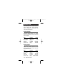
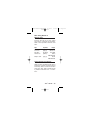
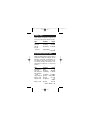
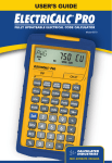
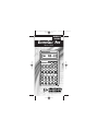
5060-UG-B-Composite
4/4/03
12:37 PM
USER’S
GUIDE
ELECTRICALC PRO
®
MODEL 5060
3O 60
Cu
VD
WIRE SIZE
125%
CONSTRUCTION MASTER ®
ELECTRICALC PRO
®
Off
On/C
Cond Type
CondSz
#THW
#XHHW
#THHN
VD%
Starter
SEFuse
InsTrip
M–Type
Wire Res
HP motor
DEFuse
InvTime
O-Load
Length
Eff%
milli–
EqGrnd
D/R Size
125%
HP th
kilo–
Grnd
ParSz
WireSz
VA
Volts
Amps
75 °
Ind/Sync
90 °
7
8
9
PF%
Watts
Set
___
√x
DC Res
Cu/Al
FrAir
60 °
Stor
4
5
6
M–R/C
1Ø
Amb °
3Ø
Rcl
1
2
3
x2
M+
%
0
Prefs
AC
π
+/–
Page 1
5060-UG-B-Composite
4/4/03
12:37 PM
Page 2
5060-UG-B-Composite
4/4/03
12:37 PM
Introducing the
ElectriCalc® Pro
Now NEC ®-Updateable!
The ElectriCalc ® Pro is an invaluable
calculator for today’s busy electrical
professional. Unlike a regular calculator, it has intuitively labeled “electrical
keys” and conforms to the 2002 and
future National Electrical Codes, allowing you to solve Code-related problems
quickly and accurately. The most common NEC tables are now at your fingertips!
An important new feature of the ElectriCalc Pro is that it is now programmed
to accept future NEC changes, allowing
you to conveniently install future Code
editions in a few simple steps.
User’s Guide — 1
Page 3
5060-UG-B-Composite
4/4/03
12:37 PM
The ElectriCalc Pro instantly solves for
the following:
♦
Volts, Amps, Volt-Amps, Watts,
kVA, kW, PF%, EFF%, and DC
Resistance
♦
Copper or Aluminum Wire Sizes
♦
Parallel & Derated Wire Sizes
♦
Voltage Drop Wire Sizes, % and
Actual Voltage Drops, Voltage
Drop Distances and Wire Resistances
♦
Grounding Conductors Sizes
♦
Motor Full-Load Amps
♦
Overload Protection Sizes
♦
NEMA Starter Sizes
♦
Conduit Sizes
♦
And much more!
2 — ElectriCalc Pro
Page 4
5060-UG-B-Composite
4/4/03
12:37 PM
Table of Contents
Installing NEC Updates . . . . . . . . . . . . . .4
Key Definitions . . . . . . . . . . . . . . . . . . .5
Preference Settings . . . . . . . . . . . . . . .26
Default Settings . . . . . . . . . . . . . . . . .27
Basic Math Operations . . . . . . . . . . . . .28
Percent Calculations . . . . . . . . . . . . . .28
Memory Functions . . . . . . . . . . . . . . . .29
Kerchoff’s Law . . . . . . . . . . . . . . . . . .30
Motor Horsepower . . . . . . . . . . . . . . . .34
Ampacity Wire Sizing . . . . . . . . . . . . . .36
Voltage Drop . . . . . . . . . . . . . . . . . . .42
Ground Conductor Wire Size . . . . . . . . .48
Equip. Grounding Conductor Wire Size . .49
Fuse and Circuit Breaker Size . . . . . . . .50
Starter Size . . . . . . . . . . . . . . . . . . . .51
Overload Protection Size . . . . . . . . . . . .51
Conduit Size . . . . . . . . . . . . . . . . . . . .52
Error Codes . . . . . . . . . . . . . . . . . . . .57
Battery Information . . . . . . . . . . . . . . .57
2002 NEC References . . . . . . . . . . . . . .58
Updating Future Code Revisions . . . . . . .58
Settings . . . . . . . . . . . . . . . . . . . . . . .59
Warranty . . . . . . . . . . . . . . . . . . . . . .60
Legal Notices . . . . . . . . . . . . . . . . . . .64
User’s Guide — 3
Page 5
5060-UG-B-Composite
4/4/03
12:37 PM
Installing NEC Updates
Your ElectriCalc Pro is now updateable
for future National Electrical Code®
editions that are updated every three
(3) years (next Code update is 2005).
To upgrade your unit, follow the instructions below:
1) Purchase the NEC Update from CI
(see pricing & details from CI’s Web
site: www.calculated.com or call 1800-854-8075). This Update is in the
form of a chip that contains the new
Code.
2) Once you receive the NEC Update
chip, you need to install it in your
ElectriCalc Pro:
a) Turn calculator off.
b) As a precaution, remove the battery (located back of calculator, top
of unit) by sliding battery door out
with your thumbnail. Set aside.
c) Using a screwdriver, pop out the
square tab located in the middle
section on the back of your calculator.
d) Replace it with the new Update tab
by inserting it into the slot.
e) Replace the battery door.
f) Turn calculator on. Your calculator
is now updated and ready to use.
4 — ElectriCalc Pro
Page 6
5060-UG-B-Composite
4/4/03
12:37 PM
Key Definitions
Standard Calculator Functions
[On/C] — On/Clear
Turns on power. Pressing once clears
the last entry and the display. Pressing
twice clears all non-permanent values.
[Off] — Off
Turns all power off. Clears the memory
and most internal registers.
[+] [–] [x] [÷] [=]
Arithmetic operation keys.
[0] – [9] & [•]
Used for keying in numbers.
[%] — Percent
Four function percent key.
[
] Back Space Function
Used to delete entries one keystroke at
a time (unlike the On/C function, which
deletes the entire entry).
User’s Guide — 5
Page 7
5060-UG-B-Composite
4/4/03
12:37 PM
[Set] — Second Function
Accesses the secondary functions
shown above the keys when pressed
prior to selection.
[Stor] — Store
Used to store values when pressed just
before a storage register (i.e., M+,
AMPS, VOLTAGE, etc.).
Displays: STOR.
[Rcl] — Recall
Recalls a value stored in a register
(e.g., to recall voltage drop % press
[Rcl] [VD%]). Displays: RCL.
[Set] [ + ] — Pi (π)
Constant = 3.141593
[Set] [–] — Change Sign (+/–)
Toggles the sign of the displayed value
(from positive to negative or from negative to positive).
[Set] [%] — x2
Squares the displayed value.
[Set] [
] — Square Root ( x )
Square root function.
6 — ElectriCalc Pro
Page 8
5060-UG-B-Composite
4/4/03
12:37 PM
[Stor] [0] — Cumulative Memory
Adds displayed value to Memory (e.g.,
10 [M+], 20 [M+], [Rcl] [M+] = 30).
Clears when the calculator is shut off.
[Rcl] [0] — Memory Recall
Displays the value saved in (M+).
[Rcl] [Rcl] — Display/Clear Memory
Displays and clears the value saved in
(M+).
[Set] [Rcl] — Clear Memory
Clears the value saved in (M+) without
changing displayed value.
Mode Set-up Functions
[Set] [x] — All-Clear (AC)
Resets all settings and values to their
default settings.
[Set] [÷] — Preferences
Use to set default settings or modes
(see “Preference Settings” page 26)
[Set] [1] — Single-Phase (1Ø)
Sets calculator to single-phase mode.
Displays: 1Ø.
User’s Guide — 7
Page 9
5060-UG-B-Composite
4/4/03
12:37 PM
[Set] [3] — Three-Phase (3Ø)
Sets calculator to three-phase mode.
Displays: 3Ø.
[Set] [2]
— Ambient Temperature (Amb°)
Permanently enters ambient temperature for determining ampacity derived
wire sizes. Ambient temperature will
only change when entering a new value
or by resetting the calculator ([Set] [x]).
Defaults to 30°C (86°F). Amb° will
display when the ambient temperature
is other than 30°C (86°F). Displays:
Amb°.
NOTE: The temperature units can be
displayed in Celsius (°C) or Fahrenheit
(°F) by using the preference function
([Set][÷]).
[Set] [4] — Copper/Aluminum
Used to toggle between copper (default) and aluminum wire types. When
the wire type is revised, any calculated
wire size will be re-calculated automatically. If a wire size is entered with the
wrong wire type, pressing [Set] [4] will
change the material type without
changing the size.
Displays: Al or Cu.
8 — ElectriCalc Pro
Page 10
5060-UG-B-Composite
4/4/03
12:37 PM
[Set] [5] — Free Air (FrAir)
Sets calculator into Free Air mode,
which refers to NEC Table 310-17 for
wire size calculations. Displays: FrAir.
[Set] [6] — 60°C Wire Insulation
Sets calculator to 60°C wire insulation
type for wire size calculations. This is
the default setting. Displays: 60.
[Set] [7] — 75°C Wire Insulation
Sets calculator to 75°C insulation type
for wire size calculations.
Displays: 75.
[Set] [9] — 90°C Wire Insulation
Sets calculator to 90°C insulation type
for wire size calculations.
Displays: 90.
Electrical Functions
[kilo-] — KiloThis key is used with watts, amps,
volts, and volt-amps to identify “kilo-”
values.
[Set] [kilo-] — MilliThis key sequence is used with other
keys watts, amps, volts, and volt-amps
to identify “milli-” values.
User’s Guide — 9
Page 11
5060-UG-B-Composite
4/4/03
12:37 PM
[Amps] — Amps
Enters or calculates amps (using volts
and VA or watts). Displays: AMPS,
KAMP or mAMP.
[Volts] — Volts
Enters or calculates volts (using amps,
HPth, and VA or watts). Default value is
240 volts. Displays: VOLT, KV, or mV.
[Set] [Volts] — DC Resistance
Calculates and displays DC resistance.
Displays: OHMS.
[VA] — Volt-Amps
Enters or calculates volt-amps (using
amps, volts and horsepower or watts).
Displays: VA, KVA, or mVA.
[Watts] — Watts
Enters or calculates watts (using amps,
volts, and VA or horsepower).
Displays: WATT, KW, or mW.
[Set] [Watts] —Power Factor
Enters or calculates power factor percentage (based on watts and VA). Defaults to 100%. Entered or calculated
power factors greater than 100% will
result in an error. Displays: PF%.
10 — ElectriCalc Pro
Page 12
5060-UG-B-Composite
4/4/03
12:37 PM
[HPth] — Horsepower (Theoretical)
Enters or calculates theoretical horsepower (based on Amps, VA, watts,
efficiency%, PF%, and/or volts). 1.0
HPth correlates to 746 watts at 100%
efficiency. Displays: HPth.
[Set] [HPth] — Efficiency
Enters or calculates the percent ratio
between real power (watts) and theoretical horsepower. Default: 100%.
Entered or calculated efficiencies
greater than 100% will result in an error. Displays: EFF%.
Motor Horsepower Functions
The ElectriCalc Pro can be used to
determine motor full-load current
(amps) based on entries for motor
horsepower (HP), phase and voltage.
You can also find an equivalent motor
horsepower if you have entered voltage
and full load current values. Only HP
and voltage entries as defined by NEC
Tables 430-148 and 430-150 can be
used to determine motor loads.
User’s Guide — 11
Page 13
5060-UG-B-Composite
4/4/03
12:37 PM
[Set] [8] — Induction/
Synchronous Motor Toggle
Toggles between induction and synchronous motor types. Displays: SYNC
(synchronous) or IND (induction - default).
[HPmotor] — Motor Horsepower
Enters or calculates motor horsepower.
Displays: SYNC HP (synchronous) or
HP IND (induction - default).
Ampacity Tables
The ElectriCalc Pro uses NEC Table
310-16 (310-17 for Free Air) to find wire
sizes and ampacity ratings of wires.
The calculator uses the following data
to calculate wire size: 1) insulation
temperature rating (60°C, 75°C and
90°C); 2) wire material (copper or aluminum); and 3) ambient temperature.
Only standard AWG wire sizes are
used by the ElectriCalc Pro.
NOTE: 1/0, 2/0, 3/0 and 4/0 wires are
entered using the [0] key (i.e., 0, 00,
000 and 0000).
[WireSz] — Wire Size/Ampacity
Enters or calculates wire size based on
ampacity and voltage drop, if a voltage
drop length has been entered.
12 — ElectriCalc Pro
Page 14
5060-UG-B-Composite
4/4/03
12:37 PM
♦ First Press
If a wire length has been entered, the
first press will show the larger of the
ampacity or voltage drop derived wire
size. The calculator will use the larger
value when calculations require a wire
size. If no voltage drop length has been
entered, the calculator will display the
calculated ampacity rated wire size.
♦ Second Press
If a wire length has been entered, the
second press displays the smaller of
the two wire sizes. If not solving for
voltage drop wire size, then displays
the maximum ampacity.
♦ Third Press
If a wire length has been entered, displays the minimum wire ampacity rating.
[Set] [WireSz] — 125% Ampacity
Used for motor wire sizing when the
wire must not exceed 80% of its rated
ampacity (125%A). This keystroke
calculates wire size based on 125% of
the entered or calculated amps value.
Displays: 125%.
User’s Guide — 13
Page 15
5060-UG-B-Composite
4/4/03
12:37 PM
[ParSz] — Parallel Size
Used to find the size of parallel conductors using amperage and an entered
quantity of wires. Parallel wire size
computations smaller than 1/0 are displayed as “none” (display shows
“nonE”) as the NEC does not allow
parallel wire runs smaller than 1/0.
♦ First Press
When preceded by a number, calculates the applicable wire size for that
quantity of wires in parallel.
Displays: PAR WIRE SIZE.
♦ Second Press
Displays the maximum adjusted ampacity of the calculated parallel wire
size. Displays: WIRE A.
NOTE: No adjustments are made for
deration.
[Set] [ParSz] — Derated Wire Size
Used to calculate derated wire sizes
and allowable ampacity based on the
entered quantity of wires, NEC Table
310-16 and NEC Table 310-15(b)(2)(a).
Derated wire sizes are not calculated
when there are less than 4 wires, or
when the unit is in Free Air mode.
14 — ElectriCalc Pro
Page 16
5060-UG-B-Composite
4/4/03
12:37 PM
♦ First Press
Calculates the derated wire size, if you
have entered the number of wires, for
example, 4 [Set] [ParSz]).
Displays: D/R WIRE SIZE.
♦ Second Press
Displays the maximum adjusted ampacity of the derated wire size.
Displays: D/R WIRE A.
♦ Third Press
Displays the derated adjustment factor
per the NEC Table 310-15(b)(2)(a).
Displays: ADJ %.
Voltage Drop Solutions
The ElectriCalc Pro will calculate
maximum lengths, minimum wire sizes
or actual voltage drops given the other
two values. Voltage drop solutions are
based on the DC resistance values
found in NEC Chapter 9, Table 8.
NOTE: Voltage drop solutions may vary
slightly from actual AC circuit values as
the calculator does not incorporate
factors such as inductive reactance,
skin effect, raceway material, etc.
User’s Guide — 15
Page 17
5060-UG-B-Composite
4/4/03
12:37 PM
[VD%] — Percent Voltage Drop
Used to enter or calculate voltage drop.
The default voltage drop is 3%. If wire
size or wire length values are not available, “nonE” will display since the voltage drop cannot be found.
♦ First Press
Enters a maximum allowable voltage
drop percentage (Displays: V DROP
%) or calculates actual voltage drop
(Displays: V DROP).
♦ Second Press
Calculates actual percent voltage drop.
Displays: V DROP %.
[Length] — Length
Enters or calculates the length of a run
for voltage drop computation.
Displays: FEET or MET.
NOTE: Units of length can be set to
Feet or Meters by use of the Preference function ([Set] [÷]).
[Set] [Length] — Wire Resistance
Displays the actual resistance per
1,000 feet of the wire size in [WireSz]
based on NEC Chapter 9, Table 8.
Displays: OHMS WIRE.
16 — ElectriCalc Pro
Page 18
5060-UG-B-Composite
4/4/03
12:37 PM
Ground Function Keys
[Grnd] — Ground
An output-only key used to find the
grounding electrode conductor size for
AC systems based on NEC Table
250-66 and an entered or calculated
service-entrance conductor (largest
size). Only actual wire sizes are considered valid entries.
♦ First Press
Calculates the copper grounding electrode conductor size if you have entered a valid wire size.
Displays: GRND CU WIRE SIZE.
♦ Second Press
Displays the aluminum grounding electrode conductor size.
Displays: GRND AL WIRE SIZE.
♦ Third Press
Displays the circular mil area used to
calculate the grounding electrode conductor size. Displays: CMIL WIRE.
User’s Guide — 17
Page 19
5060-UG-B-Composite
4/4/03
12:37 PM
[Set] [Grnd]
— Equipment Ground (EqGrnd)
This function uses NEC Table 250-122
to compute the minimum equipment
grounding conductor size, given an
entered amperage rating or setting for a
over-current device up line (i.e., 300
[Set] [Grnd]).
NOTE: This function deviates from the
NEC Table 250-122 in that 1250 MCM
AL is used instead of 1200 as specified
in NEC Table 250-122.
♦ First Press
Displays the copper grounding conductor size for the entered amp rating.
Displays: EQPG WIRE SIZE CU.
♦ Second Press
Displays the aluminum grounding conductor size.
Displays: EQPG WIRE SIZE AL.
18 — ElectriCalc Pro
Page 20
5060-UG-B-Composite
4/4/03
12:37 PM
Fuse/Breaker Keys
The ElectriCalc Pro has special keys
that automatically calculate the Amp
ratings of the following over-current
protection devices: Dual Element Fuses
(Time Delay), Single Element Fuses
(Non-Time Delay), Instantaneous Trip
Breakers (Type 1), Inverse Time
Breakers (Type 2), and Overload
Protection Devices.
These fuse and circuit breaker sizes
are derived using the “Percent of FullLoad Current” multipliers listed in NEC
Table 430-152.
You can also calculate the full voltage
starter size for non-plugging and nonjogging duty motors based on phase,
voltage, motor HP and NEMA table
specifications.
If a parameter is missing or invalid, the
calculator will display “nonE.”
[Set] [O-Load] — Motor Type
Based on NEC Table 430-152, this key
selects the motor type used to define
the percent factors for breakers/fuses.
Once set, the motor type remains fixed
until you change it or perform an all
clear ([Set] [x]).
User’s Guide — 19
Page 21
5060-UG-B-Composite
4/4/03
12:37 PM
♦ First Press
Displays the current motor type. Note
there is no motor type in single-phase
mode.
♦ Second Press
In three-phase mode only, subsequent
presses of [O-Load] will select and
display the next motor type from this
list: SQ-C non-E (Squirrel Cage, nonDesign E), SQ-C E (Squirrel Cage,
Design E), SYNC no codE (Synchronous), WND no codE (Wound Rotor).
[DEFuse] — Dual Element Fuse
♦ First Press
Calculates the minimum amp rating for
a Dual Element Fuse.
Displays: AMPS dE.
♦ Second Press
Displays the full-load current percent
multiplier used to determine fuse size.
Displays: %FLC.
[Set] [DEFuse]
— Single Element Fuse (SEFuse)
♦ First Press
Displays the minimum amp rating
based on phase, motor type, and amperage. Displays: AMPS SE.
20 — ElectriCalc Pro
Page 22
5060-UG-B-Composite
4/4/03
12:37 PM
♦ Second Press
Displays the full-load current percent
multiplier value used to determine fuse
size. Subsequent presses repeat this
cycle. Displays: %FLC.
[Set] [InvTime] — Instantaneous
Trip Circuit Breaker
♦ First Press
Displays the minimum amp rating for
an Instantaneous Trip Circuit Breaker,
based on the phase, motor type, and
amperage. Displays: AMPS b1.
♦ Second Press
Displays the full-load current percent
multiplier value used to determine
breaker size. Displays: %FLC.
[InvTime] — Inverse Time Breaker
♦ First Press
Calculates the minimum amp rating for
an Inverse Time Breaker, based on the
phase, motor type, and amperage.
Displays: AMPS b2.
♦ Second Press
Displays the full-load current percent
multiplier value used to determine
breaker size. Displays: %FLC.
User’s Guide — 21
Page 23
5060-UG-B-Composite
4/4/03
12:37 PM
[O-Load] — Overload Protection
♦ First Press
Displays the overload amperage requirement based on the full-load current shown on the motor nameplate.
Multiplies the entered motor nameplate
full-load current (stored in the [Amps]
registers) by 115% or the value you
enter. Conforms to NEC Section 43032 (a)(1) value of 115% unless you
enter another value. For example, entering 125 [O-Load] would calculate
overload protection based on 125% of
the entered amperage. Displays:
AMPS ol.
♦ Second Press
Displays the full-load current percent
multiplier value used to determine the
overload current protection size. Subsequent presses of [O-Load] repeat the
cycle. Displays: %FLC.
[Set] [HPmotor] — Starter Size
Displays the starter size (from NEMA
publication ICS 2-1988 Tables 2-327-1
and 2-327-2) based on the phase, voltage, and motor horsepower settings.
Displays: STAR SIZE.
NOTE: Horsepower values not identified in NEMA tables will cause the calculator to round up to the next larger
starter size in the table.
22 — ElectriCalc Pro
Page 24
5060-UG-B-Composite
4/4/03
12:37 PM
Conduit Sizing Keys
The ElectriCalc Pro calculates conduit
size using NEC Tables 1, 3, 4, and 5 of
Chapter 9 (given insulation type, wire
size, and quantity of wires). It will also
calculate the number of wires of a
specified insulation type and wire size
that will fit in a defined conduit size.
Acceptable conduit sizes (depending
on the type of conduit used) are as
follows: 1/2”, 3/4”, 1”, 1-1/4”, 1-1/2”, 2”,
2-1/2”, 3”, 3-1/2”, 4” 5” and 6”. Conduit
sizes are entered using decimal equivalents (i.e., 1-1/2” is entered as 1.5, 3/4”
is entered as .75, etc.).
[#THW], [#XHHW], [#THHN]
— Number of Wires
Used to enter or calculate the number
of wires in a raceway and calculate
cross-sectional wire area.
♦ First Press
Enters number of wires or calculates
maximum number of wires in conduit.
Displays: TTL WIRES (calculated) or
WIRES (entered).
♦ Second Press
Shows total cross-sectional area for all
entered wires. Displays: WIRE AREA
(entered) or TTL WIRE AREA (calculated).
User’s Guide — 23
Page 25
5060-UG-B-Composite
4/4/03
12:37 PM
♦ Third Press
Shows total cross-sectional area of all
entered wires of the selected wire insulation. Displays: TTL WIRE AREA.
[CondSz] — Conduit Size
Used to find conduit sizes based on the
total area of the entered wire types and
sizes (up to 15 at one time). If the
quantity and insulation type has not
been entered, the calculator will assume 2 THHN wires for single-phase or
3 THHN wires for three-phase calculations.
♦ First Press
Enters or calculates conduit size.
Displays: COND SIZE.
NOTE: If a wire size has not been entered or calculated, or an invalid conduit size is entered, the calculator will
display “nonE.”
♦ Second Press
Shows total number of wires in the
conduit for calculated conduit size.
Shows the conduit internal area for an
entered conduit. Displays: TTL WIRES
(calculated) or CONDAREA (entered).
NOTE: Third through fifth presses display only for calculated conduit sizes.
24 — ElectriCalc Pro
Page 26
5060-UG-B-Composite
4/4/03
12:37 PM
♦ Third Press
Shows fill percentage for the calculated
conduit size as determined by Table 1,
Chapter 9. Displays: COND FILL %.
♦ Fourth Press
Shows the total wire area for all entered
wires. Displays: FILL TTL WIRE AREA.
♦ Fifth Press
Shows remaining fill area. This value
may be negative if all wires are the
same size due to Note 7 in NEC Chapter 9, Table 1.
Displays: REM WIRE AREA.
[Set] [CondSz] — Conduit Type
♦ First Press
Displays the currently selected conduit
type.
♦ Second Press
Subsequent presses will display and
select the next conduit type from this
list: 1) EMT 2) ENT 3) FMC 4) IMC
5) LFNB 6) LFNA 7) LFMC 8) RMC
9) P-80 10) P-40 11) P-A 12) P- EB.
To select a specific conduit type, enter
the corresponding number of the conduit and then press [Set] [CondSz]. If
you press this keystroke without entering a number, the calculator will switch
to the next conduit type on the list.
User’s Guide — 25
Page 27
5060-UG-B-Composite
4/4/03
12:37 PM
Preference Settings
Your calculator has the following Preference Settings that you can access
and change at any time.
Reach the Preference Function by
pressing [Set] [÷]. Then, to access
each category, press the [÷] key until
the desired setting is reached. Within
each category, press the [+] or [-] keys
to toggle between individual selections
(note: the [+] will advance, the [-] will
back-up).
You can change these settings at any
time by repeating the above, and setting in a new preference. NOTE: To
clear preferences, you must either reset
using keystrokes below, or perform an
All-Clear ([Set] [x]).
The Preference Settings are (default
settings shown first):
To Set 1999 or 1996 NEC Code:
[Set] [÷] (1st press of [÷])
CODE 99
[+]
CODE 96
To Set Ambient Temp. to °C or °F:
[÷] (2nd press of [÷])
AMB° 30 °C
[+]
AMB° 86 °F
To Set Length to Feet or Meter:
[÷] (3rd press of [÷])
FEET 1.
[+]
MET 1.
26 — ElectriCalc Pro
Page 28
5060-UG-B-Composite
4/4/03
12:37 PM
Default Settings
When you first receive your calculator,
it is pre-set to the default settings listed
below. You can always return your
calculator to these default values with
an All-Clear ([Set] [x]).
Ambient Temperature
30°C
Insulation Rating
60°C
Material
Copper (Cu)
Phase
3Ø
Volts
240 V
Efficiency
100%
Power Factor
100%
Length Units
Feet
Voltage Drop Percent
3%
Wire Environment
(vs Free Air)
Raceway
User’s Guide — 27
Page 29
5060-UG-B-Composite
4/4/03
12:37 PM
Basic Math Operations
This calculator uses standard chaining
logic, which simply means that you
enter your first value, the operator (+, –,
x, ÷), the second value and then the
equals sign (=).
A.
B.
C.
D.
3
3
3
3
[+]
[–]
[x]
[÷]
2
2
2
2
[=]
[=]
[=]
[=]
5
1
6
1.5
Percent Calculations
The percent key [%] can be used for
finding a given percentage of a number
or for working add-on, discount or division percentage calculations.
355
250
25
100
[x]
[+]
[–]
[÷]
15
6.5
5
50
[%]
[%]
[%]
[%]
53.25
266.25
23.75
200.
The percent key also allows you to
change percentages to decimals (e.g.,
25 [%] 0.25).
28 — ElectriCalc Pro
Page 30
5060-UG-B-Composite
4/4/03
12:37 PM
Memory Functions
Whenever the [Stor] [0] (M+) keys are
pressed, the displayed value will be
added to memory. A list of memory
keystrokes/functions is provided below:
Function Keystrokes
Add to memory
[Stor] [0]
Display total in memory
[Rcl] [0]
Display & clear memory
[Rcl] [Rcl]
Clear memory, no display [Set] [Rcl]
Replace memory with
displayed value [Set] [Rcl] [Stor] [0]
The memory is semi-permanent; it will
be cleared when you:
1)
2)
3)
4)
turn off the calculator;
press [Rcl] [Rcl];
press [Set] [Rcl];
press [Set] [x] (all clear).
How To Use Memory Functions:
Steps
Keystrokes
Display
Reset calculator
Add to M+
Add to M+
Recall total M+
Sub. from M+
[On/C]
355 [Stor] [0]
255 [Stor] [0]
[Rcl] [0]
745 [Set]
[Stor] [0]
[Rcl] [Rcl]
0.
355. M
255. M
610. M
Recall & clear
745. M
– 135.
User’s Guide — 29
Page 31
5060-UG-B-Composite
4/4/03
12:37 PM
Kerchoff’s Law
The ElectriCalc Pro utilizes Kerchoff’s
Law in finding volts, amps, volt-amps,
watts, horsepower (theoretical), efficiency and power factor.
Finding Voltage
Find the voltage supply to a singlephase load drawing 14,605 volt-amps
and 115 amps.
Steps
Keystrokes
Clear calculator
Set to 1-phase
Enter VA
Enter amps
Solve for volts
[On/C] [On/C]
[Set] [1]
14605 [VA]
115 [Amps]
[Volts]
Display
0.
1 PH
14,605. VA
115. AMPS
127. VOLT
Finding Amps
What is the current (amps) for a load
drawing 8,250 volt-amps on a 240 volt,
three-phase circuit?
Steps
Keystrokes
Display
Clear calculator
Set to 3-phase
Enter VA
Enter volts
Solve for amps
[On/C] [On/C]
0.
[Set] [3]
3 PH
8250 [VA]
8,250. VA
240 [Volts]
240. VOLT
[Amps] 19.846416 AMPS
30 — ElectriCalc Pro
Page 32
5060-UG-B-Composite
4/4/03
12:37 PM
Finding Current Load
A building with 120/240 volt 1Ø service
has the following loads:
Range = 7,800 VA
Dryer = 5,100 VA
Lighting = 6,470 VA
Heating = 15,100 VA
Appliances = 8,900 VA
What is the service load (amps) of the
circuit supplying this building?
Steps
Keystrokes
Clear calculator
Set to 1-phase
Add VA loads:
[On/C] [On/C]
0.
[Set] [1]
1 PH
7,800 + 15,100 +
5,100 + 8,900 +
6,470 [=]
43,370.
[VA]
43,370. VA
240 [Volts]
240. VOLT
[Amps] 180.70833 AMPS
Enter as VA
Enter volts
Solve for amps
Display
Finding Amps from Kilowatts
What is the amperage for a 75 kW load
connected in a 120/208 volt, 3Ø circuit?
Steps
Keystrokes
Display
Clear calculator
Set to 3-phase
Enter kilowatts
Enter volts
Solve for amps
[On/C] [On/C]
0.
[Set] [3]
3 PH
75 [kilo-] [Watts] 75. KW
208 [Volts]
208. VOLT
[Amps] 208.17918 AMPS
User’s Guide — 31
Page 33
5060-UG-B-Composite
4/4/03
12:37 PM
Finding Volt-Amps
What is the VA rating for a 120 volt, 22
amp, 1Ø circuit? What is the kVA rating?
Steps
Keystrokes
Clear calculator
Set to 1-phase
Enter volts
Enter amps
Solve volt-amps
Solve for kVA
[On/C] [On/C]
[Set] [1]
120 [Volts]
22 [Amps]
[VA]
[kilo-] [VA]
Display
0.
1 PH
120. VOLT
22. AMPS
2,640. VA
2.64 KVA
Finding kVA Rating
What is the kVA rating for a 120/208
volt, three-phase 65 amp transformer?
Steps
Keystrokes
Reset calculator
Enter volts
Enter amps
Solve for kVA
[Set] [x] [On/C]
0.
208 [Volts]
208. VOLT
65 [Amps]
65. AMPS
[kilo-] [VA] 23.417327 KVA
32 — ElectriCalc Pro
Display
Page 34
5060-UG-B-Composite
4/4/03
12:37 PM
Finding Wattage
A 120 volt single-phase 45 amp electrical motor has an 87% power factor.
What is its wattage?
Steps
Keystrokes
Display
Clear calculator
Set to 1-phase
Enter volts
Set power fact %
Enter amps
Solve for watts
[On/C] [On/C]
0.
[Set] [1]
1 PH
120 [Volts]
120. VOLT
87 [Set] [Watts] 87. PF%
45 [Amps]
45. AMPS
[Watts]
4,698. WATT
Finding kW Rating
What’s the kW rating for a 90 amp, 208
volt, three-phase broiler with 100%
power factor?
Steps
Keystrokes
Clear calculator
Set to 3-phase
Set power factor
Enter amps
Enter volts
Solve for kW
[On/C] [On/C]
0.
[Set] [3]
3 PH
100 [Set] [Watts] 100. PF%
90 [Amps]
90. AMPS
208 [Volts]
208. VOLT
[kilo-] [Watts] 32.423991 KW
Display
User’s Guide — 33
Page 35
5060-UG-B-Composite
4/4/03
12:37 PM
Motor Horsepower
The ElectriCalc Pro can calculate the
full load current (amps) of a motor,
based on phase, voltage and motor
(synchronous or induction). It uses
NEC Tables 430-148 and 430-150 to
determine the motor full load current. (If
you enter a value for HP or voltage that
does not correspond to these tables,
the unit will display Error 8).
The ElectriCalc Pro can also calculate
an equivalent horsepower for either an
induction or a synchronous motor
based on a voltage, phase and full load
current. When calculating motor HP
from an entered amperage, a result not
directly matching a value in NEC Table
430-148 or 430-150 will cause the calculator to choose the next higher table
value for motor horsepower.
34 — ElectriCalc Pro
Page 36
5060-UG-B-Composite
4/4/03
12:37 PM
Finding Single-Phase Full Load
Current
A 2 HP induction motor operates on 230
volt, single-phase power. What is the full
load current for this motor?
Steps
Keystrokes
Reset calculator
Set to 1-phase
Enter volts
Enter HPind
Find full load amps
[On/C]
[Set] [1]
230 [Volts]
2 [HPmotor]
[Amps]
Display
0.
1 PH
230. VOLT
2. HP IND
12. FLC A
Finding Motor Wire Size and
Ampacity
Find the wire size required to connect a
continuous run, 3Ø, 3 HP induction
motor into a 230V circuit.
Steps
Keystrokes
Display
Reset calculator
Enter volts
Enter HPind
Find load current
Find 125% A size
[Set] [x] [On/C]
0.
230 [Volts]
230. VOLT
3 [HPmotor]
3. HP IND
[Amps]
9.6 FLC A
[Set] [WireSz] 14 CU AWG
WIRE SIZE 125%
Find max ampacity [WireSz]
14 20.0
WIRE A125%
NOTE: Display will show wire size in the upper
left when displaying wire ampacity rating.
User’s Guide — 35
Page 37
5060-UG-B-Composite
4/4/03
12:37 PM
Finding Synchronous Motor
Horsepower
A synchronous motor is defined as
having a 27 amp load on a 240 volt, 3Ø
circuit. What is its horsepower?
Steps
Keystrokes
Display
Reset calculator
Set to synch.
Enter volts
Enter amps
Solve for Hp
[On/C]
[Set] [8]
240 [Volts]
27 [Amps]
[HPmotor]
0.
0. SYNC
240. VOLT
27. AMPS
25. HP SYNC
Ampacity Wire Sizing
The required wire size of a service
conductor can be determined based on
the specified electrical requirements
and the [WireSz] key. The wire size is
automatically recalculated whenever
the wire insulation (temperature) ratings
or wire material (copper or aluminum)
types are revised. Wire sizing is based
on the requirements defined in NEC
Tables 310-16 and 310-17.
36 — ElectriCalc Pro
Page 38
5060-UG-B-Composite
4/4/03
12:37 PM
Wire Sizing Based
on Insulation Rating
Wiring is being installed in a 240 volt,
single-phase system rated at 30 kVA.
What is the wire size needed if you use
60°C copper wire?
Steps
Keystrokes
Display
Clear calculator
Set to 1-phase
Set to 60˚C
Enter kVA
Enter volts
Find amps
Find CU wire size
[On/C] [On/C]
0.
[Set] [1]
1 PH
[Set] [6]
1Ø 60 Cu 1 PH
30 [kilo-] [VA]
30. KVA
240 [Volts]
240. VOLT
[Amps]
125. AMPS
[WireSz]
0 CU
AWG WIRE SIZE
Re-sizing Wire Based on
Different Insulation Ratings
What wire size is required for a 75°C
copper branch circuit carrying a load of
260 amps? What would the wire size be
if 90°C copper is used?
Steps
Keystrokes
Reset calculator
Set to 75°C
Enter amps
Find wire size
[Set] [x] [On/C]
0.
[Set] [7]
3Ø 75 Cu 0.
260 [Amps]
260. AMPS
[WireSz]
300 CU
AWG WIRE SIZE
[Set] [9]
0000 CU
AWG WIRE SIZE
User’s Guide — 37
Change to 90˚
Display
Page 39
5060-UG-B-Composite
4/4/03
12:37 PM
Wire Sizing Based
on Ambient Temperature
Find the 90°C aluminum wire size
needed to connect a 47,700 volt-amp
load to a 240 volt, single-phase source.
What is the adjusted wire size, if the
ambient temperature rating is changed
from the default 30°C to 40°C?
Steps
Keystrokes
Clear calculator
Set to 1-phase
Set to 90°C
Set toAl
Enter VA
Enter volts
Find amps
Find wire size
[On/C] [On/C]
0.
[Set] [1]
1 PH
[Set] [9] 1 Ø 90 Cu 1 PH
[Set] [4]
1 Ø 90 Al 1 PH
47700 [VA]
47,700. VA
240 [Volts]
240. VOLT
[Amps]
198.75 AMPS
[WireSz]
0000 AL
AWG WIRE SIZE
Change ambient
temperature
Find adjusted
wire size
Reset amb. temp
40 [Set] [2]
Display
AMB° 40.˚C
[WireSz]
250 AL
AWG WIRE SIZE
30 [Set] [2]
AMB° 30.˚C
*NOTE: Ambient temperature will remain at 40°C unless you change it or
perform an ALL CLEAR ([Set] [x]).
38 — ElectriCalc Pro
Page 40
5060-UG-B-Composite
4/4/03
12:37 PM
Wire Sizing Based on
Material Type
Find the wire size for a 75°C copper
wire carrying a 3Ø load of 265 amps.
What is the equivalent aluminum wire
size?
Steps
Keystrokes
Reset calculator
Set to 75°C
Enter amps
Find wire size
[Set] [x] [On/C]
0.
[Set] [7]
3Ø 75 Cu 0.
265 [Amps]
265. AMPS
[WireSz]
300 CU
AWG WIRE SIZE
[Set] [4]
400 AL
AWG WIRE SIZE
Change to alum.
Display
Sizing Parallel Conductors
What size 60°C insulated copper wire is
required for a single conductor carrying
a 500 amp load in a Free Air environment (30°C amb. temp.)? What size for
2 parallel conductors? For 3 conductors?
User’s Guide — 39
Page 41
5060-UG-B-Composite
(Cont’d)
Steps
Reset calculator
Set free air mode
Enter amps
Find 1 wire size
Find 2 wire size
Find 3 wire size
4/4/03
Keystrokes
12:37 PM
Display
[Set] [x] [On/C]
0.
[Set] [5] 3Ø 60 FrAir Cu 0.
500 [Amps]
500. AMPS
[WireSz]
500 CU
AWG WIRE SIZE
2 [ParSz]
000 CU
PAR WIRE SIZE
3 [ParSz]
0 CU
PAR WIRE SIZE
NOTE: Parallel wire sizes smaller than
1/0 will be displayed as nonE.
Finding Derated Wire Size
What is the derated wire size required
for nine 75°C copper wires, each carrying a maximum load of 65 amps?
Steps
Keystrokes
Reset calculator
Set to 75°C
Enter amps
Find normal
wire size
[Set] [x] [On/C]
0.
[Set] [7]
3Ø 75 Cu 0.
65 [Amps]
65. AMPS
Find derated
wire size
[WireSz]
Display
6 CU
AWG WIRE SIZE
9 [Set] [ParSz]
3 CU
D/R WIRE SIZE
40 — ElectriCalc Pro
Page 42
5060-UG-B-Composite
4/4/03
12:37 PM
Sizing Temperature-Adjusted
Derated Wires
A circuit was built with 90°C aluminum
wire connecting a 47,650 volt-amp load
to a 240 volt, single-phase source.
Ambient temperature is 50°C. What is
the derated wire size required if eight
current-carrying THHN wires were installed in the raceway?
Steps
Keystrokes
Reset calculator
Set to 1-phase
Set to 90°C
Toggle to alum.
Enter volt-amps
Enter volts
Set to 50°C amb
Find adjst wire sz.
[On/C]
0.
[Set] [1]
1 PH
[Set] [9]
1Ø 90 Cu 1 PH
[Set] [4]
1Ø 90 Al 1 PH
47650 [VA]
47,650. VA
240 [Volts]
240. VOLT
50 [Set] [2]
AMB° 50˚ C
[WireSz]
300 AL
AWG WIRE SIZE
8 [Set] [ParSz]
500 AL
D/R WIRE SIZE
Find derated
wire size
Display
NOTE: Ambient temperature should be
changed back to 30°C to avoid conflicts
in answers through out the rest of this
manual.
Reset to 30°C
30 [Set] [2]
AMB° 30˚ C
User’s Guide — 41
Page 43
5060-UG-B-Composite
4/4/03
12:37 PM
Voltage Drop
The reduction in voltage between the
power source and the load can be determined by entering the phase, volts,
amps, wire material, voltage drop wire
size and length of run. The calculator
determines resistance and then the
voltage reduction. Voltage drop can be
displayed as volts dropped, or as a
percent reduction of potential load.
This calculator also finds voltage drop
wire size once you have entered or
calculated the phase, volts, amps,
length, wire type, and allowable VD
percentage. It will solve for the distance
([Length]) once you have entered or
calculated the phase, volts, amps, wire
type, voltage drop wire size, and allowable VD percentage. The ElectriCalc
Pro uses resistance values found in
NEC Table 8 to determine voltage drop.
NOTE: Voltage drop solutions may vary
slightly from actual AC circuit measurements as the calculator does not
incorporate factors such as inductive
reactance, skin effect, raceway material, etc. In most situations, the DC
Voltage Drop calculation is sufficient to
meet safety standards.
42 — ElectriCalc Pro
Page 44
5060-UG-B-Composite
4/4/03
12:37 PM
IMPORTANT NOTE ON
VOLTAGE DROP CALCULATIONS
The ElectriCalc Pro calculates voltage
drop and wire size using DC resistance
as defined by the 2002 NEC. To find
the voltage drop for a specific wire size,
you must first enter amps and the oneway wire length (and other required
variables), entering the specific wire
size last. Otherwise, for your safety the
calculator will recalculate the wire sizes
based on the ‘99 NEC Ampacity Tables
and maximum allowable voltage drop.
Finding Single-Phase
Voltage Drop
You are installing 175 feet of 75°C, #8
THW branch circuit copper conductors
to supply an 11A load on a 208V 1Ø
system. What is the source voltage
drop at the load?
Steps
Keystrokes
Reset calculator
Set to 1-phase
Set to 75°C
Enter amps
Enter volts
Enter length
Enter wire size
[Set] [x] [On/C]
0.
[Set] [1]
1 PH
[Set] [7]
1Ø 75 Cu 1 PH
11 [Amps]
11. AMPS
208 [Volts]
208. VOLT
175 [Length]
175. FEET
8 [WireSz]
8 CU
AWG WIRE SIZE
[VD%]
3.0 DROP V
[VD%]
1.4 DROP V %
Solve volt. drop
Solve % v.drop
Display
User’s Guide — 43
Page 45
5060-UG-B-Composite
4/4/03
12:37 PM
Finding Three-Phase
Voltage Drop
A 20-amp three-phase load is being fed
by a 230-volt source located 150 feet
away. The installation specifications
require 75°C #10 THW stranded copper
conduc-tor. What is the voltage drop on
this branch circuit?
Steps
Keystrokes
Reset calculator
Set to 75°C
Enter amps
Enter volts
Enter length(feet)
Enter VD wire size10
[Set] [x] [On/C]
0.
[Set] [7]
3Ø 75 Cu 0.
20 [Amps]
20. AMPS
230 [Volts]
230. VOLT
150 [Length]
150. FEET
[WireSz]
10 CU
AWG WIRE SIZE
[VD%]
6.4 DROP V
[VD%]
2.8 DROP V %
Solve volt. drop
Solve % v.drop
44 — ElectriCalc Pro
Display
Page 46
5060-UG-B-Composite
4/4/03
12:37 PM
Finding Voltage Drop Wire Size
A 20-amp single-phase 208-volt load will
be located 175 feet away from the
source. Assuming a 3% allowable voltage drop, what is the size of 75°C conductor re-quired for this branch circuit?
Steps
Keystrokes
Reset calculator
Set to 75°C
Set to 1-phase
Enter amps
Enter volts
Enter distance
Enter allow. VD%
Find wire size
[On/C]
0.
[Set] [7]
3Ø 75 Cu 0.
[Set] [1]
1 PH
20 [Amps]
20. AMPS
208 [Volts]
208. VOLT
175 [Length]
175. FEET
3 [VD%]
3.0 DROP V %
[WireSz]
8 CU
AWG VD WIRE SIZE
Find actual
voltage drop
Find % v.drop
[VD%]
[VD%]
Display
5.4 DROP V
2.6 DROP V %
User’s Guide — 45
Page 47
5060-UG-B-Composite
4/4/03
12:37 PM
Finding Voltage Drop Distance
How far from a single-phase 240-volt
source can you install a 15 amp load
using 60°C #10 Al branch circuit conductors? Assume a 3% allowable voltage drop.
Steps
Keystrokes
Reset calculator
Set to 1-phase
Set to aluminum
Enter amps
Enter volts
Enter wire size
[Set] [x] [On/C]
0.
[Set] [1]
1 PH
[Set] [4]
1Ø 60 Al 1 PH
15 [Amps]
15. AMPS
240 [Volts]
240. VOLT
10 [WireSz]
10 AL
AWG WIRE SIZE
3 [VD%]
3.0 DROP V %
[Length] 123.77387 FEET
Enter 3% VD
Find distance
Find actual
voltage drop
Find % v.drop
[VD%]
[VD%]
Display
7.2 DROP AL V
3.0 DROP AL V %
NOTE: The calculator automatically
makes adjustments for resistance using
NEC Chap 9, Table 8, if the insulation
type is other than 75°C.
46 — ElectriCalc Pro
Page 48
5060-UG-B-Composite
4/4/03
12:37 PM
Finding Voltage Drop
Resistance
What is the resistance of 85 feet of #2
90°C copper conductor?
Steps
Keystrokes
Display
Reset calculator
[Set] [x] [On/C]
0.
Set to 90°C mode [Set] [9]
3Ø 90 Cu 0.
Enter wire size
2 [WireSz]
2 CU
AWG WIRE SIZE
Find resistance
[Set] [Length] 0.2033993
OHMS WIRE
Find 85 ft resist*
[÷] 1000 [x] 85 [=] 0.0172889
*NOTE: Given resistance per 1000 feet,
divide by 1000 to get a per foot resistance, then multiply by 85.
Finding DC Resistance
What is the equivalent resistance of a
12 volt DC circuit pulling 5 amps?
Steps
Keystrokes
Reset calculator
Enter voltage
Enter amps
Find resistance
[On/C]
12 [Volts]
5 [Amps]
[Set] [Volts]
Display
0.
12. VOLT
5. AMPS
2.4 OHMS
User’s Guide — 47
Page 49
5060-UG-B-Composite
4/4/03
12:37 PM
Ground Conductor Wire Size
You can use single or multiple service
entrance conductor(s) to find the
grounding electrode conductor for AC
systems. When using multiple conductors, the ElectriCalc Pro uses the
equivalent circular mils to find the
grounding electrode conductor (based
on NEC Table 250-66).
Find the grounding electrode conductor
wire size required when 2/0 is the largest 3-phase 75°C copper serviceentrance conductor being used. What
is the equivalent aluminum size? What
is the equivalent circular mils?
Steps
Keystrokes
Reset calculator
Set cond. temp.
Enter wire size
[On/C]
[Set] [7]
00 [WireSz]
Find grnd wire sz
[Grnd]
Find alum size
[Grnd]
Find circular mils
[Grnd]
48 — ElectriCalc Pro
Display
0.
3Ø 75 Cu 0.
00 CU
AWG WIRE SIZE
4 CU
GRND WIRE SIZE
2 AL
GRND WIRE SIZE
133,100.
CMIL WIRE
Page 50
5060-UG-B-Composite
4/4/03
12:37 PM
Equip. Grounding Conductor
Wire Size
The [Set] [Grnd] keystroke can be used
to find the grounding conductor size for
raceways and “over-current devices in
circuit ahead” equipment. The calculator uses the displayed amperage value
to solve for the equipment grounding
conductor based on NEC Table
250-122.
Find the equipment grounding conductor size required when the circuitbreaker is rated at 45 amps and 90°
copper is being used in the installation.
What is the equivalent aluminum size?
Steps
Keystrokes
Display
Reset calculator
Set cond. temp.
Enter amp rating
Find equip. grnd.
wire size
[On/C]
[Set] [9]
45 [Amps]
0.
3Ø 90 Cu 0.
45. AMPS
Find alum size
[Set] [Grnd]
10 CU
EQPG WIRE SIZE
[Grnd]
8 AL
EQPG WIRE SIZE
User’s Guide — 49
Page 51
5060-UG-B-Composite
4/4/03
12:37 PM
Fuse and Circuit Breaker Size
What is the computed dual element
and single element fuse size for a 230
volt, 3-phase, 50 HP induction motor?
What are the Instantaneous Trip and
Inverse Time Circuit Breaker requirements?
Steps
Keystrokes
Reset calculator
Enter volts
Enter hp
Find full current
Find DE fuse size
[On/C]
230 [Volts]
50 [HPmotor]
[Amps]
[DEFuse]
Display
0.
230. VOLT
50. HP IND
130. FLC A
227.5
dE AMPS
Display % used
[DEFuse]
175. %FLC
Find SE fuse size [Set] [DEFuse]
390.
SE AMPS
Display % used
[DEFuse]
300. %FLC
Find inv. time brkr [InvTime]
325. b2 AMPS
Display % used
[InvTime]
250. %FLC
Find ins. trip
breaker sz.
[Set] [InvTime]
1,040.
b1 AMPS
Display % used
[InvTime]
800. %FLC
50 — ElectriCalc Pro
Page 52
5060-UG-B-Composite
4/4/03
12:37 PM
Starter Size
What NEMA size starter is required for
a 575 volt, 3Ø, 20 HP induction motor?
Steps
Keystrokes
Reset calculator
Enter volts
Enter hp
Solve for
starter size
[On/C]
575 [Volts]
20 [HPmotor]
Display
0.
575. VOLT
20. HP IND
[Set] [HPmotor]
2
STAR SIZE
Overload Protection Size
What overload protection device size is
required for a 460 volt, 3-phase, 15 HP
induction motor with a nameplate current rating of 19.2 amps and a 1.0 service factor? What is the required overload rating at 125% (for a 1.15 service
factor)?
Steps
Keystrokes
Reset Calculator
Enter volts
Enter horsepower
Enter nameplate
current
Find overload size
Display % used
Find 125% load
[On/C]
460 [Volts]
15 [HPmotor]
Display % used
Display
0.
460. VOLT
15. HP IND
19.2 [Amps]
19.2 AMPS
[O-Load]
22.08 ol AMPS
[O-Load]
115. %FLC
125 [O-Load]
24.
ol AMPS
[O-Load]
125 %FLC
User’s Guide — 51
Page 53
5060-UG-B-Composite
4/4/03
12:37 PM
Conduit Size
The ElectriCalc Pro can calculate the
size of conduit required when running
single or multiple wires using the
[CondSz] key and the calculator’s internal tables. The calculator uses NEC
values for area of THW, THHN, and
XHHW wires. When using the actual
wire areas (and following the guidelines
in NEC Chapter 9, Tables 1, 3, 4 and
5), the calculator can calculate a conduit size based on the conduit type and
the same or different wire types and
sizes.
To select a specific conduit type, enter
the corresponding number of the conduit and then press [Set] [CondSz]. The
numbers and types are:
1) EMT
5) LFNB
9) P-80
2) ENT
6) LFNA
10) P-40
3) FMC
7) LFMC
11) P-A
4) IMC
8) RMC
12) P-EB
When you enter a new conduit type or
scroll through the types, you will see
the updated conduit size (if you have
entered the wire type and quantity).
52 — ElectriCalc Pro
Page 54
5060-UG-B-Composite
4/4/03
12:37 PM
Finding Motor Branch-Circuit
Wire Size & Conduit Size —
Same Wire Type & Size
What size THHN copper wire & RMC
conduit are needed to connect a 10 HP
1Ø induction motor to a 115 volt source?
Steps
Keystrokes
Reset calculator
Set to 1-phase
Enter volts
Enter horsepower
Enter cond. type
[Set] [x] [On/C]
0.
[Set] 1
1 PH
115 [Volts]
115. VOLT
10 [HPmotor] 10. HP IND
8 [Set] [CondSz]
nonE
RMC
Display
Display full load
amps
Find wire size
[Amps]
100. FLC A
[Set] [WireSz]
0 CU
AWG WIRE SIZE 125%
Find wire ampacity [WireSz]
0 125.0*
WIRE A125%
Find conduit size [CondSz]
1.25 in
RMC COND SIZE
Find total # wires [CondSz]
2. TTL WIRES
Find conduit fill % [CondSz]
24.3
FILL COND %
Find act. fill area [CondSz]
0.3710
FILL TTL WIRE AREA
Find rem. area
[CondSz]
0.1021
REM WIRE AREA
NOTE: Display will also show wire size in upper
left when displaying maximum ampacity rating.
User’s Guide — 53
Page 55
5060-UG-B-Composite
4/4/03
12:37 PM
NOTE: If a wire size has been calculated or
stored, and the wire type/quantity is not defined,
the calculator will assume 2 THHN wires for 1Ø
and 3 THHN wires for 3Ø when calculating
conduit size.
Finding Conduit Sizes for Multiple Conductors — Same Wire
Type & Size
Find the minimum IMC conduit size for
eleven #6 THHN copper wires.
Steps
Keystrokes
Clear calculator
Enter cond. type
[On/C] [On/C]
4 [Set] [CondSz]
Enter wire size
Enter # THHN
Find conduit size
Display
0.
nonE
IMC
6 [WireSz]
6 CU
AWG WIRE SIZE
11 [#THHN]
11.
THHN WIRES
[CondSz]
1.25 in
IMC COND SIZE
54 — ElectriCalc Pro
Page 56
5060-UG-B-Composite
4/4/03
12:37 PM
Finding Number of Wires in Existing Conduit — Same Size,
Various Types
Find the maximum number of #10
THHN copper wires that can be pulled
through an existing 3” EMT conduit.
How many XHHW wires? How many
THW wires?
Steps
Keystrokes
Display
Clear calculator
Enter cond. type
[On/C] [On/C]
0.
1 [Set] [CondSz]
EMT
nonE COND
Enter wire size
10 [WireSz]
10 CU
AWG WIRE SIZE
Enter conduit size 3 [CondSz]
3.00 in
EMT COND SIZE
Find max THHN # [#THHN]
167.
THHN TTL WIRES
Find max XHHW# [#XHHW]
145.
XHHW TTL WIRES
Find max THW # [#THW]
145.
THW TTL WIRES
Finding Conduit Size - Multiple
Conductors Different Wire Sizes
& Types
Three 1/0 THWN 75°C conductors and
one #2 XHHW 75°C copper conductor
are to connect to a panel board using a
single conduit. What is the cross-
User’s Guide — 55
Page 57
5060-UG-B-Composite
4/4/03
12:37 PM
sectional area of wires, conduit size
and actual fill area? (Use [THHN] for
THWN; the cross-sectional areas are
the same.)
Steps
Keystrokes
Clear calculator
Set to 75°
Enter cond. type
[On/C] [On/C]
0.
[Set] [7]
1Ø Cu 75 0.
3 [Set] [CondSz]
nonE
FMC COND
0 [WireSz]
0 CU
AWG WIRE SIZE
3 [#THHN]
3.
THHN WIRES
Enter 1st wire sz
Enter #, type wire
Find cross-sect.
wire area
[#THHN]
Display
0.5565
THHN WIRE AREA
Enter 2nd wire sz 2 [WireSz]
2 CU
AWG WIRE SIZE
Enter #, type wire 1 [#XHHW]
1.
XHHW WIRE
Find cross-sect.
[#XHHW]
0.1146
XHHW WIRE AREA
Find conduit size [CondSz]
1.50 in
FMC COND SIZE
Find total # wires [CondSz]
4.
TTL WIRES
Find conduit fill % [CondSz]
36.1
FILL COND %
Find act. fill area [CondSz]
0.6711 FILL
TTL WIRE AREA
Find rem. area
[CondSz]
0.0717
REM WIRE AREA
56 — ElectriCalc Pro
Page 58
5060-UG-B-Composite
4/4/03
12:37 PM
Error Codes
The error codes for the ElectriCalc Pro
are listed below (Note: To clear an
error, simply press any key):
Error Description
1
Display register overflow
(Answer too large to fit display)
2
Invalid or out-of-scale entry
3
PF or EFF calculated above 100%
4
Conduit Size beyond limits of table
5
Unable to calculate VDWire Size
(Amps/Length too high)
8
Invalid HP entry per NEC table
9
Entered or calculated more than 15
different wires sizes
11
Temperature setting out of range for
wire computation.
Battery Information
The calculator is powered by a single 3Volt Lithium CR-2032 battery. This
should last upwards of 800 hours of
actual use (1 year plus for most people). If the display becomes very dim or
erratic, replace the battery.
NOTE: Please use caution when dispos-ing of your old batteries as they
contain hazardous chemicals.
User’s Guide — 57
Page 59
5060-UG-B-Composite
4/4/03
12:37 PM
2002 NEC References
Table 250-66
Table 250-122
Table 310-15(b)(2)(a)
Table 310-16
Table 310-17
Chapter 9, Table 1, 4, 5 and 8
Section 430-32
Table 430-148
Table 430-150
Table 430-152
Appendix C
Updating Future Code
Revisions
This model is updateable for future
NEC Editions. For information on 2005
and 2008 Codes, contact the dealer
where this calculator was purchased or
you may contact Calculated Industries,
Inc. in the fall of the year prior.
58 — ElectriCalc Pro
Page 60
5060-UG-B-Composite
4/4/03
12:37 PM
Settings
Permanent Values/Settings
Values and settings maintained in permanent memory can only be changed
(1) by pressing [Set] [x] (resets calculator to default settings), or (2) by changing each one or all of these settings.
The following are permanent values:
(1) Selectable (60°C/75°C/90°C) insulation ratings and CU/AL wire type ratings
(2) Phase setting (1Ø/3Ø)
(3) The entered values for volts, voltage drop %, power factor % and
efficiency %
Semi-Permanent Values
The following semi-permanent values
are cleared to default settings when the
calculator is shut off:
(1) Independent User Memory
(2) Free Air mode
User’s Guide — 59
Page 61
5060-UG-B-Composite
4/4/03
12:37 PM
Warranty
Warranty Repair Service –
U.S.A.
Calculated Industries, Inc. (“CI”) warrants this product against defects in
materials and workmanship for a period
of one (1) year from the date of original
consumer purchase in the U.S. If a
defect exists during the warranty period, CI at its option will either repair
(using new or remanufactured parts) or
replace (with a new or remanufactured
unit) the product at no charge.
THE WARRANTY WILL NOT APPLY TO
THE PRODUCT IF IT HAS BEEN DAMAGED
BY
MISUSE,
ALTERATION, ACCIDENT, IMPROPER HANDLING OR OPERATION, OR IF UNAUTHORIZED REPAIRS ARE ATTEMPTED OR MADE. SOME EXAMPLES OF DAMAGES NOT COVERED
BY WARRANTY INCLUDE, BUT ARE
NOT LIMITED TO, BATTERY LEAKAGE, BENDING, OR VISIBLE CRACKING OF THE LCD, WHICH ARE PRESUMED TO BE DAMAGES RESULTING FROM MISUSE OR ABUSE.
To obtain warranty service in the U.S.,
ship the product postage paid to the CI
Authorized Service Provider listed on
the back page of the User’s Guide.
60 — ElectriCalc Pro
Page 62
5060-UG-B-Composite
4/4/03
12:37 PM
Please provide an explanation of the
service requirement, your name, address, day phone number and dated
proof of purchase (typically a sales
receipt). If the product is over 90 days
old, include payment of $6.95 for return
shipping and handling within the contiguous 48 states. (Outside the contiguous 48 states, please call CI for return
shipping costs.)
A repaired or replacement product
assumes the remaining warranty of the
original product or 90 days, whichever
is longer.
Non-Warranty Repair Service –
U.S.A.
Non-warranty repair covers service
beyond the warranty period or service
requested due to damage resulting
from misuse or abuse.
Contact the CI Authorized Service Provider listed on the back page of the
User’s Guide to obtain current product
repair information and charges. Repairs
are guaranteed for 90 days.
User’s Guide — 61
Page 63
5060-UG-B-Composite
4/4/03
12:37 PM
Repair Service –
Outside the U.S.A.
Not all countries have CI Authorized
Service Providers or the same warranty
and service policies. To obtain warranty
or non-warranty repair service for goods
purchased outside the U.S., contact the
dealer through which you initially purchased the product. If you cannot reasonably have the product repaired in
your area, you may contact CI to obtain
current product repair information and
charges, including freight and duties.
Disclaimer
CI MAKES NO WARRANTY OR REPRESENTATION, EITHER EXPRESS
OR IMPLIED, WITH RESPECT TO
THE PRODUCT’S QUALITY, PERFORMANCE,
MERCHANTABILITY,
OR FITNESS FOR A PARTICULAR
PURPOSE. AS A RESULT, THIS
PRODUCT, INCLUDING BUT NOT
LIMITED TO, KEYSTROKE PROCEDURES, MATHEMATICAL ACCURACY AND PREPROGRAMMED MATERIAL, IS SOLD “AS IS,” AND YOU
THE PURCHASER ASSUME THE
ENTIRE RISK AS TO ITS QUALITY
AND PERFORMANCE.
IN NO EVENT WILL CI BE LIABLE
FOR DIRECT, INDIRECT, SPECIAL,
62 — ElectriCalc Pro
Page 64
5060-UG-B-Composite
4/4/03
12:37 PM
INCIDENTAL, OR CONSEQUENTIAL
DAMAGES RESULTING FROM ANY
DEFECT IN THE PRODUCT OR ITS
DOCUMENTATION.
The warranty, disclaimer, and remedies
set forth above are exclusive and replace all others, oral or written, expressed or implied. No CI dealer,
agent, or employee is authorized to
make any modification, extension, or
addition to this warranty.
Some states do not allow the exclusion
or limitation of implied warranties or
liability for incidental or consequential
damages, so the above limitation or
exclusion may not apply to you. This
warranty gives you specific rights, and
you may also have other rights, which
vary, from state to state.
FCC Class B
This equipment has been certified to
comply with the limits for a Class B
computing device, pursuant to Subpart
J of Part 15 of FCC rules.
User’s Guide — 63
Page 65
5060-UG-B-Composite
4/4/03
12:37 PM
Legal Notices
Software copyrighted and licensed to
Calculated Industries, Inc. by Specialty
Calculator Technologies, LLC, 2002.
User’s Guide is copyrighted by Calculated Industries, Inc., 2002.
ElectriCalc and Calculated Industries
are registered trademarks of Calculated
Industries, Inc.
ALL RIGHTS RESERVED
Calculated Industries, Inc.
4840 Hytech Drive
Carson City, NV 89706 U.S.A
775/885-4975 o Fax: 775/885-4949
E-mail: [email protected]
http://www.calculated.com
File: 5060-UG-B
64 — ElectriCalc Pro
Page 66
5060-UG-B-Composite
4/4/03
12:37 PM
Page 67
5060-UG-B-Composite
4/4/03
Printed in China
5060-UG-B • 2/02
12:37 PM
Page 68