1
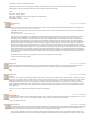
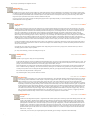
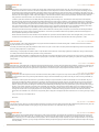
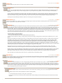
Home Sign Up! Explore Community Submit
All
Art
Craft
Food
Games
Green
Home
Kids
Life
Music
Offbeat
Outdoors
Pets
Photo
Ride
Science
Tech
Dell W5001C 50" plasma fix
by mr12volt on April 8, 2009
Table of Contents
License: Attribution Non-commercial No Derivative Works (by-nc-nd) . . . . . . . . . . . . . . . . . . . . . . . . . . . . . . . . . . . . . . . . . . . . . . . . . . . . . . . . . . . . . . . . . . . . . .
2
Intro: Dell W5001C 50" plasma fix . . . . . . . . . . . . . . . . . . . . . . . . . . . . . . . . . . . . . . . . . . . . . . . . . . . . . . . . . . . . . . . . . . . . . . . . . . . . . . . . . . . . . . . . . . . . . . . .
2
step 1: Symptoms . . . . . . . . . . . . . . . . . . . . . . . . . . . . . . . . . . . . . . . . . . . . . . . . . . . . . . . . . . . . . . . . . . . . . . . . . . . . . . . . . . . . . . . . . . . . . . . . . . . . . . . . . . . .
2
step 2: Teardown . . . . . . . . . . . . . . . . . . . . . . . . . . . . . . . . . . . . . . . . . . . . . . . . . . . . . . . . . . . . . . . . . . . . . . . . . . . . . . . . . . . . . . . . . . . . . . . . . . . . . . . . . . . . .
3
step 3: Testing the Power Supply . . . . . . . . . . . . . . . . . . . . . . . . . . . . . . . . . . . . . . . . . . . . . . . . . . . . . . . . . . . . . . . . . . . . . . . . . . . . . . . . . . . . . . . . . . . . . . . . .
4
step 4: Debugging on the Bench . . . . . . . . . . . . . . . . . . . . . . . . . . . . . . . . . . . . . . . . . . . . . . . . . . . . . . . . . . . . . . . . . . . . . . . . . . . . . . . . . . . . . . . . . . . . . . . . .
7
step 5: Replacing the controller chip . . . . . . . . . . . . . . . . . . . . . . . . . . . . . . . . . . . . . . . . . . . . . . . . . . . . . . . . . . . . . . . . . . . . . . . . . . . . . . . . . . . . . . . . . . . . . . .
9
step 6: Conclusion . . . . . . . . . . . . . . . . . . . . . . . . . . . . . . . . . . . . . . . . . . . . . . . . . . . . . . . . . . . . . . . . . . . . . . . . . . . . . . . . . . . . . . . . . . . . . . . . . . . . . . . . . . . . 11
Related Instructables . . . . . . . . . . . . . . . . . . . . . . . . . . . . . . . . . . . . . . . . . . . . . . . . . . . . . . . . . . . . . . . . . . . . . . . . . . . . . . . . . . . . . . . . . . . . . . . . . . . . . . . . . . . 11
Advertisements . . . . . . . . . . . . . . . . . . . . . . . . . . . . . . . . . . . . . . . . . . . . . . . . . . . . . . . . . . . . . . . . . . . . . . . . . . . . . . . . . . . . . . . . . . . . . . . . . . . . . . . . . . . . . . . 12
Comments . . . . . . . . . . . . . . . . . . . . . . . . . . . . . . . . . . . . . . . . . . . . . . . . . . . . . . . . . . . . . . . . . . . . . . . . . . . . . . . . . . . . . . . . . . . . . . . . . . . . . . . . . . . . . . . . . . . 12
http://www.instructables.com/id/Dell-W5001C-50quot-plasma-fix/
License: Attribution Non-commercial No Derivative Works (by-nc-nd)
Intro: Dell W5001C 50" plasma fix
My buddy's Dell 50" W5001C plasma television conked out one day so I set out trying to fix it. The TV is about 4 years old, and it is out of warranty. Even the three year
extended warranty that was offered for $1000 at the time of purchase would have done no good. (Remember when TV's used to last 20 years?) With no recourse for
repair through official channels, what is one to do?
"So what are my options?"
1.Fix it at a TV repair shop
Calls to television repair shops produced a range of estimates, i.e. $300 for an on-site consultation and no guarantee of repair. Shipping or transporting the TV to a repair
shop could could add insult to injury as it is quite large and might be damaged even further during shipping.
2.Buy a new TV
With new plasma TVs costing about $1000+ for a similar model, it's a tough call between getting the old one fixed or just purchasing a new one. If repairs are more than
$500, you'd be better off just chucking the old one and buying new. Since the Dell wasn't smoking or on fire and looked like it was still in very good condition, throwing it
away seemed like a waste.
3.Take it apart
While my buddy contemplated what he wanted to do (see options 1 and 2 above), I resolved to just take the dang thing apart to see what I could see. I'm fairly electronics
savvy and I love taking things apart, so this was an opportunity not to be missed.
The Bottom Line
Long story short, a $1.09 part took down a $4000 television.
Disclaimer:
The information contained herein is only a journal of my experiences. It is not meant as a tutorial for someone else to fix their own TV. If you use it as such, you do so at
your own risk. Don't blame me if you destroy your TV or get hurt in the process. With that said, please continue reading....
step 1: Symptoms
1. Blank screen
2. TV still powers up, blue led lights up, and relays click at turn on
3. Sound still works
4. Picture may come back for hours at a time but not reliably
5. Picture may appear for a split second when turning off.
How it happened
It all started one day when I went to turn on the TV and, while the power LED lit up and the power relays clicked as usual, the screen was blank. I thought it was on the
wrong input so I used the controller to switch inputs but the on-screen menu would not show up either. The sound, however, was working so it was definitely on the right
input already. I left the TV on for a while and after a couple minutes, the picture magically appeared! Great, it just needed to warm up I thought. After being left on for a
couple of hours however, the screen went dark again. The TV was basically unusable because turning on the TV would usually result in just a dark, blank screen. Since
the sound continued to work, I suspected something to do with the power supplied to the plasma screen proper.
http://www.instructables.com/id/Dell-W5001C-50quot-plasma-fix/
Image Notes
1. Dell W5001C 50" plasma
step 2: Teardown
To access the power supply, one must remove the sheet metal backing to the television. This is quite easy and only requires a T20 torx screwdriver and a common
philips screwdriver. There are many torx screws around the periphery, four large philips mounting screws, and a couple smaller philips screws. Once all screws are
removed, the sheetmetal backing can be pried off the TV (in fact, it may fall right off after the last screw is undone so watch out!) It helps to have a friend at this point
because handling the large back piece can be a bit unwieldy with one person..
Image Notes
1. Torx screws
2. Torx screws
3. Small philips screws
4. More torx screws
5. More torx screws
http://www.instructables.com/id/Dell-W5001C-50quot-plasma-fix/
Image Notes
1. This is what is under the sheet metal backing.
Image Notes
1. Power supply
2. Input board with lots of analog and digital electronics.
3. Plasma drive electronics (mostly covered by heatsinks.)
Image Notes
1. Power supply removed.
2. Power supply in a conductive bag.
3. Grounded metal frame.
step 3: Testing the Power Supply
Static Electricity Warning
Some components on the power supply are CMOS integrated circuits and are therefore sensitive to static electricity. Before touching the circuit board, I make sure the TV
is unplugged. Then, I touch a piece of metal on the back of the TV that is grounded, i.e. part of the metal frame or one of the mounting screws or mounting posts of the
power supply board. This will dissipate any stored static electricity by the body and discharge it to ground. CAREFUL!!! This should only be done with the TV turned off
and NOT plugged in. Otherwise, one might touch something with HIGH VOLTAGE and receive an electrical shock. In particular, stay away from the large heat sinks with
the yellow stickers on them indicating high voltage.
Overview
The power supply is the large circuit board in the middle of the TV. It has many transformers, large capacitors, and a couple IC's. There are eight connectors attaching
the power supply to the other circuit boards on the TV. Looking closer, one can see that the power supply(Model#:PSPF651B01A) is manufactured by Samsung, as is the
plasma screen itself. The supply provides about ten different voltages; 190V, -180V, 60V, etc for the plasma screen as well as 3.3V, 5V, and 12V for the logic and digital
electronics.
The power supply circuit board contains a wealth of information including its part number and a table of the different voltages it produces along their signal names(Va,
Vscan, Vstb, etc). Test points for all these voltages exist on the left side of the board(looking at the power supply as it is mounted to the back of the television).
How to test
I used a multimeter to probe the voltages at the testpoints with the TV turned on. BE CAREFUL!!!! This is of course highly dangerous as HIGH VOLTAGES occur on the
power supply and the TV was not meant to be run with the back off. Touching certain points on the power supply while it is powered can KILL YOU!!!! To be safe, don't
touch ANYTHING inside the TV whilst it is plugged in. In fact, if you do not know what you are doing, just stop here. No point killing yourself over a stupid TV.
If you dare....
The RTN node (seen on the silkscreen at the top left connector(and others) ) is basically the common grounding point and is connected to Earth ground, the shiny metal
backing of the plasma screen, and all the metal mounting pegs that the power supply is mounted to. The black or negative lead of your multimeter should be attached to
this point. I just stuck the black probe into one of the mounting studs and let it hang there (out of the way) so I could probe using the other(red) lead of the multimeter with
one hand.
Start off with the TV unplugged and turned off. Attach the negative or black lead of the multimeter to any mounting stud near the power supply board. Now plug in the TV
and make sure nothing explodes. Now turn on the TV with the remote control and again make sure nothing explodes. Is the screen blank? If so, good. You'll be able to
probe the test points on the power supply to determine which voltage is not being produced. In my case, it was Va which is supposed to be 60V. Make sure to make a
good contact between the testpoint and the multimeter probe. If the contact is poor, the voltage readout may look as though it is fluctuating between the spec'd voltage
and some lower voltage. For example, if the spec'd voltage is 180v, not pressing hard enough to connect the probe and the testpoint may result in a readout that wanders
between 180v and 50v.
If all the voltages are being supplied and withing spec (as shown on the power supply's silkscreened voltage table shown in the fourth picture below), your power supply
is most likely functioning correctly. Your problem may lie in a different area. Numerous people have mentioned a problem with their Y-Buffer, the circuit boards flanking
the left and right sides of the plasma screen. Specifically, whitby905 (see the comments section) has found that the lower left Y-Buffer board was contacting the metal
plasma screen backing and had shorted out. If your power supply checks out, look and smell for any indication that any of the Y-Buffers have shorted to the case. You
may have to remove them and look on the back for shorted solder points. I don't have any pictures of this situation besides the one from whitby905 in the comments
section.
My problem was with the Va voltage of the power supply so I will continue discussing it in the next section "Debugging on the Bench."
http://www.instructables.com/id/Dell-W5001C-50quot-plasma-fix/
Image Notes
1. The power supply board.
2. Va Testpoint
3. Un-isolated high voltage side. Be careful!!
4. Isolated voltages side. Still some high voltages around here so be careful!
Image Notes
1. Nametag
Image Notes
1. Table of node names and voltages on the circuit board.
Image Notes
1. Va Testpoint
Image Notes
1. Grounded metal backing of plasma screen.
http://www.instructables.com/id/Dell-W5001C-50quot-plasma-fix/
2. Metal mounting stud for power supply. Ground yourself on one of these before
touching anything on the power supply to dissipate any static electricity.
Image Notes
1. A multimeter
Image Notes
1. Set one of the multimeter probes into one of the mounting studs before probing
testpoint voltages.
http://www.instructables.com/id/Dell-W5001C-50quot-plasma-fix/
Image Notes
1. Probing Va testpoint.
step 4: Debugging on the Bench
More testing in the lab revealed that the problem was a defective IC, U501 which is a Fairchild Semiconductor part KA3883. I ordered a replacement from digikey, 4973678-ND , which is a STMicroelectronics UC2843B, for $1.09. The original KA3883 is not generally available(discontinued?). UC2843B is higher quality drop-in
replacement.
The proof that the current mode pwm control chip(KA3883) was the source of the problem came from heating just that part with a hot air pencil and watching the Va
voltage go up to 60V then cooling the control chip(KA3883) with a can of compressed air and watching Va go back to zero. The part is defective and for whatever reason
responds to thermal shock. This could have indicated a cold solder joint but, after checking, the solder joints looked fine. Diagnosis: defective KA3883.
Additional Info:
The power supply board is easily detached by removing about ten philips screws and disconnecting the eight connectors.
If you want to test the board on the bench, away from the rest of the TV), you must use an isolation transformer. Plug in one side of the isolation transformer to the wall
then plug in the board to a suicide cord connected to the other side of the transformer. This is so you don't die.
You also need to know how to turn on the board without the remote control, right? This is done by simply connecting pin 'PS-ON' (found on connector CN8007) to
ground(ie the RTN pin). I used a small jumper to short across from PS-ON to RTN. You can just leave the jumper there and use a power strip to turn the whole thing on
and off.
I traced out much of the relevent circuitry to make sure I knew what I was probing and so I could debug the Va circuit. The excellent layout and silkscreen notation on the
Samsung board was very helpful. The Va circuit is mostly contained within the 500's numbered parts, ie U501, C501, R501, etc. If you are going to probe any of these
parts with the board powered you MUST USE AN ISOLATION TRANSFORMER so you don't electrocute yourself or destroy the board, especially if you are using an
oscilloscope or something that is not battery powered.
Image Notes
1. Isolation Transformer
2. Power strip used as a switch to turn board on and off.
3. Suicide cord
Image Notes
1. AC input header
Image Notes
1. Safe
2. Death
3. Suicide cord
Image Notes
1. Testpoints
2. Va Testpoint: This was the one that was not working.
3. Test Connections for Va. Wires are soldered to the vacant vias and clip leads
are attached to the wires.
http://www.instructables.com/id/Dell-W5001C-50quot-plasma-fix/
Image Notes
1. 750ohm 25W resistor as a load used during testing of Va.
Image Notes
1. Jumper across RTN and PS-ON to make board turn on.
2. More testpoints.
Image Notes
1. Airpencil, usually used for surface mount soldering.
http://www.instructables.com/id/Dell-W5001C-50quot-plasma-fix/
step 5: Replacing the controller chip
The first thing you need to do is get rid of the defective part, U501.
One method is to remove the chip by getting rid of the solder holding it in place. Either use a solder sucker desoldering station (if you have access to one) or solder wick
to remove the solder then pull the whole chip out. Careful with the solder wick. If you heat up a pad too much, you WILL lift a trace, effectively destroying the board. It's
very hard so get it right with the solder wick.
I used the desoldering station to clear the lead holes. Then, I attached the SIP sockets to the new part, placed it into position, tacked the part by soldering pins 1 and 8 to
hold it into place, and then soldered the rest of the pins. The reason for using the SIP sockets and not a normal 8 pin socket is because the width of the holes is unusual.
DIP parts are normally 300mils wide however the width used on this board for the DIP parts is about 340mils (when I say width I mean from say the center of the hole of
pin 1 to the center of the hole of pin 8.) A normal 8 pin DIP socket will not fit, hence using two strips of SIPs. However, mhra08a has used Radio Shack 8-Pin IC Retention
Contact ($0.48 Model: 276-1995 Catalog #: 276-1995) with success.
Better Method(if you don't have a desoldering station)
I suggest just cutting the leads off the old part and soldering in a strip of 0.100" pitch SIP sockets to the old leads that are left sticking up out of the board, ie a strip of 4 on
one side and another strip of 4 on the other. Try digikey ED7064 . This way, there is no desoldering and you'll have a socket there to make it easier if you have to replace
the part again. You must be very careful when using a small side cutter to snip the leads from the chip (this is the simplest way to do it however). The action of the cutter
will push the lead and the chip to the side, putting lots of stress on the hole that the lead is soldered into. Again, damage of the circuit board could result.
Also note jackohound's method he describes in the comments section:
"As I didn't have a desoldering station, or a small enough side cutter snip the U501 leads, to I used a Dremel tool with a very small cutting disk to carefully cut teach of the
leads from the old chip. This required a steady hand, but it avoided putting any stress on the board. I removed the old chip body and used a handheld spring-loaded
desolderer to remove solder from each of the holes."
After the chip body is removed, you can solder the SIP sockets to them. Watch out because when you touch the soldering iron to the lead you will also melt the solder in
the lead hole and the lead may move, fall through, or cock to one side. You might try first soldering a solid wire to all four leads on one side to keep them in position as
you solder the SIP sockets.
Make sure you install the new part with the right orientation! Otherwise you'll probably blow a fuse on the board(best case) and may take out some other parts as well.
Image Notes
1. Current mode PWM controller area for Va circuit, high voltage un-isolated side.
2. Va transformer provides isolation.
3. Isolated side of Va circuit.
4. Va power MOSFET and current sense resistor.
5. 120V input.
http://www.instructables.com/id/Dell-W5001C-50quot-plasma-fix/
Image Notes
1. U501 is Fairchild KA3883 current mode pwm switch mode power supply
controller.
2. Jellybean opamp
Image Notes
1. Defective part.
Image Notes
1. Desoldering station.
2. Regular soldering iron.
3. Soldering iron with a bore hole down the center through which solder can be
sucked.
4. Air filter so solder does not get sucked into the pump.
Image Notes
1. Desoldering wick (braided copper with flux)
http://www.instructables.com/id/Dell-W5001C-50quot-plasma-fix/
Image Notes
1. Holes cleared of solder using the solder sucking desoldering station and a touch
of solder wick.
2. Still a little bit of solder in this one.
Image Notes
1. SIP sockets (row of 4) attached to each side of the new part.
Image Notes
1. Finished repair job.
Image Notes
1. Reverse side of finished solder job.
step 6: Conclusion
Now install the board back onto the TV, and connect only the smaller connectors to test the board. Plug in the power to the TV and turn it on with the remote. Probe the
Va testpoint with a multimeter to see if it is between 55 and 75 volts. If so, the repair worked! Turn off the TV, unplug it, and install the other connectors to the power
supply board. Install the backing onto the TV and you're done. Congratulations! Your roommates now think you're a genius.
Related Instructables
How to fix the
power cord to
my Dell laptop
that time by
uncoolpizza
Dis-assembly
and repair of a
Dell E173FPf
monitor by cclla
Fixing a minor
design fault
with the Dell
Dimension 4300
- 5000 series. by
killerjackalope
FREE 17" LCD
Monitor - How
to do it? by
thearchitect
http://www.instructables.com/id/Dell-W5001C-50quot-plasma-fix/
How to fix your
Sharp 56DR650
with color wheel
issues by
adcurtin
A (very) Simple
LCD Backlight
Fix by bchafy
TV set cutout by
caitlinsdad
HOW TO FIX
YOUR TV by
plasticpool
Advertisements
Comments
42 comments Add Comment
jwoyshnar says:
Sep 18, 2009. 7:18 PM REPLY
Hello all, wondering if someone can help me out there. I tested the test points and came up with some odd numbers. Va was 132, the 5 volt was 10 and the
12v was 24. All other voltages were absent. Any help with this on where to turn next would be greatly appreciated.
thanks
mr12volt says:
Sep 22, 2009. 6:22 AM REPLY
jwoyshnar,
My first inclination is to suspect your measurement device (multimeter,voltmeter?). The reason is because the three voltages you mention are exactly
twice their expected value. That seems somewhat unlikely. The 5v and 12v outputs likely use some kind of linear regulator stage. Doubling the input
voltage to the regulators would not result in doubling the output voltage, it would result in the same output but with much increased dissipation at the
regulator. Also the output of Va should not affect and is not dependent on the 5 or 12v supplies. Have you measured other voltages and are they reading
correctly?
-mr12volt
jswmc7 says:
Nov 18, 2009. 8:12 AM REPLY
Mr12volt,
Thanks for your time to post this information. I have 2 of these dell 50" plasmas. I have been lucky not to suffer from power on issues described
here. I do have a picture issue. My 50" dell suffers from flashing green, red ,and blue pixels at cold start which disappear after aprox. 15 minutes.
A couple years ago I causiosly checked the voltages and they were in spec. I adjusted the little blue things( what are they called?) and it
helped alot. The board just to the left of the power supply(what is that one?) has 2 white adjustments and that helped the most.
Is it improper voltage that causes the flashing pixel issue and what are the blue adjustments called? Do you have any suggestions as to what i can
try?
Again thank you!!
jackohound says:
Aug 28, 2009. 6:30 PM REPLY
I obtained the replacement parts, replaced the U501 chip, and now TV is working good as new.
As I didn't have a desoldering station, or a small enough side cutter snip the U501 leads, to I used a Dremel tool with a very small cutting disk to carefully cut
teach of the leads from the old chip. This required a steady hand, but it avoided putting any stress on the board. I removed the old chip body and used a
handheld spring-loaded desolderer to remove solder from each of the holes. I installed two strips of SIP sockets as mr12volt recommended.
jackohound says:
Aug 27, 2009. 8:54 AM REPLY
mr12volt,
Thanks for the effort and time you spent documenting this instructable. In the last few days, my Dell W5001C started displaying an intermittant black screen.
When the set is powered on from cold, the LED lights, and the TV clicks, and the audio works, but the screen doesn't come on. After the TV runs for 20
minutes or so and warms up, the video will come on. At the moment, once the video comes, on the TV seems to be stable and reliable at least for several
hours.
Using your instructable, i've confirmed the same symptoms you were seeing. The Va is at 0.5 volts while the screen is black and goes to 58 volts when the
video comes on. All the other voltages look reasonable and stable.
With the TV powered on and in the "black screen state", I used a hair blow-dryer aimed at U501. I heat the U501 area for just a few seconds and that causes
the video to appear. Once the area has been heated and the video is working, I can then use freeze spray on U501, and cause the "black video" to reappear.
I will order up the replacement part from DigiKey and attempt the replacement of U501. I'll report back on my experience.
I am in NW boston area. Assuming you are local and you might have some extras of the replacement UC2843B chips, and migh be willing to sell me one, i'd
be extremely happy to do that.
Thanks again for this instructable.
sheya says:
Aug 24, 2009. 4:44 PM REPLY
I thought I would share my experience with my repair, since someone else might find it useful.
Curious as to how you found a replacement for the KA3883. Is there a database online somewhere that offers equivalent part numbers? It would be great to
be able to upgrade parts as they are replaced.
I have discovered a seemingly strange problem with my W5001C. When I measure the power supply inside the television, completely hooked up, Vsc, Vs,
Vset, and Ve are all way out of spec, some measuring less than a volt. Va, 12volts, and 3volts are fine. The 5 volt supply is around 3 volts. If I unhook the
cable at the bottom of the power supply, the one that goes into the board underneath the board with the connections, all of the voltages are in spec except
for the 5 volt supply. I reheated all the solder joints in line with the 5 volt supply and still have the same problem. I suspect that if the 5 volt ug isn't in spec,
then something on that daughter board shuts down power. If I measure Vset after I unplug the daughter board, I can watch the power sag until it gets to
millivolts (the caps discharging).
So, now I have to find replacements for the regulators in line with the 5 volt supply. It looks like I might have to desolder the one right after the transformer
just to see the part number because I can't see it in place.
I had thought I needed to replace all the ICs on the board, but it seems that the 5 volt supply is the culprit. I gathered all the part numbers and sources for the
http://www.instructables.com/id/Dell-W5001C-50quot-plasma-fix/
IC's already, so I thought I would share them below.
I'll post the part numbers for the 5 volt supply when I find them, and post progress on my repair in case someone else has a similar issue.
Please feel free to correct any errors that I have made. Thank you again for making this instrucable.
Aaron.
U202, U662 - KA393A - Mouser
U403, U551 - KA358A - Mouser
U501, U661 - UC2843BN - Mouser (same as digikey 497-3678 listed above)
U402- IR2019 - Digikey
DIP-8 Sockets- 4-1571551-2 - Mouser
mr12volt says:
Aug 25, 2009. 7:06 AM REPLY
sheya,
Thanks for adding to the discussion. I'd like to reply first with a correction. I believe U402 is actually International Rectifier IR2109, a half bridge driver.
http://www.irf.com/product-info/datasheets/data/ir2109.pdf
Additionally, I remember the board having a 16 pin DIP, which you did not list, and I think it is a Fairchild ML4824, a power factor correction(PFC) and
PWM controller combo.
http://www.fairchildsemi.com/ds/ML/ML4824-2.pdf
Now I have one or two suggestions. Try unplugging all the cables to the power supply except the AC input. Use a shunt to bridge the turn-on pins as I
have shown in step 4, debugging on the bench. Make sure to have the set unplugged from AC when you bridge the turn-on pins or it will turn on
immediately. Plug in the power cord to the wall outlet, the TV will turn on, now test all voltages. They should all be within spec. This test isolates the
power supply from all the other boards. It sounded like you were considering a scenario where the 5V regulator was defunct and was not supplying
enough voltage to one of the logic boards which would send a signal to the power supply to shut down some of its outputs. The above test will prove or
disprove that hypothesis. There still may be a shutdown on the power supply if 5V is undervoltage, but I find it somewhat unlikely. The IR2109 has a
shutdown pin but that pin is fed by the ML4824 through one of the KA358 dual op-amps which compares the Vref from the ML4824 to Vfb. That is just
part of the normal voltage regulation circuit as far as I can tell. Looking at my sketchy notes from this project, I believe ML4824 produces a 17volt rail. It
powers U501 for example. When tracing the circuit, I only saw that U501 was producing one output, Vs. By this I mean that its output was only connected
to one transistor and then to one transformer. Since there are numerous other voltages on this board, I can only imagine that they are all regulated by
U661off of some common transformer with multiple windings. Somewhat confusing though considering how many transformers there are on this board?
How come there are 10(roughly) transformers and two regulator chips? This is why I think U661 MUST be controlling most of the other voltages. How
else could it work?
Please shed some light on this for us if you happen to trace the circuit and can tell us the exact topology.
Hope you can get your (free) TV working.
-mr12volt
sheya says:
Aug 21, 2009. 11:53 PM REPLY
I didn't see the comments below before I wrote my question, I think that I either completely missed them, or all of the comments don't appear on all the
pages in the instructable. You have already answered my questions below. Thank you again for sharing your knowledge and experience.
Best,
Aaron.
sheya says:
Aug 21, 2009. 11:54 AM REPLY
mr12volt,
Thank you so much for the time you spent putting this instructable together. Yesterday I found a Dell W5001C curbed for the trash. I got it home in one piece
(not so easy). The LED lights, and the TV clicks when it is turned on, but the screen doesn't come on. I measured the power supply, and VSC and VSET are
measuring in the millivolts. Va is 60.57, Vs is 8.5 volts, the 12 volt supply is fine, and the 5volt supply is 3 volts. I don't have a hot air gun or isolation
transformer to test the circuit as you did, so I am wondering if you happen to have discovered which parts I could replace in the VSC/VSET circuit in the
hopes of replacing the defective parts. I have checked the fuses, and they are all good, but beyond that, I am not sure that I have the equipment to test the
board. I realize that I could be hunting in vain, replacing parts in the hopes I find the correct one. My hope is that you have some suggestions as to what I
should replace first.
Thank you for your time, I appreciate your sharing your experience and knowledge.
Aaron.
whitby905 says:
Jul 6, 2009. 6:31 PM REPLY
I'm having the same problem as manuts, voltage problem isolated to Vscan. I measure a constant fluctuation which jumps anywhere between -50 to -175 (or
so) somewhat like -50, -166, -75, -175, -80....continuous in fraction of seconds. NO screen change at any time, just black.
Kudos to the brilliant people here!
mr12volt says:
Jul 6, 2009. 11:16 PM REPLY
It sounds like the controller for the Vscan voltage has become unstable or is not being supplied with enough voltage to maintain regulation. Unfortunately
I am not in possession of this TV anymore so I am of limited help. Is there anyone here with a similar Vscan problem located near the Boston area? I
wouldn't mind doing a house call to get to the bottom of this one. If so, message me via Instructables.
Also, can anyone shed light on the mentions I've heard of certain problems being fixed by replacing some of the electrolytic capacitors? Which caps?
What specifics problems has that solve? An unstable voltage regulator chip could be affected by not enough capacitance on the input or output. This is
http://www.instructables.com/id/Dell-W5001C-50quot-plasma-fix/
why I bring it up. Electrolytics do degrade over time.
whitby905 says:
Jul 7, 2009. 9:17 AM REPLY
Thanks for your reply mr12volt.
In regards to the e-caps I can tell you that audibly (very faint) there appears to be some relationship to the fluctuation of the voltage...meaning that I
can hear the cap altering buzzing with the voltage changes. I also found that if I press the input button on the remote I can hear the buzzing increase
in volume (amplitude) until it defaults back to whatever input is active (after about 5-6 seconds) then back to the previous buzzing. These are the
large case caps in pair closest to the Vscan circuit flow, before the test point..
I'm going to source new e-caps to change out although they appear to be in good shape visually. If I can find someone to check the e-caps I can
further determine if that is my problem.
mr12volt says:
Jul 22, 2009. 6:50 AM REPLY
whitby905,
Are you sure the buzzing is coming from the capacitors? It is more likely that the buzzing is actually coming from the transformers. The current
pulsing through the transformers produces a changing magnetic field causing an alternating constriction in the coils of the transformer windings.
The magneto-mechanical constriction and relaxation produces the buzzing sound, a useful diagnostic tool. One is able to audibly tell if there is
some sort of intermittency in the transformer circuit by listening for these audible changes. My method of attack was to find the control IC
(hint:look for the DIP parts) and poke its pins with my multimeter while listening for audible changes. This is VERY risky however (and slightly
disconcerting when the buzzing jumps in volume or frequency). If your hand slips, the multimeter probe tips can short things out and cause more
damage. I like to set the probes in position with the TV power off, then turn the power on and read the voltage off the meter. Less chance of
disaster that way. Look up the datasheet for the control IC and compare the voltages you recorded for each pin to what they should be according
to the datasheet. This takes a bit more advanced knowledge, however, feel free to post your results on this forum and we'll try to help.
I wouldn't immediately suspect the electrolytics as the cause for any problems you are having unless there is some other evidence that points to
their failure. Pressing the input button on most tv's causes some changes in the audible buzzing so I wouldn't necessarily label that as cause for
concern or even unusual.
It sounds like you're doing some excellent investigative work. Keep poking around. The more you play with it, the better chance you have of
stumbling upon the solution. Keep us updated.
p.s. Sorry for the late reply, I've been on holiday since July 7th.
whitby905 says:
Jul 29, 2009. 8:59 AM REPLY
mr12volt,
Thanks for your reply and I hope you had a good holiday.
It seems like this project is evolving or possibly devolving depending how you look at it. Upon further testing the voltages are ALL to spec...the
earlier Vscan measurement may have been incorrect due to the pressure applied at the test point from the probe??? It is within spec and not
jumping. I have found the data sheets for the IC's and am going to check values, but upon
further investigation I've found that the controll board (directly behind the input board) there is 2 green LED's near top right of board that the
left is on solid and the right is blinking. I don't know if that has any meaning or is an indication to my problem but I'm trying to find that out.
Currently when powered on the set still gives the slight audible relay click and (your right) transformer buzzing, power indicator LED (blue) on,
but no action from the pannel itself...nobody home.
Any further thoughts?? I'll let you know about the IC check.
mr12volt says:
Jul 29, 2009. 10:31 PM REPLY
When the TV is off but plugged in, one of the green LED's should be lit. I don't remember what the other LED does when the TV is turned
on but blinking seems reasonable. If all the outputs on the power supply are within spec, the problem may not be the power supply. Don't
bother checking any of the IC's on the power supply if this is the case. If the output voltages are good, the IC's are doing what they
should. (You may want to triple check the voltage testpoints however, just to be sure.) The TV has plenty of other electronics to go wrong.
Specifically I've heard many people needing a new Y-Sustain board. Unfortunately I don't know exactly what this is (again, my experience
is limited to this one power supply defect.) Basically, if it's not the power supply, it is either the input board below the power supply or one
of the plasma drive boards which are flanking the power supply on either side of the TV, or the plasma screen itself. These are all much
more difficult to work on than the power supply. They are more highly integrated boards. Make sure the power supply is okay, and if it is,
then you may have to bite the bullet and either take it to a TV repair shop or buy a new TV. If you buy a new TV, I suggest you sell the
working parts for this Dell on eBay. From the sound of it there are plenty of people who could use them.
whitby905 says:
Jul 30, 2009. 7:06 AM REPLY
mr12volt
I believe we have diagnosed the patient…it appears that the Y-Buffer (lower) which is the long 2 piece PCB flanking the left side of the
screen is the problem. I decided to look deeper since the voltages on the power section registered within spec. After a deep visual
inspection with magnification and good lighting that yielded no visible results, I started to smell around (using a paper towel roll that
just happened to be within reach, so as not to bump my nose into any high voltage parts), I noticed a distinct electrical odor from the
left-bottom side. I removed the Y-Buffer and looked to the back of the PCB and voila… there was a short in the solder pattern. It was
possibly caused by the heat generated in that region that made the board shift to touch the aluminum case, although there are white
plastic standoffs to prevent that, there is not one near the problem location??? So I think that I’ll sign the donor card and allow other
Dell’s to live…e-bay it is.
I must thank you mr12volt for your original posting which ultimately got me through to experience this small triumph.
http://www.instructables.com/id/Dell-W5001C-50quot-plasma-fix/
chuckbox says:
Aug 5, 2009. 5:21 PM REPLY
What a great set of instructions. I have followed these to the same discovery on my tv.. My lower Y-board has the same burned
area as above. Were you able to buy another Y-board or did you scrap the tv? Any ideas
mr12volt says:
Aug 6, 2009. 9:49 AM REPLY
whitby905 and chuckbox,
Do either of you have your dead Y-Buffer? I would like to photograph and disassemble it, and perhaps publish some detailed
information on this second failure mode.
whitby905 says:
Aug 6, 2009. 10:10 AM REPLY
I still have it. Let me know what you want and I'll do my best.
whitby905 says:
Aug 6, 2009. 6:23 AM REPLY
Screen is gone but not before I removed the tuner, controller and power assemblies. I'll ebay it at some point soon. Good work
everyone. Great site here.
mhra08a says:
Jul 25, 2009. 8:09 AM REPLY
This fix worked exactly as advertised. Thanks so much. The only thing I did different was I used a Radio Shack 8-Pin IC Retention Contact ($0.48 Model:
276-1995 Catalog #: 276-1995) that was a little easier to install than the two banks of single pins. The pins spread slightly on the IC socket which covers the
few mm difference between the socket and the holes on the board. Hard to believe such a cheap component can wipe out an expensive TV. Thanks again,
mr12volt says:
Jul 25, 2009. 10:39 AM REPLY
Bravo! Did you use a solder sucker, solder braid, or just cut pins to remove the old part?
Did your set fail recently or have you been looking for a way to fix it for a while?
Was it easy for you to find this instructable? Please rate it if you have time.
Glad to help,
-mr12volt
mhra08a says:
Jul 26, 2009. 7:33 AM REPLY
I am not sure where to rate this as I don't see any kind of rating tool. On a a scale of 1 to 10 I'd rate it a 10. I am a pretty inquisitive do-it-yourselfer
but I likely would not have attempted this had I not seen such a detailed process depicted. I work in the IT industry and have have dozens of my
friends check this page out. The level of detail is great and well beyond what you would get from any commercial vendor (certainly beats Dell
support).
mhra08a says:
Jul 26, 2009. 7:24 AM REPLY
I used a combination of methods to remove the old one. I was going to use the cut the pins method but my miniature dikes were not small enough to
cut the middle pins. I could only get the end ones. I was trying to avoid removing the board. So then I decided to remove the board and used a
soldering sucker to clear out the holes. As careful as I was, I still damaged one of the traces but not significantly enough that I could solder the pin of
the socket. I was actually hoping I could use this as an excuse to get a new LCD or Plasma. LOL.
manuts says:
Jun 7, 2009. 10:18 AM REPLY
Hello. I found your article very informative and helpfull. However the problem on my plasma is the Vscan. It should measure -190v but the actual
measurement fluctuates between -180v and goes down to about -50v. This seems to be the problem, Do you know which components on the psu control the
vscan? I have the service manual for the tv but doesnt provide the schematic of the psu. Any help would be appreciated. thanks
http://www.instructables.com/id/Dell-W5001C-50quot-plasma-fix/
mr12volt says:
Jun 17, 2009. 2:55 PM REPLY
manuts,
I didn't trace out the Vscan circuit so I couldn't say exactly which components are involved in that circuit. As I have said in the other comments, you
should look at the traces on the board to see which components the Vscan testpoint is connected to. Be aware of the component numbering. For this
circuit board, all the components numbered in the 500's(or 400's or 200's or whatever the Vscan circuit is) more or less belong to the same circuit. The
circuits on this board have their outputs on the left (looking at it as it's mounted to the back of the tv) and run roughly horizontally towards the right side of
the board. The Vscan supply is a switch mode power supply so it has the usual transformer, diode, mosfet, opto-isolator, and control chip. There are
many of these on this board, however, so to find which ones you'll have to trace out the circuit.
It is hard to guess what would be the most likely defective component(s) without knowing more. The switch and control chip are the usual suspects
because the switch experiences lots of electrical and thermal stress and the control chip is a complex IC. Also possible is a defect in the circuit board
such as a cold solder joint. A cold solder joint is where a lead of a component is not soldered at a high enough temperature and results in a bad electrical
connection which can respond to physical shock and thermal stress. A solder joint may also be broken or cracked because the tv was dropped or hit.
Look on the front and back of the board along the defective circuit to see any components that look like they are not soldered effectively or the solder
connection is cracked or broken. A cold solder joint looks dull and/or bulging unlike the smooth and shiny normal solder joints.
Others have said that the electrolytic capacitors go bad on these boards and eventually need to be replaced. This is because the electrolyte inside the
capacitors dries out over time and they lose their capacitance. I don't have any information related to the symptoms produced when this happens or
which capacitors specifically are more vulnerable.
What is the exact nature of the Vscan fluctuation. Does it fluctuate over a period of seconds? Minutes? Hours? Does it happen when you turn the tv on or
off? After the tv has warmed up? Is your screen just blank all the time? Or does the picture come back when the Vscan goes back to -180v?
mbsimonds says:
Jun 4, 2009. 11:06 AM REPLY
I'm not an engineer. I like to tinker with televisions in my spare time and sometimes i'm successful at fixing them. I donate most of them to local schools. I
hope this one works out, it's a really nice TV.
It's actually too bad that many times the problems in these sets is a $1-2 part. I have found for the most part that the capacitors go bad on the power boards
and can be easily replaced for a couple bucks.
Unfortunately, TV repair people are hesitant to take on a job with these tv's because they cannot always guarantee it will be fixed. Having a customers pay
for a $300 power board and then still having a broken TV isn't good business.
I think it's tough finding information on repairing these sets is because once someone has figured out how to fix there own tv they move on and don't bother
posting the info. On top of that it's not good business for repair people to reveal there dirty little secrets about replacing $1-2 parts and charging hundreds for
a simple repair.
mbsimonds says:
Jun 3, 2009. 8:10 PM REPLY
Good Stuff man. I really appreciate you taking the time to share this with people. I have the 46" model with the same problem. I followed your instructions up
to the point of heating up the U501 part. When the part was heated up the television worked. I also tested the voltage of Va and it was up near 70v. Once i
removed the heat the tv slowly went out again after a couple minutes. I've ordered the part and hopefully this will resolve the issue also.
mr12volt says:
Jun 3, 2009. 10:57 PM REPLY
Thats great! You're the first person who has contacted me with the same problem. Just glad I can help. Tell me a little about your level of expertise, arre
you an engineer of some sort or just handy with electronics? Did you find the instructable easy to follow? How did you come across my instructable, by
googling?
The reason I wrote this piece was because of my frustration at finding no help or information out there that would help me fix the television. Why isn't
there a site that collects this kind of information so consumers can band together and help each other out? I'd really like to know how many others are
experiencing the same failure. I suspect that one reason there is not more information like this (for free) is because it is quite costly (in man hours) to
produce. I spent quite a few hours tracing the circuit board and understanding the offending circuit. As a grad student, my time isn't worth much (not yet
anyway). I did, however, talk with my professor who quite literally wrote the book on electronics and charges $500 an hour for consulting work (good
thing he has to pay me instead of me paying him). I get a chuckle when I think that if all the people I had to consult with to fix my friend's broken TV were
to charge me it would come out to roughly the price of a new 50" plasma. I realized that not many people have access to the tools and other smart
people that I have available to me, so there was an opportunity there to help quite a few people that were stuck with a bum TV and no good way to rectify
it.
In any case, hope you can complete the fix.
Good Luck
Lez1pyt says:
May 28, 2009. 7:15 PM REPLY
You are right and I truly thank you for this information at least there is someone out there willing to help others My husbands pretty electronic savvy but I was
worried he may electrocute himself So we're going to use your advice and take it to a tv repair after we try to get the part
Thanks
mr12volt says:
May 30, 2009. 9:24 AM REPLY
This fix will not work for EVERY W5001C malfunction so make sure the symptoms your particular set is experiencing are the same as the ones I have
described in the instructable. If they are, you will still need to confirm that it IS the same problem by checking the Va voltage testpoint as I described in
step 3. Obviously if your TV doesn't show the same symptoms, the fix I described may not help. Hopefully I've given enough information for you to make
that determination. I'd hate for you to go through the hassle of obtaining the part and paying an electronics specialist to perform the repair if its not going
to fix the problem!
http://www.instructables.com/id/Dell-W5001C-50quot-plasma-fix/
Lez1pyt says:
May 28, 2009. 10:39 AM REPLY
How can an ordinary lay person do this or can they do this It seems very difficult
mr12volt says:
May 28, 2009. 1:58 PM REPLY
Lez1pyt,
You are correct, this instructable IS written at a fairly high level and is mostly intended for an audience with some electronics and soldering experience.
However, I tried to explain in step 1 that this is simply a journal of my own experience fixing a plasma TV and should certainly not be attempted by
everyone.
The real value in the instructable is the information about the symptoms and diagnosis of one particular failure mechanism. While most people do not
have the experience necessary to diagnose the problem, many will know somebody who has some mechanical ability and soldering skills. My hope is
that, with the information I have given, the owners of these TVs can seek out a friend with the modest experience necessary to perform the fix.
The hard part is not de-soldering the defective component. It's knowing which component is defective.
Solder Sucker says:
Apr 28, 2009. 5:11 PM REPLY
I have the same problem as you. However i checked the Va voltage and got 60 volts and proceeded to other test points and the 190 vsat or set was not
present...any ideas where I could start to look on board?
mr12volt says:
Apr 28, 2009. 9:24 PM REPLY
I would start by following the Vset testpoint to see where it leads in the direction away from the connector. Draw out the relevant circuit as well as you
can by looking at the traces connected to Vset. This takes some time flipping the board over and over as the traces will weave through vias from the front
side of the board to the back. Use the multimeter in the resistance or diode mode (where it beeps if you touch the probes together) to quickly discover
connected paths. Take note of the labels of the components that are attached to the Vset circuit (the Va circuit was in the 500's, i.e. R501, C502, etc.)
This way you won't have to trace through the whole board to know basically which components are related and (most likely) connected. The Vset section
of the power supply will contain the basic components of a switching power supply: tranformer, mosfet switch, current sense resistor, large diode, control
chip. See if you can locate these components. Do any of them look burnt? Do the solder joints all look solid?
Three basic things you should be looking for:
1. Burnt or obviously damaged components.
2. Cold solder joints (solder joints that weren't soldered well during manufacture.)
3. Components that respond to heating or cooling (looking for this requires heating or cooling parts of the board while it is intalled in the tv or on a test
bench.)
Moving from the left(where the testpoint is) to the right, you will probably encounter first some resistors and capacitors, a variable resistor (to adjust the
Vset voltage), opto-coupler, then the transformer, diode, and mosfet. Furthest to the right you will find the control chip for the Vset voltage, possibly
connected to a discrete transistor or two. This is likely somewhere in the middle section of the board. One possibility is that the control chip has a
shutdown pin that is being controlled by some other logic on the power supply board or even off board and is inhibiting normal operation. Take note of
the control chip, download a datasheet for it, study it, and pay special attention to any Enable or shutdown pins. If it has some, you will want to probe
those pins to see their logic level. WATCH OUT! The control chip is on the un-isolated side so is at line voltage with respect to ground. Touching anything
in that area with any part of your body while the TV is even plugged in could give you a nasty shock.
While probing the control chip, especially its Vref and compensation pins, notice any change in sounds that the board is making. Have another
multimeter on the Vset output to see if it magically comes back at some point while probing around. These are all clues as to what is going wrong.
One last caveat, if you have an oscilloscope and are tempted to use it, DO NOT connect the scope probe ground to anything unless you use an isolation
transformer. Battery operated high impedance multimeters are mostly safe to use without damaging the TV or the multimeter (as long as the probe
doesn't slip) but there is still the risk of shock if you touch something at high voltage (take special note of the yellow stickers on the heat sinks.)
Sorry I can't help out more with tracing out the circuit. Our TV is all buttoned up and operating normally.
elperdido says:
Apr 14, 2009. 6:32 AM REPLY
Most TV Servicers are doing a good job coping with the lack of information/communication/training provided by the manufacturers. It's good to see that you
are sharing this information for everyone to see. Also, for those who aren't so tech-savvy, a lot of times you can do simple board swaps and you can find
parts for cheap from places like shopjimmy.com.
mr12volt says:
Apr 14, 2009. 7:23 AM REPLY
Thanks for the tip about shopjimmy.com. One of the aggravating points about this TV is that parts are very scarce. A search on shopjimmy shows two
hits for a similar power supply (for the 42" version), both labeled as out of stock. We searched many other online parts dealers with no luck. Replacing
the whole power supply was my preferred method of repair (cost ~$200) because of its simplicity, but with no parts available, I was left with no choice but
to learn how to fix it myself. I just hope the time spent will save others some hassle and be a warning to NOT buy Dell until they get their act together in
terms of supporting their products with parts and service.
elperdido says:
Apr 15, 2009. 5:48 PM REPLY
Dells are a tough fix: they're in-house circuit boards are NLA, their customer service is lacking, and a lot of the Samsung parts in them are either:
a. different revisions from the same part# pulled from another TV(incompatible)
or
b. out of stock because it was used in so many other TVs at the time.
It's sad to say, but for every circuit board you need, there's at least 100 others looking for the exact same thing, and most of this stuff isn't stocked
anywhere.
http://www.instructables.com/id/Dell-W5001C-50quot-plasma-fix/
Dandeman321 says:
Apr 13, 2009. 8:39 AM REPLY
How did you know to check that chip?
mr12volt says:
Apr 13, 2009. 10:34 AM REPLY
I mentioned in Step 4 that I heated the chip with an air pencil and it caused the voltage to suddenly turn on. I had first noticed that after the whole board
being on for a minute or two, the Va supply would come back to its normal 60volts. It was audible. There would be a slight buzzing when it went from the
off state to the on state. I imagine this was due to the transformer being turned on and off at an audible frequency. So I guessed from this information that
it was possibly heat related.
I also knew roughly which components were involved because most components connected to the Va voltage were labled with a 500's number, ie R501,
C501 for resistor 501 and capacitor 502, etc. The defective component(s) had to be within that circuit, labled in the 500's most likely. Also, without any
visible damage, its not likely that the problem was with the transformer, power mosfet, film resistors, or ceramic capicitors. The only active components in
the circuit was the defective one (KA3883, smps pwm current mode controller) and an opamp(358).
So I focused on those active components, using a heat gun to warm them up and see if anything happened. Sure enough, the voltage turned on when I
hit them with a little heat from the large heat gun(which heated up pretty much everything.) I then used the air pencil to target those two components to
see which one was faulty. Just due to the nature of the failure and from the little knowledge I gained from drawing out the circuit by looking at the board
traces, I could not imagine what else COULD be faulty besides the controller chip.
It boils down to process of elimination and an educated guess.
Dandeman321 says:
Apr 13, 2009. 12:24 PM REPLY
Ahhhh gotcha. I'm in electronic engineering technologies right now, working on my third year, and I love this kind of work. I just wish I was better at it.
I would have opened up the tv and been like "screw it, too many parts." Great instructable by the way. I'll have to be more patient with my future
repairs!
lemonie says:
Apr 13, 2009. 7:16 AM REPLY
Some people still do repair TVs, it's good to see this.Most people dump these things...
Might qualify for Earthjustice United States of Efficiency Contest in consideration of the waste avoided by otherwise replacing the unit early?
L
http://www.instructables.com/id/Dell-W5001C-50quot-plasma-fix/