1
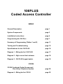
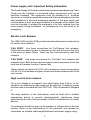
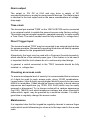
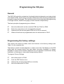
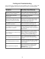
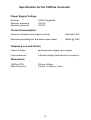
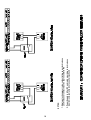
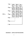
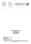
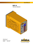
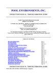
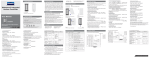
108PLUS
Coded Access Controller
Bell System (Telephones) Ltd
Milton Keynes
CK109
Complete Coded Access System
CS109
Combined Coded Access and
Door Entry Telephone System
PD-022 Issue 1
108PLUS
Coded Access Controller
INDEX
General Description
page 1
System Components
page 3
Installation Instructions
page 4
Programming the 108 Plus
page 7
Summary of Programming (Tables 1 and 2)
page 11
Testing and Troubleshooting
page 12
Specifications for the 108 PLUS
page 16
Diagram 1 - Wiring for the 108 PLUS
page 17
Diagram 2 - High current lock releases
page 18
Diagram 3 - 108 PLUS keypad matrix
page 19
CS109
CS109 Combined Coded Access and
Door Entry Telephone System
page 20
Diagram 4 - Wiring for the CS109
page 22
General Description
The 108Plus Coded Access Controller is a high quality, versatile security
product, controlling access to one or two doors by means of a keypad and
an electric lock release mechanism.
Basic Operation
The 108Plus Controller may be programmed, with two unique access
codes for each entrance. During operation, persons authorised to gain
access, must enter one of these codes on a keypad. If the code is correctly
entered, an electric lock release will activate, for a preset duration,
allowing free passage through the door. Repeated false entries on the
keypad can be programmed to activate an audible alarm, for a further
preset period, during which time, operation of the door release is inhibited.
Other Features:
!
Two door operation
The Model 108PLUS is effectively two access controllers in one; each
keypad and associated lock release work as totally independent systems,
each having the features described below.
!
Dual codes
Each door has two codes available, which can be 1 to 8 digits long. The
second code is provided for a variety of possible uses including
Staff/Executive operation (used in conjunction with a time-clock), or a
duress facility (both operations are described below)
!
Time-Restricted Access (Staff/Executive Operation)
Either of the two access codes may be programmed to operate during a
restricted time period, that is, when an external Time-Clock Switch is either
open or closed. With factory settings, the operation of code 1 is
unrestricted (Executive Code) whilst code 2 is restricted to a period when
the Time-Clock Switch is closed (Staff Code). Another useful possibility
would be to program the two codes to operate during alternate shifts e.g.
Code1 operates when the switch is open and code 2 operates when the
switch is closed. Refer to ‘Programming the Action Codes’ and Table 2 for
further details.
1
!
Duress Operation
Either of the two access codes may be set to Duress operation. When the
Duress Code is entered, the lock release will operate normally, and then
immediately afterwards activate an alarm. The alarm should be a discreet
sounder or indicator designed to alert security staff. Alternatively, the
duress code can be programmed to directly operate the alarm, without
releasing the door. Refer to ‘Programming the Action Codes’ and Table 2
for further details.
!
Egress Facility
The Egress facility enables the lock release to be operated directly from a
push-button (for the timed period). Typically this would be used to allow
personnel to freely exit through the controlled door. The facility may also
be used for a Firemans’ keyswitch, or to interface with other security
products such as a Door Entry Telephone System.
!
Lock Delay
If required, the lock release can be programmed to operate after a preset
time delay, following entry of the access code. This function is useful if the
keypad is located a significant distance from the entrance.
!
User Programming
In addition to the two access codes the user may program several other
functions:
*
*
*
*
*
*
*
!
Lock Duration
Lock Delay Time
Alarm Duration
Key Entry Limit
Code Entry Time Limit
Time-Restricted Access
Duress Code operation
Non-Volatile Memory
The access codes and user programs are stored in a protected non-volatile
‘EEPROM’ memory, which does not rely on batteries. The access codes
and other programmable parameters are retained indefinitely without
power.
2
System Components
Model 108Plus Control Unit
The Controller PCB is housed in a strong steel enclosure, with a hinged-lid
and a cam-lock to prevent unauthorised access. Security can be further
enhanced by placing the controller in a secured area. This arrangement
provides a superior level of security when compared to the many combined
keypad/controller units on the market, where access can usually be
attained by vandalism of the keypad; with a correctly installed 108plus
system this is impossible.
Model 216 Keypad
The Model 216 is a 12-key Stainless-Steel Keypad, offering a high level
of vandal resistance, and available with either an attractive alloy-cast
surface-mounting enclosure or a flush-fitting Zintec back-box. A red and
green LED indicator is provided for status indication; Green indicates door
open; Red indicates alarm condition and system lock-out.
Model 340 Power Supply Unit
The Model 340 Regulated Power Supply is the standard unit recommended
for use with the 108Plus Coded Access controller. Rated at 12VDC and
1Amp this power supply is sufficient to power a single 108Plus Controller
and two standard lock releases ( each 400mA).
Electric Lock releases
The 108Plus Controller has outputs for both Fail-secure and Fail-safe Lock
Releases. These will drive a wide range of devices including magnetic
locks.
CK109 Complete Coded Access System
The CK109 includes all of the components necessary for a single-door
Coded Access System in a single package:1 x Model 108Plus Coded Access Controller in a lockable steel cabinet.
1 x Model 216 Keypad,Stainless steel,Vandal-resistant, Surface-Mounted.
1 x Model 203 Lock Release type Fail-Secure, rated at 12V/400mA.
1 x Model 340 PSU, rated at 12VDC/1A
1 x Copy of the CK108Plus Installation Manual
For operation of a second door, an additional 216 keypad and Lock
Release is required.
3
Installation Instructions
Read carefully all of the information presented in this chapter and then
install the system in accordance with the wiring diagram (diagram 1).
Cable requirements
Unless otherwise specified below, it is recommended that the system be
installed with solid-core telephone cable such as BT specification CW1308.
Connections
No. of cores
Cable length
Core diameter
Power supply
(1A)
2
2M max.
0.5mm
Lock release
upto 0.5A
2
upto 25M
upto 100M
0.5mm
1.0mm
Alarm output
upto 0.5A
2
upto 25M
upto 100M
0.5mm
1.0mm
Keypad
10
100M max.
0.5mm
Time
2
100M max.
0.5mm
Trig
2
100M max.
0.5mm
In most cases cable length restrictions should not present a problem,
however where longer lengths are required please refer to the
manufacturer for advice.
Fitting the control unit
The 108 PLUS controller is supplied in a lockable steel box which should
be installed in a protected indoor environment. The box contains a number
of mounting holes and conduit holes. If it necessary to make any
alterations to the box, then it is advisable to remove the printed circuit
board (PCB) and to clean-out any metal particles before refitting.
Installing the keypads
Each keypad requires 10 connections to the 108 PLUS controller as shown
in diagram1. Do not run this cable alongside mains cables or other
transmission cables for any great distance. The keypad interface has a
high degree of noise immunity, which is adequate in most situations. With
very long cable runs, especially if operating in a noisy environment, it is
advisable to use a screened cable; connect the screen to DC negative at
the Controller.
4
Power supply unit / Important Safety Information
The Power Supply Unit and any other mains-powered equipment (eg TimeClock) must be installed in a protected indoor environment such as an
electrical cupboard. The equipment must be installed by a qualified
electrician or similarly competent person and all accepted practices for the
safe installation of electrical equipment adopted. A two-pole switch and
circuit-breaker or fuse, such as provided by a consumer unit or switch-fuse
must be included, to enable the equipment to be fully isolated from the
mains supply during installation or maintenance or in the event of an
emergency.
Electric Lock Release
The 108PLUS Controller PCB provides two alternative pairs of connections
for electric lock releases:‘FAIL SECR’ : Use these connections for ‘Fail-Secure’ lock releases.
These devices require power to release the lock and will secure the door
in the event of power failure. These are the most commonly used lock
releases.
‘FAIL SAFE’ : Use these connections for ‘Fail-Safe’ lock releases and
magnetic locks. Both of these devices require continuous power to lock the
door and will release the door if power fails.
These outputs are rated at 12V DC with a maximum current consumption
of 0.5A. For lock releases of higher current specification please refer to the
next section.
High current lock releases
For a lock release or a magnetic lock rated higher than 0.5A or for AC
operation an additional power supply will be required. In addition a relay
must be used to interface with the 108 PLUS. This is illustrated in Diagram
2.
The relay contacts, or the lock-release, must be fitted with a suitable
suppression device to prevent electromagnetic interference being
generated by the coil of the lock release. (Refer to manufacturer for further
advice).
Consideration should be given to the problem of voltage drop at the lock
release. Refer to the manufacturer of the particular lock release for
information on suitable cable length/thickness and power supply rating.
5
Alarm output
The output is 12V DC at 0.5A and may drive a variety of DC
sounders/indicators or a relay for more powerful devices. The Alarm output
is identical to the lock output and so the same considerations of voltagedrop apply.
Time-clock
The terminal pair marked ‘TIME’ on the 108 PLUS PCB can be connected
to an external switch to enable the second access code (factory setting).
This switch may be a simple keyswitch, operated manually, or more usually
a Time-Clock. The switch contact must be fully isolated (i.e. voltage-free).
Direct Trigger Input
The terminal marked ‘TRIG’ may be connected to an external push-button
for egress operation. Momentarily operating this button will directly operate
the lock release for the programmed duration.
Alternatively the input may be used with a Firemans Override keyswitch,
which should be of the normally-open type. If this feature is to be used it
is important that the lock release be of a continuously rated design.
In general, a switch connected to the ‘TRIG’ terminals should be fully
isolated i.e. voltage-free.
Choosing an access code
To ensure an adequate level of security it is recommended that a minimum
of 4 digits be used for each access code, giving 10,000 combinations.
Longer codes (Upto 8 digits) provide higher levels of security but are more
difficult to remember. Codes should be chosen carefully to avoid obvious
sequences and repetitions (eg 12345, 258, 4444) which may be easily
guessed or discovered. Try to choose codes with a random appearance
(eg 6149, 186403) and avoid telephone numbers and other meaningful
codes which, again, may be guessed by a would-be intruder. It is also a
good idea to regularly change the access codes.
Maintenance
It is important also that the keypad be regularly cleaned to remove finger
marks which would otherwise give clues as to the keys used in the access
code.
6
Programming the 108 plus
General
The 108 PLUS controller contains two functionally identical channels on a single printed
circuit board (PCB), each having a program slide-switch and each being programmed
through its respective keypad. The instructions which follow describe the programming
of a single channel, however they apply to both channels independently.
The basic principle of programming is as follows:
L
L
L
L
Move the slide switch on the controller PCB from ‘RUN’ to ‘PGM’.
Enter a key sequence on the corresponding keypad.
Observe both the red and green LEDs turn on for one second.
When all functions are programmed return the slide-switch to ‘RUN’.
Programming the factory settings
This function will restore all codes, times and functions to the factory settings (see
Table 1 for the complete list).
This facility is useful for fault diagnosis. It makes use of the Test Button on the PCB
rather than the keypad (which may have been incorrectly installed).It is always
advisable to return to this condition whenever the unit appears to malfunction during
installation or following an unsuccessful programming session.
To program Factory Settings:
L
L
L
L
Move slide switch to ‘PGM’
Push the TEST button once.
Observe the red and green LED turn on briefly.
Move the slide switch to ‘RUN’.
7
Programming New Access Codes (Functions 1 & 2)
Each channel of the 108PLUS has two access codes. Each code may be between 1
to 8 digits long. e.g. 12345, 72, 08261106 and 7754 are all valid codes.
To change code 1, use function 1 :
L
L
L
L
Move slide switch to ‘PGM’
Type : 1( <code> #
e.g. 1 ( 7754# (code1 = 7754)
Observe red and green LEDs turn on briefly
Move slide switch to ‘RUN’
To change code 2, use function 2 :
L
L
L
L
Move the slide switch to ‘PGM’
Type : 2( <code> #
e.g. 2( 8652# (code2 = 8652)
Observe red and green LEDs turn on briefly
Move slide switch to ‘RUN’
Programming the Action Numbers (Functions 3 & 4)
Each access code has an associated action number. This is a single digit from 0-9
which determines the action that occurs following the entry of that access code. (The
action numbers and their meanings are listed in Table 2)
To change the action number for code 1, use function 3 :
e.g.
L
L
L
L
3( 1 #
Move slide switch to ‘PGM’
Type : 3( <action number> #
Observe red and green LEDs turn on briefly
Move slide switch to ‘RUN’
For code 1, action no. = 1; i.e. operate lock always
To change the action number for code 2, use function 4 :
L
L
L
L
e.g. 4( 2 #
Move slide switch to ‘PGM’
Type : 4( <action number> #
Observe red and green LEDs turn on briefly
Move slide switch to ‘RUN’
For code 2 action = 2 i.e.operate lock only if TIME contact closed
8
Programming The Lock Duration (Function 5)
This is the duration the lock release will operate for when triggered by an access code
or by the ‘TRIG’ input. It is programmable in the range 0-99 seconds.
To program the lock duration use function 5:
L
L
Move slide switch to ‘PGM’
Type : 5( <0-99> #
e.g. 5( 7 # (7 seconds)
e.g. 5( 12 # (12 seconds)
L
L
Observe red and green LEDs turn on briefly
Move slide switch to ‘RUN’
Programming a Lock Delay Time (Function 6)
This function causes a delay (0-99 seconds) to be introduced between the triggering of
the lock release and its operation. Typically, this facility is used when the keypad is
located some distance from the entrance.
To program a Lock Delay Time:
L
L
L
L
Move slide switch to ‘PGM’
Type : 6( <0-99> #
e.g. 6( 3 # (3 second delay)
Observe red and green LEDs turn on briefly
Move slide switch to ‘RUN’
Programming The Alarm Duration (Function 7)
The alarm output is triggered by either a duress code or by a repeated entry of an
incorrect code. The Alarm duration determines the time for which this output is active
before automatically resetting. It is programmable in the range 0-99 seconds.
To program the alarm duration use function 7
L
L
L
L
Move slide switch to ‘PGM’
Type : 7( <0-99> #
e.g. 7( 60 # (60 seconds)
Observe red and green LEDs turn on briefly
Move slide switch to ‘RUN’
9
Programming The Key Limit (Function 8)
The key Limit determines the number of keys that may be pressed in attempting to
enter the correct access code before activating the Alarm. Choose a value which is a
multiple of the number of digits in the code e.g for a 4 digit code set the key limit to 12
to allow 3 attempts. To disable this feature program the key limit to 0.
To program a key limit use function 8:
L
L
L
L
Move slide switch to ‘PGM’
Type : 8( <0-99> #
e.g. 8( 12 # (limit = 12 keys)
Observe red and green LEDs turn on briefly
Move slide switch to ‘RUN’
Programming a Code Entry Time Limit (Function 9)
This limits the time allowed for entry of the correct access code. Timing starts from
pressing the first key and if the remainder of the access code has not been entered
before this time limit elapses the alarm is activated. The code entry time limit is
programmable from 1-99 seconds or this feature is disabled by selecting a time of ‘0'
.
To program a code entry time limit use function 9:
L
L
L
L
Move slide switch to ‘PGM’
Type : 9( <0-99> #
e.g. 9( 20 # (limit of 20 secs)
Observe red and green LEDs turn on briefly
Move slide switch to ‘RUN’
NOTE: when the code entry time limit function is disabled the 108 PLUS will
automatically engage a timed memory clear function. If no key has been pressed for 10
seconds all previous entries will be cleared ; this is important to ensure that the system
cannot be left primed by a partially entered correct access code.
10
Table 1 - Summary of Program Functions
No.
Function
Key sequence
Factory Setting
1
program code 1
1( <1-8 digits> #
12345
2
program code 2
2( <1-8 digits> #
67890
3
code 1 action number
3( <0-9> #
1 (operate always)
4
code 2 action number
4( <0-9> #
2 (operate lock if Time
contacts are closed)
5
lock duration
5( <0-99 secs> #
3 seconds
6
lock delay
6( <0-99 secs> #
0 (disabled)
7
alarm duration
7( <0-99 secs> #
0 (disabled)
8
key limit
8( <0-99 keys> #
0 (disabled)
9
code entry time limit
9( <0-99 secs> #
0 (disabled)
Table 2 - Summary of Action Numbers
Code
Action
0
no action ( code is disabled)
1
lock operates
2
lock operates only if Time contacts are closed
3
lock operates only if Time contacts are open
4
lock operates followed by alarm (duress code)
5
lock operates followed by alarm only if Time contacts are closed
6
lock operates followed by alarm only if Time contacts are open
7
alarm operates
8
alarm operates only if Time contacts are closed
9
alarm operates only if Time contacts are open
11
Testing and Troubleshooting
Use the table below to determine the most probable cause of a fault condition and
perform any suggested tests which are described in detail in the following pages.
Symptom
Possibly Cause/Remedy
Red and Green LEDs do not flash 3
times when power is applied.
Power supply short-circuited or wrongly
connected or faulty; Check PSU (page 13)
Red and Green LEDs flash
continuously.
Power Supply is overloaded;
Check PSU (page 13)
Red and Green LEDs flash when
attempting to operate lock-release
Fail-secure Lock release output is shortcircuited or of an incorrect rating; Check
lock-release output (page 13)
Lock release does not operate when
Test Button is pressed.
Check slide switch is in position ‘RUN’;
Check lock-release output (page 13)
Lock release does not operate when
Egress Button is operated.
Check slide switch is in position ‘RUN’;
Test by applying a short-circuit directly to
the ‘TRIG’ terminals; Check connections to
Egress button.
Lock release does not operate when
code is entered.
Check slide switch is in position ‘RUN’;
Check 108plus is correctly programmed;
Restore to Factory Settings (page 7);
Test keypad and connections (page 14)
Lock release is permanently active
‘TRIG’ terminals are short-circuited;
Temporarily remove connections and retest unit.
Lock release operates in reverse
Incorrect output has been used; Transpose
connections between Fail-safe and Failsecure outputs.
Alarm output does not operate
Check slide switch is in position ‘RUN’;
Ensure unit is correctly programmed
(pages 9 & 10 )
Test Alarm output (page 14)
12
Testing the Power Supply (PSU)
When power is first applied to the 108 PLUS PCB both the red and green LEDs (on
both channels of the PCB and both keypads) will flash 3 times in succession. This
indicates that power is present and that the microprocessors are running. If this poweron sequence is not observed make the following checks:!
To test the PSU disconnect all external connections to the output terminals ;
Check and/or replace all fuses; Check that mains power is present on the input
terminals. Please refer to safety information (page 5). Measure the PSU output
voltage; this should be approximately 13.8V on a functional PSU (model 340).
!
Re-establish the two connections between the PSU and the controller PCB,
checking carefully the connections and the polarity. Re-check the PSU output
voltage. Make the measurement at both the PSU output terminals and the
controller PCB input terminals.
If the PSU output voltage is now zero or low:
!
Check that Fail-Safe lock outputs are not short-circuited or that the lock releases
are not of too low an impedance; remove the connections and recheck the PSU
output voltage.
!
Check all other connections to the controller PCB for short-circuits by
disconnecting them all, and re-checking the PSU output voltage; If the PSU
voltage recovers, progressively restore each connection until the fault condition
reappears, thus identifying the faulty conductor.
Testing The Lock Release Outputs
This test should be applied to each channel (Door A or Door B) of the 108 PLUS
separately
Ensure that the lock release in use is connected to the correct output (as shown in
Wiring Diagram 1). It is advisable to disconnect any connections to the ALARM output
temporarily for this test. The slide switch should be in the ‘RUN’ position.
Press and hold the PCB TEST button:
Both of the Lock Outputs (Fail-Safe and Fail-Secure) and the Alarm Output will
operate, and both red and green LEDs of the same channel will illuminate; the relays
on the PCB will also ‘click on’. If all is well the lock release will also operate.
If the LEDs turn on as described but the lock release fails to operate :
Check the lock release and its wiring by temporarily transferring the connections directly
across the power supply. The Controller PCB can be checked by measuring the voltage
output on the lock release pair; this should be the same as the power supply (13.8V).
Note: the fail-safe output will have voltage present except when the TEST button is
pressed.
13
If pressing the TEST button causes the LEDs to flash :
The power supply has been overloaded; look for either a short-circuited across the lock
release output, or check that the power supply rating is adequate for the lock release
used.
Testing the Alarm Outputs
This test should be applied to each channel (Door A or Door B) of the 108 PLUS
seperately
Check that the alarm output is correctly wired to the device being used; ensure the slide
switch is in the ‘RUN’ position. It is advisable to temporarily disconnect the lock release
if it has not already been tested.
Press and hold the TEST button; This should activate the alarm output , the lock
output, and the LEDs. If there is a problem follow the same fault diagnosis procedure
described above for the lock release output.
Testing the Keypad
This test should be applied to each channel (door A or Door B) of the 108PLUS
seperately.
This test makes use of the red and green LED provided on the model 216L keypad. If
another keypad is being used which does not have LEDs it is possible to use the LEDs
on the PCB which duplicate their function; In this case, it may be neccessary to
temporarily relocate the keypad closer to the controller using a short length of cable.
Obviously, if the system only exhibits a fault when the keypad is returned to its position
then the keypad cabling must be the cause.
!
Program the unit to Factory Settings (see page 7) and ensure that the slide
switch is returned to the ‘RUN’ position.
!
Press the keys in the following sequence
!
If the 108Plus controller reads these keys in the same sequence then the green
LED will flash briefly for each key-stroke.
!
If any keys appears out of sequence then the red LED will flash brief. This ends
(9876543210
the test sequence (until the sequence is restarted with the ( key).
!
To find more incorrect keys repeat the sequence, replacing the keys found to be
incorrect with the # key (This only works if the # key is correct!).
!
A Faulty Row or Column of keys (or more) will tend to indicate a connection fault
(use the key matrix of Diagram 3 to identify faulty connection), whereas a single
faulty key would tend to suggest a faulty keypad.
14
Testing the controller with factory settings
Before proceeding with this test ensure that the lock release and alarm device (if used)
are working correctly by following the above test procedures.
Program the access channel to be tested to factory settings by following the instructions
under the heading ‘programming the factory settings ’(page 7).
!
Type in code 1 (1 2 3 4 5) - this should operate the lock release for 3 seconds.
!
Remove any connections to the ‘TIME’ terminals and type code 2 (6 7 8 9 0) nothing should happen. Now short-circuit the ‘TIME’ terminals together with a
short piece of wire and retype code 2 (6 7 8 9 0) - the lock release should
operate for 3 seconds.
!
Reprogram code 1 to another value by following the instructions under the
heading ‘Programming new access codes’ (page 8); check that the new code
operates the lock release and that the old one does not.
If any of the above tests should fail then follow the keypad test procedure.
15
Specification for the 108Plus Controller
Power Supply Voltage
Nominal
Minimum operating
Absolute maximum
12VDC Regulated
10V DC
16V DC
Current Consumption
Quiescent (all inputs and outputs inactive)
50mA @ 13.8V
Maximum (excluding lock and alarm output loads)
250mA @ 13.8V
Outputs (Lock and Alarm)
Output Voltage:
same as power supply input voltage
Load (maximum):
0.5A each output (load inductive or resistive)
Dimensions
108Plus PCB:
Steel Enclosure:
231mm x 89mm
275mm x 145mm x 31mm:
16
17
L
N
240VAC
L
N
18
2. Power Supply is AC or DC and rated according to lock release
requirements. (polarity is not usually important)
1. Single-pole changeover relay, contact rating as per lock release
Lock release or contact must be supressed for EMI.
NOTES:
1
2
3
108plus
connections
4
1
2
3
4
5
6
7
8
9
*
0
#
5
6
7
DIAGRAM 3 - 108PLUS KEYPAD MATRIX
19
CS109 series of Combined Door Entry and
Coded Access Systems
General Description
The CS109 series systems are combined Door Entry Telephone and
Coded Access Systems. The entrance panel incorporates a number of
push button for each telephone, a speaker grill and an integral keypad,
which is similar in style to the Model 216 keypad.
Installation of the Door Entryphone System
From an electrical point of view, the combined systems may be regarded
as separate door entry and coded access systems with the exception of a
common lock release. The coded access system and its installation is
described in detail in the preceding half of this manual. Diagram 4 shows
the wiring connections for the Door Entry Telephone System, including the
simple connections which interface with the CK108+ Coded Access
Controller.
The Model 340 Power Supply Unit
This is shared with the Coded Access System. Please refer to the preceding
chapters and ensure the section ‘Important Safety Information’ is read.
The Model 500D Door Entry Telephone
This is designed to be wall mounted in a convenient indoor location.
The Entrance Panel
The entrance panel, containing the speech unit, is supplied with either a surface
or flush-mounting back box. It should be mounted on an outside wall near the
front door, and in a sheltered location.
Tradesman button (optional)
This is used in conjunction with a time-clock to allow tradesmen access
during restricted hours. The time-clock should be 240V AC operated with
a voltage-free isolated contact. It should be mounted adjacent to the Power
Supply. Please read ‘Important Safety Information’.
20
Cable requirements
For optimum clarity of speech it is strongly recommended that this system
is installed using twisted-pair telephone cable (eg type CW1308). Use one
of the pairs for the R & O connection between the speech unit and the
telephone.
Installation Procedure
Connect all items by following wiring diagram 4. It is strongly
recommended that a single telephone be connected at a time and fully
tested before proceeding to the next.
Speech adjustment
The model 51 speech unit has two pots at the rear for adjustment of
speech levels as follows:
Volume A:
Volume B:
Speech level at the Entrance Panel
Speech level at the Telephone
If feedback is experienced (a howl or whistle) turn both controls to 'off' and
then slowly adjust each up in turn until a satisfactory level of speech is
attained.
Troubleshooting
No speech/ Insufficient speech: Initially establish correct operation of the
Speech Unit by disconnecting all telephones and connecting a known
working telephone with a short length of cable (R O T only); Reconnect the
telephones one at a time until the fault re-appears. Note: speech will be
impaired if one or more telephones are left off the hook.
CS109 Complete Systems
The CS109-N systems include all of the components necessary for a
single-door Coded Access and Door Entry Telephone System:1x
1x
Nx
1x
1x
Model 108Plus Coded Access Controller in a lockable steel cabinet.
CP109-N Anodised AluminiumEntrance Panel with integral keypad
and surface mounting back-box and including a model 51 speech
unit.
Model 500D Door Entry Telephones
Model 340 Power Supply Unit.
Model 203 Lock Release.
21
N - specifies the number of push-buttons/telephones (eg CS109-3)
22
23
c
This product complies with European directive 89/336/EEC on
Electromagnetic Compatibility and Low Voltage Directive 72/23/EEC.
Emissions:
Immunity:
Low Voltage :
Generic BSEN 50081-1
Generic BSEN 50082-1 (IEC801-2, IEC801-6)
Generic BSEN 60950
Bell System (Telephones) Ltd.
Milton Keynes
Made in the United Kingdom