1
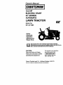
Owner's Manual
ICRAFTSMAH'I
15.5 HP
ELECTRIC START
42" MOWER
AUTOMATIC
LAWN TRACTOR
EZ
Model No.
917.271064
•
•
•
•
Safety
Assembly
Operation
Maintenance
• Repair Parts
This product has a low emission engine whl¢h operates
differently from previously built engines. Before you start the englne, read end understand this Owner's Manual.
CAUTION:
For answers to your questions
Read and follow all Safety
Rules and Instructions before
aboutthisproduct, Call:
operating this equipment,
Sears Craftsman Help Line
5 am - 5 pm, Mon - Sat
1-800-659-5917
Sears, Roebuck and Co., Hoffman Estates, II 60179
Visit our Craftsman website:www.sears.com/craftsman
Warranty ............................................... 2
Safety Rules ......................................... 3
Product Specifications.......................... 6
Assembly.............................................. 8
Operation............................................ 11
Maintenance....................................... 18
Maintenance Schedule ...................... 18
Service and Adjustments .................... 23
Storage ...............................................
29
Troubleshooting ................................. 30
Repair Parts ........................................ 34
Parts Ordedng ..................... Back Cover
LIMITED TWO YEAR WARRANTYON CRAFTSMAN RIDING EQUIPMENT PARTS
For two (2) years from the date of purchase,if this CraftsmanRiding Equipmentis
maintained,lubricated and tuned up accordingto the instructionsin the owners
manual, Sears will repairor replace,free of charge, any parts found to be defectivein
matedal or workmanship.Warranty service is availablefree of charge by takingyour
Craftsmanridingequipmentto yournearest Sears Service Center. In-homewarranty
service is available but a tripcharge will apply.This warrantyappliesonly whilethis
productis in the UnitedStates.
Thts Warrantydoes not cover:
• Expendableitems whichbecome worn duringnormal use, such as blades, spark
plugs,air cleaners, belts and oil filters.
• Tire replacementor repaircaused by puncturesfrom outsideobjects,such as nails,
thorns,stumps,or glass.
• Repairs necessarybecause of operatorabuse, includingbut not limitedto, damage
caused by towing objectsbeyondthe capabilityof the ddingequipment,impacting
objectsthat bend the frame or crankshaft,or over speedingthe engine.
• Repairs necessary because of operator negligence,includingbut not limitedto,
electricaland mechanicaldamage caused by improperstorage, failure to use the
propergrade and amountof engine oil, failure to keep the deck clear of flammable
debris,or the failure to maintainthe equipmentaccordingto the instructions
containedin the owner'smanual.
• Engine (fuel system)cleaningor repairscaused by fuel determinedto be contaminated or oxidized (stale). In general,fuel shouldbe used withinthirty(30) daysof its
purchase date.
• Ridingequipmentused for commercialor rentalpurposes.
LIMITED 90 DAY WARRANTY ON BATTERY
For ninety (90) days from date of purchase, if any battery included with this riding
equipmedt proves defective in material or workmanship and our testing determines
the battery will not hold a charge, Sears will replace the battery at no charge. Warranty
service is available free of charge by taking your Craftsman riding equipment to your
nearest Sears Service Center. In-home warranty service is available but a trip charge
will apply. This warranty applies only while this product is in the United States.
TO LOCATE THE NEAREST SEARS SERVICE CENTER OR TO SCHEDULE INHOME WARRANTY SERVICE, SIMPLY CONTACT SEARS AT 1-8004-MY-HOME
This Warranty gives you specific legal rights, and you may also have other rights
which may vary from state to state.
Seam, Roebuck and Co., D/817 WA, Hoffman Estates, IL 60179
IMPORTANT:
Thiscuttingmachine
is capable
ofamputating
handsandfeet
and
throwing, objects. Failure to observe the following safety instructions could result in
serious injury or death.
I. GENERAL OPERATION
II. SLOPE OPERATION
• Read, understand, and follow all
Slopes ere a major factor related to loss-ofinstructions in the manual and on the
control and tipover accidents, which can
machine before starting.
result in severe in ury or death. All slopes
• Only allow responsible adults, who are
require extra caution. If you cannot back up
familiar with the instructions, to operate
the slope or if you feel uneasy on it, do not
the machine.
mow it.
• Clear the area of objects such as
DO:
rocks, toys, wire, etc., which could be
• Mow up and down slopes, not across.
picked up and thrown by the blade.
• Remove obstacles such as rocks, tree
• Be sure the area is clear of other
limbs, etc.
people before mowing. Stop machine
• Watch for holes, ruts, or bumps.
if anyone enters the area.
Uneven terrain could overturn the
• Never carry passengers.
machine. Tall grass can hide obstacles.
• Do not mow in reverse unless abso• Use slow speed. Choose a low gear
lutely necessary. Always look down
so that you will not have to stop or shift
and behind before and while backing.
while on the slope.
• Be aware of the mower discharge
• Follow the manufacturer's recommendirection and do not point it at anyone.
dations for wheel weights or counterDo not operate the mower without
weights to improve stability.
either the entire grass catcher or the
• Use extra care with grass catchers or
guard in place.
other attachments. These can change
• Slow down before tuming.
the stability of the machine.
• Never leave a running machine
• Keep all movement on the slopes slow
unattended. Always turn off blades, set
and gradual. Do not make sudden
parking brake, stop engine, and
changes in speed or direction.
remove keys before dismounting.
• Avoid starting or stopping on a slope. If
• Turn off blades when not mowing.
tires lose traction, disengage the
• Stop engine before removing grass
blades and proceed slowly straight
catcher or unclogging chute,
down the slope.
• Mow only in daylight or good artificial
DO NOT:
light.
• Do not turn on slopes unless neces• Do not operate the machine while
sary, and then, tum slowly and graduunder the influence of alcohol or drugs.
ally downhill, if possible.
• Watch for traffic when operating near or
• Do not mow near drep-offs, ditches, or
crossing roadways.
embankments. The mower could
• Use extra care when loading or
suddenly tum over if a wheel is over
unloading the machine into a trailer or
the edge of a cliff or ditch, or if an edge
truck.
caves in.
• Data indicates that operators, age 60
• Do not mow on wet grass. Reduced
years and above, are involved in a
traction could cause sliding.
large percentage of riding mower• Do not try to stabilize the machine by
related injuries. These operators
putting your foot on the ground.
should evaluate their ability to operate
• Do not use grass catcher on steep
the riding mower safely enough to
slopes.
protect themselves and others from
serious injury.
3
IlL CHILDREN
Tragicaccidentscan occur if the operator
is not alert to the presenceof children.
Chiidranare often attracted to the
machineand the mowingactivity, Never
assume that childrenwin remain where
you lastsaw them.
• Keep childrenout of the mowing area
and underthe watchfulcare of another
responsibleadult.
• Be alert and turn machineoff if children
enter the area.
• Before and when backing,look behind
and downfor small children.
• Never carry children. They may fall off
and be seriouslyinjuredor interfere
with safe machineoperation.
• Never allow childrento operate the
machine.
• Use extra care when approachingblind
comers,shrubs,trees, or otherobjects
that may obscurevision.
IV. SERVICE
• Use extra care in handlinggasoline
and otherfuels. They are flammable
and vaporsare explosive.
- Use only an approvedcontainer.
- Never remove gas cap or add fuel
with the engine running,Allow
engine to cool before refueling.Do
not smoke.
- Never refuelthe machineindoors.
- Never store the machineor fuel
containerinsidewhere there is an
open flame, such as a water heater.
• Be sure the area is clear of other
people before mowing. Stop machine if
anyone enters the area.
• Never carry passengers or children
even with the blades off.
• Do not mow in reverse unless absolutely necessary. Always look down
and behind before and while backing.
• Never carry children. They may fall off
and be seriously injured or interfere
with safe machine operation.
• Keep children out of the mowing area
and under the watchful care of another
responsible adult.
4
Never run a machineinsidea closed
area.
Keep nuts and bolts, especiallyblade
attachmentbolts,tightand keep
equipmentin good condition.
Never tamper with safety devices.
Check their proper operationregularly.
Keep machinefree of grass,leaves, or
otherdebds build-up.Clean oil or fuel
spillage. Allow machineto cool before
storing.
Stop and inspectthe equipmentif you
stdkean object. Repair, if necessary,
before restarting.
Never make adjustmentsor repairs
with the engine running.
Grass catchercomponentsare subject
to wear, damage, and deterioration,
whichcould expose movingparts or
allow objectsto be thrown. Frequently
check componentsand replace with
manufacturer'srecommendedparts,
when necessary.
Mower blades are sharpand can cut.
Wrap the blade(s)or wear gloves, and
use extra cautionwhen servicingthem.
Check brake operationfrequently.
Adjustand service as required.
• Be alert and turn machine off if children
enter the area.
• Before and when backing, look behind
and down for small children.
• Mow up and down slopes (15 ° Max),
not across.
• Remove obstacles such as rocks, tree
limbs, etc.
• Watch for holes, ruts, or bumps.
Uneven terrain could overturn the
machine. Tall grass can hide obstacles.
• Use slow speed. Choose a low gear so
that you will not have to stop or shift
while on the slope.
• Avoid starting or stopping on a slope. If
tires lose traction, disengage the
blades and proceed slowly straight
down the slope.
• If machine stops while going uphill,
disengage blades, shift into reverse
and back down slowly.
• Do not turn on slopes unless necessary, and then, turn slowly and gradually downhill, if possible.
CAUTION: Tow only the attachment
that are recommended by and comply
with specifications of the manufacturer c
your tractor. Use common sense when
towing. Operate only at the lowest
possible speed when on a slope. Too
heavy of a load, while on a slope, is
dangerous, Tires can lose traction with
the ground and cause you to lose centre
of your tractor.
,&_WARNING:
Engine exhaust, some ol
its constituents, and certain vehicle
components contain or emit chemicals
known to the State of California to cause
cancer and birth defects or other reproductive harm.
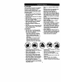
,_Look for this symbol to point out
important safety precautions. It means
CAUTION!H BECOMEALERT!I! YOUR
SAFETY IS INVOLVED.
_WARNING:
Battery posts, terminals
and related accessories contain lead an
lead compounds, chemicals known to th
State of California to cause cancer and
birth defects or other reproductive han'n
Wash hands after handling.
CAUTION: In order to prevent
.accidental starting when setting up,
transporting, adjusting or making repairs,
always disconnect spark plug wire and
place wire where it cannot contact spark
plug.
CAUTION: Do not coast down a hill
in neutral, you may lose control of the
tractor.
5
PRODUCT SPECIFICATIONS
GASOLINE
CAPACITY
ANDTYPE:
We have competent,well-trainedtechnicians and the propertoolsto serviceor
repairthis tractor.
Please read and retainthis manual. The
instructionswill enable you to assemble
and maintainyourtractorproperly.
Alwaysobservethe "SAFETY RULES".
1,25 GALLONS
UNLEADED
REGULAR
OILTYPE
SAE10W30(above
32°F)
API-SF-SJ):
SAE5W-30(below32°F
OIL CAPACITY: W/FILTER:4.0 PINTS
W/OFILTER:3.5 PINTS
SPARK PLUG: CHAMPION RC12YC
GAP: .040")
VALVE
CLEARANCE: NOT ADJUSTABLE
GROUND
FORWARD:5.5
SPEED(MPH): REVERSE: 2.4
TIRE
FRONT:
14 PSI
REAR:
10 PSI
CHARGING
SYSTEM:
15AMPS @ 3600 RPM
BATTERY:
AMP/HR: 30
MIN. CCA: 240
CASE SIZE: U1R
BLADE BOLT
27-35 FT. LBS.
TORQUE:
REPAIR AGREEMENT
A Repair Agreement is available on this
product. Contact your nearest Sears
store for details.
CUSTOMER RESPONSIBILITIES
• Read and observe the safety rules.
• Follow a regular schedule in maintaining, caring for and using your tractor.
• Follow the instructions under =Maintenance" and =Storage" sections of this
owner's manual.
_LWARNING:
This tractor is equipped
with an intemal combustion engine and
should not be used on or near any
unimproved forest-covered, brushcovered or grass-covered land unless the
engine's exhaust system is equipped with
a spark arrester meeting applicable local
or state laws (if any). If a spark arrester is
used, it should be maintained in effective
working order by the operator.
In the state of California the above is
required by law (Section 4442 of the
California Public Resources Code).
Other states may have similar laws.
Federal laws apply on federal lands. A
spark arrester for the muffler is available
through your nearest Sears service
center (See REPAIR PARTS section of
this manual).
CONGRATULATIONS on your purchase
of a new tractor. It has been designed,
engineeredand manufacturedto give
you the best possibledependabilityand
performance,
Shouldyou experience any problem you
cannot easily remedy, please contact a
Sears or other qualified servicecenter.
6
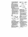
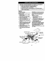
Steering
Wheel Insert
Steering Wheel
(1) Large Flat Washer
washer 3/8
W
3/8-16 x 1
Steedng _
Boot
/
_
(5_I6L'l°C8knut
J/
(1) Hex Bolt
5/16-18 x 1-1/4
Steering
Extension
Shaft
Wheel Adapter
Steering
_
Seat
(_Washer
17/32 x 1-3/16 x 12
Gauge
_(1)
_) Shoulder
olt 5/16-18
Knob
For Future Use
Keys
Slope Sheet
(2) Keys
7
Video Cassette
Your new tractor has been assembled at the factory with exception of those parts left
unassembled for shipping purposes. To ensure safe and proper operation of your
tractor all parts and hardware you assemble must be tightened securely. Use the
correct tools as necessary to insure proper tightness. Review the video cassette before
you begin.
TOOLS REQUIRED FOR ASSEMBLY
_
A socket wrench set will make assembly
easier. Standard wrench sizes you need
are listed below.
(1) 9/16" wrench
(1) Pliers
(2) 1/2" wrench
(1) Utility knife
(1) Tire pressure gauge
When right or left hand is mentioned in
this manual, it means, from your point of
view, when you are in the operating
position (seated behind the steering
wheel).
TO REMOVE TRACTOR FROM
,_3/8
Insert
Hex Bolt
Lock Washer
_----_Large
_
Flat
Washer
CARTON
UNPACK CARTON
1. Remove all accessible loose parts
and parts cartons from carton.
2. Cut, from top to bottom, along lines on
all four comers of carton, and lay
panels flat.
3. Check for any additional loose parts
or cartons and remove.
BEFORE REMOVINGTRACTOR
FROM SKID
ATTACH STEERING WHEEL
6. Assemble large flat washer, 3/8 lock
washer, 3/8 hsx bolt and tighten
securely.
7. Snap steering wheel insert into center"
of steering wheel.
8. Remove protective materials from
tractor hood and grill
IMPORTANT: Check for and remove any
staples in skid that may puncture tires
where tractor is to roll off skid.
ASSEMBLE EXTENSION SHAFT AND
BOOT
1. Slide extension shaft onto lower
steering shaft. Align mounting holes
in extension and lower shafts and
install 5/16 hex bolt and Iocknut.
Tighten securely.
2. Place tabs of steering boot over tab
slots in dash and push down to
secure.
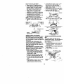
HOWTO SET UPYOURTRACTOR
CHECK BA'I'rERY
I. Liftseat pan to raisedpositionand
open batterybox door.
NOTE: Ifthis batteryis put intoservice
after monthand year indicatedon label
(label located between terminals)charge
batteryfor minimumof one hour at 6-10
amps. (See "BATTERY" in Maintenance
sectionof this manual for charging
instructions).
INSTALL STEERING WHEEL
3. Position front wheels of the tractor so
they are pointing straight forward.
4, Remove steering wheel adapter from
steering wheel and slide adapter onto
steering shaft extension.
5. Position steering wheel so cross bars
are horizontal (left to right) and slide
inside boot and onto adapter.
8
Terminal
Batter
Door
Termin_
INSTALL SEAT
Adjust seat before tightening adjustment
knob,
1. Remove adjustment knob and flat
washer secudng seat to cardboard
packing and set aside for assembly of
seat to tractor.
2. Pivot seat upward and remove from
the cardboard packing. Remove the
cardboard packing and discard.
3. Place seat on seat pan and assemble
shoulder bolt. Tighten shoulder bolt
securely.
4. Assemble adjustment knob and flat
washer loosely. Do not tighten.
5. Lower seat into operating position
and sit on seat.
6. Slide seat until a comfortable position
is reached which allows you to press
clutch/brake pedal all the way down.
7. Get off seat without moving its
adjusted position.
8. Raise seat and tighten adjustment
knob securely.
A/[ustment,
Knob
_
Flat Washer
NOTE: You may now roll or drive your
tractor off the skid. Follow the appropdate instruction below to remove the
tractor from the skid.
TO ROLLTRACTOR
OFF SKID (See
Operation section for location and
function of controls)
1. Press lift lever plunger and raise
attachment lift lever to its highest
position.
2. Release parking brake by depressing
clutch/brake pedal.
3. Place freewheel control in freewheeling position to disengage transmission (See "TO TRANSPORT" in the
Operation section of this manual).
4. Roll tractor forward off skid.
5. Remove banding holding deflector
shield up against tractor.
TO DRIVETRACTOR
OFF SKID (See
Operation section for location and
function of controls)
WARNING: Before starting, read,
understand and follow all insfructions in
the Operation section of this manual. Be
sure tractor is in a well-ventilated area. Be
sure the area in front of tractor is clear of
other people and objects.
1. Be sure all the above assembly steps
have been completed.
2. Check engine oil level and fill fuel
tank with gasoline.
3. Place freewheel control in "transmission engaged" position.
4. Sit on seat in operating position,
depress clutch/brake pedal and set
the parking brake.
5. Place motion control lever in neutral
(N) position.
6. Press lift lever plunger and raise
attachment lift lever to its highest
position.
7. Start the engine. After engine has
started, move throttle control to idle
position.
8. Release parking brake.
9. Slowly move the motion control lever
forward and slowly drive tractor off
skid.
10.Apply brake to stop tractor, set parking
brake and place motion control lever
in neutral position.
11 .Turn ignition key to "OFF" position.
Continue with the instructions that follow.
9
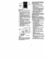
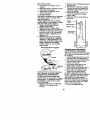
INSTALL MULCHER PLATE
(If previously removed)
1. Raise and hold deflectorshield in
updght position.
2. Place front of mulcherplate over front
of mower deck openingand slide into
place, as shown.
3. Hook front latch intoholeon front of
mower deck.
4. Hook roar latch intohole on back of
mower deck.
CHECK BRAKE SYSTEM
After you learn how to operateyour
tractor,checkto see thatthe brake is
properlyadjusted. See "TO ADJUST
BRAKE"in the Service and Adjustments
sectionof this manual.
V'CHECKLIST
Beforeyou operate and enjoyyour new
tractor,we wishto assure that you receive
the best performanceand satisfaction
from thisQualityProduct.
Please reviewthe following checklist:
_CAUTION:
Do not removedeflector
shieldfrom mower.Raise and hold shield ,/All assemblyinstructionshave been
completed.
when attachingmulcher plate and allow it
,/No
remaininglooseparts in carton.
to rest on plate while in operation.
,/Battery is properlypreparedand
Mufchsr
charged. (MinimumI hourat 6 amps).
Plate
,/Seat is adjustedcomfortablyand
Shield
tightenedsecurely.
,/,All tires are propodyinflated. (For
shippingpurposes,the tires were
ovednflatedat the factory).
,/Be sure mower deck is propedyleveled
side-to-side/front-to-rear
for best cutting
Latch
results. (Tires mustbe propedyinflated
Hooks
for leveling).
.,(Check mowerand ddve belts. Be sure
TO CONVERTTO BAGGING OR
they are routedproperlyaroundpulleys
DISCHARGING
and inside all belt keepers.
Simply remove mulcherplate and store in ,/Check widng. See that all connections
are stillsecure and wires are propedy
a safe place.Yourmower is now readyfor
clamped.
dischargingor installationof optional
,/Before
ddvingtractor,be sure freegrass catcher accessory.
wheel controlis in ddve position.
NOTE: It is not necessaryto change
While learninghow to use yourtractor,
blades. The mulcherblades are depay extra attentionto the following
signedfor dischargingand baggingalso.
importantitems:
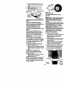
CHECKTIRE PRESSURE
,/ Engineoil is at properlevel.
The tires on yourtractorwere ovednflated ,it Fuel tankis filled withfresh, clean,
regular unleaded gasoline.
at the factory for shippingpurposes.
Correcttire pressure _simportantfor best
,/Become familiar with all controls - their
cuttingperformance.
locationand function. Operate them
• Reducetire pressureto PSI shown in
beforeyou start the engine.
"PRODUCT SPECIFICATIONS" section ,/Be sure brake systemis in safe
of this manual.
operating condition.
CHECK DECK LEVELNESS
,/It is importantto purge the transmission
before operatingyourtractorfor the first
For best cutting results, mower housing
time. Followproperstartingand
should be propedy leveled. See "TO
LEVEL MOWER HOUSING in the
transmissionpurginginstructions(See
"TO START ENGINE"and =PURGE
Service and Adjustments section of this
manual.
TRANSMISSION" in the Operation
sectionof this manual).
CHECK FOR PROPER
ALL BELTS
POSITION
OF
See the figures that are shown for
replacingmotion and mower blade drive
belts in the Service and Ad ustments
section of ths manual. Verfy that the
belts are routed correctly.
10
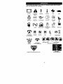
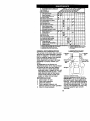
These symbols may appear OR your tractor or in literature supplied with the product.
Learn and understand their meaning.
A ,=
BATTERY
CAUTION OR
WARNtNG
REVERSE
FORWARD
ENGINE ON
ENGINE OFF
OIL PRESSURE
LIGHTS ON
OVER TEMP
LIGHT
FUEL
CHOKE
MOWER HEIGHT
PARKING BRAKE
LOCKED
UNLOCKED
_'1 R N H
ATTACHMENT
CLUTCH ENGAGED
REVERSE
NEUTRAL
HIGH
KEEP AREA CLEAR
IGNITION
ATTACHMENT
CLUTCH DISENGAGED
FAST
SLOW
MOWER LIFT
L
c®_I
LOW
PARKING BRAKE
SLOPE HAZARDS
(SEE SAFETY RULES SECTION)
FREE WHEEL
(Automatic Models only)
DANGER, KEEP HANDS AND FEET AWAY
11
KNOWYOURTRACTOR
READ THIS OWNER'S MANUAL AND SAFETY RULES BEFORE OPERATING
YOUR TRACTOR
Compare the illustrationswith your tractorto familiarize yourselfwith the locationsof
various controlsand adjustments. Save this manualfor future reference.
Attachment
Clutch
Light Switch
Ignition Switch
Ammeter
J
Throttle/Choke
Control
lift
Lever
Plunger
Attachment
Lift Lever
Clutch/Brake
Pedal
Height
Adjustment
Indicator
Freewheel
Control
Parking Brake Lever
Moron
Lever
Control
Our tractors conform to the safety standards of the American
National Standards Institute.
AMMETER
- Indicates charging (+) or
discharging
(-) of
battery. LEVER
AI"FACHMENT
CLUTCH
Used
to engage the mower blades, or other
attachments mounted to your tractor.
ATTACHMENT LIFT LEVER - Used to
raise, lower, and adjust the mower deck
or other attachments mounted to your
tractor.
CLUTCWBRAKE PEDAL - Used for
declutching and braking the tractor and
starting the engine.
MOTION CONTROL LEVER - Selects the
speed and direction of tractor.
IGNITION SWITCH - Used for starting and
stopping the engine.
LIFT LEVER PLUNGER - Used to release
attachment lift lever when changing its
position.
LIGHT SWITCH - Turns the headlights on
and off.
PARKING BRAKE LEVER - Locks clutch/
brake pedal into the brake position.
THROTTLE/CHOKE CONTROL - Used
for starting and controlling engine speed.
FREEWHEEL CONTROL Disengagages transmission for pushing
or slowly towing the tractor with the
engine off.
12
L
,i
The operation of any tractor can result in foreign objects thrown into the
eyes, which can result in severe eye damage• Always wear safety
glasses or eye shields while operating your tractor or performing any
adjustments or repairs. We recommend a wide vision safety mask over
spectacles or standard safety glasses.
HOWTO USEYOURTRACTOR
TO SET PARKING BRAKE
Your tractor is equipped with an operator
presence sensing switch. When engine
is running, any attempt by the operator to
leave the seat without first setting the
parking brake will shut off the engine.
1. Depress clutch/brake pedal into full
"BRAKE" position and hold•
2. Place parking brake lever in "ENGAGED" position and release
pressure from clutch/brake pedal.
Pedal should remain in "BRAKE"
position. Make sure parking brake will
hold tractor secure.
Throttle/
AttachmentClutch Lever
Choke
=Engaged"
• Position
• IgnitionKey
=Disengaged"
Position
Clutch/
Brake
Brake Peda
Position
Position
Lever
STOPPING
MOWER BLADES • To stop mower blades,move attachment clutch lever to "DISENGAGED"
position,
GROUND DRIVE • To stop ground drive, depress clutch/
brake pedal into full "BRAKE" position.
• Move motion control lever to neutral (N)
position.
IMPORTANT." The motion control lever
does not return to neutral (N) position
when the clutch/brake pedal is depressed.
ENGINE • Move throttle control to slow position.
NOTE: Failure to move throttle control to
slow position and allowing engine to idle
before stopping may cause engine to
=backfire".
•Tum ignition key to =OFF" position and
remove key. Always remove key when
leaving tractor to prevent unauthorized
use,
J
E
• Never use choke to stop engine.
IMPORTANT: Leaving the ignition switch
in any position other than "OFF" will
cause the battery to be discharged,
(dead).
NOTE: Under certain conditions when
tractor is standing idle with the engine
running, hot engine exhaust gases may
cause "browning" of grass. To eliminate
this possibility, always stop engine when
stopping tractor on grass areas.
p_CA,UTION: AI,way_;s.toptr_ctor comely, as aescrleeaaDove,
Defora
leaving the operator's position; to empty
grass catcher, etc.
TO USE THRO'I'rLE CONTROL
Always operate engine at full throttle.
• Operating engine at less than full
throttle reduces the battery charging
rate.
• Full throttle offers the best bagging and
mower performance,
TO MOVE FORWARD AND
BACKWARD
The dire(;tion and speed of movement is
controlled by the motion control lever.
1. Start tractor with motion control lever
in neutral (N) position.
2. Release parking brake and clutch/
brake pedal
3. Slowly move motion control lever to
desired position•
TO ADJUST MOWER CUTTING HEIGHT
The position of the attachment lift lever
determines the cutting height.
• Grasp lltt
lever.
• Press plunger with thumb and move
lever to desired position.
The cutting height range is approximately 1-1/2 to 4"• The heights are
measured from the ground to the blade
tip with the engine not running. These
heights are approximate and may vary
depending upon soil conditions, height of
grass and types of grass being mowed.
• The average lawn should be cut to
approximately 2-1/2 inches during the
cool season and to over 3 inches
during hot months• For healthier and
better looking lawns, mow ellen and
after moderate growth.
13
• For best cutting performance, grass
over 6 inches in height should be
mowed twice. Make the first cut
relatively high; the second to desired
height.
TO ADJUST GAUGE WHEELS
Gauge wheels are propedy adjusted
when they are slightly off the ground
when mower is at the desired cutting
height in operating position. Gauge
wheels then keep the deck in proper
position to help prevent scalping in most
terrain conditions.
NOTE: Adjust gauge wheels with tractor
on a flat level surface.
1. Adjust mower to desired cutting height
(See "TO ADJUST MOWER CUTTING
HEIGHT" in the Operation section of
this manual).
2. With mower in desired height of cut
position, gauge wheels should be
assembled so they are slightly off the
ground. Install gauge wheel in
appropriate hole with shoulder bolt, 3/
8 washer, and 3/8-16 Iocknut and
tighten securely.
3. Repeat for opposite side installing
gauge wheel in same adjustment
hole.
Gauge
Wheel
Mounting _'_J_
_ _.
Gauge Wheel
TO OPERATE MOWER
Your tractor is equipped with an operator
presence sensing switch. Any attempt by
the operator to leave the seat with the
engine running and the attachment
clutch engaged will shut off the engine.
1. Select desired height of cut.
2. Start mower blades by engaging
attachment clutch control.
TO STOP MOWER BLADES disengage attachment clutch control.
,_ CAUTION: Do not operate the
mower without either the entire grass
catcher, on mowers so equipped, or the
deflector shield in place.
AttachmentClutch Lever
Attachernnt
Position
Position
"_
Low
Position
Deflector
Shield
TO OPERATE ON HILLS
_CAUTION:
Do not drive up or down
hills with slopes greater than 15 ° and do
not drive across any slope.
• Choose the slowest speed before
starting up or down hills.
• Avoid stopping or changing speed on
hills.
• If slowing is necessary, move throttle
control lever to slower position.
• If stopping is absolutely necessary,
push clutch/brake pedal quickly to
brake position and engage parking
brake.
• Move motion control lever to neutral (N)
position.
IMPORTANT: The motion control lever .
does not return to neutral (N) position
when the clutch/brake pedal is depressed.
• To restart movement, slowly release
parking brake and clutch/brake pedal.
• Slowly move motion control lever to
slowest setting.
• Make all turns slowly.
TO TRANSPORT
When pushing or towing your tractor, be
sure to disengage transmission by
placing freewheel control in freewheeling
position. Free wheel control is located at
the rear drawbar of tractor.
1. Raise attachment lift to highest
position with attachment lift control.
2. Pull freewheel control out and down
into the slot and release so it is held in
the disengaged position.
• Do not push or tow tractor at more than
two (2) MPH.
• To reengage transmission, reverse
above procedure.
14
NOTE:Toprotect
hoodfrom damage
when transportingyourtractoron a truck
or a trailer,be sure hood is closedand
securedto tractor. Use an appropriate
meansof tying hoodto tractor(rope, cord,
etc.).
TOWING CARTS AND OTHER ATTACHMENTS
Tow onlythe attachmentsthat are
recommendedby and complywith
specificationsof the manufacturer of your
tractor.Use commonsensewhen towing.
Tooheavy of a load, whileon a slope, is
dangerous.Tires can lose tractionwith
the groundand cause you to lose control
of yourtractor.
BEFORE STARTINGTHE
ENGINE
CHECK ENGINE OIL LEVEL
The engine in your tractor has been
shipped, from the factory, already filled
with summer weight oil.
1. Check engine oil with tractor on level
ground.
2. -Unthread and remove oil fill cap/
dipstick; wipe oil off. Reinsert the
dipstick into the tube and rest oil fill
cap on the tube. Do not thread the
cap onto the tube. Remove and read
oil level. If necessary, add oil until
"FULL" mark on dipstick is reached.
Do not overfill.
• For cold weather operation you should
change oil for easier starting (See "OIL
VISCOSITY CHART" in the Maintenance section of this manual).
• To change engine oil, see the Maintenance section in this manual.
Oil Fill Cap/
ADD GASOLINE
• Fill fuel tank. Use fresh, clean, regular
unleaded gasoline with a minimum of
87 octane. (Use of leaded gasoline
will increase carbon and lead oxide
deposits and reduce valve life). Do not
mix oil with gasoline. Pumhase fuel in
quantities that can be used within 30
days to assure fuel freshness.
IMPORTANT: When operating in
temperatures below 32°F(0°C), use
fresh, clean winter grade gasoline to
help insure good cold weather starting.
_iLWARNING: Experience indicates that
alcohol blended fuels (called gasohol or
using ethanol or methanol) can attract
moisture which leads to separation and
formation of acids dudng storage. Acidic
gas can damage the fuel system of an
engine while in storage. To avoid engine
problems, the fuel system should be
emptied before storage of 30 days or
longer. Drain the gas tank, start the
engine and let it run until the fuel lines
and carburetor are empty. Use fresh fuel
next season. See Storage Instructions
for additional information. Never use
engine or carburetor cleaner products in
the fuel tank or permanent damage may
OCCUr,
JiLCAUTION: Fill to bottom of gas tank
filler neck. Do not overfill. Wipe off any
spilled oil or fuel. Do not store, spill or
use gasoline near an open flame.
TO START ENGINE
When startingthe enginefor the firsttime
or if the engine has runout of fuel, it will
take extra crankingtime to movefuel
from the tank to the engine.
1. Be sure freewheelcontrolis in the
transmissionengaged position.
2. Sit on seat in operatingposition,
depressclutch/brakepedal and set
parking brake.
3. Place motioncontrollever in neutral
(N) position.
4. Move attachment clutchto =DISENGAGED" position.
5. Move throttlecontrolto choke
position.
Dipstick
15
NOTE: Before starting, read the warm
and cold starting procedures below.
6. Insert key into ignition and turn key
clockwise to "START' position and
release key as soon as engine starts.
Do not run starter continuously for
more than fifteen seconds per minute.
If the engine does not start after
several attempts, move throttle control
to fast position, wait a few minutes and
try again. If engine still does not start,
move the throttle control back to the
choke position and retry.
WARM WEATHER STARTING (50 o F and
above)
7. When engine starts, move the throttle
control to the fast position.
• The attachments and ground drive can
now be used, If the engine does not
accept the load, restart the engine and
allow it to warm up for one minute
using the choke as described above.
COLD WEATHER STARTING ( 50 ° F and
below)
7. When engine starts, allow engine to
run with the throttle control in the
choke position until the engine runs
roughly, then move throttle control to
fast position. This may require an
engine warm-up period from several
seconds to several minutes, depending on the temperature.
AUTOMATIC TRANSMISSION WARM UP
Before driving the unit in cold weather,
the transmission should be warmed up as
follows:
1. Be sure the tractor is on level ground.
2. Place the motion control lever in
neutral. Release the parking brake
and let the clutch/brake slowly return
to operating position.
3. Allow one minute for transmission to
warm up. This can be done during
the engine warm up pedod.
• The attachments can also be used
dudng the engine warm-up pedod after
the transmission has been warmed up.
NOTE: If at a high altitude (above 3000
feet) or in cold temperatures (below 32 F)
the carburetor fuel mixture may need to
be adjusted for best engine performance.
See "TO ADJUST CARBURETOR" in the
Service and Adjustments section of this
manual.
PURGETRANSMISSlON
,_CAUTION:
Never engage or disengage freewheel lever while the engine is
running.
To ensure proper operation and perfor.
mance, it is recommended that the
transmission be purged before operating
tractor for the first time. This procedure will
remove any trapped air inside the transmission which may have developed during
shipping of your tractor.
IMPORTANT: Should your transmission
require removal for service or replacement,
it should be purged after reinstallation
before operating the tractor.
1. Place tractor safely on level surface
with engine off and parking brake set.
2. Disengage transmission by placing
freewheel control in freewheeling
position (See "TO TRANSPORT" in
this section of manual).
3. Sitting in the tractor seat, start engine.
After the engine is running, move
throttle control to slow position. With
motion control lever in neutral (N)
position, slowly disengage clutch/
brake pedal.
4. Move motion control lever to full
forward position and hold for five (5)
seconds. Move lever to full reverse
position and hold for five (5) seconds.
Repeat this procedure three (3) times.
NOTE: During this procedure there will be
no movement of drive wheels. The air is
being removed from hydraulic drive
system.
5. Move motion control lever to neutral
(N) position. Shut- off engine and set
parking brake.
6. Engage transmission by placing
freewheel control in driving position
(See "TO TRANSPORT" in this section
of manual).
7. Sifting in the tractor seat, start engine.
After the engine is running, move
throttle control to half (1/2) speed. With
motion control lever in neutral (N)
position, slowly disengage clutch/
brake pedal.
8. Slowly move motion control lever
forward, after the tractor moves
approximately five (5) feet, slowly
move motion control lever to reverse
position. After the tractor moves
approximately five (5) feet return the
motion control lever to the neutral (N)
position. Repeat this procedure with
the motion control lever three (3)
times.
16
Your tractor is now purged and now ready
for normal operation.
MULCHING
MOWINGTIPS
IMPORTANT: For best performance,
keep mower housing free of built-up
grass and trash. Clean after each use.
• The special mulching blade will recut
the grass clippings many times and
reduce them in size so that as they fall
onto the lawn they will disperse into the
grass and not be noticed. Also, the
mulched grass will biodegrade quickly
to provide nutrients for the lawn.
Always mulch with your highest engine
(blade) speed as this will provide the
best recutting action of the blades.
• Avoid cutting your lawn when it is wet.
Wet grass tends to form clumps and
interferes with the mulching action.
The best time to mow your lawn is the
early afternoon. At this time the grass
has dried and the newly cut area will
not be exposed to the direct sun.
• For best results, adjust the mower
cutting height so that the mower cuts off
only the top one-third of the grass
blades. For extremely heavy mulching,
reduce your width of cut on each pass
and mow slowly.
• Certain types of grass and grass
conditions may require that an area be
mulched a second time to completely
hide the clippings. When doing a
second cut, mow across or perpendicular to the first cut path.
• Change your cutting pattern from week
to week. Mow north to south one week
then change to east to west the next
week. This will help prevent matting
and graining of the lawn.
MOWlNGTIPS
• Mower should be properly leveled for
best mowing performance. See "TO
LEVEL MOWER HOUSING" in the
Service and Adjustments section of this
manual.
• The left hand side of mower should be
used for trimming.
• Drive so that clippings are discharged
onto the area that has been cut. Have
the cut area to the right of the tractor.
This will result in a more even distdbution of clippings and more uniform
cutting.
• When mowing large areas, start by
turning to the right so that clippings will
discharge away from shrubs, fences,
driveways, etc. After one or two
rounds, mow in the opposite direction
making left hand turns until finished.
.• If grass is extremely tall, it should be
mowed twice to reduce load and
possible fire hazard from dried clippings. Make first cut relatively high; the
second to the desired height.
• Do not mow grass when it is wet. Wet
grass will plug mower and leave
undesirable clumps. Allow grass to dry
before mowing.
• Always operate engine at full throttle
when mowing to assure better mowing
performance and proper discharge of
material. Regulate ground speed by
selecting a low enough gear to give the
mower cutting performance as well as
the quality of cut desired.
• When operating attachments, select a
ground speed that will suit the terrain
and give best performance of the
attachment being used.
Max 1/3"
J
17
MAINTENANCE SCHEDULE
FILL IN DATES
AS YOU COMPLETE
REGULAR SERVICE
CheCk Brake Operatio_
CheckTire PreSsure
t#'
_1
Check Operator Pre_ence and
T InterlOCk
Systems
Ik/
R C_'kk.Loos_
F._,,
V'
A
SherpervReqlace
Mower Diodes
V',
Vr4
T Lubri(:atk_
Chaut
(1_
I_
CleanBettmyendTerm_ais
VO
I1_
Cr._ktra._x_ Cocking
Adjust
B4ade
_t(s) Tension
I/
0
C;le_k Bstter)' Level
R
Check Engine C41Level
Ks
(1_
change
EngmOil
E CioallAirFlier
N CleanAirScreen
I,K_=:
IV#
Ii_z
_2
Inspect Muffior/Sp_l_ Affester
Rep_ce Og Filter (if equipped)
I_
I_1:
Clee_ Engine Coo;_ng FIOS
V/:
Be_CeS_i_ _'mug
I/
ReplaceAir FilterPaperCWtrioge
I/2
I/
Repl_.e Fuel Fgter
GENERAL
1.
2.
3.
4.
I_
RECOMMENDATIONS
The warranty on this tractor does not cover
items that have been subjected to operator
abuse or negligence. To receive full value
from the warranty, operator must maintain
tractor as instructed in this manual.
Some adjustments will need to be made
periodically to properly maintain your
tractor.
All adjustments in the Service and
Adjustments section of this manual should
be checked at least once each season.
• Once a year you should replace the
spark plug, clean or replace air filter, and
check blades and belts for wear. A new
spark plug and clean air filter assure
proper air-fuel mixture and help your
engine run better and last longer.
BEFORE
I
II_
Adjust Motion Drive Belt(s) Tension
N
V" I
EACH USE
Check engine oil level.
Check brake operation.
Check tire pressure.
Check operator presence and
interlock systems for proper operation.
5. Check for loose fasteners.
LUBRICATION CHART
-- • Spindle
• Sz_dlB _
::: ....
_Front_t_!!
:_:
i
_
Zerk
_ntnV_,e/
Zerk
Beating
(_Engine
!'
,_= __
(_)SAE 30 or 10w30 MOTOR OIL
_)REFER TO MatnteBance "ENGINE"SECTION
IMPORTANT: Do not oil or grease the
pivot points which have special nylon
bearings. Viscous lubricants will attract
dust and dirt that will shorten the life of
the self-lubdcatin_l bearings. If you feel
they must be lubricated, use only a dry,
powdered graphite type lubricant
sparingly.
18
TRACTOR
Always observe safety rules when
performing any maintenance.
BRAKE OPERATION
If tractor requires more than six (6) feet
stopping distance at high speed in
highest gear, then brake must be adjusted. (See "TO ADJUST BRAKE" in the
Service and Adjustments section of this
manual).
TIRES
• Maintain proper air pressure in all tires
(See "PRODUCT SPECIFICATIONS"
section of this manual).
• Keep tires free of gasoline, oil, or insect
control chemicals which can harm
rubber.
• Avoid stumps, stones, deep ruts, sharp
objects and other hazards that may
cause tire damage.
NOTE: To seal tire punctures and prevent
flat tires due to slow leaks, tire sealant
may be purchased from your local parts
dealer. Tire sealant also prevents tire dry
rot and corrosion.
OPERATOR PRESENCE SYSTEM
Be sure operator presence and intedock
systems are working properly. If your
tractor does not function as described,
repair the problem immediately.
• The engine should not start unless the
clutch/brake pedal is fully depressed
and attachement clutch control is in the
disengaged position.
• When the engine is running, any
attempt by the operator to leave the
seat without first setting the parking
brake should shut off the engine.
• When the engine is running and the
attachment clutch is engaged, any
attempt by the operator to leave the
seat should shut off the engine.
• The attachment clutch should never
operate unless the operator is in the
seat.
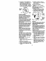
BLADE CARE
For best results mower blades must be
kept sharp. Replace bent or damaged
blades.
IMPORTANT: To ensure proper assembly,
center hole in blade must align with star
on mandrel assembly.
4. Reassemble hex bolt, lock washer
and fiat washer in exact order as
shown.
5. Tighten bolt securely (27-35 Ft. Lbs.
torque).
IMPORTANT:
Blade bolt is grade 8 heat
treated.
Mandrel Assembly
Trailing
e Up
Blade Center
Hole
Ftat Washer
Lock Washer
/,
_-'-Hex Bolt
"AGrade 8 heat treatedbolt can be identified
by six lineson the bolt head.
TO SHARPEN BLADE
NOTE: We do not recommend sharpening blade - but if you do, be sure the
blade is balanced.
Care should be taken to keep the blade
balanced. An unbalanced blade will
cause excessive vibration and eventual
damage to mower and engine.
• The blade can be sharpened with a file
or on a gdnding wheel. Do not attempt
to sharpen while on the mower.
• To check blade balance, you will need
a 5/8" diameter steel bolt, pin, or a cone
balancer. (When using a cone balancer, follow the instructions supplied
with balancer.)
NOTE: Do not use a nail for balancing
blade. The lobes of the center hole may
appear to be centered, but are not.
• Slide blade on to an unthreaded
portion of the steel bolt or pin and hold
the bolt or pin parallel with the ground.
If blade is balanced, it should remain in
a hodzontal position. If either end of
the blade moves downward, sharpen
the heavy end until the blade is
balanced.
BLADE REMOVAL
1. Raise mower to highest position to
allow access to blades.
2. Remove hex bolt, lock washer and flat
washer securing blade.
3. Install new or resharpened blade with
trailing edge up towards deck as
shown.
Center Hole
19
BATTERY
Yourtractorhas a batterychargingsystem
whichis sufficientfor normaluse. However, periodicchargingof the batterywith
an automotivecharger will extend its life.
• Keep batteryand terminalsclean.
• Keep battery boltstight.
; Keep small vent holes open.
Recharge at 6-10 amperes for 1 hour.
NOTE: The originalequipmentbatteryon
yourtractoris maintenancefree. Do not
attempt to open or remove capsor covers.
Addingor checkinglevel of electrolyteis
not necessary.
TO CLEAN BATTERYAND TERMINALS
Corrosionand dirton the batteryand
terminalscan cause the batteryto "leak"
power.
1. Open battery box door.
2. DisconnectBLACKbatterycable first
then RED batterycable and remove
batteryfrom tractor.
3. Rinsethe batterywith plain water and
dry.
4. Clean terminalsand battery cable
ends with wire brush unti_blight.
5. Coat terminalswith grease or petroleum jelly.
6. Reinstall battery (See =REPLACING
SATI'ERY" in the SERVICE AND
ADJUSTMENTS sectionof this
manual).
V-BELTS
Check V-beltsfor deteriorationand wear
after 100 hoursof operationand replece
if necessary.The belts are not adjustal_e.
Replacebelts if they beginto slipfrom
wear.
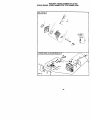
TRANSAXLE
COOLING
The transmission fan and cooling fins
should be kept clean to assure proper
cooling.
Do not attempt to clean fan or transmission while engine is runningor while the
transmission is hot. To prevent possible
damage to seals, do not use high
pressure water or steam to clean
transaxle.
• Inspect cooling fan to be sure fan
blades are intact and clean.
• Inspect cooling fins for did, grass
clippings and other materials. To
prevent damage to seals, do not use
compressed air or high pressure
sprayer to clean cooling fins.
TRANSAXLE
PUMP FLUID
The transaxle was sealed at the factory
and fluid maintenance is not required fc
the life of the transaxle. Should the
transaxle ever leak or require servicing,
contact your nearest authodzed service
center/department.
ENGINE
LUBRICATION
Only use high qualitydetergentoil rated
with API serviceclassificationSF-SJ.
Select the oil'sSAE viscositygrade
accordingto your expected operating
temperature.
Change the oil after every 50 hoursof
operat{onor at leastonce a year if the
tractoris not used for 50 hoursin one
year.
Check the crankcaseoil level before
startingthe engineand after each eight
(8) hoursof operation.Tightenoil fillcal
dipsticksecurelyeach time you checktf
oil level.
TO CHANGE ENGINE OIL
Determine temperature range expected
before oil change. All oil must meet API
service classification SF-SJ.
• Be sure tractor is on level surface.
• Oil wil! drain more freely when warm.
• Catch oil in a suitable container.
1. Remove oil fill cap/dipstick. Be carsf
not to allow dirt to enter the engine
when changing oil.
2. Remove cap from end of drain valve
and install the drain tube onto the
fitting.
3. Unlock drain valve by pushing inwar
slightly and turningcounterclockwise
4. To open, pull out on the drain valve.
5. After oil has drained completely, clo,,
and lock the drain valve by pushing
inward and turning clcckwise until th
pin is in the locked position as show=
6. Remove the drain tube and replace
the cap onto to the end of the drain
valve.
7. Refill engine with oil through oil fill
dipstick tube. Pour slowly. Do not
overfill. For approximate capacity s(
=PRODUCT SPECIFICATIONS"
section of this manual
2O
8. Use gauge on oil fill cap/dipstick for
checking level. Insert dipstick into the
tube and rest the oil fill cap on the
tube. Do not thread the cap onto the
tube when taking reading.
Keep oil
at =FULL" line on dipstick. Tighten cap
onto the tube securely when finished.
Oil DrainValve
c,OcSkee_
and_
Position_
Cap_
Drain
\ Tube
6. Saturate it in engine oil. Wrap it in
clean, absorbent cloth and squeeze to
remove excess oil.
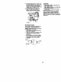
TO SERVICE CARTRIDGE
• Replace a dirty, bent, or damaged
cartddge.
NOTE: Do not wash the paper cartridge
or use pressudzed air, as this will
damage the cartddge.
7. Reinstall the pre-cleaner (cleaned
and oiled) over the paper cartridge.
8. Reassemble air cleaner, wing nut,
cover and tighten knob securely.
Air Cleaner
Knob
i Nut
Foam
CLEAN AIR SCREEN
Air screen must be kept free of dirt and
chaff to prevent engine damage from
overheating. Clean with a wire brush or
compressed air to remove dirt and
stubborn dried gum fibers.
CLEAN AIR INTAKE/COOLING AREAS
To insure proper cooling, make sure the
grass screen, cooling fins, and other
external surfaces of the engine are kept
clean at all times.
Every 100 hours of operation (more often
under extremely dusty, dirty conditions),
remove the blower housing and other
cooling shrouds. Clean the cooling fins
and external surfaces as necessary.
Make sure the cooling shrouds are
reinstalled.
NOTE: Operating the engine with a
blocked grass screen, dirty or plugged
cooling fins, end/or cooling shrouds
removed will cause engine damage due
to overheating.
AIR FILTER
Your engine will not run properly using a
dirty air filter. Clean the foam pre-cleaner
after every 25 hours of operation or every
season. Service paper cartridge every
100 hours of operation or every season,
whichever occurs first.
Service air cleaner more often under
dusty conditions.
1. Remove knob and cover.
2. Remove wing nut and air cleaner from
base.
TO SERVICE PRE-CLEANER
3. Slide foam pre-cleaner off cartddge.
4. Wash it in liquid detergent and water.
5. Squeeze it dry in a clean cloth. Allow
it to dry.
Rubber
Grommet
Paper
Air
Base
MUFFLER
Inspect and replace corroded muffler and
spark an'ester (if equipped) as it could
create a fire hazard and/or damage.
SPARK PLUGS
Replace spark plugs at the beginning of
each mowing season or after every 100
hours of operation, whichever occurs first.
Spark plug type and gap setting are
shown in =PRODUCT SPECIFICATIONS"
section of this manual.
ENGINE OIL FILTER
Replace the engine oil filter every season
or every other oil change if the tractor is
used more than 100 hours in one year.
1. Drain oil from engine crankcase (See
"TO CHANGE ENGINE OiL" in this
section of this manual, through step
remove drain plug).
2. Remove oil filter and wipe off filter
adapter.
3. Apply a thin coating of new engine oil
to the rubber gasket on replacement
oil filter.
4. install replacement oil filter on filter
adapter. Turn oil filter clockwise until
rubber gasket contacts the filter
adapter, then tighten filter an additional 1/2 tum.
21
5. Fillcrankcase
withnew
oU (See "TO
CHANGE ENGINE Oil- in this section
of this manual). For approximate
capacity see =PRODUCT SPECIFICATIONS" section of this manual.
6. Start the engine and check for oil
leaks. Correct any leaks before
placing engine into full operation.
CLEANING
of all foreign
i Clean
engine,matter.
battery, seat, finish, i
Keep finished surfaces and wheels
of all gasoline, oil, etc.
• Protect painted surfaces with auton
tive type wax.
We do not recommend using a gards
hose to clean your tractor unless the
electrical system, muffler, air filter and
carburetor are covered to keep water
Water in engine can result in a shoals=
engine life.
Oil Filter
IN-LINE FUEL FILTER
The fuel filter should be replaced once
each season. If fuel filter becomes
clogged, obstructing fuel flow to carburetor, replacement is required.
1. With engine cool, remove filter and
plug fuel line sections.
2. Place new fuel filter in position in fuel
line with arrow pointing towards
carburetor.
3. Be sure there areno fuel line leaks
and clamps are properly positioned.
4. Immediately wipe up any spilled
gasoline.
Clamp _._
.
Fuel Filter
22
_CAUTION:
BEFORE PERFORMING ANY SERVICE OR ADJUSTMENTS:
I. Depress clutch/brake pedal fully and set parking brake.
2. Place motion control lever in neutral (N) position.
3. Place attachment clutch in "DISENGAGED" position.
4. Turn ignition key "OFF" and remove key.
5. Make sure the blades and all moving parts have completely stopped.
6• Disconnect spark plug wire from spark plug and place wire where it cannot
come in contact with plug.
"R:IACTOR
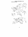
TO REMOVE MOWER
Mower will be easier to remove from the
right side of tractor.
1. Place attachment clutch in "DISENGAGED" position.
2, Move attachment lift lever forward to
lower mower to its lowest position•
3. Roll belt off engine pulley.
4. Remove small retainer spring, and lift
clutch spring off pulley bolt•
5. Remove large retainer spring, slide
• collar off and push housing guide out
of bracket.
6. Disconnect anti-swaybar from chassis
bracket by removing retainer spring.
7, Disconnect suspension arms from
rear deck brackets by removing
retainer spdngs,
8. Disconnect front links from deck by
removing retainer springs.
9. Raise lift lever to raise suspension
arms. Slide mower out from under
tractor,
IMPORTANT: If an attachment other than
the mower deck is to be mounted on the
tractor, remove the front links and hook
the clutch spring Into square hole in
frame.
TO INSTALL MOWER
1. Raise attachment lift lever to its
highest position•
2. Slide mower under tractor with
discharge guard to right side of tractor.
3. Lower lift lever to its lowest position.
4. Install mower in reverse order of
removal instructions.
TO LEVEL MOWER HOUSING
Ad ust the mower while tractor is parked
on level ground or driveway. Make sure
tires are propedy inflated (See "PRODUCT SPECIFICATIONS" section of this
manual). If tires are over or
undednflated, you will not propedy adjust
your mower.
Small RetainerSpring
Clutch
Link
Anti-Sway
Collar
Housing Guide
Large
Spring
23
SIDE-TO-SIDE ADJUSTMENT
• Raise mower to its highest position,
• At the midpoint of both sides of mower,
measure height from bottom edge of
mower to ground. Distance =A" on
both sides of mower should be the
same or within 1/4" of each other.
• If adjustment is necessary, make
adjustment on one side of mower only.
• To raise one side of mower, tighten lift
link adjustment nut on that side.
• To lower one side of mower, loosen lift
link adjustment nut on that side.
NOTE: Each full turn of adjustment nut
will change mower height about 1/8".
• Recheck measurements after adjusting.
Bottomedge of
• To raise front of mower, loosen nut "F"
from trunnion on both front links.
Tighten nut "E" on both front links an
equal number of turns.
• When distance "D" is 1/8" to 1/2" lower
at front than rear, tighten nut "F" against
trunnion on both front links.
• Recheck side-to-side adjustment.
_'_/_/'_/_
M and rel
BothFront LinksShouldbe Equal in Length
Bottomedge of
Nut ._Nut
"E"
Suspension Arm
Lift Unk
Adjustment
"_
Trunnion_
Nut ----"--"
FRONT-TO-BACK ADJUSTMENT
IMPORTANT: Deck must be level side-to
side. If the following front-to-beck adjustment is necessary, be sure to adjust both
front links equally so mower will stay level
side-to-side.
To obtain the best cutting results, the
mower housing should be adjusted so
that the front is approximately 1/8" to 1/2"
lower than the rear when the mower is in
its highest position.
Check adjustment on right side of tractor.
Measure distance "D" directly in front and
behind the mandrel at bottom edge of
mower housing as shown.
• Before making any necessary adjustments, check that both front links are
equal in length. Both links should be
approximately 10-3/8'.
• If links are not equal in length, adjust
one link to same length as other link.
• To lower front of mower loosen nut "E"
on both front links an equal number of
turns.
• When distance "D" is 1/8" to 1/2" lower
at front than rear, tighten nuts =F"
against trunnion on both front links.
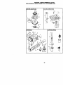
TO REPLACE MOWER BLADE DRIVE
BELT
The mower blade drive belt may be
replaced without tools. Park the tractor on
level surface. Engage parking brake.
BELT REMOVAL 1. Remove mower from tractor (See "TO
REMOVE MOWER" in this section of
this manual).
2. Work belt off both mandrel pulleys and
idler pulleys.
3. Pull belt away from mower.
24
BELT
INSTALLATION
4. Installnewbeltin reverseorder of
removal.
5, Make sure belt is in all pulley grooves
and insideall belt guides.
6, Installmower in reverse order of
removal instructions.
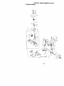
TO ADJUST BRAKE
Yourtractoris equippedwithan adjustable
brakesystemwhichis mountedon the
sideof the transaxle.
Iftractorrequiresmore than six(6) feet
stoppingdistanceat high speed in highest
gear,then brakemustbe adjusted.
1. Depressclutch/brakepedaland
engage parkingbrake.
2. Measuredistancebetween brake
operatingarm and nut "A"on brake rod.
3. If distanceisotherthan 1-9/16', loosen
jam nutand turn nut=A"untildistance
becomes1-9/16". Retightenjam nut
against nut "A".
4. Roadtest tractorfor proberstopping
distanceas statedabove. Readjustif
necessary. If stoppingdistanceis still
greaterthan six (6) feet in highestgear,
further maintenanceis necessary.
Contacta Sears or other qualified
service center.
With Perking
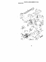
2. Remove belt from stationary idler and
clutching idler.
3. Pull belt slack toward rear of tractor.
Carefully remove belt upwards from
transmission input pulley and over
cooling fan blades.
4. Pull belt toward front of tractor and
remove downward from around
engine pulley.
5. Install new belt by reversing above
procedure.
Engine
Pulley -------ClutchingIdler_
StationanjIdler_
Transmission
Input Pulley,
C
Brake "Engaged"
TRANSAXLE MOTION CONTROL
LEVER NEUTRAL ADJUSTMENT
The motion control lever has been preset
at the factory and adjustment should not
be necessary.
1. Loosen adjustment bolt in front of the
right rear wheel, and lightly tighten.
2. Start engine and move motion control
lever until tractor does not move
forward or backward.
3. Hold motion control lever in that
position and tum engine off.
4. While holding motion control lever in
place, loosen the adjustment bolt.
5. Move motion control lever to the
neutral (N) (lock gate) position,
6. Tighten adjustment bolt securely.
NOTE: If additional clearance is needed
to get to adjustment bolt, move mower
deck height to the lowest position.
After above adjustment is made, if the
tractor still creeps forward or backward
while motion control lever is in neutral
position, follow these steps:
1. Loosen the adjustment bolt.
Nut
- Operating
Arm
Do Not touchthis nut. If furtherbrakeadjustment is necessary contact your nearest
authorizedservice center/department
TO REPLACE MOTION DRIVE BELT
Park the tractor on level surface. Engage
parking brake. For assistance, there is a
belt installation guide decal on bottom
side of left footrest.
1. Remove mower (See "TO REMOVE
MOWER" in this section of this
manual.)
25
2. Move the motion control lever 114 to
1/2 inch in the direction it is trying to
creep.
3. Tighten adjustment bolt securely.
4. Start engine and test.
5. If tractor still creeps, repeat above
steps until satisfied.
MotionControl
Neutral Lock Gate
Lever
TRANSMISSION
MENT
REMOVAUREPLACE-
Should your transmission require
removal for service or replacement, it
should be purged after reinstaltation and
before operating the tractor. See
=PURGE TRANSMISSION" in the
Operation section of this manual.
TO ADJUST STEERING WHEEL ALIGNMENT
if steedng wheel crossbars are not
horizontal (left to right) when wheels are
positioned straight forward, remove
steering wheel and reassemble per
instructions in the Assembly section of
this manual.
FRONT WHEEL TOE-IN/CAMBER
The front wheel toe-in and camber are
not adjustable on your tractor. If damage
has occurred to affect the front wheel toein or camber, contact a Sears or other
qualified service center.
TO REMOVE WHEEL FOR REPAIRS
1. Block up axle securely.
2. Remove axle cover, retaining ring and
washers to allow wheel removal (rear
wheel contains a square key - Do not
lose).
3. Repair tire and reassemble.
NOTE: On rear wheels only: align
grooves in roar wheel hub and axle.
Insert square key.
4. Replace washers and snap retaining
ring securely in axle groove.
5. Replace axle cover.
NOTE: TO sea_ tire punctures and prevent.
flat tires due to slow leaks, tire sealant
may be purchased from your local parts
dealer. Tire sealant also prevents tire dry
rot and corrosion.
Washers
Retaining _
__
Ring\ /\ ff" ll
Axle
\
I \
El{
{( ,'_ "t_
Square Key /(Rear Wheel Only)
TO START ENGINE WITH A WEAK
BATTERY
_,
Au'noN: Lea.d-acidbatteries gece=
explssive gases..,eep sparks, flam_ anc
smoking materialsaway from batteries.
Always wear eye protectionwhen arourK
batteries.
if yourbattery is too w_ak to startthe engi_
shouldbe recharged. (See "BATI'ERY" in
MAINTENANCE section of thismanual).
If "jumper cables"are used for emergent
_,
followth:_sprocedure:
IMPORTANT: Yourtractoris equippedwf
12 voltnegative groundedsystem. The ol
vshicel must also be a 12 volt negative
grounded system. Do not use your tractor
batteryto stad other vehicles.
TO A'N'ACH JUMPER CABLES 1. Connect each end of the RED cab
the POSITIVE (+) terminal of each
battery, taking care not to short
against chassis.
2. Connect one end of the BLACK c_
to the NEGATIVE (-) terminal of ful
charged battery.
3. Connect the other end of the SLAC
cable to good CHASSIS GROUND
away from fuel tank and battery.
TO REMOVE CABLES, REVERSE ORDI
1. BLACK cable first from chassis an(
then from the fully charged battery.
2. RED cable last from both batteries.
Charg
"re
26
Termil
REPLACING
BA'R'ERY
tc_rmCAUTIQN:
.,Do
notshortbaltery
inals oy allowing a wrencn or any
other object to contact both terminals at
the same time. Before connecting battery,
remove metal bracelets, wdstwatch
bands, rings, etc.
Positive terminal must be connected first
to prevent sparking from accidental
grounding.
1. Lift seat pan to raised position and
open battery box door.
2. Disconnect BLACK battery cable first
then RED battery cable and carefully
remove battery from tractor.
3. Install new battery with terminals in
same position as old battery.
4. First connect RED battery cable to
positive (+) terminal with hex bolt and
keps nut as shown. Tighten securely.
5. Connect BLACK grounding cable to
negative (-) terminal with remaining
hex bolt and keps nut. Tighten
securely.
6. Close battery box door.
TO REPLACE FUSE
Replace with 20 amp automotive-type
plug-in fuse. The fuse holder is located
behind the dash.
TO REMOVE HOOD AND GRILL ASSEMBLY
1. Raise hood.
2. Unsnap headlight wire connector.
3. Stand in front of tractor. Grasp hood at
sides, tilt toward engine and lift off of
tractor.
4. To replace, reverse above procedure.
Hood
HeadlightWire
Connector
ENGINE
Battery
Box
Keps Nut----_.
x Bolt
Positive (Red) Cable
Negative (Block) Cable
TO REPLACE HEADLIGHT BULB
1. Raise hood.
2. Pull bulb holder out of the hole in the
backside of the grill.
3. Replace bulb in holder and push bulb
holder securely back into the hole in
the backside of the grill.
4. Close hood.
INTERLOCKS AND BELAYS
Loose or damaged widng may cause your
tractor to run poody, stop running, or
prevent it from starling.
• Check wiring. See electrical widng
diagram in the Repair Parts section.
Maintenance, repair,or replacementof
emissioncontrol devices and systems,which
are beingdone at the custon'rersexpense,
may be performed by any non-roadengine
repair establishmentor individual.Warranty
repairs must be performed by an authorized
engine manufactursfs sen,ice outlet.
TO ADJUST THROTTLE CONTROL
CABLE
The throttlecontrolhas been preset at the
factoryand adjustmentshouldnot be
necassery.Check a_ustrnent as described
below before looseningcable. If adjustmentis
necessary, proceed as follows:
1. With engine not running,move throttle
controllever from slow to choke position.
Slowlymove lever from choke to fast
position.
2. Check to see if hole in throttla laver and
hole in spsed controlbracket are aligned.
3. If holes are not aligned, loosencable
clamp screw and _dignthe holes by
insertinga pencil or a 1/4" driUbit through
both holes.
4. Pull throttle cable up to remove slack and
tightencable clamp screw. Remove
alignment pencil or ddll bit.
27
TO ADJUST
CARBURETOR
The carburetorhas been preset at the factory
and adjustmentshould not be necessary.
However, minor adjustmentmay be required
to compensate for differencesin fuel,
temperature, altitudeor load. If the carburetor
does need adjustment, proceed as follows:
In general, fuming the adjustingneedles In
(clockwise) decreases the supply of fuel to
the engine giving a leaner fueVair mixture.
Tuming the adjustingneedles out (counterclockwise)increases the supplyof fuelto the
engine giving a richerfuel/air mixture.
IMPORTANT: Damage to the needles and
seats in carburetor may result iffumed in too
tight.
NOTE: The carburetor on this engine is low
emission. It is equipped with an idle fuel
adjustingneedle with a limiter cap, which
allows some adjustmentwithin the limits
allowed by the cap. Do not attempt to remove
the limitercap. The limitercap cannot be
removed withoutbrealdng the adjusting
needle.
1. Be sure you have a clean air filterand the
throttle controlcal0_ is adjusted properly
(see above).
2. Start engine and allow to warm for five
minutes. Make adjustments with engine
runningand shift/motioncontrol lever in
neutral (N) position.
3. Idtesceed eaffin_o- W'dhthrottle control
lever in slow position,engine should idle
at 1750 RPM. If engine idlestoo slow or
fast, turn idle ,speedadjustingscrew in or
out untilcorrect idle is attained.
4. Idle fuel needle setting- With threttle
control lever in slow position,turn idle fuel
adjustment needle in (clockwise) until
engine begins to die and than turn out
(counterclockwise)until engine runs
rough.Turn needle to a point midway
_n
those two positions.
5. Recheck idle speed. Readjust if necassaP/.
ACCELERATION TEST 6. Move throttle control lever fromslow to
fast position.If engine hesitates or dies,
tum idle fuel adjustingneedle out
(counterclockwise)1/8 fum. Repeat test
and continue to adjust,if necessary, until
engine acceleretes smoothly.
High speed stop is factory adjusted. Do
not adjust - damage may result.
IMPORTANT: Never tamper with the
engine governor, which is factory set for
proper engine speed. Overspeeding the
engine above the factory high speed
setting can be dangerous. If you think the
engine-governed high speed needs
adjusting, contact a Sears or other qualified
service center, which has proper equipment and experience to make any
necessary adjustments.
Cable
Clamp -_.
Screw
Speed Control
Idle Speed
Adjusting_
I
screw
Idle Fuel
Adjusting_
28
IJ_
_'_J
_
!
Immediately prepare your tractor for
storage at the end of the season or if the
tractor will not be used for 30 days or
more.
,_ CAUTION: Never store the tractor
with gasoline in the tank inside a building
where fumes may reach an open flame or
spark. Allow the engine to cool before
storing in any enclosure.
TRACTOR
Remove mower from tractor for winter
storage. When mower is to be stored for
a period of time, clean it thoroughly,
remove all dirt, grease, leaves, etc. Store
in a clean, dry area.
1. Clean entire tractor (See "CLEANING"
in the Maintenance section of this
manual).
2. Inspect and replace belts, if necessary
(See belt replacement instructions in
the Service and Adjustments section
of this manual).
3. Lubricate as shown in the Maintenance section of this manual.
4. Be sure that all nuts, bolts and screws
are securely fastened. Inspect moving
parts for damage, breakage and wear.
Replace if necessary.
5. Touch up all rusted or chipped paint
surfaces; sand lightly before painting.
BAI-rERY
• Fully charge the battery for storage.
• After a period of time in storage, battery
may require recharging.
• To help prevent corrosion and power
leakage during long periods of storage,
battery cables should be disconnected
and battery cleaned thoroughly (see
"TO CLEAN BATTERY AND TERMINALS" in the Maintenance section of
this manual).
• After cleaning, leave cables disconnected and place cables where they
cannot come in contact with battery
terminals.
• If battery is removed from tractor for
storage, do not store battery directly on
concrete or damp surfaces.
Also, experiance indicates that alcohol
blended fuels (called gasohol or using
ethanol or methanol) can attract moisture
which leads to separation and formation
of acids dudng storage. Acidic gas can
damage the fuel system of and engine
while in storage.
1. Drain the fuel tank.
2. Start the engine and let it run until the
fuel lines and carburetor are empty.
• Never use engine or carburetor cleaner
products in the fuel tank or permanent
damage may occur.
• Use fresh fuel next season.
NOTE: Fuel stabilizer is an acceptable
alternative in minimizing the formation of
fuel gum deposits during storage. Add
stabilizer to gasoline in fuel tank or
storage container. Always follow the mix
ratio found on stabilizer container. Run
engine at least !0 minutes after adding
stabilizer to allow the stabilizer to reach
the carburetor. Do not drain the gas tank
and carburetor if using fuel stabilizer.
ENGINE OIL
Drain oil (with engine warm) and replace
with clean engine oil. (See "ENGINE" in
the Maintenance section of this manual).
CYLINDER(S)
1. Remove spark plug(s).
2. Pour one ounce of oil through spark
plug hole(s) into cylinder(s).
3, Tum ignition key to "START" position
for a few seconds to distribute oil.
4. Replace with new spark plug(s).
OTHER
• Do not store gasoline from one season
to another.
• Replace your gasoline can if your can
starts to rust. Rust and/or dirt in your
gasoline will cause problems.
• If possible, store your tractor indoors
and cover it to give protection from dust
and dirt.
• Cover your tractor with a suitable
protective cover that does not retain
moisture. Do not use plastic. Plastic
cannot breathe which allows condensation to form and will cause your
tractor to rust.
IMPORTANT:
Never cover tractor while
engine and exhaust areas are still warm.
ENGINE
FUEL SYSTEM
IMPORTANT: It is important to prevent
gum deposites from forming in essential
fuel system parts such as carburetor, fuel
hose, or tank during storage.
29
TROUBLESHOOTING CHART
PROBLEM
Will not start
CAUSE
CORRECTION
1. Fill fuel tank.
2. See =TOSTART ENGINE"
properly.
in Operationsection.
3. Engine flooded,
3. Wait several minutesbefore
attemptingto start.
4. Bad spark plug.
4. Replace spark plug.
5. Dirty air filter.
5. Clean/replaceair filter.
6. Dirtyfuel filter.
6. Replace fuel filter.
7. Water in fuel.
7. Drain fuel tank and carbure
tor, refilltank withfresh
gasolineand replace fuel
filter.
8. Loose or damaged wiring. 8. Check all wiring.
9. Carburetorout of adjustment.9. See =ToAdjustCarburetor"
in Service Adjustments
section.
t0.Contact a Sears or other
10.Engine valves out of
adjustment.
qualifiedservice center.
1. Out of fuel,
2. Engine not "CHOKED"
Hard to start
1.
2.
3.
4.
5.
Enginewlll not
turn over
1. Clutch/brake pedal not
depressed
2, Attachment clutch is
engaged.
3. Weak or dead battery.
4. Blown fuse,
5. Corroded battery terminals.
6. Loose or damaged wiring.
7. Faulty ignition switch.
Dirtyair rifler.
Bad spark plug.
Weak or dead battery.
Dirtyfuel filter.
Stale or dirtyfuel.
1.
2.
3.
4.
5.
Clean/replace air filter.
Replace spark plug.
Recharge or replace battery.
Replacefuel filter.
Drain fuel tank and refillwith
fresh gasoline.
6. Check all widng.
6, Loose or damaged wiring.
7. Carburetor out of adjustment. 7. See =ToAdjustCarburetor"in
Service Adjustments
section.
3. Contacta Sears or other
8. Enginevalves out of
adjustment.
qualified service center.
1. Depress clutch/brake pedal,
9. Faulty operatorpresence
switch(es).
2. Disengage attachment
clutch.
3. Recharge or replace battery.
4. Replace fuse.
5. Clean battery terminals.
6. Check all wiring.
7. Check/replace ignition
switch.
8. Check/replace solenoid or
starter.
9. Contact a Sears or other
qualified service center.
Engine clicks but
will not start
1.
2.
3.
4.
1.
2.
3.
4.
Loss of power
1. Cutting too much grass/too
fast.
2. Throttlein "CHOKE"
position.
3O
8. Faultysolenoidor starter.
Weak or dead battery.
Corroded battery terminals.
Loose or damaged wiring.
Faulty solenoid or starter,
Recharge or replace battery.
Clean battery terminals.
Check all wiring.
Check/replece solenoid or
starter.
1. Set in "Higher Cut" position/
reduce speed.
2. Adjust throttle control.
TROUBLESHOOTING
CHART
PROBLEM
CAUSE
Lossofpower 3. Build-upof grass, leaves
and trash under mower.
(continued)
CORRECTION
3. Clean undersideof mower
housing.
4. Dirtyair filter.
4. Clean/replace air filter.
5. Low oil level/dirtyoil.
5. Check oil level/changeoil.
6. Faultyspark plug.
6. Clean and regap or change
spark plug.
7. Dirty fuel filter.
7. Replacefuel filter.
8. Stale or dirty fuel.
8. Drain fuel tank and refill
with fresh gasoline.
9. Water in fuel.
9. Drain fuel tank and
carburetor,refilltank with
fresh gasoline and replace
fuel filter.
10.Spark plug wire loose.
10.Connect and tightenspark
plug wire.
11.Dirtyengine air screen/fins. 11.Clean engine air screen/
fins.
12.Dirty/cloggedmuffler.
12.Clean/replace muffler.
t3.Loose or damaged widng. 13.Check all wiring.
14.Carburetor out of
14.See "To Adjust Carburetor"
adjustment.
in Service Adjustments
section.
15.Enginevalves out of
15.Contacta Sears or other
adjustment.
qualified service center.
Excessive
vibration
1. Worn, bent or loose blade.
2. Bent blade mandrel.
3. Loose/damagedpart(s).
I.
Replace blade.
Tighten blade bolt.
2. Replace blade mandrel.
3. Tighten loose part(s).
Replace damaged parts.
Enginccontinuea
to run when
operator leaves
seat with
attachment
clutch engaged
1. Faulty operator-safety
presence control system,
1. Check wiring, switches and
connections. If not corrected
contact a Sears or other
qualified service center.
Poor cut - uneven
I. Worn, bent or loose blade.
1. Replace blade. Tighten
blade bolt.
2. Level mower deck.
3. Clean underside of mower
housing.
4. Replace blade mandrel.
5. Clean around mandrels to
open vent holes.
2. Mower deck not level.
3. Buildupof grass, leaves,
and trash under mower.
4. Bent blade mandrel.
5. Clogged mower deck vent
from build-upof grass,
leaves, and trash around
mandrels.
Mower blades will
not rotate
1. Obstruction in clutch
mechanism.
2. Worn/damaged mower
drive belt.
3. Frozen idler pulley.
4. Frozen blade mandrel.
31
1. Remove obstruction.
2. Replace mower drive belt.
3. Replace idler pulley.
4. Replace blade mandrel.
TROUBLESHOOTING
PROBLEM
Poor grass
dieH_harge
CHART
CAUSE
CORREC_ON
1. Place throttle control in
"FAST" position.
2. Travel speed too fast.
2. Shift to slower speed.
=3. Wet grass.
3. Allow grass to dry before
mowing.
!4. Mower deck not level.
4, Level mower deck.
15. Low/uneventire air pressure 5, Check tires for proper air
pressure.
6. Worn, bent or looseblade. 6. Replace/sharpen blade.
Tighten blade bolt.
7. Clean underside of mower
7. Buildupof
grass,
leaves
and
trash under mower.
housing.
_. Mower drive belt worn.
8. Replace mower drive belt.
9. Blades improperlyinstalled. 19. Reinstall blades sharp edge
down.
10. Improperblades used.
10. Replace with blades listed
in this manual.
11.Clogged mower deck vent 11.Clean around mandrels to
holes from buildupof
open vent holes,
1. Engine speed too slow.
grass, leaves, and trash
around mandrels.
Headlight(s) not
working
(if so equipped)
1.
2.
3.
4.
Switchis"OFF".
Bulb(s) burnedout.
Faultylightswitch.
Looseor damaged wiring.
5. Blown fuse.
Battery will not
charge
1, Bad batten/cell(s).
2. Poor cable connections.
3. Faultyregulator
I11 Turnswitch"ON".
Replace bulb(s).
13. Checldreplacelight switch.
4. Check wiringand connections.
5. Replace fuse.
1. Replace battery.
2. Check/clean all conneclions.
3. Replace regulator.
(if so equipped).
Loss of drive
Engine "bacMIrae"
when turning
engine
"OFF"
4. Faultyalternator.
4. Replace alternator.
1. Freewheel control in
=disengaged" position.
2. Motion ddve belt worn,
damaged, or broken.
3. Air trapped in transmission
during, shipment or
servicing.
1. Place freewheelcontrolin
=engaged" position.
2. Replace motiondrive belt.
1. Engine throttlecontrol not
1. Move throttlecontrolto
"SLOW"positionand allow
to idle for 30 secondsbefore
stopping engine.
set at =SLOW"
positionfor 30 seconds
before stoppingengine.
32
3. Purge transmission.
SCHEMATIC
IGNITION
SWITCH
CIRCUIT
OFF
TRACTOR
--MODELNUMBER
917.271064
M,p_._.A1
'_IAKE"
I it
_=_
NON-REMOVABLE
CONNECTIONS
ii I
REMOVABLE
CONNECTIONS
NONE
RUN/I-IGHT
B÷AI
A2_.
START
RUN
B ÷B_.AI
S + A1
NONE
NONE
RELAY
WIRING INSULATED CUP8
NOTE: IF WIRING INSULATED CLIPS WERE REMOVED FOR
SERVICING OF UNIT, THEY SHOULD BE REPLACED TO
PROPERLY SECURE YOUR WIRING.
33
TRACTOR - - MODEL NUMBER 917.271064
ELECTRICAL
I t
t /
34
TRACTOR - - MODEL NUMBER 917.271064
ELECTRICAL
KEY
NO.
I
2
8
16
21
22
24
25
26
27
28
29
30
33
40
41
42
43
45
52
81
PART
NO.
163465
74760412
156417
161343
166182
4152J
4799J
146147
175158
73510400
4207J
160784
175566
140403
17_219
71110406
131563
175141
122822X
141940
109748X
DESCRIPTION
Battery 12 Volt 28 Amp
Bolt, Hex Head 114-20 unc x 3/4
Case, Battery Mech Hinge
Switch, |ntedock N OpeN Oton
Harness, Light Socket (includes 4152J)
Bulb, Light
Cable, Battery, 6 Gauge, Red, 11"
Cable, Battery, 6 Gauge, Red, W/16 Wire
Fuse
Nut Keps Hexl/4.20 Unc
Cable, Ground, 6 Gauge, Black, 12"
Switch, Plunger Normal Op Olive
Switch, Ignition
Key, Ignition
Harness, Ignition
Bolt, Hex Heed, Rn. 114-20 x 1i2
Cover, Terminal, Red
Solenoid
Ammeter Rectangular
protection Wire Loop
RaleyAsm,
NOTE: Allcomponentdimensionsgiven In U.S. inches
1 inch==25,4 mm
35
TRACTOR - - MODEL NUMBER 917.271064
CHASSIS AND ENCLOSURES
208
11""_-
_
54
1
74
TRACTOR - - MODEL NUMBER 917.271064
CHASSIS AND ENCLOSURES
KEY PART
NO. NO,
1
2
3
5
9
10
11
12
13
17
18
25
26
28
29
30
31
37
38
51
52
53
54
55
57
58
60
64
74
142
t43
144
145
206
207
208
212
- NOTE:
169830
16_061
17660612
155272
168337X013
STD533710
155927
145660
172107X010
144983X558
126938X
19131312
ST(To41437
156725X558
155217X599
164918X558
139976
1749_08
169834
73800400
19091416
145201
161464
145202
STD522507
150127
72140606
154798
73680600
165867
154966
154207
156524
170165
1767C608
17670608
165919
5479J
DESCRIPTION
Cttassis Stamping
Drav.Oar
Screw 3/_16 x 3/4
Bumper Hood/Dash
Dash
Bolt, Carriage 3_-16 x 1
Panel, Dash, L.H.
Clip "rinnerman G dl_eP/L
Pane_, Dash, R.H.
Hood Assembly
Bumper Hood
Washer 13/32 x 13/16 x 12 Gauge
Nut
GdfleLensAsm
Ler_, Gdlle
Fend/Ftrest Pnt STLT
Bracket, Fender Suppod
Screw Thdrol 5/16-18 x 1/2 Tyt
Bracket Asm. Pivot Mower Rear
Nut Lock w/Insert 1/4-20 UNC
Washer 9/32 x 7/8 x 16 Ga.
Bracket Gdlle Plckoff LH
Screw Hex Wshd 8-18 x 7/8
Bracket Gdlle Ptckoff RH
Bolt, Fin He)( 1/4-20 UNC x .75
Duct Air Engine P/I- LT
Bolt Rdhd Sqnk 3/8-16 UNC x 3/4
Dash Lower STLT
Nut Crownlock 3/8-16 UNC
Plate Reinforcement STLT
Bracket Swaybar Chassis
Bracket Pnt Footrest STLT
RJod Pivot Chassis/Hood
Bolt ShoulderS/16-18TT
ScrewThdrol 5/16-18xl/2TYTT
Screw Thdrol 3/8-16 x 1/2
Insert Lens Reflec_ve
Plug, Button
All component dimensions given In U.S. inches
1 inch = 25.4 mm
37
TRACTOR - - MODEL NUMBER 917.271064
GROUND DRIVE
36
38
TRACTOR - - MODEL NUMBER 917.271064
GROUND DRIVE
KEY PART
NO. NO,
1
......
8
10
!4
15
16
19
21
22
24
25
26
27
28
29
3O
3_
34
35
36
37
38
39
40
41
42
47
48
49
50
51
52
53
55
56
57
59
61
62
63
64
65
165866
S'rD561210
10040400
7449(To44
ST[To41431
STD541437
130564
169498
73350600
106888X
S'rD551037
STD561210
145204
71673
169592
7476(_12
15.5071
120183X
19211615
1572H
131494
74760644
4470J
165838
19131312
127783
154407
123205X
ST[To23715
s'r[To41437
STD541431
105710X
105709X
ST[To23712
140294
16_691
17060612
8883R
140186
71170764
s'rD551143
DESCRIPllON
Transaxle (See Breakdown)
Hydro Gr 314-0510
Rod Sldlt Fender Adjust
PInCotter 1/8xl CAD
Washer Lock Hvy Helicel
Bolt Hex FLGHD 5/16-18 x Gr 5
Nut Lock Hex W/fns. 5/16-18 Unc
NutLockHexW/Wsh
3/8-16Unc
Knob, Deluxe 1/2.13
Rod, Brake Hydro
Nut, Hex Jam 3/8-16 Unc
Spring, Brake Rod
Washer
Pin Cotter 1/8 x 3/4 CAD.
Rod, Paddng Brake
Cap, Parking Brake
Bracket, Transaxle
Bolt Hex Hd 5/16-18 Unc x 3/4
Shaft, FOOt Pedal
Bearing, Nyton
Washer
Pin, Roll
Polley, Idler, Flat
Bolt
Spacer, Split
Keeper, Belt _dler
Washer 13/82 x13/16 x12 Gauge
Pulley, I_er, V-Groove
Be,crank, Clutch
Retainer, Belt
Bolt
NutCrownlock 3/8-16UNC
Nut, Crownlock 5/16-18Unc
Link.ClutCh
Spring, Retum, Clutch
Bolt Hex 3/8-16 x 1-1/4
V-Be_t
Keeper, Center Span
Screw. 3/8-16 x 3/4
Cover, Pedal
Putley, Engine
Boft Hex 7/16-20 x 4 Gr. 5
Washer
KEY
NO,
PART
NO.
DESCRIPllON
66
70
71
72
73
74
75
76
77
78
81
82
83
84
89
90
g5
g6
116
120
150
151
156
158
159
161
162
163
164
165
166
168
169
197
198
199
200
2G2
154778
134683
169183
19132012
169182
137G57
12!749X
STD581075
123583X
121748X
165596
165711
19171216
169594
1648SOX428
124346X
170201
4497H
72110610
73900600
165850
19133210
166002
165589
165494
72140406
73680400
74780416
19091010
16.5623
166880
165492
165580
169613
169593
169612
7214050_
72110612
Keeper Belt Engine Hydro
Keeper Belt Engine
Strap Torque Lh Hydro
Washer 13/82 x1-1/4 x12 Gauge
Strap Torque Rh Hydro
Spacer, Axle
Washer 25/82 x 1-1/4 x 16 Gauge
E-F_
Key, Square
Washer 25/32 x 1-5/8 x 16 Gauge
Shatt Asm Cross Tapered
Spdng Torsion
Washer 17/82x3!4x16Ga.
LInkTransaxle
Console. Shift
Nut Self-Thd Wsh-hd 1/4 Zinc
Control Bypass Hydro 20' Tires
Retainer Spdng 1" Zinc/Cad
Bolt Rdhd Sqneck 3/8-16 x 1.25
Nut Lock Rg. 3/8ot6 Unc
Bushing Bellcrank Grd Ddve
Washer 13/32 x 2 x 10 Ga.
Washer Srrted 5/161D x 1.125
Bracket Sh_ft Mount
Hub Tapered Flange Sl_ft Lt
Bolt Rdhd Sqnk 1/4-20 x 3/4 Gr 5
NutCrownlOOkl/4-20Unc
Bolt Hex Fin 1/4-20 Unc x 1 Gr 5
Washer 5/8 x .281 x 10 Ga
Bracket Pivot Lever
Screw5/16-18xS/8
BoltShoulder5/16*18x.561
PlateFasten_ng
Nyllner Snap-ln5/8"lD
Washer Nyl 7/8 ID x .105" Hyd
Bolt Shoaider5/16-18UNC
BoltRdhdSgnkS/16-18UNC
xl
Bolt Carr Sh 3/8-16 x 1-1F2 Gr.5
NOTE: All oompenent dimensions given in U.S. inches
1 inch = 25.4 mm
39
TRACTOR - - MODEL NUMBER 917.271064
STEERING ASSEMBLY
_41
47
40
TRACTOR-STEERING ASSEMBLY
MODEL NUMBER 917.271064
KEy PART
NO. NO.
DESCRIPTION
1
2
3
4
5
6
7
8
9
10
11
13
15
17
18
19
22
23
25
26
27
28
29
30
3_
36
37
38
39
40
41
42
43
44
46
47
51
54
62
63
65
66
67
68
79
80
82
85
Steering Wheel
Axle Assembly STMP Dropped STL
Spindle Assembly, L.H.
Spindle Assembly, R.H,
Beating, Race, Thrust, Hardened
Washer 25/32 x 1-5/8 x 16 Gauge
Washer 27/32 x 1-1/4 x 16 Gauge
Ring, KHp
Beadng, Steedng Column
Dragitnk
Washer, Lock
Spacer Brg Axle Front
Nut, Hexllange Lock
Shaft Assembly, Steedng
Washer, Thrust .515 x .750 x .033
Support, Shaft
Screw Hex Wshhd Torx
Pittman Shaft Assembly
Bracket, Steering
Bushing, Unk, Drag
Gear, Sector
Washer 13/82 x 7/8 x 16 Gauge
Screw 3/8-16 x 3/4
Pin
Rod, Tie
Bushing, Steedng
Screw
Insert, Steedng Wheel
Washer 13/32 x 2-3/8 x 12 Gauge
Nut LockCenter3!8-24UNF
Adaptor, Steedng Wheel
Boot, Steedng Shaft
Washer 25/32 x 1-1/4 x 16 Gauge
Extension Shaft Steedng LR.LT
Cap,Spindle
Fitting, Grease
Nut Lock Hex w/ins. 5/16-18 UNC
Bolt Fin Hex 5/16-18 UNC x 1-1/4
Kit Steedng Asm Service
Bolt, Fin Hex 3_-16 UNC x 1Gr 5
Spacer Brace Axle
Beadng Arm Pi6man
Bblt Rdhd Sqnk 3/8-16 x 2-1/4
Axle, Brace
Washer 13/32 x 1-1/4 x 12 Ga
Bolt Hex Nylon 3/8-16 x 3/4
Bracket Susp Chassis Front
Fastner Christmas Tree
139768
154427
168_10
169839
62_6H
121748X
19272016
12000(_9
3366R
169832
S_1137
136518
145212
156546
57079
160395
165857
165851
154406
126847X
136874
19131416
17060612
STD561210
130465
155099
152927
139769
19133812
STD541537
100711L
145054x428
121749X
153720
121232X
6855M
ST_o41431
74780520
16790_
STD523710
160367
154404
72140618
169827
19132012
74950612
169835
133835
NOTE: All component dimensions given in U.S. inches
1 inch = 25.4 mm
41
TRACTOR "" MODEL NUMBER 917.271964
ENGINE
• • , ,'_•
14
>105
42
. ••
i_
TRACTOR - - MODEL NUMBER 917.271064
ENGINE
KEY
NO.
PART
NO.
DESCRIPTION
I
2
3
4
13
14
16
23
29
31
17(T048
17720410
......
159420
12-041-o3
148456
STD551237
169837
137180
1092(_X
1589S0
123487X
137040
148315
124028X
17670412
170(X_12
19091416
19101216
7476(To0_
73510400
M73030600
17120616
Conbol, ThrOttlelChoke
Screw, Hex Head, Thread Cutting 114-20 x 51
8
Engine, (See Breakdown) Kohler Model NO. CV15-41598
Muffler
Gasket Kobler
Tube Drain Oil Easy
Washer
Shield BrrvObr Guard
Arrestor, Spark
Tank, Fuel
Cap Assemely, Fuel Seam, Vented
Clamp, Ho_e
Line, Fuel
Plug Dreln Oil Easy
BuShing, Snap, Fuel Une
Screw, Hex Washer Head, TIKI., Roll. 1/4-20 x 3/4
Screw Hex Wsh Thdr 3/8-16 x 3/4
Washer 9/32 x 7/8 x 16 Gauge
Washer 5/16 x 3/4 x 16 Ga.
Belt Hex Hd 5/16-18 Unc x 1/2
Nut Kep6 Hex 1/4-20Unc
NutFlan-geM8-1.25Non-Lk71nc
Screw 3/8-16 x I
33
37
38
40
44
45
46
77
80
81
101
1(_5
NOTE:
All component dimensions given in U.S. inches
1 Inch = 25.4 mm
43
TRACTOR--MODELNUMBER
917.271064
SEATASSEMBLY
KEY PART
NO. NO.
DESCRIPTION
1
2
3
4
5
6
7
8
9
10
11
12
Seat
Bracket, Pivot, Seat
Bolt
Washer 13/32x I x 10Gange
Clip, Push-In Hinged
Nut
Spring, Seat
Screw 3/8-16x1-t/2
Washer 13/32 x 1 x 14 Gauge
Pan, Seat Emboea QCK Conn.
Kf'_t) Se;_t
Bracket, Switch Mounting
140123
140551
71110616
19131610
145006
S_1437
124181X
17000616
19131614
155_.5
166369
121246X
KEY PART
NO. NO.
13
14
15
16
17
21
22
24
DESCRIPTION
Bushing, Snap
Bo_t, carriage 1/4-20 x 1-1/2
Spacer, Split .28 x .88
Spdng
LOcknut, Flange 1/4 Grade 5
Bolt, Shoulder 5/16-18 UNC
Nut
Washer 17/32x 1-3/16x 12
Ga.
25
127018X
B_t, Shoulder 5/16-18 x .62
NOTE: Ati component dimensions given in U.S. inches
1 inch = 25.4 mm
44
121248X
72050412
134300
121250X
123976X
171852
STD541431
19171912
TRACTOR - - MODEL NUMBER 917.271064
DECALS
16
2O
KEY PART
NO. NO.
1
3
4
5
6
8
9
10
12
13
156811
1716_
171699
171763
13,3644
166887
163204
156439
146046
163261
DESCRIPTION
Decal, Oper. Instr.
Decal, Hood, R.H.
Decal, Hood, L.H.
Decal Hood Replacement
Decal, Customer Mainterlance
Decal, Deck EZ3
Decal, Fender, Craftsman
D6cal, Fender Danger
Decal, V-Bait Drive Schematic
Decal, Dash Pal
KEY PART
NO. NO.
DESCRIPTION
14
16
20
21
.--.---
Decal, V-Be_t Schematic
Decal, Battery Diehard
Decal, Better/Dngr/Psn
Eng
Decal, Fender Auto Sears
Deual, Lift Handle
Pad Footrest LH STLT
Pad Footrest RH STLT
De_al By Pass LT Hydro
Owner's Manual, English
Owner's Manual, Spanish
160396
138047
149516
163205
138311
165800X428
165799X428
169210
177558
177559
KEY PART
NO. NO.
YHEELS &TIRES
11
1
2
3
4
59"i92
65139
106222X
59904
5
6
7
8
9
10
106732X427
278H
904G-I
106106X427
122062X
7152J
11
- -
104757X428
144334
NOTE:
U.S.
45
DESCRIPTION
Valve Cap, Tire
Stem, Valve
Tire, Front
Tube, Front Tire
(Not Provided, Ser,Ace Item Only)
Rim, Front
Firing, Grease (Frcnt Wheel Only)
Beadng, Flange (Front Wheel Only)
Rim,Rear
Tire, Rear
Tube, Rear Tire
(Not Provided, Service Item Only)
Cap, Axle
Sealant, Tire 10 oz.
Allcomponentdimensionsgivenin
InchesI inch: 25.4 mm
TRACTOR -- MODEL NUMBER 917.271064
LIFT ASSEMBLY
I
/
6
20
46
15
%_,_
/
/
5
161_71_ 2_-_
TRACTOR--
MODEL NUMBER 917.271064
LIFT ASSEMBLY
KEY PART
NO. NO.
1
2
3
4
5
6
7
8
11
12
13
15
16
17
18
19
20
31
NOTE:
159460
159471
105767X
12000(X_
19211621
120183X
125631X
122365X
139665
13_66
STD6240_
173288
73350800
130171
73800800
139868
163552
169865
73540600
DESCRIPTION
Uft Lever Inner Wire Assembly
Shaft Assembly, Lift
Pin, Groove
E-Ring
Washer 21/32 x I x 21 Gauge
Eeadng, Nylon
Gdp, Handle, Fluted
Button, Plunger, Red
Link, Uft, LH.
Link, Lift, R.H,
Retainer Spring
Link, Front
Nut, Hex, Jam 1/2-13 UNC
Trunnion
Locknut, Hex, with Washer Insert 1/2-13 UNC
Arm, Suspension, Rear
Retsiner Spring
Beadng, Pvt, Lift
NuL Crownlock 3/8-24
All component dimensions _ven In U.S. inches
1 inch = 25.4 rnm
47
TRACTOR
--MODELNUMBER
917.271064
MOWER
DECK
34
\
119
118
16
27
1
19
13_
10_
9_
48
TRACTOR -- MODEL NUMBER 917.271064
MOWER DECK
KEY
NO.
1
2
3
PART
NO.
DESCRIPTION
165892
STIT'_33107
135017
14
15
16
18
19
20
21
22
23
24
25
26
27
28
29
3O
31
3_
33
34
35
36
37
Mower Deck Assembly, 42"
Bolt
Bracket ASSembly,Sway Bar,
Frofit
165460
Bracket Sway Bar 38/42" Deck
S'TD_4OOa
RetsinerSpr_g
130832
Arm.Suspension, Rear
85O857
Butt,Hex 3/8_24x1.25Gr.
8
ST[T_51137
Washer, Lock
140296
Washer, Hardened
134149
Blade,Mulching
137645
Shaft Assembly, Mandra/,
Vented (Includes Key Number 12)
128774
Housing, Mandrai, Ventad
110485X
Beadng, Ball, Mandrel
140329
Stdpper, VentodMowerDeck
721465O5
Bolt, Carriage 5/16-18x5/8
132827
Butt, Shoutder
159770
Baffle, Vortex
ST[To41431
Nut Crownlock 5/16-18 UNC
134753
Stiffener Bracket
131267
Bracket, Deflector
I(Ta3O4X
Cap, Sleeve
123713X
Spd ng, Torsion, Deltector
110452X
Nut, Push
13(_68X4,?.8 SNeld, Deflector
19111016
Washer 11/32x5/8x16Ga.
131491
Rod,Hinge
157722
Screw Thdrol Washer Head
129963
Washer, Spacer
153535
Pulley, Mandrai
137266
Nut, Toplock, Flanged
$10533717
Bolt
133835
Fastner, Chdslmas Tree
131494
Pulley, Idler, Rat
ST[Ta510_7
Washer 13/32 x 13/16 x 19
4O
44
45
46
48
49
50
51
52
53
54
55
56
59
s'rD6414O7
146088
S_4(X)3
137729
133944
174284
131340
s'rD541410
139888
131845
133943
155046
165723
141043
4
5
6
8
9
10
11
13
KEY
NO.
PART
NO.
67
68
92
101
1(_
10G
104
1G5
106
111
112
113
114
115
116
117
118
119
121
129
130
149846
144959
STD541437
136420
71081010
lg061216
STD551110
13O73O
2(_9J
155197
155198
17060514
STD541431
7211(Ta04
4O_H
165746
73930600
s'rD5510G7
143723
19131312
STD523710
131
142
143
144
145
146
147
148
149
150
151
152
153
154
STD533710
165890
157109
158634
165888
171977
131335
1690_2
165898
19091216
169670
16_676
16_674
169675
155
156
157
158
159
169671
169672
169669
17720416
72140614
--
130794
--
169583
Gauge
Nut Crowrdock 5/8-16 UNC
Guard, Mandrel, L.H.
Reta_er
Screw, Thd. Rck 1/4-20x5/8
Washer, Hardened
Roller Assembly, Cam Fo/Iower
Bolt, Shoulder #10-24 Gr. 5
Locknut
Bolt, Shoulder 5/16-18 UNC
Arm Assembiy, Pad, Brake
Washer, Hardened
Am1, Idler
Spacer, Retainer
Guard, TUV Idler
NOTE:
49
DESCRIPTION
Knob Custom Ova/
V-Belt
Nut LOCk Hex w/Ins. 3/8.16 Uric
Mulcher Cover
Screw
Washer #10
Washer, Lock
Latch Assembly, Bagger
Nut, Weld
Bracket, Gauge, Wheai LH.
Bracket, Gauge, Whsel R.H.
Scrsw 5/16-18 Unc
Nut, Hex, Keps 5/16-18 UNC
Butt, Cardage 5/16UNCx1/2
Bolt, Shoulder
Wheai,Gauge
Nut, Centedock 3/8-16
Washer3iSxT/Sx14Gauge
Bracket
Washer 13/32 x 13/16 x12 Ga.
Bolt, Rn Hex 3/6-16 UNC xl
Gr. 5
Bolt,RdhdSqnk3/8-16UNCxl
Arm 6pdng Brske Mower
Bracket Arm Idler42"
Keeper Belt 42" Clutch Cable
PuUeyldlerRat
Bolt Carriage Idler
Spring Extension
Spring Return Idler
Retainer Spdng Yellow Zinc
Washer 9/32 x 3/4 x 16 Ga.
Bracket Clutch
Cable Clutch 42 In
Washer Flat 3/8" Type B
Spring Retainer
SpaceSpdngrRetanU°n
Lever
Redclutch
Screw Hex Thd Cut 1/4.20 x5/8
BodRdhdSqn
3/8-16 UNC x 1 - 3/4
M_mdrsl Assembly (Includes Key
Numbers 8-10,12-15, 31 and 3_)
Mower Deck, Con@eta (Stan_u_:l
Deck, Order Separately Mulcher
Plate and Gauge Whe_
Components, Key Nos. 101-106
and 111-12! )
AI/component dimensions g_en in U.S.ir_hes
1 klch = 25.4 mm
o
12088
,i
88
/
81
77
79
,,n
€ :
o:_
oO
mo
9OO
• rZ
m
r-
c
Z
_
W
_
",4
z,m_
m
19
73
16
124
32
93
48
58
107 "43
TRACTOR -- MODEL NUMBER 917.271064
HYDRO GEAR TRANSAXLE - - MODEL NUMBER 314-0510
KEY PART
NO. NO.
KEY PART
NO. NO.
DESCRIPTION
t
2
3
4
5
6
7
8
9
tO
170_5t
170_
170353
170354
169898
170355
170356
170357
170358
t 79059
Main Hour,
As_
Si(_ Housing, Assern_
Center Sss_on, As6embly
Swashplate, Trunin_ Machined
Block - As6embty
Sealant 10.50z
Hex Range Screw 1/4-20 X 1.25
Stud, 5/16-24 Hax Double End
Shaft, Input
Ring - Retaining
11
12
13
14
170360
169870
170361
169869
16
170362
17
18
19
23
24
27
28
29
30
31
3_
170363
170364
150771
170365
170366
170_67
170368
170369
170_70
170371
170389
33
142991
34
35
36
37
38
39
40
41
42
43
44
17(_90
170391
170392
150792
150793
150809
170393
170394
170395
170396
150797
45
46
47
48
49
170397
170_95
170999
170400
170401
Spacer
Ring - Retalnlng
Seal, Lip .67 X 1.58 X .270
Ball Brg 17ram Id X 40_nm Od
X 12mm
Hex Flange Head Screw
5/16-24X0.75
Up Seat 18 X 32 X 7
Am1, Contrst
Beadng, 30x52x13 Thrust
Chock Plug Assembly, Wallha
Shaft, Motor
Gear. Pinion. 13!
10t/48t Gear
Gear, 10t Jack.shaft
60t Bull Gear
Sleeve Seadng ,75 X 1.575 X
SleeveSeadng(Ou_0¢ard)
.75x1.750x.625
Washer,
3/4 Id X 1-1/20d
X +I3 Thk
Up Seal _
Seal
Shaft, Axle .75 X 11.39 (Key,
Shaft, Axle .75 X 16.99 (Key,
Mltor Gear (Spllned)
Miter Gear 15t (0.5 Id)
Shaft
Ring, Spiral Retaining
Pin, Jackshaft
Magnet, Ring
Spry,
Bypas_
Hydro Mtg Screw 3/8-24 X 2.5
Long
Filter
Base. Filter
Actuator, Bypass
Rod, Bypass Aatuator
Ann, Bypass
50
51
52
1702(_
t 70403
170404
53
54
55
56
57
58
170405
170406
142977
142978
150798
170407
59
60
61
62
63
170408
142883
142881
142887
170410
64
65
142892
170411
66
67
68
69
70
71
170412
170413
170414
170415
170416
170417
72
170418
73
74
75
142884
170419
170420
76
77
78
79
80
170421
t 70422
142969
142900
150778
81
82
170423
170424
83
84
85
86
87
90
90
93
107
108
161162
170425
170426
170427
170424
170429
170430
170431
17043_
170433
109
111
112
113
170434
170435
170436
170437
116
119
120
121
170438
170439
170440
170441
122
123
124
170442
170443
170444
125
126
127
128
900
170445
170446
170447
173165
166768
r
.625
R.H.)
LH.)
Retaining Ring .250 External
Seat, Up.74 t X .250 X .2-50 Tc
Flat Washer, 518 Id X 1.00d
X .05 Thk
Retsining Ring
Beadng, Center Block
Spring - Helical Compressic_
Washer
20w-50 Oil
Brake Yoke
DESCRIPTION
Rotor, Brake
Brake Puck
Puck Rate
Brake Actuating Pin
Hlhcs 1/4-20x2 W/Patch,
SpeclalFlange
Bolt, 1/4-20 X 1 W/Patch
Spacer
Spdug, Brake Arm Bias
Sq. Hd. Bott 5/t 6-24-Ribbed
Arm, Broke
Slotted Hex Nut 5/16-24
Cofter Pin 3/32 X 3/4
Compression Spring Brake
Anti-Drag
Washer, Ht .5 I.D. X 10.D. X
,032
Flat - washar 11/32 I.D. X 7/80.D
Oil Seal .625 X 1.0 X .25
Check Plug Assembly, .027,
Wss_er
Stud, 5/16-24 Fdctlon Pack
Puck, .330 X 1.50 X ,0975
Spring, Helical Comp
Spacer
Hex Lock Nut 5/16-24Unf
(Nylon _nasd)
Wedge, Fdct;on Pack
Ctip, Washer .316xl .50x.1046
(Plated)
Pin, Standard Headless
Fi_ng, 5[16 Sae 5/32 Tube
Hose, Expansion Tank
Expanston Tank
Cap - Popflet Valve
Bolt, SellTapping
10-32 X 1/2
Puck, Inner Wedge
Spring CUp. Housing Thrust
Deflector
Washer,Motor Shaft .?lidx
1.15odx,030thk
Rug, See #6
O-Ring .07 X .301 I.D.
Shield, Verll
Bracket, Support Expanston
Tank
SilicenSponge
Fan,
7tn.
Pulley
Hex Lock Nut 1/2-20 (Nylon
Insert)
Washer, Balleville
Belt Keeper
CenterSec_on-FHter-Bypass
ASSembly
Filter AsSembly
Fas - Pulley SeMce Assembly
Seal - O-Ring Kit
Kit, Expansion Tank
Transaxle Complete
NOTE: All componentdimensionsgivenin U.S, inche
1 Inch= 25.4 mm
51
TRACTOR
- - MODELNUMBER917.271064
KOHLER
ENGINE
- MODEL
NUMBER
CVIS,TYPENUMBER
41598
1-8
CRANKSHAFT
I
EXHAUSTJ
_-4
O-,
@/5
/
6
52
TRACTOR -- MODEL NUMBER 917.271064
KOHLER ENGINE - MODEL NUMBER CV15, TYPE NUMBER 41598
AIR INTAKE/FILTRATION
KEY
NO.
PART
NO.
1
2
3
4
5
25-34'_-03-S
12-096-24-S
.12.863-12-S
12-100-08.S
12-083-10-S
6
7
8
9
12-743-12-S
230046-S
12-032-11-S
12-(PJ_07-S
10
12.072-04-S
11
12-086-01-S
12
12-041-(_-S
NOTILLB_rRATED
12 11353-S
DESCRIPTION
Knob. air cteaner cover
Cover, air cleaner
Precleaner, aiement
Wing Nut
Kit air cleaner element
(Includes 6-8)
Filtur, element (Includes 7&8)
Seal, I_'eather
Seal 1-7/16"
Base, air cleaner (Includes
10,11)
Stud, mounting plate
M6X1.0X75
Screw, #10 HI-Lo thread
formlng (2)
Gasket, air cleaner
Decal, air cleaner
CRANKSHAFT
KEY
NO.
1
2
PART
NO.
12-014-37-S
12-139-01-S
DESCRIPTION
Crankshaft
Rug, Cup
BLOWER HOUSING AND BAFFLES
KEY
NO.
PART
NO.
1
2
3
4
M-0545010-S
24-468-10-S
12-146-07-S
M-0645(_0-S
6
7
9
8
10
11
24-096-_5-S
12-_7-32.-S
12-141-01.-S
12-G96-28-S
25-154-02-S
M-0545020-S
12
13
12-063-05-S
M-(_45016-S
14
12-063-08-S
15
12-063-01-S
NOTILLUSTRATED
-12-113-64-S
DESCRIPTION
Screw. Hex IRa
M5 x 0,8 x 10 18n_e
Washer, Plain 1/4
Plate, Slower Housing
Screw, Hex Range
M6x 1.0x20
Cover, Pinion
Housing, Btower
Ring, Retainer (2)
Cover
Clip, Mountlug (3)
Screw, Hex Flange
M5 x .8 x 20 (3)
Baffle, Intake Side
Screw, Hex Range
M6x 1.0 x 16 (2)
Baffle, Cylinder Head
Baffle, Cylinder
ENGINECONllROLS
I_EY
NO.
1
2
3
PART
NO.
12-079-07-S
12-237-01-S
M.86640_0-S
4
_16-S
5
12.536-09-S
6
M-04430L_-S
7
SM-0443025-S
8
9
10
11
12
12-089-11 -S
12-(_9-23-S
12-089-24-S
M-0641060-S
SM-06420_S
13
14
15
16
12-090.85-S
25-158-11-S
12-079-01.S
25-158-08-S
OESCMPllON
Unkage.Choke
Cfflmp,Caole
Screw, LockedSocket
M6 x 1.0 x 20 (2)
Screw, Hex Range
MSx.8x 16
Control,Speed Assembly
(includesKeyNumbers6
through9)
Screw, Pan Head
M4 x 0.7x20
Screw. Pan Head
M4 x 0.7 x 25
Spring,ChokeAdjust(2)
Spdng,ChokeRetum
Spring,Govemor
Nut,Hex Flange M6 x 1.0
Screw,HexRange
M6x 1.0x 25
Lever,Governor
Bushing,ThmtileLinkage
Linkage,Throttle
Bushing,Linkage Retaining
EXHAUST
KEY
NO.
1
2
3
4
5
6
PART
NO.
M-0_L_9033-S
12-041-03-S
M*0841080.S
12-126-I I-S
12-445-06-S
M-06450_S
DESCRIPTION
Stud, M8 x 1.25 x 33 (2)
Gasket, ExhaustManifold
Nut, Hex Range M8 x 1.25 (2)
Bracket, Muffler
Strap. Llffing
Screw, Hex Range
M6x 1.0 x 25 (2)
NOTILLUSTRATED
KEY
NO.
---
PART
NO.
12_18
12-755-59-S
RPM Sefflnge:
RPMSeffings:
NO'rE:
Decal, Horsepower
53
DESCRIPTION
Short Block
Gasket Set
LowSpeed:1500-2000
HighSpeed:3200.3400
All component dimensions given in U.S.
inches 1 inch = 25.4 mm
TRACTOR - - MODEL NUMBER 917.271064
KOHLER ENGINE - MODEL NUMBER CV15,TYPE NUMBER 41598
FUEL SYSTEM
I
11
/
CYLINDER
7
HEAD,
VALVE
AND
BREATHER
I
54
TRACTOR
- - MODELNUMBE
R917.271064
KOHLER
ENGINE
- MODEL
NUMBER
CV15,
TYPENUMBER
41598
FUEL SYSTEM
KEY
NO.
1
2
3
4
PART
NO.
M-641060-S
X-22-11 -S
M-E_gt 18-5
12-853-94-S
5
6
12-041-02-S
12-(To3-94-S
3
7
8
9
10
11
12
13
14
12-041-01-S
12-268-04-S
X-426-9-S
25-353-10-5
25-O50-03-S
47-154-01-5
12-757-(_-5
12-757-33-5
15
12-041-06-S
NOTILLLt_t_ATED
-12-041-01-S
- 12-757-03-S
- 12-518-37-S
- -
M-561010-S
- - -
24-452-20-S
!2-454-03-S
CYLINDER HEAD, VALVE AND BREATHER
DESCRIPTION
Nut, he)(. Flange M6x1.0 (2)
Washer, Lock
Stud (NRP) (2)
Kit, cadoureter (Includes 8-7
Qty. 1 & 25 452 20 Terminal)
Gasket, air cleaner
Carbureter assembly
(For Information only not
available separately)
(Includes 13-15, & 12 757 03kit, carburetor repstt
Gasket, Cart_,Jretor
Deflector, heat
Clamp, hose (2)
Llne, fuel 9"
Filter, Fuel
Cllp, Cable
Kit, Float
Kit, solenoid repair
(Includes 15, 12 454
03-S Tie wire, &
25-45220-S Termlnai
Gasket, bowl retainer screw
Gasket, Carburetor
Kit, Carbureto_ Rapst r
Lead, Red( 37", 20 Gauge,
Uoinsulated Socket and
Insulated Socket Terminal)
Screw, Thread FomWlg
M5 X -.8 x 10
Tandnui
Tie, Cable
KEY
NO,
1
2
3
4
5
7
8
9
PART
NO.
12-_51-01-5
12-755-60-S
12-411-01-S
12-041-10-S
12-017-01-S
12-017-(_-S
12-018-01-S
12-016-G_-S
12-146-13-S
12-468-05-5
12-112-13-S
10
12-086-15-S
11
12
13
14
15
16
t 2-089-01-S
12-173-O1-S
12-758-03-S
X-426-9-S
12.3Q6-03-S
M-_
17
18
19
20
12-Q_6-07-S
235011-S
24 03_-05.S
M-0640034-S
21
22
23
24-194-01.S
24-186-03-5
M-(3545010-S
24
25
26
27
12-018-01-S
12-4G2-(_-S
12-318-09-5
X-78-23-S
NOTE:
A_Icomponent dlmenst ons given in U.S.
inches I inch = 25.4 mm
6
55
DESCRIPTION
Ufter, Valve (2)
Kit, CylinderHead
Rod, Push (2)
Gasket, CylinderHead
Valve, Intake, StandardSize
Valve, intake, .25' Oversize
Valve, Exhaust, Standard
Valve, Exhaust, .25' Oversize
Plate, Guide
Washer, Rain 13/32
Spacer, Head Bolt Exhaust
Port
Screw,Hex Flange
M10 x 1.5 x 81 (5)
Spring,Valve (2)
Cap, Valve Spring(2)
Kit, Retainer(2)
Clamp,Hose (2)
Hose, Breather
Screw, HexFlange
M6 x 1.0 x 20 (5)
Cover, Valve withNipple
Retainer,Spring
Seal,Valve Stem
Screw,He)(Range
M6x lx34 (2)
Pivot, RockerArm (2)
Arm, Rocker(2)
Screw, He)(Flange
MSx0.Sx 10
Retainer,BreatherRead
Reed, Breather
Head,Cylinder
Plug, Pipe,Allen Head 1/8
TRACTOR - - MODEL NUMBER 917.271064
KOHLER ENGINE - MODEL NUMBER CV15, TYPE NUMBER 41598
IGNITION
I ELECTRICAL
I
OIL PAN / LUBRICATION
J
_10
•
CRANKCASE
]
14
STARTING
SYSTEM
I
TRACTOR - - MODEL NUMBER 917.271064
KOHLER ENGINE - MODEL NUMBER CV15, TYPE NUMBER 41598
IGNITION / ELECTRICAL
CRANKCASE
KEY
NO.
1
PART
NO,
12086-14-S
KEY
NO.
I
2
PART
NO.
12-032-03-S
12-522-18-S
2
3
4
5
6
7
8
9
12-468-03-S
24-162-03-S
25-084-47-S
12-157-03-S
X-42.-15-S
12-GP-,5-37oS
12-155-09-S
M-0548025-S
3
4
12-445-02-S
M-0839(_.5-S
5
6
12-380.03-S
12.755-49-S
7
5
10
M-0545010-S
11
12
13
14
15
12-0e5-09-S
12-132-(_.S
X-728-1-S
12-58404-8
_S
12089-18-S
12-422-08-S
12-422-09-S
12-422-10-S
12-42_.11-S
124,22-12-8
12-422-13-S
12-422-07-S
12.144-27.S
12.874-07.S
12-874-_
NOTn.LUS'_'I_
-12-518_35-S
•-
12-454-03-S
DESCRIPTION
Screw, Hex Range
M1O x 1.5 x 46
W_mller, Rain 3/8
Screen, Grass
Bolt, shOUlder (4)
Spacer, Fan (4)
Key
FlywneelAssembly
Connector
Screw, Hex Cap
M5 x 0.8 x 25 (2)
Screw, Hex Range
M5 x 0.8 x 10 (2)
Stater
Spark Plug
Clip,Cable
Moduleig_ltion
Screw, Hex Range
M5 x 0.8 x 20 (2)
9
10
Lead, Whge, Ground To Kill
(36", 18 Gauge, Fully Insulated
Push-On Tab and Udinsulated
Push-on Tab Terminals)
Tie whe
12-874-09-S
11
12
OIL PAN I LUBRICATION
KEY PART
NO. NO.
1
1_038-01_
2
25-755-13-S
3
4
5
6
12-153-03-S
12-153-02-S
12-123-04-S
_S
7
8
9
10
12-153-01-S
25-162-07-S
12-096-03-S
M-545016-S
11
12
13
14
15
16
17
12-050-0_-S
25-462-09-S
X-75-10-S
12-393-01-S
12-153-06-S
12-096-34-S
M-545016-S
18
19
12-0_2-03-S
24-G86-16-S
20
24_0e6-17-S
21
12-199-56-S
13
DESCRIPTION
Dipstick Assembly
(tnctudes Key Nun'_;_ers2
end3)
Kit, Oil F,I Cap
(includes Key #3)
O-Ring, Dipstick
O-Ring, Upper Oil Fill Tube
Tube, Oil Fill
Screw, Hex Flange
M6 x 1 ;0 x 25
O-Rieg, Lower Oti Fill Tube
Screen, Oil Pick-up
Cover, Oil Pick-up Screen
Screw, Hex Range
M5 x 08 x 16
Oil, Filter
Valve Oil Pressure Relief
Rug, square head, sotid 3/8"
Oil Pump Assembly
O-Ring, Oil pump Cover
Cover, Oil Pump
Screw, He)( Flange
M5 x 0.5 x 16 (3)
(P.T.O. End)
Screw, Hex. Flange
M8 X 1.25 X45 (11)
Screw, Hex. Flange
M8 X 1.25 X 45
pan, Oil Assembly
(Includes 12, 14-17)
12-018-02-S
12-106-07-S
12-108-0e-S
12-108-09-S
12-067-(To-S
12-067-06-S
14
15
16
17
18
12-380-01-S
12-04_
M,.[]6310(To-S
12-144"(_-S
52-139-09-S
19
12-755-64-S
20
21
22
23
12-144-24-S
X-25-10_-S
12-0_2-01-S
SM-0631015-S
24
12-154._o-S
STARTING
DESCRIPTION
Seal,Crankshaft
Block,Cylinder
tUtrap,
se Short Block)
, Lifting
Screw, Hex Flange
MSx 1.25x25
Dowe_,Locating (4)
Kit, Camshaft (IncludesKey
#7&8)
Spring,Actuating
Shim,Ca_aft,
B_ue
Shim, Camshaft,Red (A.R.)
Shim,Camshaft,Yellow(A.R.)
Shim,Camshaft, Green (A.R.)
Shim, Camshaft,Grey (A,R.)
Shim, Camshaft,Black(A,R.)
Shim,Camshaft,White (A.R.)
Shaft, Balance
pistonw/Ring Set, Standard
pistonw/Ring Set ,25"
Oversize
pistonw/Ring Set .50"
Oversize
Retafner,PistonPin (2)
RingSet, Standard
RingSet .25' Oversize
RingSet 50' Oversize
ConnectiegRod,Standard
ConnectingRod .25°
Oversize
Pin,GovernorRegulating
Gear, GovernorAssembly
Washer,Plain,6mm
Shaft,GovernorGear
Rug, CUp
Kit, Shaft, Govemo,"Cross,
withClip (includesKey #20
and24)
Shaft,GovernorCross
Washer, Rain 1/4
Seal, GovernorCrossShaft
Washer, Plain,6ram
Clip, HitchPin
SYSTEM
KEY
NO.
1
PART
NO.
M-O83g070-S
2
25-098-03-S
3
4
5
7
8
12-_
12-_7-06-S
45-17G03-S
12-227-11-S
12-086-25-S
DESCRIPTION
Screw, Hex Range
M8 x 1.25 x 70 (2)
Starter Assembly
(Includes Key Numbers 3
thru 8)
Kit, Drive End
Cap. Ddve End
Armature
End Cap, Commutator
Screw, Hex Range
1/4-20 x 4-5/8 (2)
NOTE: All component dimensions given is
U.S. Inches 1 Inch = 25.4 mm
57
58
SUGGESTED
GUIDE FOR SIGHTING SLOPES FOR SAFE OPERATION
ONLY RIDE UP AND DOWN HILL,
NOT ACROSS HILL
I
I_
greater than 15*), never across the time. Make tums gradually to prevent tipping or loss of control. Exercise extreme
caution
changingup direction
slopes.
Operate when
your Tractor
and downonthe
face of slopes (not
J
|
Get it fixed, at your home or ours!
For repair of major brand appliances In your own home...
no matter who made it, no matter who sold it!
1-800-4-MY-HOME
sMAn_tr_,deyorn,ght
(1-800-469-4663)
www,sears.com
To bring in products such as vacuums,
lawn equipment and electronics for repair, call for
the location of your nearest Sears Parts & Repair Center.
1-800-488-1222
Anytime
dayor night
www, sears,com
For the replacement parts, accessories and owner's manuals
that you need to do-it-yourself, call Sears ParteDirect SM!
1-800-366-PART 6a.m.-. p.m, CST,
(1-800-366-7278)
7 days a week
www.sears.com/partsdlrect
To purchase or inquire about a Sears Service Agreement:
1-800-827-6655
7 a.m.- 5 p.m.CST,Mon.- Sat
Para pedir serviciode reparacibna domicilio,
y para ordenar piezas con entrega a domicilio:
1-888-SU-HOGAR
s.
(1.888-784.6427)
O Sears,
177558
® Registered Trademark/ TMTrademarkof Seers, Roebuck and Co.
® Mama Registrade/ TMMarc_ de F_brica de Sears, Roebuck and CO,
Roebuck and CO
11.27.00
Au Canada pourservice en fran_ais:
1-877-LE-FOYER
_
(1-877-533-6937)
RH
Printedin U.S.A.