1
C4-1280-GigE Camera
Hardware Reference
Manual
Rev 1.8
Automation Technology GmbH
Table Of Contents
Table Of Contents
iii
C4 Camera Series Overview
6
Introduction................................................................................................... 6
Measuring Principle........................................................................................ 6
Geometry 1 ....................................................................................... 7
Geometry 2 ....................................................................................... 7
Geometry 3 ....................................................................................... 8
Geometry 4 ....................................................................................... 8
The C4-1280-GigE Camera General Specifications ......................................... 9
Mechanical Drawings ....................................................................... 10
The C4-1280-GigE Camera Sensor Specifications.......................................... 11
C4-1280-GigE Camera Operational Reference
12
C4-1280-GigE Camera GenICam Features................................................... 12
DeviceInformation ............................................................................ 12
ImageFormatControls ....................................................................... 12
AcquisitionControl ............................................................................ 13
CameraControls – AOIs (Areas Of Interest)......................................... 13
CameraControls – ModeAndAlgorithmControls................................... 13
CameraControls – ModeAndAlgorithmControls - AoiTracking .............. 14
CameraControls – ModeAndAlgorithmControls - AoiSearch ................. 14
CameraControls – ModeAndAlgorithmControls - ColumnEvaluationMask ... 14
CameraControls – SensorControls ..................................................... 14
CameraControls – SensorControls – AdvancedSensorsettings ............... 15
CameraControls – DataOutput.......................................................... 15
CameraControls – Commands .......................................................... 15
CameraIO ....................................................................................... 16
TriggerControls ................................................................................ 16
TriggerControls – ResolverRS422 ....................................................... 17
TriggerControls – AutoStart ............................................................... 17
GigEVisionTransportLayer.................................................................. 17
UserSets .......................................................................................... 19
ChunkDataControl ........................................................................... 19
EventGeneration............................................................................... 19
FileAccessControl ............................................................................. 19
The GenICam Features Configuration of C4-1280-GigE ................................ 21
The C4-1280-GigE Camera Algorithms......................................................... 23
C4-1280-GigE Camera Hardware Reference Manual Rev. 1.8
• iii
The Image Mode (IMG) .................................................................... 23
The Maximum Intensity Profile Mode (MAX) ......................................... 24
The Threshold Mode (TRSH) .............................................................. 25
The Center Of Gravity Mode (COG) .................................................. 26
The High Dynamic Range 3D Feature (HDR-3D) of C4-1280-GigE.................. 27
MultipleSlope Function...................................................................... 27
Non-Destructive Readout (NDR) Mode ............................................... 29
Non-Destructive Readout (NDR) Mode ............................................... 30
The Data Output Format of C4-1280-GigE ................................................... 31
The Data Channel Assignment DC0-DC2........................................... 31
The Output Frame Structure .............................................................. 32
Advanced AOI Functions .............................................................................. 36
C4-1280-GigE Camera Triggering ............................................................... 37
Description of Profile Trigger Modes................................................... 37
Description of Modes for Triggering of Sequencer/Frame and Profile
Acquisition ....................................................................................... 39
The Chunk Data Mode of C4-1280-GigE...................................................... 41
General Description.......................................................................... 41
Payload Layout in Chunk Data Mode ................................................. 42
XML Descriptors and Id’s ................................................................... 43
Chunk Data Structure........................................................................ 44
The GigE-Vision Events of C4-1280-GigE...................................................... 45
C4-1280-GigE Camera Interface.................................................................. 46
The GigE Interface............................................................................ 46
The I/O & Power Interface................................................................. 46
The Illumination Control.................................................................... 48
Schematic of C4-1280-GigE digital inputs.......................................... 49
Schematic of C4-1280-GigE digital outputs........................................ 50
Description of LEDs........................................................................... 51
Integrated RS232 serial interface and Camera Boot Log....................... 52
The External C4 I/O Panel............................................................................ 54
Service Information
57
Document Revision ...................................................................................... 57
Product Information and Updates .................................................................. 57
Warranty Conditions .................................................................................... 58
iv •
C4-1280-GigE Camera Hardware Reference Manual Rev. 1.8
© 2012 Automation Technology GmbH.
All rights reserved. No part of this document shall be reproduced, stored in a retrieval system, or
transmitted by any means, electronic, mechanical, photocopying, recording, or otherwise without
consent in writing from the owners, AT-Automation Technology GmbH.
Disclaimer
While care has been exercised in the preparation of this document to ensure that it is fully correct and
comprehensive, the owners assume no responsibility for errors or omissions. Neither is any liability
assumed for damages resulting from the use of the information contained herein. No license is
granted under any patents or patent right of AT – Automation Technology GmbH.
Trademarks
All nationally and internationally recognized trademarks and trade names are hereby acknowledged.
This document is subject to change without notification. All rights reserved.
C4-1280-GigE Camera Hardware Reference Manual Rev. 1.8
• 5
C4 Camera Series Overview
Introduction
The C4 camera series is a revolutionary product family of intelligent high speed sensors. It is optimised
for 3D profile measurement by means of laser triangulation technique. The 3D profile extraction is
performed in the camera by using high performance Field Programmable Gate Array processors. At
the same time the 3D profile data is sent to the PC over a Gigabit Ethernet interface (GigE). This
extreme data reduction boosts the measuring speed to unprecedented levels without affecting the
performance of the connected image processing unit.
Measuring Principle
The C4 camera acquires height profiles and height images based on the laser triangulation principle.
According to this method a laser line is projected on the object from one direction. The C4 camera
views the object from another angle defining the triangulation geometry. The resulting sensor image is
evaluated by the C4 camera core and converted into a single height profile. By scanning the laser line
over the object a complete height image can be acquired.
The figures below demonstrate some typical triangulation geometries. The following notation is used in
the approximation of height resolution:
∆X= resolution along the laser line (lateral),
∆Y= resolution perpendicular to the laser line (longitudinal in the direction of motion),
∆Z= height resolution.
6 •
C4-1280-GigE Camera Hardware Reference Manual Rev. 1.8
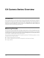
Geometry 1
The laser line is projected perpendicular to the object surface, while the camera views the object under
the triangulation angle α.
The height resolution can be approximated: ∆Z ≈ ∆X / sin(α)
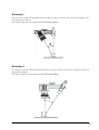
Geometry 2
The camera views the object perpendicularly to its surface, while the laser line is projected under the
triangulation angle α.
The height resolution can be approximated: ∆Z ≈ ∆X / tan(α)
α
C4-1280-GigE Camera Hardware Reference Manual Rev. 1.8
• 7
Geometry 3
The camera views the object under an angle α, while the laser line is projected under a different
angle β.
The height resolution can be approximated: ∆Z ≈ ∆X * cos(β) / sin(α + β),
in case α= β (direct reflex) : ∆Z ≈ ∆X / 2* sin(α)
α
β
Geometry 4
The camera views the object under an angle α, while the laser line is projected under a different
angle β at the camera side.
The height resolution can be approximated: ∆Z ≈ ∆X * cos(β) / sin(α - β),
β
α
8 •
C4-1280-GigE Camera Hardware Reference Manual Rev. 1.8
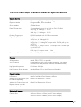
The C4-1280-GigE Camera General Specifications
Camera Controls
Synchonization Modes
Free running, Triggered, Software Triggered
Exposure Modes
Programmable, Pulse controlled
Shutter Modes
Global Shutter
Digital Trigger Input
2 optoisolated inputs, 5V or 24V with C4-I/O-Panel
VIL, logic ‚0’ Voltage
< 2.5V
VIH, logic ‚1’ Voltage > 3.5V
Encoder Trigger Input
RS422 Standard with 100 Ohm termination
Digital Output
2 optoisolated outputs
VOL, logic ‚0’ Voltage 0.5V
VOH, logic ‚1’ Voltage OC output with 4.7kOhm pull-up to
VCC I/O
Illumination Control
IOH, logic ‚1’ output current
up to VCC I/O
OC output with 4.7kOhm pull-
IOL, logic ‚0’ output current
8mA
Power 5V DC, 200mA, Modulation 20kHz
Features
3D-Algorithms
MAX, TRSH, COG, user specific
Smart Camera
Dedicated CPU for custom image processing, 1Gb image
memory, 256 Mb processor instruction and data memory
High Speed Acquisition
Full frame: 500 fps
High Dynamic Range Imaging
Multiple Slope Curve, Non-Destructive Readout
Optical Interface
Lens Mount
M42x1 with Back Focal Distance 6.52mm
Adapter for C-Mount lens (must
be ordered separately)
Back Focal Distance 17.52mm
Adapter for F-Mount lens with
Bajonett mount (must be
ordered separately)
Back Focal Distance 46.50 mm
Mechanical Interface
Camera Size
68 mm x 68 mm x 59 mm (with C-Mount adapter)
68 mm x 68 mm x 88 mm (with F-Mount adapter)
C4-1280-GigE Camera Hardware Reference Manual Rev. 1.8
• 9
Mechanical Interface
Mass (without optics)
340g (C-Mount), 410g (F-Mount)
Power connector
20-pin MDR
Ethernet connector
RJ45
Illunimation control connector
5-pin M9
Electrical Interface
Input Voltage
10 - 24V DC
Power consumption
<10W
Operating Temperature
0°C to +50°C (non condensing)
Output Data Interface
Gigabit Ethernet (IEEE 802.3)
Communication Protocol
GigE Vision with GeniCam
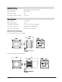
Mechanical Drawings
C4-1280-GigE with C-Mount adapter:
C4-1280-GigE with F-Mount adapter:
10 •
C4-1280-GigE Camera Hardware Reference Manual Rev. 1.8
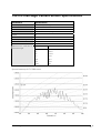
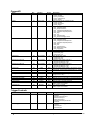
The C4-1280-GigE Camera Sensor Specifications
Parameters
Specifications
Sensitivity at peak response
20000 LSB / µJ / cm² @680nm
Resolution
1280 x 1024
Pixel Size
14µm x 14µm
Sensor Size
17.92mm x 14.34mm, diagonal: 22.95mm
Optics
1”
Sensor ADC Resolution
10 bit
Sensor Dynamic Range
90dB
Max. Internal Full-Frame Rate
500fps
Max. External Full-Frame Rate
80fps
Effective Frame / Profile Rate at
Max. Row Length
Number of Rows
Effective Frame / Profile Rate (Hz)
8
38462
16
23810
32
13699
64
7353
128
3817
256
1949
1024
495
Spectral sensitivity of C4-1280 sensor
C4-1280-GigE Camera Hardware Reference Manual Rev. 1.8
• 11
C4-1280-GigE Camera
Operational Reference
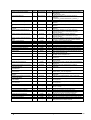
C4-1280-GigE Camera GenICam Features
DeviceInformation
Name
DeviceVendorName
DeviceModelName
DeviceManufacturerInfo
DeviceVersion
DeviceID
Rev.
1.0
1.0
1.0
1.0
1.0
Interface
IString
IString
IString
IString
IString
Access
R
R
R
R
R
DeviceFirmwareVersion
DeviceUserID
DeviceScanType
1.0
1.0
1.0
IString
IString
IEnumeration
R
R/W
R
DeviceReset
DeviceRegistersStreamingStart
1.0
1.2
ICommand
ICommand
W
W
DeviceRegistersStreamingEnd
1.2
ICommand
W
DeviceRegistersCheck
1.2
ICommand
W
DeviceRegistersValid
1.2
IBoolean
R
DeviceTemperature
DeviceMaxThroughput
AT
1.2
IFloat
IInteger
R
R
Description
The name of the device vendor.
The name of the device model.
Additional info from manufacturer about this device.
A string identifying the version of the device.
A unique identifier of the device, e.g., a serial number
or a GUID (User Data in GigE Boot register).
Version of firmware/software.
User-programmable device identifier.
Show the camera type:
- Areascan
Resets and reboots the device immediately.
Announces the start of registers streaming without
immediate checking for consistency.
Announces the end of registers streaming and
perform validation for registers consistency before
activating them. This will also update the
DeviceRegistersValid flag.
Performs an explicit register set validation for
consistency.
Indicates whether the current register set is valid and
consistent.
Device temperature in degrees Celsius (°C).
Maximum Bandwidth of data in Bytes/sec.
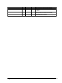
ImageFormatControls
Name
PayloadSize
Rev.
1.0
Interface
IInteger
Access
R
SensorWidth
SensorHeight
Width
1.0
1.0
1.0
IInteger
IInteger
IInteger
R
R
R/W
Height
1.0
IInteger
R/W
PixelFormat
1.0
IEnumeration
R/W
ReverseX
1.0
IBoolean
R/W
12 •
Description
PayloadSize provides the number of bytes transferred
for each image on the stream channel
Width of sensor (effective pixels)
Height of sensor (effective pixels)
Width of Image/Area Of Interest.
In Image-Mode writing this manipulates AOI[0].width.
Height of Image/Area Of Interest.
In Image-Mode writing this manipulates AOI[0].height
Format of the image pixels. For more details, see the
Pixel Format description chapter.
- Mono8
- Mono16
When set to true, this parameter flips the image
horizontally.
C4-1280-GigE Camera Hardware Reference Manual Rev. 1.8
Name
ReverseY
Rev.
1.0
Interface
IBoolean
Access
R/W
OffsetX
TestImageSelector
1.0
1.0
IInteger
IEnumeration
R/W
R/W
LinePitch
PixelDynamicRangeMin
PixelDynamicRangeMax
1.0
1.0
1.0
IInteger
IInteger
IInteger
R
R
R
Description
When set to true, this parameter flips the image
vertically.
X Offset of AOI
Selection of the test image to be used.
- Off
- GreySensorColumnPattern
Distance between consecutive lines in bytes.
Minimum pixel value sent by the camera.
Maximum pixel value sent by the camera.
AcquisitionControl
Name
AcquisitionStart
Rev.
1.0
Interface
ICommand
Access
W
AcquisitionStop
1.0
ICommand
W
AcquisitionMode
1.0
IEnumeration
R/W
AcquisitionAbort
1.0
ICommand
W
AcquisitionFrameCount
1.0
IInteger
R/W
AcquisitionFrameRateAbs
1.2
IFloat
R
AcquisitionStatusSelector
1.2
IEnumeration
R/W
AcquisitionStatus[AcquisitionStat
usSelector]
1.2
IBoolean
R
Description
Issues the START command. This starts the
acquisition.
Issues the STOP command. This stops the
acquisition.
Defines the type of acquisition:
- SingleFrame
- MultiFrame
- Continuous
Issues the ABORT command. This immediately
aborts the acquisition without completing the current
frame.
Number of frames to be acquired in MultiFrame
acquisition mode. The minimum allowable value is 1.
The frame rate of the imager. Absolute units are in
Hz.
Selector for AcquisitionStatus to read:
- AcquisitionTriggerWait
- AcquisitionActive
- AcquisitionTransfer
- FrameTriggerWait
Status of the selected acquisition flag
CameraControls – AOIs (Areas Of Interest)
Name
MaxNumAOIs
NumAOIs
ImageModeAoiSelector
AoiSelector
AoiHeight
AoiOffsetY
AoiThreshold
Rev.
AT
AT
AT
AT
AT
AT
Interface
IInteger
IInteger
IInteger
IInteger
IInteger
IInteger
AT
IInteger
Access
R
R/W
R/W
R/W
R/W
R/W
R/W
Description
Maximum number of AOIs.
Number of used AOIs.
Selects the AOI to show in image mode
Selects which AOI to control
Number of sensor rows in AOI
Offset distance in rows between the first row of AOI
and the first row of sensor chip
Intensity threshold value for selected AOI.
CameraControls – ModeAndAlgorithmControls
Name
CameraMode
Rev.
AT
Interface
IEnumeration
Access
R/W
ProfilesPerFrame
AT
IInteger
R/W
AbsOffsetPos
AT
IBoolean
R/W
TrshFirstFalling
AT
IBoolean
R/W
NumCOGSP
PosValidationEn
AT
AT
IInteger
IBoolean
R/W
R/W
C4-1280-GigE Camera Hardware Reference Manual Rev. 1.8
Description
Selects the camera mode or algorithm:
- Image
- CenterOfGravity
- Threshold
- MaximumIntensity
This feature represents the number of Profiles per
Frame in 3D-Mode expelled by the camera.
True: Position values are referenced to the first row
of sensor chip (absolute position).
False: Position values are referenced to the first row
of AOI.
Stops the position calculation along an AOI column,
as soon as the falling edge of a Gauss curve is
detected.
Number of subpixel bits of COG output (0-6).
Enable validation of position value of a Gauss curve
using tolerances for width and sum of intensity.
Perform validation during scan of image column and
• 13
Name
Rev.
Interface
Access
ClearInvalidPos
AT
IBoolean
R/W
ValidationWidthMin
AT
IInteger
R/W
ValidationWidthMax
AT
IInteger
R/W
ValidationSumMin
AT
IInteger
R/W
ValidationSumMax
AT
IInteger
R/W
Description
immediately after detecting a Gauss falling edge.
Clear the result, if the position value is invalid.
Enable validation of position value using tolerances
for width and sum of intensity. Perform validation at
the end of scan of image column. Invalid position
values are set to zero in all DCs.
Minimum width of valid intensity distribution in 3Dmode.
Maximum width of valid intensity distribution in 3Dmode.
Minimum sum of intensity of valid intensity
distribution in 3D-mode.
Maximum sum of intensity of valid intensity
distribution in 3D-mode.
CameraControls – ModeAndAlgorithmControls - AoiTracking
Name
AoiTrackingEnable
Rev.
AT
Interface
IBoolean
Access
R/W
AoiTrackingMinNumPixel
AT
IInteger
R/W
AoiTracking_P
AoiTracking_I
AoiTracking_D
AoiTrackingUpdateRate
AoiTrackingSensorWriteTimeout
AT
AT
AT
AT
AT
IFloat
IFloat
IFloat
IInteger
IInteger
R/W
R/W
R/W
R/W
R/W
Description
True: AOI-Tracking mode is enabled
False: AOI-Tracking mode is disabled
Minimum number of required pixel (one pixel per
column) to start AOI tracking algorithm
Proportional gain of PID controller
Integral gain of PID controller
Derivative gain of PID controller
Update frequency of tracking algorithm (Hz)
AOI tracking senosr write timeout in microseconds
(µs)
CameraControls – ModeAndAlgorithmControls - AoiSearch
Name
AoiSearchEnable
Rev.
AT
Interface
IBoolean
Access
R/W
AoiSearchHeight
AoiSearchOffsetY
AT
AT
IInteger
IInteger
R/W
R/W
Description
True: AOI-Search mode is activated
False: AOI-Search mode is disabled
Height of search AOI
Vertical offset from the origin to the search AOI
CameraControls – ModeAndAlgorithmControls - ColumnEvaluationMask
Name
ColRangeStart
ColRangeEnd
ColRangeEnableCommand
ColRangeDisableCommand
ColRangeActivate
Rev.
AT
AT
AT
AT
AT
Interface
IInteger
IInteger
ICommand
ICommand
ICommand
Access
R/W
R/W
W
W
W
Description
Column start index
Column end index
Enable all columns from RangeStart to RangeEnd
Disable all columns from RangeStart to RangeEnd
Activate complete ColumnEvaluationMask and write
data into flash memory
CameraControls – SensorControls
Name
SensorFrameCounter
SensorReadoutTime
ExposureTimeAbs
FramePeriode
FrameRate
ExposureMode
Rev.
AT
AT
AT
AT
AT
AT
Interface
IInteger
IInteger
IInteger
IInteger
IFloat
IEnumeration
Access
R
R
R/W
R/W
R
R
MultipleSlopeMode
AT
IEnumeration
R/W
DualSlopeTime
TripleSlopeTime
NumberOfNDRFrames
AT
AT
AT
IInteger
IInteger
IInteger
R/W
R/W
R/W
14 •
Description
Sensor frame counter.
Sensor Readout Time in µs.
Sensor integration time in µs.
Time between two frames in µs.
Frame rate in Hz
Sensor exposure mode:
- Interleaved (the sensor integration and readout
are performed in parallel).
MultipleSlope Mode:
- SingleSlope
- DualSlope
- TripleSlope
DualSlopeTime in % of sensor integration time
TripleSlopeTime in % of sensor integration time
Number of NDR frames
C4-1280-GigE Camera Hardware Reference Manual Rev. 1.8
NDRMode
AT
IEnumeration
R/W
NDRSingleFrameNumber
NDRExposureTimeAbs_1
NDRExposureTimeAbs_2
NDRExposureTimeAbs_3
NDRExposureTimeAbs_4
AT
AT
AT
AT
AT
IInteger
IInteger
IInteger
IInteger
IInteger
R/W
R/W
R/W
R/W
R/W
Non Destructive Readout (NDR) Mode:
- Off
- On
- SingleFrameMode.
NDR single frame number.
NDR exposure time 1.
NDR exposure time 2.
NDR exposure time 3.
NDR exposure time 4.
CameraControls – SensorControls – AdvancedSensorsettings
Name
FPNCorrection
Rev.
AT
Interface
IEnumeration
Access
R/W
GainAbs
1.2
IEnumeration
R/W
AntiBlooming
ResetTS
Reset
ResetDS
Precharge
MemH
MemL
BlackLevelAdjust
Enable automatic SERDES
recalibration
AT
AT
AT
AT
AT
AT
AT
AT
AT
IFloat
IFloat
IFloat
IFloat
IFloat
IFloat
IFloat
IInteger
IBoolean
R/W
R/W
R/W
R/W
R/W
R/W
R/W
R/W
R/W
Description
FPN Correction:
- Enable
- Disable
Gain value:
-1
- 1.5
-2
- 2.25
-3
-4
Antiblooming Voltage (DAC 1)
Reset Voltage Triple Slope (DAC 2)
Reset Voltage (DAC 3)
Reset Dual Slope (DAC 4)
Precharge Voltage (DAC5)
Pixels memory element high level (DAC6)
Pixels memory element low level (DAC7)
Adjustment of black level.
Enable automatic SERDES recalibration on data
channel error.
CameraControls – DataOutput
Name
EnableDC0
EnableDC1
EnableDC2
EnableDC0Shift
Rev.
AT
AT
AT
AT
Interface
IBoolean
IBoolean
IBoolean
IBoolean
Access
R/W
R/W
R/W
R/W
EnableDC2TrshSP
AT
IBoolean
R/W
EnableDC1TrshWidth
AT
IBoolean
R/W
EnableDC1Width
AT
IBoolean
R/W
EnableDC1Flags
AT
IBoolean
R/W
Description
Activates the output data channel DC0.
Activates the output data channel DC1.
Activates the output data channel DC2.
Right shift twice the intensity value in DC0, when
PixelFormat is Mono8.
Controls the output in channel DC2, when TRSH
algorithm is selected:
True: DC2 outputs the position value with 1
subpixel.
False: DC2 outputs the right edge position.
Controls the output in channel DC1, when TRSH
algorithm is selected:
True: DC1 outputs the laser line width.
False: DC1 outputs the left edge position.
Controls the output in channel DC1, when COG
algorithm is selected:
True: DC1 outputs the laser line width.
False: DC1 outputs the left edge position.
When in 16 bit mode, the bits 12-15 of output
channel DC1 contain additional algorithm flags
CameraControls – Commands
Name
StartPulse
StopPulse
TriggerPulse
CalibSensor
RstFrameCnt
SearchAoi
Rev.
AT
AT
AT
AT
AT
AT
Interface
ICommand
ICommand
ICommand
ICommand
ICommand
ICommand
Access
W
W
W
W
W
W
C4-1280-GigE Camera Hardware Reference Manual Rev. 1.8
Description
Send Start pulse.
Send Stop pulse.
Send Trigger pulse.
Start internal sensor FPN calibration.
Reset frame counter to zero.
Fit AOI to laser line position. Supports only one
AOI
• 15
CameraIO
Name
Input1
Rev.
AT
Interface
IEnumeration
Access
R
Input2
AT
IEnumeration
R
Output1
AT
IEnumeration
RW
Output2
AT
IEnumeration
RW
TriggerOverrun
Input1Level
AT
AT
IBoolean
IEnumeration
R
R
Input2Level
AT
IEnumeration
R
RS422ChannelALevel
AT
IEnumeration
R
RS422ChannelBLevel
AT
IEnumeration
R
LaserPower
AT
IFloat
R/W
TurnLaserOn
TurnLaserOnAuto
VoltageIn
AT
AT
AT
IBoolean
IBoolean
IFloat
R/W
R/W
R
Output1MinPulseWidth
Output2MinPulseWidth
Output1Delay
Output2Delay
Output1Invert
AT
AT
AT
AT
AT
IInteger
IInteger
IInteger
IInteger
IBoolean
R/W
R/W
R/W
R/W
R/W
Output2Invert
AT
IBoolean
R/W
Rev.
AT
Interface
IEnumeration
Access
R/W
AT
IEnumeration
R/W
Description
Lists the input signals available for IN1:
- Input1_Unused.
- Input1_FrameStart
- Input1_EnableFrame
- Input1_Trigger
Lists the input signals available for IN2:
- Input2_Unused.
- Input2_StopFrame
- Input2_Trigger
Selects the output signal for OUT1:
- Out1_IntegrationActive
- Out1_SequencerActive
- Out1_IntegrationDualSlopeActive
- Out1_IntegrationTripleSlopeActive
- Out1_High
- Out1_Low
- Out1_InternalTrigger
- Out1_SequencerTriggerActive
Selects the output signal for OUT2:
- Out2_IntegrationActive,
- Out2_IntegrationDualSlopeActive
- Out2_IntegrationTripleSlopeActive
- Out2_High
- Out2_Low
- Out2_TriggerOverrun
- Out2_ResolverCountDir
- Out2_TriggerBusy
Trigger Overrun Flag.
The voltage level of IN1:
- Input1Level_High
- Input1Level_Low
The voltage level of IN2:
- Input2Level_High
- Input2Level_Low
Voltage level of RS422 Channel A:
- RS422ChannelALevel_High
- RS422ChannelALevel_Low
Volatge level of RS422 Channel B
- RS422ChannelBLevel_High
- RS422ChannelBLevel_Low
Sets the output analog voltage of illumination control
in the range 0.0-5.0 V DC (corresponds to 0...100%)
Laser turn on/off.
Laser turn on automatically during sensor integration.
Reads the input analog voltage of illumination control
(range 0.0-5.0 V DC)
Output1 minimum pulse width in microseconds (µs)
Output2 minimum pulse width in microseconds (µs)
Output1 delay in microseconds (µs)
Output2 delay in microseconds (µs)
True: Output1 inverted
False: Output1 not inverted
True: Output1 inverted
False: Output1 not inverted
TriggerControls
Name
SequencerMode
ProfileTriggerMode
16 •
Description
Selects the start trigger mode:
- FreeRun
- StartStopCameraInput12
- StartCameraInput1
- GateCameraInput1
- StartStopCameraInput12Event
- AutoStart
Selects the profile trigger mode:
- FreeRun
- CameraInput1
- CameraInput2
C4-1280-GigE Camera Hardware Reference Manual Rev. 1.8
Name
ClearTriggerOverrun
Rev.
AT
Interface
ICommand
Access
W
Description
- EncoderResolverInterfaceRS422.
Command to clear the trigger overrun flag.
TriggerControls – ResolverRS422
Name
TriggerDivider
TriggerCoord
TriggerDirectionMode
Rev.
AT
AT
AT
Interface
IInteger
IInteger
IBoolean
Access
R/W
R
R/W
TriggerReverseDirection
TriggerDividerLoadAtStart
AT
AT
IBoolean
IBoolean
R/W
R/W
TriggerSingleChannelMode
LoadTriggerDivider
AT
AT
IBoolean
ICommand
R/W
W
ClearTriggerCoord
TriggerCoordinateCountAlways
AT
AT
ICommand
IBoolean
W
R/W
UseAlternateResolverInputs
AT
IBoolean
R/W
UseAlternateResolverInputsInv
erted
AT
IBoolean
R/W
Description
Trigger divider.
Resolver trigger coordinates
A sensor image is triggered when the internal pulse
counter is countdown to 0. Upon start of acquisition,
the initial value of pulse counter is equal to trigger
divider.
This parameter controls the behaviour of the pulse
counter:
True: The pulse counter is decreased and
countdown to 0, when resolver pulses are
generated from both moving directions (forwards
and backwards).
False: The pulse counter is decreased and
countdown to 0, when resolver pulses are
generated from one moving direction only (e.g.
forwards). In that case, pulses corresponding to the
opposite moving direction (e.g. backwards) will
increase the pulse counter.
Reverse the pulse count direction.
Loads the value of trigger divider into the pulse
counter, when start trigger occurs.
Enables trigger mode using single channel resolver.
Command to load the value of trigger divider into
the pulse counter.
Reset trigger coordinate counter
Controls when trigger coordinates shall be counted:
True: Trigger coordinates are counted always
False: Trigger coordinates are counted only during
image acquisition
True: Use IN1/IN2 instead of A/B as encoder input
False: Use A/B as encoder input
True: Invert encoder input over IN1/IN2
False: Do not invert encoder input over IN1/IN2
TriggerControls – AutoStart
Name
AutoStartThreshold
Rev.
AT
Interface
IInteger
Access
R/W
AutoStartNumPixel
AT
IInteger
R/W
AutoStartOption
AT
IEnumeration
R/W
AutoStartBufferOption
AT
IEnumeration
R/W
Description
Defines the position within AOI to trigger the
AutoStart. Valid values are:
When AbsolutePosition = FALSE : 0 - AOI-Height
When AbsolutePosition = TRUE : 0 - Sensor-Height
Minimum number of valid laser positions within AOI
required to trigger the Autostart
PosLessThanAutostartThreshold: Start when laser
position is less-than AutoStartThreshold
PosGreaterThanAutostartThreshold: Start when
laser position is greater-than AutoStartThreshold
Defines whether the history buffer should be
transmitted as first frame or not
-none
-HistoryBuffer
GigEVisionTransportLayer
Name
GevVersionMajor
Rev.
1.2
Interface
IInteger
Access
R
GevVersionMinor
1.2
IInteger
R
GevDeviceModeIsBigEndian
1.2
IBoolean
R
C4-1280-GigE Camera Hardware Reference Manual Rev. 1.8
Description
This field represents the major version of the GigE
Vision specification supported by this device
This field represents the minor version of the GigE
Vision specification supported by this device
This represents the endianess of bootstrap registers
(FALSE: Little-endian device TRUE: Big-endian
device)
• 17
Name
GevDeviceModeCharacterSet
Rev.
1.2
Interface
IEnumeration
Access
R
GevInterfaceSelector
1.2
IEnumeration
R
GevMACAddress
GevSupportedIPConfigurationLLA
1.2
1.2
IInteger
IBoolean
R
R/W
GevSupportedIPConfigurationDHC
P
GevSupportedIPConfigurationPers
istentIP
GevCurrentIPConfigurationLLA
1.2
IBoolean
R/W
1.2
IBoolean
R/W
1.2
IBoolean
R
GevCurrentIPConfigurationDHCP
1.2
IBoolean
R
GevCurrentIPConfigurationPersist
entIP
GevCurrentIPAddress
GevCurrentSubnetMask
GevCurrentDefaultGateway
GevPersistentIPAddress
GevPersistentSubnetMask
GevPersistentDefaultGateway
GevLinkSpeed
GevFirstURL
1.2
IBoolean
R
1.2
1.2
1.2
1.2
1.2
1.2
1.2
1.2
IInteger
IInteger
IInteger
IInteger
IInteger
IInteger
IInteger
IString
R
R
R
R/W
R/W
R/W
R
R
GevSecondURL
1.2
IString
R
GevNumberOfInterfaces
1.2
IInteger
R
GevMessageChannelCount
1.2
IInteger
R
GevStreamChannelCount
1.2
IInteger
R
GevSupportedOptionalCommands
UserDefinedName
GevSupportedOptionalCommands
SerialNumber
GevSupportedOptionalCommands
EVENTDATA
GevSupportedOptionalCommands
EVENT
GevSupportedOptionalCommands
PACKETRESEND
GevSupportedOptionalCommands
WRITEMEM
GevSupportedOptionalCommands
Concatenation
GevHeartbeatTimeout
GevTimestampTickFrequency
1.2
IBoolean
R
1.2
IBoolean
R
1.2
IBoolean
R
1.2
IBoolean
R
1.2
IBoolean
R
1.2
IBoolean
R
1.2
IBoolean
R
1.2
1.2
IInteger
IInteger
R/W
R
GevTimestampControlLatch
GevTimestampControlReset
GevTimestampValue
1.2
1.2
1.2
ICommand
ICommand
IInteger
R
R
R
GevStreamChannelSelector
GevSCPInterfaceIndex
GevSCPSPacketSize
GevSCPD
1.2
1.2
1.2
1.2
IInteger
IInteger
IInteger
IInteger
R/W
R
R/W
R/W
18 •
Description
This feature represents the character set of all boot
strap strings:
- CharacterSet_UTF8
Indicates the index of the network interface to
configure:
- EnumEntry_GevInterfaceSelector_Interface_0
48-bit MAC address of the selected interface
Indicate if LLA (Auto-IP) is supported by the selected
interface
Indicate if DHCP is supported by the selected
interface
Indicate if Persistent IP is supported by the selected
interface
This feature indicates if Link Local Address IP
configuration scheme is activated on the given
network interface
This feature indicates if DHCP Address IP
configuration scheme is activated on the given
network interface
This feature indicates if PersistentIP IP configuration
scheme is activated on the given network interface
IP address of the selected interface
Subnet mask of the selected interface
Default gateway of the selected interface
Persistent IP address for the selected interface
Persistent subnet mask for the selected interface
Persistent default gateway for the selected interface
Link speed in Mbps.
NULL-terminated string providing the first URL to the
XML device description file
NULL-terminated string providing the second URL to
the XML device description file
Indicates the number of physical network interfaces on
this device
Indicates the number of message channels supported
by this device
Indicates the number of stream channels supported by
this device
Indicates if the User-defined Name register is
supported
Indicates if the Serial Number register is supported
Indicates if EVENTDATA_CMD and
EVENTDATA_ACK are supported
Indicates if EVENT_CMD and EVENT_ACK are
supported
Indicates if PACKETRESEND_CMD is supported
Indicates if WRITEMEM_CMD and WRITEMEM_ACK
are supported
Indicates if multiple operations in a single message
are supported
Current heartbeat timeout in milliseconds
64-bit value indicating the number of timestamp clock
tick in 1 second
Latches the current timestamp value of the device
Resets the timestamp count of the device
Latched 64-bit value of the timestamp. Value must first
be latched using GevTimestampControlLatch.
Indicate which stream channel to configure
Index of network interface
The size of the stream packet to send on this channel
Delay (in timestamp counter unit) to insert between
each packet for this stream channel
C4-1280-GigE Camera Hardware Reference Manual Rev. 1.8
UserSets
Name
UserSetSelector
Rev.
1.2
Interface
IEnumeration
Access
R/W
Description
Selects the feature User Set to load, save or
configure:
- Factory
- UserSet1
- UserSet2
- UserSet3
Loads the User Set specified by UserSetSelector to
the device and makes it active.
Saves the selected User Set specified by
UserSetSelector to persistent memory.
Selects the feature User set to load at power up:
- Factory
- UserSet1
- UserSet2
- UserSet3
UserSetLoad[UserSetSelector]
1.2
ICommand
W
UserSetSave[UserSetSelector]
1.2
ICommand
W
UserSetDefaultSelector
1.2
IEnumeration
R/W
Rev.
1.2
1.2
Interface
IBoolean
IEnumeration
Access
R/W
R/W
Description
Enables the chunk data mode.
Selects the chunk data mode:
- OneChunkPerFrame
- OneChunkPerProfile
Rev.
1.2
Interface
IEnumeration
Access
R/W
1.2
IEnumeration
R/W
Description
Selector for the Event to control:
- None
- AcquisitionStart
- AcquisitionEnd
- TransferStart
- TransferEnd
- AoiTrackingOn
- AoiTrackingOff
-AoiSearchFailed
Notification type to issue when selected event
occurs:
- Off
- GigEVisionEvent
Rev.
1.2
Interface
IEnumeration
Access
R/W
FileOperationSelector
1.2
IEnumeration
R/W
FileOperationExecute
1.2
ICommand
W
FileOpenMode
1.2
IEnumeration
R/W
FileAccessOffset
1.2
IInteger
R/W
FileAccessLength
1.2
IInteger
R/W
ChunkDataControl
Name
ChunkModeActive
ChunkModeSelector
EventGeneration
Name
EventSelector
EventNotification
FileAccessControl
Name
FileSelector
C4-1280-GigE Camera Hardware Reference Manual Rev. 1.8
Description
Selects the target file in the device.:
- UserSetDefault
- UserSet1
- UserSet2
- UserSet3
- UserData
- ColStatisticBits
Selects the target operation for the selected file in the
device. This Operation is executed when the
FileOperationExecute feature is called:
- Open
- Close
- Read
- Write
Executes the operation selected by
FileOperationSelector on the selected file.
Selects the access mode in which a file is opened in
the device.
- Read
- Write
- ReadWrite
Controls the Offset of the mapping between the
device file storage and the FileAccessBuffer.
Controls the Length of the mapping between the
• 19
Name
Rev.
Interface
Access
FileOperationStatus
1.2
IEnumeration
R
FileOperationResult
1.2
IInteger
R
FileSize
1.2
IInteger
R
20 •
Description
device file storage and the FileAccessBuffer.
Represents the file operation execution status:
- Success
- Failure
Represents the file operation result. For Read or
Write operations, the number of successfully
read/written bytes is returned.
Represents the size of the selected file in bytes.
C4-1280-GigE Camera Hardware Reference Manual Rev. 1.8
The GenICam Features Configuration of C4-1280-GigE
Due to dependencies of the XML nodes of C4-1280-GigE registers, it is recommended to follow a
specific order, when configuring the GenICam features of the camera. The list shown below,
generated as a CXC file by the CX-Explorer, demonstrates an example of the correct write order:
CameraMode CenterOfGravity
ProfileTriggerMode
FreeRun
EnableDC2
1
EnableDC1
0
OffsetX 0
TestImageSelector
Off
PixelFormat
Mono16
ReverseY
0
ReverseX
0
Width 1280
CameraMode CenterOfGravity
ProfilesPerFrame 100
ClearInvalidPos 0
PosValidationEn 0
AbsOffsetPos
0
TrshFirstFalling 0
NumCOGSP
6
ValidationWidthMin
0
ValidationWidthMax
1023
ValidationSumMin
0
ValidationSumMax
65535
AoiTrackingEnable
0
AoiTracking_P 0.65
AoiTracking_I
0.5
AoiTracking_D 0.12
AoiTrackingUpdateRate 100
AoiTrackingSensorWriteTimeout 10000
AoiTrackingMinNumPixel 100
AoiSearchEnable 0
AoiSearchHeight 1024
AoiSearchOffsetY
0
ColRangeStart 0
ColRangeEnd 1279
NumAois
1
AoiSelector
1
AoiHeight
1024
AoiOffsetY
0
AoiThreshold
250
ExposureTimeAbs
100
FramePeriode 2007
MultipleSlopeMode
SingleSlope
NDRMode
Off
FPNCorrection Enable
GainAbs
Gain1
AntiBlooming
0
ResetTS 1.8
Reset 3.5
ResetDS 2.5
Precharge
0.7
C4-1280-GigE Camera Hardware Reference Manual Rev. 1.8
• 21
MemH 3.2
MemL 2.55
BlackLevelAdjust 80
EnableDC0
0
EnableDC1
0
EnableDC1TrshWidth
0
EnableDC1Width
0
EnableDC1Flags 0
EnableDC2
1
EnableDC2TrshSP
0
EnableDC0Shift 0
AcquisitionFrameCount 1
AcquisitionMode Continuous
Output1 Out1_SequencerActive
Output2 Out2_IntegrationActive
LaserPower
0
TurnLaserOn
0
TurnLaserOnAuto
0
Output1MinPulseWidth 0
22 •
C4-1280-GigE Camera Hardware Reference Manual Rev. 1.8
The C4-1280-GigE Camera Algorithms
The C4-1280-GigE camera can be operated both in a variety of 3D profile modes and in image
mode. The current operation mode can be chosen by setting the parameter Camera Controls→
ModeAndAlgorithmControls→CameraMode.
The frame rate can be increased in all camera modes by reducing the AOI size. In the image mode
the frame rate is limited by the output rate of the camera interface (GigE). However, due to reduced
data size in profile mode the frame rate is limited only by the sensor output rate. As a matter of
principle the processing speed is independent of the chosen profile mode and is determined by the
AOI size.
In all profile modes only intensity values higher than the AOI intensity threshold AOI_TRSH are
processed in order to suppress weak signal noise. In case that no position value can be found, e.g. no
intensity value is higher than threshold, the position value 0 is returned.
The Image Mode (IMG)
In the image mode the C4-1280-GigE camera is operated similar to a standard CMOS camera. In
this mode grey scale data of 8 or 10 bit resolution are acquired over the camera interface.
Furthermore, the sensor can be divided into multiple regions, whose data can be summarised in one
output frame.
C4-1280-GigE Camera Hardware Reference Manual Rev. 1.8
• 23
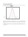
The Maximum Intensity Profile Mode (MAX)
In this mode the position of the maximum intensity of laser beam profile is calculated. The result
includes the position value of the maximum (PMAX) as well as the maximum intensity value (IMAX).
IMAX
AOI_TRSH
PMAX
PR
The calculation of position value is performed with simple pixel accuracy, i.e. the evaluation of 1024
rows delivers a position range from 0 to 1023 pixels (10 bit). If there is more than one local
maximum, the position of the first detected maximum is output.
24 •
C4-1280-GigE Camera Hardware Reference Manual Rev. 1.8
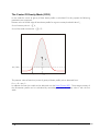
The Threshold Mode (TRSH)
In this mode the position of left (PL) and right (PR) edge of the laser beam profile are detected for a
given threshold value of intensity AOI_TRSH.
AOI_TRSH
PL
PTRSH
PR
The position value of the laser line is approximated: PTRSH = (PL+PR) / 2. In order to simplify the digital
representation the division over 2 is not performed and thus an integer representation with one
subpixel is realised. The evaluation of 1024 rows delivers a position range from 0 to 2047 pixels
(11 bit).
In threshold mode the camera can output either the left and right threshold position separately or the
subpixel position (PL+PR) and the line width (PR-PL). Moreover, the maximum intensity value can be
optionally output.
C4-1280-GigE Camera Hardware Reference Manual Rev. 1.8
• 25
The Center Of Gravity Mode (COG)
In this mode the center of gravity of laser beam profile is calculated. For this purpose the following
parameters are computed:
Position value of the left edge of laser beam profile for a given intensity threshold value PL ,
Sum of intensity value Is = ∑ Ip,
Sum of first order moment Ms = ∑Ip * P .
IS
AOI_TRSH
PL
PCOG
The position value of laser line (center of gravity of beam profile) is then obtained from:
PCOG = PL + Ms / Is .
In addition the laser line width can be delivered over the Data Channel DC1. The average intensity of
the illumination profile can be calculated by normalising the sum of intensity value Is with the line
width.
26 •
C4-1280-GigE Camera Hardware Reference Manual Rev. 1.8
The High Dynamic Range 3D Feature (HDR-3D) of C41280-GigE
One of the most powerful features of C4-1280-GigE is the HDR-3D (High Dynamic Range)
functionality, which allows to scan materials and surfaces with inhomogeneous reflection properties.
Using HDR-3D the dynamic range of image intensity is extended up to 90dB, thus avoiding intensity
saturation.
The HDR-3D comprises two independent sensor functions:
MultipleSlope Function
The aim of the MultipleSlope function is to avoid the saturation of pixels during sensor chip exposure.
In order to perform this task, threshold values for the recorded light amount and produced voltage are
defined. If within a predefined time the threshold is exceeded then the voltage of the pixel is reset to
the threshold value and the integration continues until the exposure is completed. This mode is known
as DualSlope. There is also an option of resetting the pixel voltage twice, which is called TripleSlope
mode. The reset time of DualSlope and TripleSlope mode is configured as percentage of the
integration time. The reset voltage levels are factory preset to a specific optimized value obtained from
extensive tests and should not be modified. Advanced users can modify the reset levels by changing
the XML grid visibility to “Guru”.
C4-1280-GigE Camera Hardware Reference Manual Rev. 1.8
• 27
SingleSlope-Modus (default mode)
Intensity
1
1
Saturation
2
2
3
3
Integration
time
DualSlope mode
Intensity
1
1
Saturation
2
2
3
3
DS Reset
Level
DS Reset
Time
Integration
time
TripleSlope mode
Intensity
1
Saturation
2
3
1
2
TS Reset
Level
DS Reset
Level
3
DS Reset TS Reset
Time
Time
Integration
time
28 •
C4-1280-GigE Camera Hardware Reference Manual Rev. 1.8
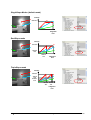
Application of MultipleSlope function in the image of a laser line projected on a surface with nonhomogeneous reflectivity (black & white pattern)
DualSlope
TripleSlope
1100
1100
1000
1000
1000
900
900
900
800
800
800
700
600
500
400
300
200
100
Intensity
1100
Intensity
Intensity
SingleSlope
700
600
500
400
300
200
0
5
10
15
20
25
30
35
Sensor row #
40
700
600
500
400
300
200
100
100
0
5
10
15
20
25
30
Sensor row #
C4-1280-GigE Camera Hardware Reference Manual Rev. 1.8
35
40
0
5
10
15
20
25
30
35
40
Sensor row #
• 29
Non-Destructive Readout (NDR) Mode
With the NDR mode it is possible to readout of up to 4 images at
different integration levels during one exposure period. The
principle is comparable to multiple scans with different integration
times with the advantage of taking all data during one single
integration period. It allows the combination of profile data from
different integration levels and it ensures accurate profile data
even for difficult surfaces with strong changes in reflectance.
The following timing diagram shows the function of NDR with 2 frames, when subsequent sensor
images are acquired. The exposure times for NDR frame 1 and 2 are depicted with It1 and It2
respectively. Please note that the readout of the second frame R2 can not begin unless the first frame
R1 has been readout. The same applies also between two subsequent sensor images, i.e. the first NDR
frame of sensor image 2 can not be readout unless the last NDR frame of sensor image 1 has been
readout.
Trigger Sensor
Image 1
Trigger Sensor
Image 2
I(2)
I(1)
It1
It1
R1(2)
R1(1)
It2
It2
R2(2)
R2(1)
Readout NDR
Frame 1 of
Sensor Image 1
30 •
Readout NDR
Frame 2 of
Sensor Image 1
Readout NDR
Frame 1 of
Sensor Image 2
Readout NDR
Frame 2 of
Sensor Image 2
C4-1280-GigE Camera Hardware Reference Manual Rev. 1.8
The Data Output Format of C4-1280-GigE
The image and 3D data output is performed by selecting the data channel DC0-DC2 (node Camera
Controls→DataOutput). Depending on the algorithm the data can be acquired by enabling the
corresponding output Data Channel (DC). Every DC is saved in a new image row. The bit depth of
output data depends on the selected algorithm. In 3D mode the camera outputs data with 16 bit. In
Image mode the camera can output 8 or 16 bit data. When in 8 bit Image mode, the DC0 delivers
the 8 most significant bits of the 10 bit intensity data.
The Data Channel Assignment DC0-DC2
Alg.
DC0
DC1
DC2
IMG
Grey scale values
Not used
Not used
TRSH
Maximum intensity
Left edge of laser line
(PosL) or line width
(PosR-PosL)
Right edge of laser line (PosR) or
line position with 1/2 pixel
accuracy (PosL+PosR)
MAX
Maximum intensity
Left edge of laser line
(PosL)
Position of maximum intensity
(PosM)
COG
Sum of intensity values Is
Left edge of laser line
(PosL) or laser line width
(PosR-PosL)
Line position with 1/X pixel
resolution, where
X=1,2,4,8,16,32,64
Alg. Flags – Output over DC1 (16 bit mode):
Bit14 = LEFT_TRSH_FOUND_FLAG: indicates that the left edge of laser line was found
Bit15 = RIGHT_TRSH_FOUND_FLAG: indicates that the right edge of laser line was found
C4-1280-GigE Camera Hardware Reference Manual Rev. 1.8
• 31
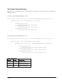
The Output Frame Structure
Depending on configuration, the C4-1280-GigE writes data to the output frame according to
following scheme:
1) NDR mode disabled (NDRMode=”Off”)
for (profile_idx=1; profile_idx <=ProfilesPerFrame; profile_idx ++)
{
for(AOI_idx=1; AOI_idx<=NumAOIs; AOI_idx++)
{
if(EnableDC0==true)
write_data_of_DC0 (AOI_idx);
if(EnableDC1==true)
write_data_of_DC1 (AOI_idx);
if(EnableDC2==true)
write_data_of_DC2 (AOI_idx);
}
}
2) NDR mode enabled (NDRMode=”On”)
for (profile_idx=1; profile_idx <=ProfilesPerFrame/2; profile_idx ++)
{
for(AOI_idx=1; AOI_idx<=NumAOIs; AOI_idx++)
{
for(NDR_idx=1: NDR_idx <= NumberOfNDRFrames; NDR_idx ++)
{
if(EnableDC0==true)
write_data_of_DC0 (AOI_idx,NDR_idx);
if(EnableDC1==true)
write_data_of_DC1 (AOI_idx,NDR_idx);
if(EnableDC2==true)
write_data_of_DC2 (AOI_idx,NDR_idx);
}
}
}
Index Definition
Index #
Range
Description
Profile_idx 1-16384
Index of Profile
AOI_idx
1-4
Index of sensor AOI
NDR_idx
1-4
Index of NDR frame
32 •
C4-1280-GigE Camera Hardware Reference Manual Rev. 1.8
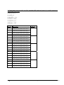
Examples of Output Frame Structure
1) Configuration with single AOI, single DC, disabled NDR mode and output of 6 profiles resulting to
a frame height of 6 rows:
ProfilesPerFrame=10
NumAOIs=1
EmableDC0= false,
EnableDC1=false
EnableDC2=true
NDRMode=”Off”
Row #
Description
Profile #
1
Data of DC2 readout from AOI1
1
2
Data of DC2 readout from AOI1
2
3
Data of DC2 readout from AOI1
3
4
Data of DC2 readout from AOI1
4
5
Data of DC2 readout from AOI1
5
6
Data of DC2 readout from AOI1
6
C4-1280-GigE Camera Hardware Reference Manual Rev. 1.8
• 33
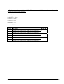
2) Configuration with two AOIs, two DCs, disabled NDR mode and output of 5 profiles resulting to
frame height of 20 rows:
ProfilesPerFrame=5
NumAOIs=2
EmableDC0= true,
EnableDC1=false
EnableDC2=true
NDRMode=”Off”
Row #
Description
Profile #
1
Data of DC0 readout from AOI1
1
2
Data of DC2 readout from AOI1
3
Data of DC0 readout from AOI2
4
Data of DC2 readout from AOI2
5
Data of DC0 readout from AOI1
6
Data of DC2 readout from AOI1
7
Data of DC0 readout from AOI2
8
Data of DC2 readout from AOI2
9
Data of DC0 readout from AOI1
10
Data of DC2 readout from AOI1
11
Data of DC0 readout from AOI2
12
Data of DC2 readout from AOI2
13
Data of DC0 readout from AOI1
14
Data of DC2 readout from AOI1
15
Data of DC0 readout from AOI2
16
Data of DC2 readout from AOI2
17
Data of DC0 readout from AOI1
18
Data of DC2 readout from AOI1
19
Data of DC0 readout from AOI2
20
Data of DC2 readout from AOI2
34 •
2
3
4
5
C4-1280-GigE Camera Hardware Reference Manual Rev. 1.8
3) Configuration with single AOI, single DC, NDR mode with two NDR frames and output of 3 profiles
resulting to a frame height of 6 rows:
ProfilesPerFrame=6
NumAOIs=1
EmableDC0= false,
EnableDC1=false
EnableDC2=true
NDRMode=”On”
NumberOfNDRFrames=2
Row #
Description
Profile #
1
Data of DC2 extracted from NDR1, readout from AOI1
1
2
Data of DC2 extracted from NDR2, readout from AOI1
3
Data of DC2 extracted from NDR1, readout from AOI1
4
Data of DC2 extracted from NDR2, readout from AOI1
5
Data of DC2 extracted from NDR1, readout from AOI1
6
Data of DC2 extracted from NDR2, readout from AOI1
C4-1280-GigE Camera Hardware Reference Manual Rev. 1.8
2
3
• 35
Advanced AOI Functions
The C4 camera features an area CMOS sensor, whose frame rate depends on the number of pixels to
readout. By defining a sensor Area of Interest (AOI) the frame rate and hence the profile speed will be
significantly increased due to the smaller number of pixels to readout.
In some cases the AOI position may not be constant and it should follow the image of laser line on the
camera sensor. The C4-1280-GigE features functions for performing an automatic AOI positioning
(AOI-Search) as well as line tracking (AOI-Tracking). A detailed description of these functions can be
found in a separate application note.
36 •
C4-1280-GigE Camera Hardware Reference Manual Rev. 1.8
C4-1280-GigE Camera Triggering
Description of Profile Trigger Modes
No.
Profile Trigger Mode (PTM)
0
Free-run (PTM0)
1
Camera input 1 (PTM1)
IN1
Profile
Acquisition 1
Profile
Acquisition 2
Profile
Acquisition 3
Profile
Acquisition 4
t
2
Camera input 2 (PTM2)
IN2
Profile
Acquisition 1
Profile
Acquisition 2
Profile
Acquisition 3
Profile
Acquisition 4
t
C4-1280-GigE Camera Hardware Reference Manual Rev. 1.8
• 37
No.
Profile Trigger Mode (PTM)
3
Encoder/Resolver Interface (PTM3)
RS422
A
B
Example: Trigger after number of steps = 4
Counter
Profile
Acquisition 1
Profile
Acquisition 2
Profile
Acquisition 3
Internal
Trigger
t
38 •
C4-1280-GigE Camera Hardware Reference Manual Rev. 1.8
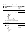
Description of Modes for Triggering of Sequencer/Frame and Profile
Acquisition
No.
Sequencer/Frame Trigger Mode
Profile Trigger Mode (PTM)
0
Free-run
PTM0 (free-run)
PTM1(IN1)
PTM2 (IN2)
PTM3 (RS422)
1
Start/stop over camera input 1 / 2
PTM0 (free-run)
Continuous frame acquisition is started with the rising edge
of camera input 1 (IN1) and stopped with rising edge of
PTM3 (RS422)
camera input 2 (IN2)
trigger start of sequencer
(frame trigger)
trigger stop of sequencer
t
When “stop” occurs, the frame is not transmitted
immediately over the GigE interface but the camera
continues to acquire profile data, until the predefined frame
height is reached.
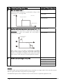
2
Start over camera input 1
PTM0 (free-run)
Single frame acquisition is triggered over the rising edge of
camera input 1 (IN1)
PTM2 (IN2)
PTM3 (RS422)
IN1
trigger start of sequencer
(frame trigger)
t
C4-1280-GigE Camera Hardware Reference Manual Rev. 1.8
• 39
No.
Sequencer/Frame Trigger Mode
Profile Trigger Mode (PTM)
3
Gate over camera input 1
PTM0 (free-run)
Continuous frame acquisition is performed as long as the
camera input 1 is on high state
IN1
PTM2 (IN2)
Gate Function
start trigger of sequencer
PTM3 (RS422)
stop trigger of sequencer
t
4
Start/stop with instant transmission over camera input 1 / 2
PTM0 (free-run)
Continuous frame acquisition is started with rising edge of
camera input 1 (IN1) and stopped with rising edge of
PTM3 (RS422)
camera input 2 (IN2)
trigger start of sequencer
(frame trigger)
trigger stop of sequencer
t
When “stop” occurs, the frame is transmitted immediately
over the GigE interface. Using the Chunk Data mode of C4
camera, it is possible to determine how many rows of the
frame contain valid data (see ChunkImageInfo for details).
5
AutoStart (no external signal is required)
PTM0 (free-run)
PTM1(IN1)
PTM2 (IN2)
PTM3 (RS422)
Remarks:
The above table (except AutoStart) applies also to acquisition in image mode. In this case the camera
delivers a gray scale sensor image for every profile trigger.
A detailed description of the AutoStart function can be found in a separate application note.
40 •
C4-1280-GigE Camera Hardware Reference Manual Rev. 1.8
The Chunk Data Mode of C4-1280-GigE
General Description
The C4-1280-GigE features a Chunk Data mode for providing additional information to the acquired
image data. The implementation of XML nodes is performed according to SFNC 1.4:
•
Category ChunkDataControl
•
ChunkModeActive
•
ChunkModeSelector (OneChunkPerFrame, OneChunkPerProfile)
The ChunkData generated by the camera have the following format:
•
ChunkImage
•
1…N x ChunkAcqInfo
•
ChunkImageInfo
Depending on camera mode (image or 3D) the ChunkData block („ChunkAcqInfo“) can be sent as
follows:
•
in image mode, the camera can send only one ChunkAcqInfo block per image frame.
•
in 3D mode, the camera can send one ChunkAcqInfo block either per 3D frame
(“OneChunkPerFrame”) or per 3D profile (“OneChunkPerProfile”).
The „ChunkImageInfo“ is the last ChunkData sent by the camera and contains following data:
•
number of valid rows in ChunkImage
•
number of valid ChunkAcqInfo blocks
•
flags identifing the current frame as „Start“ or „Stop“
The ChunkAcqInfo block consists of totally 32 bytes containing following data
•
64 bit timestamp
•
32 bit frame counter
•
32 bit trigger coordinate
•
Trigger status
•
I/O Status
•
reserved
The data of timestamp, frame counter, trigger coordinate, trigger status and I/O status are assigned at
the start of every image integration.
When ChunkMode is disabled, the camera uses the “regular“ GEV image protocol, in which the
optional transfer of frames with variable height and payload is supported.
C4-1280-GigE Camera Hardware Reference Manual Rev. 1.8
• 41
Furthermore, when ChunkMode is enabled, the camera sends the full payload, even if the
ChunkImage or ChunkAqInfo blocks contain partially valid data. The number of valid ChunkImage
rows and ChunkAqInfo blocks can be read from ChunkImageInfo.
For example, when in Start/Stop mode with instant frame transmission, the camera stops the frame
acquisition as soon as the stop trigger occurs and transfers the complete contents of internal image
buffer. Using the ChunkImageInfo data block, it is possible to detect how many image rows and
ChunkAqInfo blocks are valid in the payload buffer.
The tag of ChunkData has big endian byte order. The data of ChunkData has little endian byte order.
An endian converter for ChunkData is not supported.
Payload Layout in Chunk Data Mode
Chunk Image Data
GV_ChunkDescriptorData
for Image Data
N x GV_ChunkAcqInfo
GV_ChunkDescriptorData
for ChunkAcqInfo
GV_ChunkImageInfo
GV_ChunkDescriptorData
for ChunkImageInfo
42 •
C4-1280-GigE Camera Hardware Reference Manual Rev. 1.8
XML Descriptors and Id’s
ChunkImageInfo
<Port Name="FrameInfoPort">
<ChunkID>11119999</ChunkID>
</Port>
ChunkAcqInfo
<Port Name="CameraChunkPort">
<ChunkID>66669999</ChunkID>
</Port>
ChunkImage
<Port Name="ImageInfoPort">
<ChunkID>A5A5A5A5</ChunkID>
</Port>
C4-1280-GigE Camera Hardware Reference Manual Rev. 1.8
• 43
Chunk Data Structure
#pragma pack(push)
#pragma pack(1)
typedef struct _GV_ChunkAcqInfo
{
unsigned int
unsigned int
unsigned int
signed int
unsigned char
unsigned short
unsigned short
unsigned char
unsigned char
unsigned short
unsigned short
unsigned short
unsigned short
unsigned char
} GV_ChunkAcqInfo;
timeStamp64L;
// 0..3
timeStamp64H;
// 4..7
frameCnt; // 8..11
triggerCoord;
// 12..15
triggerStatus; // 16
DAC; // 17..18
ADC; // 19..20
INT_idx; // 21
AOI_idx; // 22
AOI_ys;
// 23..24
AOI_dy;
// 25..26
AOI_xs;
// 27..28
AOI_trsh; // 29..30
AOI_alg; // 31
#define CHUNKACQINFO_TRIGGERSTATUS_BIT_TRIGGER_OVERRUN 0x01
#define CHUNKACQINFO_TRIGGERSTATUS_BIT_RESOLVER_CNT_UP 0x02
#define
#define
#define
#define
CHUNKACQINFO_TRIGGERSTATUS_BIT_IN0
CHUNKACQINFO_TRIGGERSTATUS_BIT_IN1
CHUNKACQINFO_TRIGGERSTATUS_BIT_OUT0
CHUNKACQINFO_TRIGGERSTATUS_BIT_OUT1
0x10
0x20
0x40
0x80
typedef struct _GV_ChunkImageInfo
{
unsigned int mSizeYReal;
unsigned int numChunkAcqInfo;
unsigned int flag;
}
GV_ChunkImageInfo;
#define CHUNKIMAGEINFO_FLAG_BIT_START_FRAME 0x00000001
#define CHUNKIMAGEINFO_FLAG_BIT_STOP_FRAME 0x00000002
typedef struct _GV_ChunkDescriptor
{
unsigned int descriptor;
unsigned int length;
} GV_ChunkDescriptorData;
#pragma pack(pop)
44 •
C4-1280-GigE Camera Hardware Reference Manual Rev. 1.8
The GigE-Vision Events of C4-1280-GigE
The C4-1280-GigE supports a number of events that can be monitored by a software application by
means of a callback function. Events provide real time notification on various stages of the acquisition
sequence and data transfer.
Event Name
Event ID
Description
AcquisitionStart
36882
Frame Acquisition is started
AcquisitionEnd
36883
Frame Acquisition is terminated
TrasnferStart
36884
Frame transfer is started from the camera
TransferEnd
36885
Frame transfer is terminated
AoiTrackingOn
36886
The AOI tracking process is started and the laser line image is valid for
AOI alignment
AoiTrackingOff
36887
The AOI tracking process is stopped and the AOI position is not
updated anymore
AoiSearchFailed
36888
AOI-Search failed to detect the laser line
C4-1280-GigE Camera Hardware Reference Manual Rev. 1.8
• 45
C4-1280-GigE Camera Interface
The GigE Interface
Pin Nr.
GigE Signal Name
1
MX0+
2
MX0-
3
MX1+
4
MX1-
5
MX2+
6
MX2-
7
MX3+
8
MX3-
Shield
Shield
The I/O & Power Interface
Pin Nr.
Signal Name
Description
1
GND_EXT
main camera ground
2
VCC_EXT
camera supply voltage (10-24V DC)
3
RS232_RX
reserved
4
RS232_GND
reserved
5
ENC_A-
encoder Track1 RS422 reversible input (A- )
6
ENC_B-
encoder Track2 RS422 reversible input (B- )
7
OUT1
optoisolated Output1
8
OUT2
optoisolated Output2
9
IN1
optoisolated Input1
10
IN2
optoisolated Input2
11
GND_EXT
main camera ground
12
VCC_EXT
camera supply voltage (10-24V DC)
13
RS232_TX
reserved
14
ENC_GND
Encoder ground
15
ENC_A+
encoder Track1 RS422 none reversible input (A+)
16
ENC_B+
encoder Track2 RS422 none reversible input (B+ )
46 •
C4-1280-GigE Camera Hardware Reference Manual Rev. 1.8
Pin Nr.
Signal Name
Description
17
VCC_OUT
Power supply voltage of camera optoisolated outputs (5V/24V DC)
18
GND_OUT
Ground of camera optoisolated outputs
19
GND_IN1
GND for optoisolated Input1
20
GND_IN2
GND for optoisolated Input2
Shield
SHIELD
is connected to camera case
Part Numbers for I/O Connector MDR 20
Description
Part Number 3M
20-pin Connector
10120
lockable connector case
10320
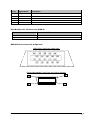
MDR20 I/O Connector Pin Assignment
Cable Plug: View from solder side:
Camera Receptable: View from rear side of camera:
10
20
C4-1280-GigE Camera Hardware Reference Manual Rev. 1.8
1
11
• 47
The Illumination Control
Pin Nr. Signal Name
Description
1
VCC_LASER
Output to power the illumination device (5V, max. 200mA, fused)
2
GND_LASER
Ground for illumination device
3
LASER_DOUT
Output for digital modulation of illumination device (TTL signal)
4
LASER_AOUT
Output for analog modulation of illumination device (0-5V DC)
5
LASER_AIN
Input for monitoring specific functions of illumination device (0-5V DC)
3
2
4
1
5
Part Number for Illumination Control Connector
Description
Part Number Binder Series 712
M9 5-pin male connector, EMV
protected
99-0413-10-05
M9 5-pin male connector 90° angled,
EMV protected
99-0413-75-05
48 •
C4-1280-GigE Camera Hardware Reference Manual Rev. 1.8
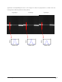
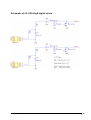
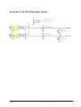
Schematic of C4-1280-GigE digital inputs
C4-1280-GigE Camera Hardware Reference Manual Rev. 1.8
• 49
Schematic of C4-1280-GigE digital outputs
50 •
C4-1280-GigE Camera Hardware Reference Manual Rev. 1.8
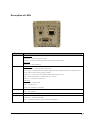
Description of LEDs
LED
1 (PWR)
Description
During boot:
Green On = FPGA configuration done
Red On = Loader Stop. Boot failed. No valid Image could be loaded.
After boot:
Green On= Boot completed
2 (USR)
During boot:
Green fast blink = boot procedure takes places
Green blink = Configuration Error, FPGA configuration failure. Boot procedure is repeated up to 3
times, after which the Factory-Image is loaded.
Green On = camera start up completed, FPGA configuration success
Off = FPGA configuration successful after error recovery
Red On = a boot error has occurred
After boot:
Red On= no network found
Off = network found
Green On=CCP status connected
3 (LSR)
On = Laser is ON
4 (GigE_left)
Green blink = Indication of network activity
5 (GigE_right)
Green On = Linkspeed 1 Gbit
Off = Laser is OFF
Yellow On = Linkspeed 100 Mbit
Off = Linkspeed 10 Mbit or wait for end of autonegotiation
C4-1280-GigE Camera Hardware Reference Manual Rev. 1.8
• 51
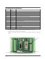
Integrated RS232 serial interface and Camera Boot Log
During boot procedure, the camera outputs a log via the integrated RS232 serial interface. The
external C4-I/O-Panel provides a D-sub 9-pin male socket for monitoring the boot log. A null-modem
cable (crosslinked) must be used to connect the C4-I/O-Panel to a host PC. The parameters of the
serial communication are listed as follows:
Baudrate
115200
Data bits
8
Parity
None
Stopbits
1
Handshake
None
Sample camera boot log
**************************************
MCB InitDone. (WaitClks 75203(84466))
Bootloader(build Mar 6 2012, 08:25:53)
Executing program starting at address: 0x50000000
**************************************
00004700 ms: Camera start.
------------------------------------------Start HardwareInit.
Reset sensor to defaults.
Reset sensor.
PLL sensor.
Wait PLL locked. Locked.
StreamAlignLupa done(0x032A).
Current stream delay values.
-24 37 -30 -31 -30 31 -28 29 32 30 -31 -33 -23
------------------------------------------Ready to start GEV.
00004743 ms: Start system monitoring.
Stack info: Current Stack position changed to 0x00001F98.
00004752 ms: Load Bootstrap registers.
00004755 ms: **************************************
00004759 ms: Camera type: 1280
00004762 ms: Model: C4_1280_GigE
00004765 ms: MAC: 0-50-C2-8E-D0-74
52 •
C4-1280-GigE Camera Hardware Reference Manual Rev. 1.8
00004768 ms: Serial Number: 20502217
00004772 ms: Device Version: 2.0.0
00004775 ms: Firmware Version: 1.4.1
00004778 ms: Application build: Development 1.4.0.2374 - Fri Mar 16 09:07:23 2012
00004786 ms: LwIP build: Patched LwIp 1.30 Mar 16 2012, 08:55:33
00004791 ms: Installed Modules:
00004794 ms: File: C4_1280_GigE_1.3.4.zip, Rev.: 1030400, Device: 1, Length: 2274949
00004808 ms: File: Bitstreamfb.bin, Rev.: 1000000, Device: 1, Length: 2453092
00004815 ms: File: 1280S6.srec, Rev.: 1040000, Device: 1, Length: 742770
00004821 ms: File: 1280S6.srec, Rev.: 1000000, Device: 1, Length: 697386
00004828 ms: GEV Version 1.1
00004830 ms: XML-URL1: Local:C4_1280_GigE_1.3.4.zip;8C400904;58DD
00004836 ms: XML-URL2: http://www.automationtechnology.de/genicam/C4_1280_GigE_1.3.4.zip
00004844 ms: IP config mode:
00004846 ms: Persistent IP
00004849 ms: IP: 169.254.64.2
00004851 ms: Netmask: 255.255.0.0
00004854 ms: Gateway: 0.0.0.0
00004857 ms: LLA always ON.
00004860 ms: **************************************
auto-negotiated link speed: 1000
00004896 ms: Wait for end of IP configuration...
00004899 ms: Start IP configuration with persistent IP
00004904 ms: Enable hw InterPacketDelay.
00004908 ms: Network interface is up, speed: 1000 Mbps
00004913 ms: IP:
169.254. 64. 2
00004916 ms: Netmask: 255.255. 0. 0
00004919 ms: Gateway: 0. 0. 0. 0
00004923 ms: Assigned from static address
C4-1280-GigE Camera Hardware Reference Manual Rev. 1.8
• 53
The External C4 I/O Panel
Clamp Pin
Nr.
Signal
Name
Description
P1 / 1
SCHIELD
camera shield
P1 / 2
GND_EXT
camera ground
P1 / 3
VCC_EXT
camera supply voltage (7-24V DC)
P2 / 1
ENC_B-
encoder Track2 RS422 reversible input (B- )
P2 / 2
ENC_B+
encoder Track2 RS422 none reversible input (B+ )
P2 / 3
ENC_A-
encoder Track1 RS422 reversible input (A- )
P2 / 4
ENC_A+
encoder Track1 RS422 none reversible input (A+ )
P2 / 5
ENC_GND
encoder ground is connected to camera ground
P4 / 1
GND_IN2
GND for optoisolated Input2
P4 / 2
IN2
optoisolated Input2
P4 / 3
GND_IN1
GND for optoisolated Input1
P4 / 4
IN1
optoisolated Input1
P4 / 5
OUT1
optoisolated Output1
P4 / 6
OUT2
optoisolated Output2
P4 / 7
GND_OUT
Ground of camera optoisolated outputs
P4 / 8
VCC_OUT
Power supply voltage of camera optoisolated outputs (5V/24V DC)
-
the optoisolated inputs of the C4 I/O panel can be operated with 5V or 24 V DC
-
the panel features a 2A fuse for camera protection
-
in order to avoid signal noise, do not connect the main ground GND_EXT to other GND
signals
P1/1
P4/1
54 •
P2/1
C4-1280-GigE Camera Hardware Reference Manual Rev. 1.8
Mechanical Dimensions (mm)
58
90
48
Weight of C4-I/O-Panel: 50 g
Mount for DIN rail assembly
C4-1280-GigE Camera Hardware Reference Manual Rev. 1.8
• 55
Service Information
Document Revision
Rev. Nr.
1.0
1.1
Date
05.01.2009
13.05.2009
1.2
1.3
1.4
1.5
1.6
1.7
1.8
27.05.2009
03.12.2009
12.02.2010
05.10.2010
05.03.2011
05.01.2012
13.08.2012
Modification
First version
Added mechanical drawings, information about I/O panel, I/O cable.
Updated GenICam file description.
Update I/O panel image
Update GenICam Features
Update GenICam Features, Trigger Modes, Specification
Update GenICam Features, Trigger Modes, Chunk Data Mode
Minor corrections, added I/O schematics
Update CXC file, GEV Events, Dataout structure
New XML registers, GEV Events, dimensions C4-I/O-Panel, minor additions
and corrections
Product Information and Updates
Updates
www.AutomationTechnology.de
Service and Support
[email protected]
In order to process your support inquiries immediately, we always need the serial number of the
camera, a dump of configuration EEPROMs, a snapshot and a precise problem description.
Product Inquiries and Price Quotations
[email protected]
C4-1280-GigE Camera Hardware Reference Manual Rev. 1.8
• 57
Warranty Conditions
Only the manufacturer can recognize the conditions of warranty. Should other parties than the
manufacturer be responsible for the malfunctioning, we consider the right of warranty as void. This is
the case if the unit is modified electrically or mechanically, particularly in its wiring/soldering, or if the
unit is used for purposes not intended by the manufacturer, or if the unit's external wiring is faulty, or if
the unit is used under conditions outside those stated in its manual.
58 •
C4-1280-GigE Camera Hardware Reference Manual Rev. 1.8