1
FORM 160.81-EG2 (511)
Guide Specifications
tomatically remove oil which may have migrated to the
evaporator and return it to the compressor. The oil separator shall be of a vertical design with no moving parts,
and shall provide high-efficiency oil separation before
the refrigerant enters the heat exchangers. The oil separator shall be designed, tested and stamped in accordance
with ASME Boiler and Pressure Vessel Code, Section
VIII – Division 1.
Motor
The motor shall be 2-pole, continuous duty, cage induc-tion
type, and shall utilize suction gas cooling (semi-hermetic
design). Motor full-load amperes at design conditions
shall not exceed motor nameplate (FLA). Motor shall be
designed for use with the type starter specified.
For units utilizing remote electromechanical starters, a
large steel terminal box with gasketed front access cover
shall be provided for field connected conduit. Overload/
overcurrent transformers shall be furnished with all units.
(For units furnished with factory packaged Solid State
Starters, refer to the “Options” section.)
Evaporator
Evaporator shall be of the shell-and-tube, flooded type
designed for 235 psig (1620 kPa) working pressure on
the refrigerant side. Shell shall be fabricated from rolled
carbon steel plate with fusion welded seams or carbon
steel pipe; have carbon steel tube sheets, drilled and
reamed to accommodate the tubes; and intermediate
tube supports spaced no more than four feet apart. The
refrigerant side shall be designed, tested and stamped
in accordance with ASME Boiler and Pressure Vessel
Code, Section VIII – Division 1. Tubes shall be highefficiency, internally enhanced type. Each tube shall be
roller expanded into the tube sheets providing a leakproof seal, and be individually replaceable. Water velocity through the tubes shall not exceed 12 FPS (3.6 m/s).
Liquid level sight glass shall be located on the side of
the shell to aid in determining proper refrigerant charge.
The evaporator shall have a refrigerant relief device to
meet the requirements of ASHRAE 15 Safety Code for
Mechanical Refrigeration.
Water boxes shall be removable to permit tube cleaning and replacement. Stubout water connections having Victaulic grooves shall be provided. Water boxes
shall be designed for 150 psig (1034 kPa) design working
pressure. Vent and drain connections with plugs shall be
provided on each water box.
48
Condenser
Condenser shall be of the shell-and-tube type, designed
for 235 psig (1620 kPa) working pressure on the refrigerant side. Shell shall be fabricated from rolled carbon steel
plate with fusion welded seams or carbon steel pipe; have
carbon steel tube sheets, drilled and reamed to accommodate the tubes; and intermediate tube supports spaced
no more than four feet apart. A refrigerant subcooler shall
be provided for improved cycle efficiency. The refrigerant
side shall be designed, tested and stamped in accordance
with ASME Boiler and Pressure Vessel Code, Section
VIII – Division 1. Tubes shall be high-efficiency, internally
enhanced type. Each tube shall be roller expanded into the
tube sheets providing a leak-proof seal, and be individually replaceable. Wa-ter velocity through the tubes shall
not exceed 12 FPS. The condenser shall have refrigerant
relief device to meet the requirements of ASHRAE 15
Safety Code for Mechanical Refrigeration.
Water boxes shall be removable to permit tube cleaning and replacement. Stubout water connections having Victaulic grooves shall be provided. Water Boxes
shall be designed for 150 psig (1034 kPa) design working
pressure. Vent and drain connections with plugs shall be
provided on each water box.
Refrigerant System
The YR chiller is equipped with a refrigerant metering device
consisting of a fully modulating variable orifice controlled via
the OptiView Control Center. This control ensures proper
refrigerant flow to the evaporator over a wide range of operating conditions, including thermal storage applications
and chilled water reset. Valve operation is programmable
and can be customized for a specific application via the
OptiView Control Center keypad.
The condenser shell shall be capable of storing the
entire system refrigerant charge during servicing. Isolation from the rest of the system shall be by manually
operated isolation valves located at the inlet to the oil
separator and outlet of the condenser (isolation valves
optional). Additional valves shall be provided to facilitate removal of refrigerant charge from the system.
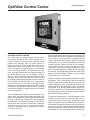
OPTIVIEW CONTROL CENTER
General – The chiller shall be controlled by a stand-alone
microprocessor based control center. The chiller control
panel shall provide control of chiller operation and monitoring of chiller sensors, actuators, relays and switches.
JOHNSON CONTROLS