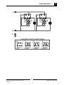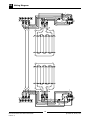
1
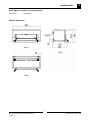
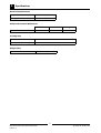
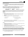
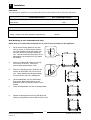
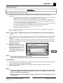
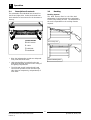
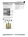
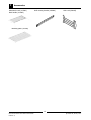
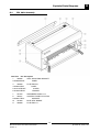
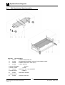
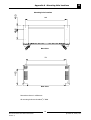
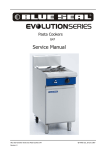
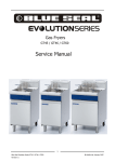
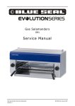
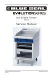
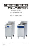
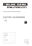
Electric Salamanders
E91
Service Manual
Blue Seal Evolution Series Electric Salamander
Revision 1/
© Moffat Ltd, January 2007
WARNING:
ALL INSTALLATION AND SERVICE REPAIR WORK MUST BE CARRIED OUT BY
QUALIFIED PERSONS ONLY.
IMPORTANT: MAKING ALTERATIONS MAY VOID WARRANTIES AND APPROVALS.
Blue Seal Evolution Series Electric Salamander
Revision 1/
© Moffat Ltd, January 2007
Contents
This manual is designed to take a more in depth look at the E91 Salamander for the purpose of
making the units more understandable to service people.
There are settings explained in this manual that should never require to be adjusted, but for completeness
and those special cases where these settings are required to change, this manual gives a full explanation
as to how, and what effects will result.
Section
Page Number
1. Specifications............................................................................................1
2. Installation................................................................................................3
3. Operation...................................................................................................6
3.1 Description
3.2 Racking
4.
of Controls
Cleaning / Maintenance............................................................................7
5. Trouble-shooting Guide.............................................................................8
6. Service
Procedures....................................................................................9
6.1 Access
6.2 Replacement
7. Accessories..............................................................................................12
8. Exploded
9. Circuit
Parts Diagrams........................................................................13
Schematic.....................................................................................15
10. Wiring Diagram........................................................................................16
11. Service Contacts......................................................................................17
Appendix A. Mounting Hole Locations...........................................................19
Blue Seal Evolution Series Electric Salamander
Revision 1/
© Moffat Ltd, January 2007
Blue Seal Evolution Series Electric Salamander
Revision 1/
© Moffat Ltd, January 2007
Specifications
1
Model Numbers Covered in this Specification
E91 Electric
Salamander
External Dimensions
Front
Side
Plan
1
Blue Seal Evolution Series Electric Salamander
Revision 1/
© Moffat Ltd, January 2007
1
Specifications
Electrical Requirements
Voltage
220-240Vac, 1P+N+E
Power (@ 240Vac)
6.0 kW, 25A
Salamander Internal Dimensions
E91
Width
Depth
685 mm
330 mm
Height
230 mm
(at front)
Cooking Area
Rack Size
610mm x 310mm
Branding Plate (accessory)
610mm x 310mm
Weight (Net)
E91
41kg
2
Blue Seal Evolution Series Electric Salamander
Revision 1/
© Moffat Ltd, January 2007
Installation
2
Installation Requirements
NOTE: It is most important that this salamander is installed correctly and that operation is
correct before use. Installation shall comply with local electrical, health and safety
requirements.
Blue Seal Salamanders are designed to provide years of satisfactory service, and correct installation is
essential to achieve the best performance, efficiency and trouble-free operation.
This appliance must be installed in accordance with National installation codes and in addition, in
accordance with relevant National / Local codes covering electrical and fire safety.
Australia / New Zealand
United Kingdom:
AS/NZS3000
BS 7671
- Wiring Rules.
- Requirements for Electrical Installations.
Installations must be carried out by authorised persons only. Failure to install equipment to
the relevant codes and manufacturer’s specifications shown in this section will void the
warranty.
Unpacking
1.
2.
3.
Remove all packaging and transit protection from the appliance including all protective plastic
coating from the exterior stainless steel panels.
Check equipment and parts for damage. Report any damage immediately to the carrier and
distributor.
Check that the following parts have been supplied with the Salamander:
1 x Salamander Rack.
1 x Wall Mounting Bracket, including;
1 x Crumb Tray.
- 2 x 25mm Black Plastic Spacers.
- 2 x 3/8” Bolts / Nuts.
4.
5.
Report any deficiencies to the distributor who supplied the unit.
Check that the available electrical supply is correct to that shown on the rating plate located on the
front bottom corner of the right hand side panel.
Location
1.
This appliance must be mounted onto a non-combustible wall or tailored stand, using the rear wall
bracket and spacing screws provided.
2.
Combustible walls must not protrude past the front of the appliance.
3.
This appliance must not be mounted on a combustible surface or metal surface, as radiated heat will
cause these surfaces to become extremely hot.
4.
Caution should be taken as intense heat is emitted at the bottom front of the appliance.
5.
The unit should be mounted under an extraction hood in compliance with all local regulations.
In the event that the unit is not mounted under an extraction hood, the installer must ensure
that all regulations are met and that there is an unobstructed minimum distance of 750 mm
from the top surface of the unit to the ceiling, which must be of non-combustible material.
NOTE: Do not obstruct or block the appliances flue. Never directly connect a ventilation
system to the appliance flue outlet.
3
Blue Seal Evolution Series Electric Salamander
Revision 1/
© Moffat Ltd, January 2007
2
Installation
Clearances
This unit must be installed on a non-combustible wall or tailored stand with the following clearances:Combustible Surface
Left/Right hand side
Non-Combustible Surface
50mm
0mm
Rear 50mm
0mm
Top Clearance to;
Extraction Hood
200mm
Ceiling (subject to all local regulation requirements)
300mm
Wall Mounting (to non-combustible wall only)
NOTE: Only non-combustible materials can be used in close proximity to this appliance.
1.
Fix the wall mounting bracket to the wall
with six screws, in such a position that the
top of the bracket is level and at least 945
mm (38”) above any surface beneath the
unit. This will ensure that the bottom of the
Salamander is at least 600 mm (24”) above
any surface.
2.
Fit the two black plastic spacers to the top
rear corners of the unit. Leave them
unscrewed by approximately 5 mm.
3.
Fit the two adjusting screws / bolts into the
nutserts at the bottom rear corners of the
unit. These should protrude approximately
30 mm from the rear of the Salamander.
~ 5mm
~30mm
4.
Lift the Salamander onto the wall bracket,
lining up the black plastic spacers on the
salamander with the mounting notches in the
bracket.
5.
Lower the Salamander onto the mounting bracket.
6.
Tighten the black spacers securely and adjust the
levelling screws/bolts to ensure that the unit is level.
4
Blue Seal Evolution Series Electric Salamander
Revision 1/
© Moffat Ltd, January 2007
Installation
2
Electrical Connection
WARNING:
THIS
APPLIANCE MUST BE EARTHED.
IF
THE SUPPLY CORD IS DAMAGED , IT MUST BE REPLACED BY A SUITABLY
QUALIFIED PERSON IN ORDER TO AVOID A HAZARD.
When connecting a Blue Seal electric appliance to the main supply, ensure that the following is
carried out:• An isolating switch is fitted within 2 m of the appliance, but not on the appliance and in such a
position that the user does not have to reach across the cooking surface.
• Supply cord shall be oil-resistant, sheathed flexible cable and not lighter than ordinary polychloroprene or other equivalent synthetic elastomer sheathed cord (as per AS/NZS 3191 part
2.10.11. or IEC 60245-IEC-57) e.g. HO5 RN-F Type.
• The branch supply line shall be individually overload protected to the correct current rating and
the supply chord shall be protected against any mechanical or thermal damage.
• A grommet is fitted around the wiring entry hole into the appliance.
• All wiring connections must be tight.
Refer to the appropriate wiring standards for the size of cable that is to be supplied to an appliance for
the current drawn on that line.
NOTE: ALL ELECTRICAL CONNECTIONS MUST ONLY BE CARRIED OUT BY AN AUTHORISED PERSON.
1.
Remove either the left or right hand side panel to allow access to the electrical connection terminal block.
Fit the cable through the small grommet located at the rear of the unit and connect to the terminals as
marked.
2.
If required, the appliance can be connected to two 13 or 15 amp single phase supplies by removing the
insulated wire loom between the left and right hand terminal blocks. Independent supplies can then be
connected to each side.
3. The operating voltage of the
salamander is stated on the rating
plate affixed to the right hand side
panel front bottom corner. This information is also shown in the
“Specifications” Section of this manual. Ensure that the available voltage is correct.
NOTE:
Rating Plate
• This appliance must be grounded / earthed.
• Fixed wiring installations must incorporate an all-pole disconnection switch.
Commissioning
1.
Before leaving the new installation, check that all the connections are correct and, and that the unit functions in accordance with the operating instructions.
2.
Check the current draw and loading for the equipment. Refer specification section for correct
electrical requirements.
NOTE:
• If for some reason it is not possible to get the unit to operate correctly, turn off the elec-
trical power supply and contact a qualified service person. The supplier of this unit will be
able to recommend a suitable person.
• Make sure that the electrical supply is turned off before any service or maintenance work
is carried out.
5
Blue Seal Evolution Series Electric Salamander
Revision 1/
© Moffat Ltd, January 2007
3
Operation
3.1
Description of controls
3.2
The salamander has individual heat controls for
the left and right sides. Select the desired heat
level and allow a few minutes for the elements to
heat up.
Racking
Racking System
The Rack System fitted to the Blue Seal
Salamander is self-supporting when withdrawn,
to allow easy loading of food. The installation of
the rack is dependant on the cooking function
required.
Control Knobs
With Branding Plate
0 OFF Position
1 LOW
2 MEDIUM
3 MAXIMUM
•
Blue Seal salamanders provide two independently controlled heat zones.
•
High speed grilling is provided by the two
high speed infrared elements in the ceiling of
the grilling compartment.
•
The left hand control knob and right hand
control knob operate the left side and right
side elements respectively, independently of
each other.
Without Branding Plate
6
Blue Seal Evolution Series Electric Salamander
Revision 1/
© Moffat Ltd, January 2007
Cleaning / Maintenance
4
Caution:
ALWAYS TURN OFF THE GAS SUPPLY BEFORE CLEANING.
THIS UNIT IS NOT WATER PROOF.
DO NOT USE WATER JET SPRAY TO CLEAN INTERIOR OR EXTERIOR OF THIS UNIT.
4.1
Cleaning
General
Stainless surfaces
To achieve the best results, cleaning must be
thorough, and all controls and mechanical parts
checked and adjusted periodically by a competent
serviceman. If any small faults occur, have them
attended to promptly.
Clean with detergent. Baked on deposits or
discolouration may require a good quality
stainless steel cleaner or stainless steel wool.
Always apply the cleaner when the Salamander is
cool and rub in the direction of the "grain".
Don't wait until they cause a complete
breakdown.
Enamelled surfaces
Do not use wire brushes, steel wool or other
abrasive material. Clean the enamelled surfaces
regularly with a good quality domestic oven
cleaner. Remove the rack and side racks from
the Salamander - this allows easy cleaning of the
flat enamelled side walls. Leave the tray in to
collect all residue.
Racking
For ease of cleaning of this unit and the racking
system and to achieve the best results, it is recommended that the racking is removed
completely from the unit and cleaned
independently This will allow for a more
thorough cleaning of the Salamander.
To remove the racking system, carry out the
following instructions.
Grease / Crumb Tray
Empty and clean daily.
Remove the Grease / Crumb Tray from the
underside of the salamander unit.
Remove the Branding Plate from the rack (If
fitted).
Slide the rack out of the side racks and remove
from the unit.
Remove the left and right hand side racks from
the unit by removing the single securing screw
from each of the side racks.
Withdraw the left and right hand side racks from
the unit.
Refit the Racking in the reverse order once cleaning has been completed.
7
Blue Seal Evolution Series Electric Salamander
Revision 1/
© Moffat Ltd, January 2007
5
Trouble-shooting
WARNING:
ALL INSTALLATION AND SERVICE REPAIR WORK MUST BE CARRIED OUT BY
QUALIFIED PERSONS ONLY.
Fault
Possible cause
The unit does not operate (neither The mains isolating switch on the
element works)
wall, circuit breaker or fuses are
“off” at the power board.
One element does not work
or,
One element coil does not work
Indicator light does not illuminate
Remedy
Turn on.
Incorrect electrical supply.
Ensure electrical supply correct.
Selector switch on unit faulty.
Check switch poles - replace if
faulty.
(Refer service section 6.2.2)
Element faulty (blown).
Replace.
(Refer service section 6.2.1)
Indicator faulty.
Replace.
(Refer service section 6.2.3)
8
Blue Seal Evolution Series Electric Salamander
Revision 1/
© Moffat Ltd, January 2007
Service Procedures
Section
6
Page no.
6.1 Access ....................................................................................................10
6.1.1
6.1.2
Control Panel...........................................................................................................10
Side Panel...............................................................................................................10
6.2 Replacement ..........................................................................................10
6.2.1
6.2.2
6.2.3
Element..................................................................................................................10
Selector Switch........................................................................................................11
Indicator Light.........................................................................................................11
ALL INSTALLATION AND SERVICE REPAIR WORK MUST BE CARRIED OUT BY
QUALIFIED PERSONS ONLY.
WARNING:
ENSURE GAS SUPPLY IS SWITCHED OFF BEFORE SERVICING
ALWAYS CHECK / TEST FOR GAS LEAKS AFTER SERVICE REPAIRS ON THE GAS
SYSTEM
9
Blue Seal Evolution Series Electric Salamander
Revision 1/
© Moffat Ltd, January 2007
6
Service Procedures
6.1
Access
6.2
Replacement
6.1.1 Front panel
6.2.1 Element
1) Remove selector knob by pulling firmly away
from control panel.
1) Remove trays and racks from unit.
2) Remove the relevant side panel by removing
the two screws located towards the bottom of
the applicable side.
2) Undo two screws at the bottom of control
panel. Drop control
down to access
components.
4) Remove wires from the element terminals.
3) Undo the two screws securing the selector
switch to the control panel.
5) Loosen the element support thumb-screw
(located at the front centre of the
salamander).
4) Remove the two wires to the indicator light.
Panel can now be removed.
Slide the element support forward to release
it from the thumbscrew.
6) Undo the two M5 self-clinching nuts
securing the element to the inside wall of the
salamander. Take care not to lose the
element springs.
Selector switch
securing screws
Control panel
screws
Figure 6.1.1
6.1.2 Side
panel
1) Remove two screws from bottom front of
panel.
Figure 6.2.1
7) Replace the element and reassemble in
reverse order.
2) Remove side panel by hinging out from
bottom and lift out.
NOTE: Correct element resistances (±5%):
Inner Coil:
Outer Coil:
30 ohms (1900W)
52 ohms (1100W)
Two screws
Figure 6.1.2
10
Blue Seal Evolution Series Electric Salamander
Revision 1/
© Moffat Ltd, January 2007
Service Procedures
6
6.2.2 Selector switch
6.2.3 Indicator light
1) Remove the selector knob by pulling firmly
away from the control panel.
1) Undo the two screws at the bottom of the
control panel. Drop the control panel down
to access components.
2) Undo the two screws at the bottom of the
control panel. Drop the control panel down to
access components.
2) Remove the wires from the rear of the neon.
3) From rear push neon through front of panel
rotating clockwise.
3) Undo the two screws securing the selector
switch to the control panel.
4) Push new neon in from front of panel, and
reconnect wires.
5) Replace control panel.
Selector switch
securing screws
Control panel
screws
Figure 6.2.2a
4) Transfer the wires to the new selector switch,
and secure to control panel with two screws.
5) Replace selector knob and control panel.
NOTE: Correct switch operation:
0123
OFF
700W 1900
3000
Selector switch
Figure 6.2.2b
11
Blue Seal Evolution Series Electric Salamander
Revision 1/
© Moffat Ltd, January 2007
7
Accessories
Salamander rack (017963)
Rack handle (013395)
Wall mounting bracket (026096)
Side rack (026093)
Branding plate (013418)
12
Blue Seal Evolution Series Electric Salamander
Revision 1/
© Moffat Ltd, January 2007
Exploded Parts Diagrams
8.1
8
E91 Main Assembly
Item Part No. Description
1
026096
WALL MOUNTING BRACKET
2 026086 BACK
3
026090
4 026094 SIDE
5 227476 FRONT
6 227963 NEON
PANEL
FLUE END RH
PANEL
COVER
ORANGE
7
227394
KNOB BSEAL 6MM 1-2-3
8
005017
CONTROL PANEL ELECTRIC
9 026091 TRAY
SUPPORT
10
227960
BLUE SEAL BADGE
11
026089
FLUE END LH
13
Blue Seal Evolution Series Electric Salamander
Revision 1/
© Moffat Ltd, January 2007
8
Exploded Parts Diagrams
8.2
E91 Electrical and Rack Assemblies
Item Part
No. Description
12
026114
ELEMENT SUPPORT WA
13
013920
SALAMANDER ELEMENT SUPPORT SECURING SCREW
14
026088
ELEMENT 3KW DUAL COIL (Ø6.5)
15
017682
3 HEAT SWITCH
16 026160 TERMINAL
17 026161 CABLE
18
026093
19 013395 RACK
20
227961
BLOCK
CLAMP
SIDE RACK WA - SALAMANDER
HANDLE
SIDE RACK SCREW
21 017963 RACK
22
227950
TROUGH TRAY WA
14
Blue Seal Evolution Series Electric Salamander
Revision 1/
© Moffat Ltd, January 2007
Circuit Schematics
9
L1
1900W
OUTER
1100W
P1 P2
2 3 4
1900W
OUTER
1100W
P1 P2
2 3 4
N
E
0
CONTROL SWITCH SETTINGS
1
2
3
OFF
750W
1900W
3000W
15
Blue Seal Evolution Series Electric Salamander
Revision 1/
© Moffat Ltd, January 2007
Wiring Diagram
P1
2
P2
3
6
P1
P2
2
3
17
7
9
8
4
22
18
16
21
6
21
15
15
22
14
5
5
14
20
1
4
10
19
12
4
2
19
13
20
3
1
10
11
10
16
Blue Seal Evolution Series Electric Salamander
Revision 1/
© Moffat Ltd, January 2007
Service Contacts
11
Australia
VICTORIA - MOFFAT PTY
HEAD OFFICE AND MAIN WAREHOUSE
740 Springvale Road
Mulgrave VIC 3170
Spare Parts Department
Tel (03) 9518 3888
Fax (03) 9518 3838
Free Call 1800 337 963
Fax (03) 9518 3895
NEW SOUTH WALES - MOFFAT PTY
Unit 3/142 James Ruse Drive
Rosehill
NSW 2142
Spare Parts
Tel (02) 8833 4111
Free Call 1800 337 963
Fax (03) 9518 3895
QUEENSLAND - MOFFAT PTY
30 Prosperity Place
Geebung QLD 4034
Spare Parts
Tel (07) 3630 8600
Free Call 1800 337 963
Fax (03) 9518 3895
WESTERN AUSTRALIA - MOFFAT PTY
67 Howe St
Osbourne Park, WA 6017
Spare Parts
Tel (08) 9202 6820
Fax (08) 9202 6836
Free Call 1800 337 963
Fax (03) 9518 3895
NATIONAL COVERAGE FOR 24 HOUR SERVICE OR MAINTENANCE DIAL
FREE CALL 1800 622 216 (AUSTRALIA ONLY)
Canada
SERVE
CANADA
22 Ashwarren Rd
Downview Fax
Ontario
M3J1Z5
Tel 416-631-0601
416-631-0315
New Zealand
CHRISTCHURCH - MOFFAT LTD
16 Osborne St
PO Box 10-001
Christchurch
Spare Parts
Tel (03) 389 1007
Fax (03) 389 1276
Free Call 0800 MOFFAT
(0800 66 33 28)
Fax (03) 381 3616
AUCKLAND - MOFFAT LTD
4 Waipuna Road
Mt Wellington
Auckland
Spare Parts
Tel (09) 574 3150
Fax (09) 574 3159
Free Call 0800 MOFFAT
(0800 66 33 28)
17
Blue Seal Evolution Series Electric Salamander
Revision 1/
© Moffat Ltd, January 2007
11
Service Contacts
United Kingdom
Utensils Direct
0845 873 6600
www.utensilsdirect.co.uk
18
Blue Seal Evolution Series Electric Salamander
Revision 1/
© Moffat Ltd, January 2007
Appendix A : Mounting Hole locations
A
80
Mounting hole locations
206
206
80
808
808
Base view
325
325
772
772
Rear view
Dimensions shown in millimetres.
All mounting holes are threaded 3/8” BSW
19
Blue Seal Evolution Series Electric Salamander
Revision 1/
© Moffat Ltd, January 2007