1
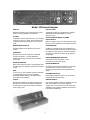
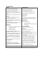
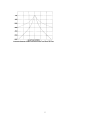
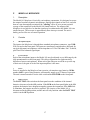
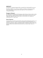
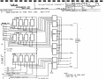
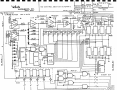
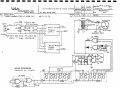
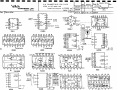
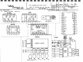
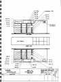
5 January 2005 – This contact update page has been added to the
Acrobat document you have downloaded. Please disregard any contact
information printed within the document.
Our Mailing and Shipping Address:
White Instruments Div. C Van R, Inc.
1514 Ed Bluestein Blvd., Suite 201 (for U.S. Mail)
Austin, TX 78721 U.S.A.
Phone: 512-389-5358
Fax: 512-301-3932
Main Email Address: [email protected]
World Wide Web Site: http://www.whiteinstruments.com/
Note: Repairs and packages should be shipped to Suite 202
Model 140
Sound Analyzer
Model 140 Sound Analyzer................................................................................................. 3
Specifications ...................................................................................................................... 4
Model 140 Sound Analyzer - Users' Manual ...................................................................... 6
A.
UNPACKING AND INSTALLATION.................................................................. 6
B.
INTRODUCTION.................................................................................................. 7
1.
Description .......................................................................................................... 7
2.
Applications Summary........................................................................................ 7
C.
CONTROL FUNCTIONS....................................................................................... 9
1.
Power................................................................................................................... 9
2.
Noise Level ......................................................................................................... 9
3.
Noise Output ....................................................................................................... 9
4.
Microphone Input................................................................................................ 9
5.
Line Input ............................................................................................................ 9
6.
dB-SPL................................................................................................................ 9
7.
Display (-dB)..................................................................................................... 10
8.
Display Range ................................................................................................... 10
9.
Overload ............................................................................................................ 10
D.
OPERATING INSTRUCTIONS AND APPLICATIONS ................................... 11
1.
General .............................................................................................................. 11
2.
Operation From the "Microphone" Input........................................................ 11
3.
Operation From the "Line" Input..................................................................... 12
4.
Overload Indicator............................................................................................. 12
5.
Over-Range on the Display............................................................................... 12
6.
Equalization of a Sound Reinforcement System................................................... 13
7.
Adjustment of Masking Noise Systems ............................................................ 14
8.
Rear Panel connections ..................................................................................... 14
a.
LINE AMP IN............................................................................................... 14
1
b.
PRE-AMP OUT ............................................................................................ 14
c.
COMMON .................................................................................................... 15
d.
REMOTE ...................................................................................................... 15
e.
SYNC ............................................................................................................ 15
f.
NOISE OUT.................................................................................................. 15
E.
MAINTENANCE AND REPAIRS ...................................................................... 16
F.
MODEL 141 MICPLEXOR.................................................................................. 17
1.
Description ........................................................................................................ 17
2.
Controls ............................................................................................................. 17
3.
a.
Microphone Inputs ........................................................................................ 17
b.
Level Controls ............................................................................................... 17
c.
Power............................................................................................................. 17
d.
Battery Check................................................................................................ 17
e.
MULTIPLEX-SINGLE Function ................................................................. 18
f.
MIC. SELECT Switch................................................................................... 18
g.
Output Connector .......................................................................................... 18
Operation........................................................................................................... 18
WARRANTY................................................................................................................ 19
Damage in Shipment ..................................................................................................... 19
Return Shipment............................................................................................................ 19
140 Preamp and Overload Schematic ............................................................................... 20
140 Filter Schematic.......................................................................................................... 21
140 Multiplexer Schematic ............................................................................................... 22
140 Control Section Schematic ......................................................................................... 23
140 Light Board Schematic............................................................................................... 24
140 Power Supply and Noise Source Diagrams................................................................ 25
Pin Connections for Chips - 1 of 2.................................................................................... 26
Pin Connections for Chips - 2 of 2.................................................................................... 27
140 Calibration Pot Locations........................................................................................... 28
2
Model 140 Sound Analyzer
DISPLAY
APPLICATIONS
Brilliant LED display gives a graphic point by point
readout. Clearly readable from a distance.
The Model 140 has many applications as a REAL
TIME SPECTRUM ANALYZER in the audio
frequency range.
FILTERS
SOUND REINFORCEMENT SYSTEMS
EQUALIZATION
27 double tuned 1/3 octave filters on I.S.O. standard
centers from 40 Hz to 16 kHz. Filters double tuned
for greater selectivity and rejection of out-of-band
noise.
Real time analysis of the room-sound system allows
rapid, accurate equalization to the desired response.
BROAD-BAND READOUT
NOISE MASKING
Separate display of true dB-SPL from 40 Hz to
16 kHz.
40 dB-SPL sensitivity allows proper adjustment of
noise generator-filter sets to give specified response
for masking or speech privacy. Double tuned filters
necessary for resolution of steep roll-offs required
are provided.
SENSITIVITY
Microphone input to accommodate a standard
dynamic microphone.. Can be calibrated to
individual microphones to read Sound Pressure
Level in dB.
NOISE TRANSMISSION ANALYSIS
Comparative spectrum analysis of noise
transmission can be made quickly.
NOISE GENERATOR
PROGRAM MONITOR
Built-in Pink Noise Generator of the digital type with
special shaping for flat (pink) response from 40 Hz to
16 kHz.
The Model 140 monitors both absolute overall level
as well as levels in each 1/3 octave channel.
Program spectral content can be determined at a
glance.
SIZE
3-1/2 inch by 19 inch standard rack panel. Supplied
in wood grained carrying case for portability.
Optionally available without case and with dust
shrouds for fixed installation.
SYSTEMS CHECK-OUT
OPTION
REMOTE DISPLAY
Microphone Multiplexer averages input from three
microphones. Unit is self-contained, designed for
remote operation, and stores neatly in the Model
140's carrying case.
Sync and log amplifier outputs are available from the
back of the Model 140 for remote display on
oscilloscope. Line level input and noise output also
available on rear chassis to facilitate rack mounting
in permanent installations.
Recording and playback systems can be checked
via internal pink noise generator.
3
Specifications
DISPLAY
NOISE GENERATOR
11 x 28 array of red light emitting diodes
Output level may be selected for 20 mVrms or 0.5
Vrms maximum with front panel switch
27 channels on ISO 1/3 octave centers from 40 Hz
to 16 kHz plus one broad band channel
Level varied via front panel vernier
Either one dB or two dB steps for display range of
10 dB or 20 dB, plus over-range indication on each
channel
Low level suitable for driving microphone input
High level suitable for driving impedances of 5
kilohms or greater
40 dB dynamic range via adjustment of attenuators
Transformer coupled
FILTERS
XLR connector
Two pole-pair bandpass response (see below)
Meets ANSI Sl.11-1971 Class II
Noise generated by digital shift register technique
with word length of approximately 32 megabits at a
50 kHz clock rate
Each channel individually converted and smoothed
MISCELLANEOUS
Smoothing time constants selected to accommodate
statistics of pink noise.
Rear panel terminal strip
Each channel trimmed for overall response of ±1dB
with pink noise in from 40 Hz to 16 kHz.
Line input connection
FRONT END
Scan output for remote oscilloscope display
Microphone input
Noise output
POWER REQUIREMENTS
2000 ohms to accommodate standard 200
ohm dynamic microphone
115/230 Vac, 50 Hz to 400 Hz, 15 watts
Transformer coupled
MECHANICAL
Standard XLR connector
3-1/2 inch by 19 inch standard rack mount
Input range from dynamic microphone: 40 dB-SPL to
110 dB-SPL (2.6 uVrms to 2.6 mVrms)
7 inches required behind panel
Supplied in wood grained formica covered carrying
case with space in lid for accessories
Calibrated for microphone with sensitivity of -56 dBM
or 0.13 mV/microbar (1 microbar = 74 dB-SPL)
Can be supplied without case and with dust shrouds
for rack mounting
Internal gain adjustment for other sensitivities
Line level input: 20 kilohms input impedance; input
range of 2.6 mVrms to 2.6 Vrms; standard phone
jack
OPTIONAL MICROPHONE MULTIPLEXER
Input attenuator: 10 dB steps from 40 dB to 90 dB
Gain of each input independently adjustable
DISPLAY VERNIER
Low impedance, high level output for driving line
level input of Model 140 via unshielded pair
Accepts inputs from three dynamic microphones
2 dB steps
Self-contained: uses two 9 volt transistor batteries
Allows centering of 1/3 octave channels to
accommodate approximately 16 dB difference in
energy between 1/3 octave channel and broad band
channel
Scan rate carefully selected to minimize "aliasing"
effects
Carried in lid of Model 140 carrying case
4
5
Model 140 Sound Analyzer - Users' Manual
A.
UNPACKING AND INSTALLATION
The Model 140 will be shipped fully insured for damage or loss unless the purchaser
gives instructions for a different mode of insurance. The package should be examined for
external damage, and then for internal impairment. Any claim for transit damage should
be filed promptly with the carrier. White Instruments will cooperate in obtaining early
repairs or replacement.
After unpacking, a power cord will be found for connecting the instrument to a 47440Hz, 115/230 volt outlet (units are shipped set for 115 Vac operation. For 230 Vac
operation, remove unit from case and set 115/230V switch to 230). Instructions for selfchecking the instrument will be found under D.l in the Operating Instructions section.
The following external connectors are required for connecting the instrument to an
external system.
Microphone Input
Noise Output
Cannon XLR-3-12C
Cannon XLR-3-11C
Pin 1 Shield
Pin 1 Shield
2 Low
2 Balanced Low
3 Signal
3 Balanced High
(Transformer coupled, floating)
(Transformer out)
Line Input
Standard phone plug (Mallory g76 or equivalent three-way)
Tip high
Ring pre-amp out
Sleeve common
(Single ended input)
6
B.
INTRODUCTION
1.
Description
The Model 140 Sound Analyzer is a real time analyzer for signals in the acoustic range of
35Hz to 18kHz. It contains a high-gain preamplifier matched to a dynamic microphone of
150 to 200ohms source-impedance, as well as a higher level input characteristic of a
600ohm line. It contains twenty-seven 1/3 octave filters on ISO centers from 40Hz to
16kHz, operating in parallel for continuous display on all channels, plus a broad-band
channel calibrated in dB-SPL. Each channel has an AC/DC converter with a smoothing
time long enough to give readily interpretable indications when white or pink noise is
used as the input. The smoothing times vary from 5 seconds on the lower channels down
to 2 seconds on the high channels.
The 1/3 octave filters are active stagger-tuned pairs to give a two-pole pair response. A
response curve is enclosed. The selectivity of the two-pole pair response is essential in
resolving spectra that vary considerably in amplitude from one channel to the next.
An unusual feature of the Model 140 is the display consisting of an array of light emitting
diodes (LED's) which is 11 diodes high by 28 diodes wide. Although the diodes are
lighted in sequence by internal scanning circuitry, they appear to be continuously lighted
and the display is a row of dots across the raster that gives a graph of the spectral
amplitudes.
The LED display raster has two ranges. The first is 10dB in one dB steps, and the second
is 20dB in 2 dB steps. The "Display Range" switch on the front panel selects the range
sensitivity. A wider range of spectral amplitudes can be read by using the 10dB steps in
the "dB-SPL" gain control, to move the graph up or down across the diode array, for a
useful display range of over 40dB.
The instrument contains an internal pink noise generator, independent of the other
functions, which may be used as an energizing source for a system under test. This
generator can also be used as an analyzer self-check, as described later.
2.
Applications Summary
The Model 140 may be used for conventional analysis of time-varying signals in the
audio range which are suitable for 1/3 octave resolution. In addition to the LED display
as a graphic readout, the scanned outputs are available on the back of the instrument for
use in auxiliary displays such as cathode ray oscilloscopes*. The controls and gain
ranges are particularly adapted to problems met in the audio and acoustic fields.
In the equalization of a sound reinforcement system for a room or auditorium, the internal
pink noise generator of the Model 140 may be used to energize the amplifier-speaker
system. A single dynamic microphone may be connected to the microphone input to
analyze the response of the room and its reinforcement system. Alternately, the
microphone multiplexor accessory may be used to time-share the inputs of three
microphones to give a space average across the room from three identical microphones.
These microphones may be "standard" microphones or microphones from the equipment
supplied for the final installation. With the display of the room response from the pink
7
noise, an equalizer filter set may then be adjusted to give the desired room response
curve. The results of the filter adjustments are continuously displayed on the Model 140
so that filter adjustments are quickly made.
In the installation of a masking noise system for an open plan office, a shaped noise
spectrum is desirable and will usually be specified. This implies the installation of a noise
generator system that contains equalizing filters that are adjustable on the job, as well as
the use of test equipment capable of spectral analysis to meet the specifications. The
Model 140 is fully portable and its electrical parameters are adapted to this application.
As a rack-mounted unit, the Model 140 may be used in a transportable sound
reinforcement system. Because of the internal noise generator and highly readable
display, an equalizer set may be very quickly be adjusted to a new set of installation
conditions. Equalization may also be verified in a short time.
It may also be used for continuous display of program material where it is desirable to
monitor for unusual spectral content. It occupies only 3 1/2" in a rack and the display is
readable from a distance and has a high level of light intensity for use under adverse
conditions.
* see D.8.f in the Operating Instructions section.
8
C.
CONTROL FUNCTIONS
1.
Power
The power switch is a push-on, push-off type switch. It has a neon lamp indicator built
into its plastic button and should never need maintenance.
2.
Noise Level
The output level of the internal pink noise generator may be selected via the push-pull
switch on the level potentiometer. The level knob is pushed in for low level (microphone
level) and is pulled out for high level (line level) noise signal. The level of the noise
signal may be set more precisely by adjustment of the level vernier.
3.
Noise Output
The pink noise signal is made available through the XLR-3-32 connector immediately
adjacent to the noise level control. Pin 1 is the shield connection. Pins 2 and 3 are the
signal. The signal is coupled out by a transformer and either side may be grounded, or
may be left floating.
4.
Microphone Input
A standard XLR-3-31 connector is used for input from any typical dynamic microphone.
The input impedance is 2000 ohms into a transformer. Pin 1 is shield, pins 2 and 3 are
balanced signal in.
5.
Line Input
A high level, single-ended input with impedance of 20 kilohms is provided via a standard
stereo phone jack. The sleeve is circuit common and the tip is the signal input. The ring is
the output of the microphone preamplifier.
6.
dB-SPL
The dB-SPL switch selects the range to be displayed. With a calibrated microphone, it
yields calibrated readings from 41dB-SPL to 110dB-SPL. The actual level displayed on
the SPL column of the display is the dB-SPL switch setting plus the reading indicated by
the display.
9
7.
Display (-dB)
This control allow centering of the 1/3 octave display columns to compensate for the
approximate 16dB difference in signal level between vide-band pink noise out of the
generator and the signal level in each 1/3 octave band. True level readings in each 1/3
octave band may be obtained by adding the indicated level on the display to the dB-SPL
switch setting and SUBTRACTING the setting of the Display (-dB) switch (assuming a
calibrated microphone is being used). This compensates for the level difference due to
band-limiting.
8.
Display Range
The Model 140 has a display window of either 10dB in 1dB steps or 20dB in 2dB steps.
For coarse tuning or display of widely varying levels, the 20dB range should be used. For
fine tuning or display of only slightly varying levels, the 10dB range should be used.
Care should be taken to note which range is being used when absolute readings are being
taken.
9.
Overload
The Overload lamp indicates when either the microphone pre-amplifier or the line
amplifier is clipping. If the lamp flashes when being used with a microphone, the dBSPL switch should be moved to the next higher position. If the signal level is beyond the
range of the microphone pre-amplifier, then the input signal level will have to be reduced.
See the Specification list for ranges of input voltages. Very occasional flickering of the
overload lamp will not cause spurious readings.
10
D.
OPERATING INSTRUCTIONS AND APPLICATIONS
1.
General
The principles of operation of the internal component blocks are described later in the
manual. Here, it will be assumed that the operator is familiar with the general problems
of spectrum analysis and the explanations will be confined to the controls of this
instrument.
The Model 140 is turned on by a front panel push switch with a pilot light. There is a
little warm-up time required. An internal check of operation may be made by the
following procedure.
A patch cord is supplied that connects "Noise Output" with the "Microphone" input.
Push in the noise level control to give a low level output. This will apply the internally
generated pink noise to the amplifiers that precede the analyzer section. Adjust the
"Noise Level" control and the "dB-SPL" control until a reading is obtained near the
middle of the SPL display. The "Display Range" switch may be set at either 10dB or
20dB range. Finally, adjust the "Display" control (which has a range of 20dB in gain) so
that the 1/3 octave display is near center on the LED display raster. Pink noise should
give a horizontal graph within plus-minus one light. Although the output smoothing time
is long enough to give a smooth appearance to the display and reduce random level
variations, allowance must be made for the statistics of noise on the output. There will be
a small amount of fluctuation with time in the lower channels.
2.
Operation From the "Microphone" Input
The input marked "Microphone" is for the dynamic microphone with an internal
impedance of 200ohms. The analyzer has a transformer input and an input impedance of
about 2 kilohms. The instrument is adjusted at the factory for a microphone with a
sensitivity of 0.13 millivolts per micro-bar. Calibration may be checked by inserting a
test signal from a sine wave generator into the "Microphone" input, at any frequency
from 400Hz to 1000Hz. The test signal should be attenuated through a 60dB divider or
attenuator to simulate a source impedance of 150 to 200 ohms. With 0.13 volts rms
across the voltage divider for an input voltage of 0.13 millivolts, the broadband SPL
column should read 74QB-SPL.
11
There is a gain adjustment potentiometer with a range of about plus-minus 3dB located
on top of the shielded input transformer, reached by removing the instrument from its
case or dust shroud. With this adjustment, the analyzer may be recalibrated with a test
signal, or adjusted to read directly with a microphone having a sensitivity different from
the standard value.
The maximum signal that be inserted at the "Microphone" input is 8.2 mVrms sine
wave. Above this value, the overload indicator will be actuated. This is an indicator light
marked "Overload" on the front panel. This may be the case when using a buffered
microphone, or when the system is being tested with an external signal generator.
3.
Operation From the "Line" Input
The "Line" input jack is designed for signal material at a normal line level. The input
impedance at the jack is 20 kilohms. It is a BRIDGING input for a 600ohm line and does
not terminate the line. Source impedances other than 600ohms may of course be used.
The input is single-ended and grounds the low side. A voltage of 2.6 volts at the "Line"
input jack will give a reading of 100dB-SPL on the broadband readout. All the gain
controls function on "Line" input and a typical operating range from 2.6mv to 8.2 volts
rms sine wave.
4.
Overload Indicator
The "Overload" light glows whenever signals are clipped in either the Microphone
amplifier of the line amplifier stage. Reduction of the input signal or proper adjustment of
the "dB-SPL" control should be made to prevent amplifier overload.
5.
Over-Range on the Display
Each channel of the display raster has a light at the top of its column to give a row of
LED'S marked "O-R". This does NOT indicate an amplifier overload condition, but that
a particular channel is off scale on the high side. If a channel is too low to actuate the
display, that channel will be dark. To accommodate the full 40dB display range, it will be
necessary to have part of the display actuating the "0-R" in order to view the lower
amplitude parts of the spectrum. Of course, care must be taken that the amplifier
"Overload" indicator does not light.
12
6.
Equalization of a Sound Reinforcement System
It will be assumed that the necessary equalizer filters are in place in the amplifier chain,
and that the sound system is operational and ready for final adjustment. The procedure
for using the Model 140 as an aid to the equalization process may use either a single
microphone as the room sound level pickup, or up to three microphones with the "MIC
PLEXOR" accessory. Using a single microphone, it must either be a dynamic
microphone or else suitably buffered to work into a typical dynamic mic input. Usually
the mic will be one of the job units so that the mic characteristics are taken into account
in the equalization procedure.
The mic is suitably placed in the room and connected to the "Microphone" Input
through cable of in-place wiring. SET THE MASTER GAIN CONTROL OF THE
REINFORCEMENT SYSTEM TO ZERO GAIN. Then the pink noise output is fed
into the mixer or into a suitable input to energize the reinforcement system and the room
with pink noise. With the "dB-SPL" control set at 70 or 80, and with the pink noise
output control at either high or low level as required, begin raising the noise level pot and
the master gain control until the SPL column of the Model 140 is reading 80 to 90dBSPL, as experience may indicate. Beginning with the "Display Range" switch set at
20dB, adjust the "Display" control until the 1/3 octave display is suitably centered on the
raster. The maximum readings should be near the top of the LED raster.
The broadband SPL display can be interpreted as dB-SPL by adding the "dB-SPL"
control setting to the dB indicated on the LED display, and making any correction for the
calibration of the mic if it differs from the reference value.
The readings of individual 1/3 octave channels will additionally require that the readings
of the "Display" control be SUBTRACTED from the sum of the other readings to
convert the indications to dB-SPL. However, in equalization it is the relative values of
the 1/3 octave display that are wanted and absolute readings are not usually needed.
If some of the channels are so low in output that they fall below the display, up to 20dB
may be added by the "dB-SPL" control to move the display up by the indicated amounts.
In this vay, lower level readings come into view and may be read off. The "Display"
control, being calibrated, may also be used for this purpose if careful account is taken of
the changes in gain settings.
13
A plastic sheet with a display grid printed on it is furnished with the instrument. This fits
in front of the LED display. By using a soft wax pencil (such as a china marking pencil)
date may be quickly copied off, and then transferred to a permanent record at leisure.
Further, desired response curve shapes may be drawn on the plastic sheet for use as an
overlay during adjustment of a filter set to a desired response. After the uncorrected
house curve has been displayed and examined, then judgements are made on the filter
corrections to be applied to arrive at the desired house curve. A booklet on equalization is
available upon request to White Instruments.
An alternate procedure is to use the microphone multiplexor furnished as an accessory to
the Model 140. This battery-operated device accepts the inputs of up to 3 dynamic
microphones, and sequentially switches their inputs at a slow rate to minimize spectrum
distortion. The output from the "Micplexor" is at a high level and may be carried to the
Model 140 location through any wire pair. The output is at line level and should be
plugged into the "Line" jack. Further procedures are as described.
7.
Adjustment of Masking Noise Systems
In open plan office noise masking systems, the noise is of course supplied by an installed
noise generator and speaker array. The objective will be to adjust the equalizer filters
supplied with the masking system so that a specified curve is obtained. It will be helpful
to sketch this curve in advance on the plastic overlay, using suitable jumps in the plotting
to cover the considerable dB range that must be analyzed. With this overlay, and
manipulation of the dB-SPL control, the full curve may be observed as the equalizer
filters are adjusted to the specified curve.
8.
Rear Panel connections
On the rear of the Model 140 a seven terminal barrier strip is mounted. Certain functions
are available there which will be useful for rack mounting or the remote display of the
analyzed signal.
a.
LINE AMP IN
The LINE AMP input is brought to the rear panel to facilitate connection while the unit
is rack mounted. This input is the same as the LINE INPUT on the front of the Model
140. The shorting strap to the PRE-AMP OUT terminal must be removed when a signal
is fed to the Model 140 via this terminal.
b.
PRE-AMP OUT
This connection is the output of the PRE-AMP. The signal that appears here is the signal
into the MICROPHONE input on the front panel plus 60dB. NOTE: The LINE AMP
and PRE-AMP terminals must be shorted together for normal operation of the Model
140. The LINE input and the PRE-AMP output are made available for the future
insertion of weighting networks, should the occasion arise. Please consult the factory
before attempting this function.
14
c.
COMMON
This is circuit COMMON from which all other inputs and outputs are referenced.
d.
REMOTE
The scanned output from each filter channel is available at this terminal. Connection may
be made to the vertical axis of an oscilloscope for the remote display of the filtered signal
plus the wide band SPL channel. The REMOTE output is positive and varies from +2.3
volts to +6.6 volts for the 20dB range, or from +2.1 volts to +4.2 volts for the 10dB
range. The oscilloscope input must be DC coupled to display this signal.
e.
SYNC
The SYNC output terminal provided a positive 14 volt, 1 millisecond square pulse to
start the oscilloscope's sweep for the remote display. The filter channels are scanned at
the rate of once every 30 milliseconds. The sweep rate of the oscilloscope should be
adjusted to give one full sweep at this rate.
f.
NOISE OUT
The NOISE OUT provides the signal from the pink noise generator. The level of the
signal is set by the front panel control. (Pins 6 and 7 are connected to pins 2 and 3 of
front panel XLR connector).
15
E.
MAINTENANCE AND REPAIRS
If the Model 140 is plugged into a standard power outlet through its power cord, the
various display lights should light up at once when the On-Off button is pushed. If not,
verify that the power outlet is live. The fuse should be checked. It is in the back of the
instrument and can be found by removing the carrying case. The fuse is 0.75 amperes,
type 3 AG. DO NOT REPLACE IT WITH A HIGHER RATING. If the fuse blows
again and there is no apparent cause, it is advisable to return the instrument to the factory
for service.
If the instrument does not respond as expected to input signals, check the plugs for wrong
connections, shorts and opens. The only internal service that is advisable is an inspection
for obvious wiring breaks and replacement of preamp operational amplifiers.
Disassembly is required to obtain access to most of the components.
See the Warranty section for instructions on returning for factory service. Every effort
will be made for a fast turn-around on service problems.
16
F.
MODEL 141 MICPLEXOR
1.
Description
The Model 141 Micplexor is basically a microphone commutator. It is designed to accept
the outputs from three dynamic microphones, amplify their signals to line level, and scan
them at a rate determined to minimize the "aliasing" effect so as to present a spatial
average of the sound field to the Model 140 Sound Analyzer. The output of the
Micplexor is at a high level so that the signal may be transmitted to the Model 140 via a
simple line pair. The scan rate is approximately three times per second. The unit is
battery powered for ease of remote operation.
2.
Controls
a.
Microphone Inputs
The input to the Micplexor is through three standard microphone connectors, type XLR3-31, located on the front panel. The inputs are transformer coupled and are designed for
any typical dynamic microphones with an impedance of 150 to 200 ohms. Pin 1 is shield;
pins 2 and 3 are balanced signal input.
b.
Level Controls
Each of the microphone inputs to the Model 141 may be adjusted over a 6dB range by the
slide potentiometers on the front panel. This allows adjustment for slight sensitivity
differences between microphones. When each of the slide pots are all the way to the top
of their travel, the gain of each of the input amplifiers is the same.
c.
Power
Power is supplied to the Micplexor from two nine volt transistor type batteries, NEDA
number 1604. A pair of these batteries will normally supply up to 25 hours of operation.
The unit is turned on and off via the slide switch marked POWER on the front panel.
d.
Battery Check
The BATT TEST slide switch on the front panel tests the condition of the internal
batteries when moved to the ON position. If the LED on the front panel lights in the ON
position, the batteries have adequate strength to operate the instrument. If the LED fails
to illuminate, the batteries need to be replaced. The circuitry of the Model 141 is
disconnected in the ON position, and the unit will only function when the BATT TEST
switch is in the OFF position.
17
e.
MULTIPLEX-SINGLE Function
The operation mode of the Model 141 may be selected via the MULTIPLEX-SINGLE
switch on the front panel. In the SINGLE position, the output from either of the three
microphone amplifiers may be selected. This allows the levels to be equalized via the
CHANNEL GAIN slide potentiometers. The unit may also be used as a line amplifier
for a single remote microphone by simply placing the MULTIPLEX-SINGLE switch in
the SINGLE position and setting the MIC. SELECT switch to the appropriate position.
f.
MIC. SELECT Switch
This switch selects between either of the three microphones when the MULTIPLEXSINGLE switch is in the SINGLE position.
g.
Output Connector
The output from the Model 141 is taken from a two terminal barrier strip located on the
end of the instrument. Any simple line pair may be used to connect it with the LINE
INPUT of the Model 140. The Model 141 has the same gain as the microphone amplifier
in the Model 140 and therefore will yield readings of the same accuracy as a microphone
connected directly to the Model 140's MICROPHONE input. It may be necessary to
observe the polarity of the connection to minimize hum pickup.
3.
Operation
In practice, three microphones (usually the "job" mics) are connected to the Micplexor
down on the floor of the room being equalized. The output of the Model 141 is connected
to the Model 140 via a simple unshielded pair. The Model 140 may be located some
distance away, such as in the control room or at the console. This alleviates the necessity
for long shielded cables. The three microphones are arranged in close proximity to each
other with the MULTIPLEX-SINGLE switch in the SINGLE position. A pink noise
signal from the Model 140 is fed to the sound system, then the outputs from each of the
three microphones is equalized by adjustment of the three CHANNEL GAIN controls on
the front panel. The microphones are then placed across the axis of the room, and the
MULTIPLEX-8INGLE switch is placed in the MULTIPLEX position. A real time
analysis of a spatial average of the sound field is then displayed on the Model 140.
18
WARRANTY
All products are guaranteed against defects in materials and workmanship for one year
from date of shipment. Our warranty is limited to repairing or replacing any product
which fails during the warranty period from normal use. We are not liable for
consequential damages.
Damage in Shipment
Our Instruments are shipped with full insurance unless the buyer instructs othervise under
his self-insurance. Prompt inspection should be made upon delivery and any necessary
claims made against the carrier. Please notify us at once and we will cooperate in
obtaining repairs or a replacement.
Return Shipment
Any Instrument returned for repair should be safely packed and shipped prepaid to us. An
explanation of the type of trouble encountered should accompany the instrument, or be
sent to us separately in writing, or transmitted by phone. Repairs and checks will be made
promptly. Return will be made collect by the best way, or by the owner's choice of
method.
19