1
MITSUBISHI
u
AJ65BT-D75P2-S3 PositioningModule
User’s Manual
0?
c
.—
c
0
.—
+-J
.—
m
/?
n
A
Mitsubishi Prommmable
controller
●
SAFETY
●
PRECAUTIONS
(Read these pracautionebeforeusing.)
When using Mitsubishi
in this manual.
These precautions
description
These.
equipment,
thoroughly
read this manual and the associated
manuals
introduced
Also pay careful attention to safety and handle the module properly.
apply only to Mitsubishi equipment.
Refer to the CPU module user’s manual for a
of the PC system safety precautions.
SAFETY
PRECAUTIONSO
classify the safety precautions
into two categories:
“DANGER”
and “CAUTION”.
__________________________.____________———-—
Procedures which may lead to a dangerous
bEEEl
-
CAUTION
!EE=3
I—---—
--——-— -- —-- -.,
and cause death or
I
serious injury if not carried out properly.
I
Procedures which may lead to a dangerous condition and cause superficial
to medium injuW, or physical damage only, if not carried out properly.
!
—-- --————-—-- -- —--- —----
Depending
condition
on circumstances,
procedures
.————.---
!
———
———
—-- ———
—-- ———
—-—I
indicated by ~CAUTION
may also be linked to serious
results.
In any case, it is important to follow the directions for usage.
Store this manual
in a safe place so that you can take it out and read it whenever
necessary.
Always
forward it to the end user.
[Design Precautions]
~DANGER
o Configure a safety circuit outside the PC so that the safety of the overall system is always maintained even
if the external power supply or the PC breakdown occurs.
Accidents may occur due to output error or malfunction.
(1) For machine damage prevention, configure protective circuits such as an emergency stop circuit and
interlocking circuit for positioning upper/lower limit, outside the PC.
(2) The home position return operation is controlled by two kinds of data home position return direction
and home position return speed, and begins to decelerate when the near-point dog is turned on.
Therefore, if the home position direction is set incorrectly, the module will continue to run without
decelerating.
●
To measure this, provide a means to prevent damage to the machine.
When the data link generates a communication error, the action of the faulty station will vary depending on
the type of data link used. Configure an interlocking circuit in the sequence program using the
communication status information so that safety of the entire system is maintained.
Refer to the manual for each data link for details on confirmation methods regarding a faulty station and
operating status during a communication error.
ACAUTION
.
Do not bunch the control wires or communication cables with the main circuit or power wires, or install them
close to each other. They should be installed 100 mm (3.9 in.) or more from each other. Failure to do so
may result in noise that would cause malfunction.
—
[Installation
Precautions]
ACAUTION
. Use the PC in the environment given in the general specifications of this manual. Using the PC outside the
range of the general specifications may result in electric shock, fire or malfunction, or may damage or
degrade the module.
●
---- #.
.,– .- ... ,. ,.--. —,,
—L, ——
m--
. . . ..l_
- — --:.:
-J.-..-.
.-
,.
.!--
--------
---
,----
:.
—_..
..--
..,.:-
I lgmen me moaule ms~anauon screws wm me specmea torque. II me screws are loose, II may resun m
short circuits, malfunction or cause the module to fall out.
If the screws are tightened too much, it may damage the screws and the module may result in short circuits,
malfunction or cause the module to fall out.
●
Do not directly touch the conducted part of the module or electric parts. This may cause malfunction or
breakdowns.
●
Make sure connectors for the drive module and peripheral devices are installed securely in the connectors
of the module. Make sure the connectors make a clicking sound when attached.
Defective contact may
cause malfunction or false inputioutput.
●
When the drive module or peripheral devices are not connected to the module, be sure to attach the cover
to the connector area. Failure to attach the cover may result in malfunction.
[Wiring Precautions]
ACAUTION
o The FG terminal should always be grounded using the class-3 or higher grounding designed specially for
PC. Failure to ground the terminal may cause malfunction.
●
When wiring the PC, check the rated voltage and terminal layout of the wiring, and make sure the wiring is
done correctly. Connecting a power supply that differs from the rated voltage or wiring it incorrectly may
cause fire or breakdown.
●
Correctly perfown wiring to the module after confirming the terminal layout.
●
Be careful not to let foreign matter such as filings or wire chips get inside the module. These can cause fire,
breakdowns and malfunction.
●
Tighten the terminal screws with the specified torque. If the terminal screws are loose, it may result in shoti
circuits, fire or malfunction.
If the terminal screws are tightened too much, it may damage the screws and the module may result in short
circuits, malfunction or cause the module to fall out.
●
Before beginning any installation or wiring work, make sure all phases of the power supply have been
obstructed from the outside. Failure to completely shut off the power-supply phases may cause electric
shock and/or damage to the module.
w
wiring
Precautions]
~CAUTION
. When turning on the power or operating the module after installation or wiring work, be sure the module’s
terminal covers are correctly attached.
Failure to attach the terminal covers may result in electric shock.
. Correctly perform soldering for connectors for the outside. Incorrect connection may cause short circuits or
malfunction.
[Setup and Maintenance
Precautions]
~cAuTION
. Do not touch the terminals while the power is on. Doing so may cause electric shock or malfunction.
●
●
Never disassemble or modify the module. This may cause breakdowns, malfunction, injury and fire.
Before cleaning the module or retightening the screws, make sure all phases of the power supply have been
obstructed from the outside. Failure to completely shut off the power-supply phases may cause
breakdowns and malfunction.
●
Before attaching or detaching the module, make sure all phases of the power supply have been obstructed
from the outside. Failure to completely shut off the power-supply phases may cause module breakdowns
and malfunction.
. When conducting a test operation, set the speed limit parameter at low speed and prepare to stop
immediately if any dangerous situation should occur.
[Disposal Precautions]
@DANGER
. When disposing of this product, treat it as industrial waste.
Revisions
* The manual number is noted at the lower left of the back cover.
Print data
Apr. 1998
Revision
*Manual number
First printing
IB(NA)-66624-A
..
.
This manual does not imply guarantee
of other rights. Mitsubishi
or implementation
Electric Corporation
right for industrial ownership
is not responsible
for industrial ownership
by use of the contents of this manual.
@ 1998 Mitsubishi
or implementation
Electric Corporation
problems
caused
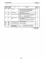
About This Manuals
The following manuals are available
Please
order desired manuals
regarding this product,
using this chart.
I Related Manuals I
Manual name
Control & Communication-Link System Master-Local module type AJ61 BT1 I/Al SJ61 BTI 1
User’s Manual
Manual No.
(Typs code)
IB (NA) 66721
(13J872)
This manual describes the system configuration, performance specifications, functions,
handling, wiring and troubleshooting of theAJ61BT11 andAlSJ61BT11
(sold separately).
-
AJ61QBT1 I/AlSJ61QBT11
USER’S MANUAL
Control& Communication Link System Master/Local Module
IB (NA) 66722
(13J873)
This manual describes the system configuration, performance specifications, functions,
handling, wiring and troubleshooting of theAJ61QBT11 andAlSJ61QBT11
(sold separately).
Positioning module software package type SW1 IVD-AD75P Operating Manual
This manual describes how to create data (such as parameters and positioning data) and the
operations to transfer data to the module, monitor positioning and conduct tests using the
above software package (supplied with each software package product).
.-
IB (NA) 66714
(13J915)
Introduction
Thank you for purchasing
the Mitsubishi
Before using the equipment,
performance
please
of MELSEC-A-series
MELSEC-A-series.
read this manual carefully to develop full familiarity
you have purchased,
with the functions and
so as to ensure correct use.
Please fotward a copy of this manual to the end user.
Table of Contents
1.
1-1 to 1-22
Overview
I
1.1 Features ............................................................................................................................................................
1.2
1-2
Purpose of Positioning .................................................................................................................................... .. 1-4
1.3
Types of Positioning ..........................................................................................................................................
1.4
Overview of Positioning Control ........................................................................................................................ 1-7
1.5
1.5
U
1.4.1
Data setting required for positioning control ........................................................................................ 1-7
1.4.2
Positioning control methods ................................................................................................................ 1-8
1.4.3
Specification of positioning address .................................................................................................... 1-9
1.4.4
Operation pattern ................................m............................................................................................... 1.10
1.4.5
Block positioning control ...................................................................................................................... 1-11
1.4.6
Overview of acceleration/deceleration
1.4.7
Ovewiew of start ................................................................................................................................. 1.13
1.4.8
Overview of restati .............................................................................................................................. 1-14
1.4.9
Overview of home position return ........................................................................................................ 1-15
processing .............................................................................. 1-12
Overview of Communication .......................................................m..................................................................... 1-17
1.5.1
Cyclic transmimion ..............................................................................................................................l.l8
1.5.2
Transient transmission ........................................................................................................................ I-lg
1.6
General Procedure before Operation ................................................................................................................ 1-20
1.7
Abbreviations, General Names and Terms Used in this Manual ...................................................................... 1-21
1.8
Parts Supplied with the Module ........................................................................................................................ 1-22
2.
System Configuration
2.1
Sptem
2.2
2.4
Applicable System ..................................................................................................................................... ....... 2-2
List of Equipment .............................................................................................................................................. 2-3
Precautions when Using a Stepping Motor ....................................................................................................... 2.4
3.
Specification
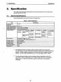
3.1
General Specifications ......................................................................................................................................3.
2.3
3.2
3.3
3.4
2-1 to 2-5
3-1 to 3-28
1
3.2.1
Performance Specifications .........................................................................................,...,,,,.,,.,..,,,,,,.,,.,,,,
,,, ,,, ,. 3-2
Performance specifications .................................................................................................................3- 2
3.2.2
Specifications for 1/0 interface with external devices .......................................................................... 3-4
1/0 Signals for the Master Module .................................................................................................................... 3-12
3.3.1
List of 1/0 signals .................................................................................................................................3.l2
3.3.2
Functions of 1/0 signals ....................................................................................................................... 3-16
Remote Register ..................................................................................................................................... .......... 3-23
3.4.1
Remote register assignment ................................................................................................................ 3-23
3.4.2
Positioning statt number
........".............................................................................................................3.24
3.4.3
Override .................................................................................................................................... ........... 3-24
3.4.4
New present value ............................................................................................................................... 3-24
3.4.5
I
Configuration when Using the D75P2 ..................................................................................................2. 1
New speed value ................................................................................................................................. 3-25
I
‘u
3.4.6
JOG speed ..........................................................................................................................................3.25
3.4.7
Present feed value ..............................................................................................................................3.25
3.4.8
3.4.10
Feed speed ......................................................................................................................................... 3-26
Valid M code ........................................................................................................................................ 3-26
Axis error number ................................................................................................................................ 3-26
3.4.11
Axis warning number ........................................................................................................................... 3-26
3.4.9
3.5
MIS operation status ...........................................................................................................................3.26
Transmission Delay Time ................................................................................................................................. 3-27
4.
Function List
4.1
Function hst ......................................................................................................................................................~
5.
Home Position Return Function
5.1
What is the Home Position Return Function?. ...................................................................................................5
5.2
Types of Home Position Return ........................................................................................................................5- I
5.3
Precautions when Performing Home Position Return .......................................................................................5- 2
Home Position Return Start Method ................................................................................................................. 5-3
Start flow ....................................................................................................................................... ...... 5-3
5.4.1
3.4.12
c
5.4
5.5
4-1 to 4-2
1
1
5-1 to 5-31
I
1
5.4.2
Mechanical home position return start ................................................................................................5- 4
5.4.3
High-speed home position return stati ................................................................................................5- 4
5.4.4
High-speed mechanical home position return .....................................................................................5- 6
5.4.5
Data-set type home position return .....................................................................................................5- 7
Home Position Return Method ..........................................................................................................................5- 8
Near-point dog type home position return ........................................................................................... 5-6
5.5.1
5.5.2
Count-type 1) home position return (using the zero signal) ................................................................5.l0
5.5.3
Count-type 2) home position return (not using the zero signal) .......................................................... 5-12
5.5.4
Stopper stop-type 1) home position return (using time out of dwell time) ...........................................5-14
5.5.5
Stopper stop-type 2) home position return (using the zero signal upon hitting the stopper) ............... 5-18
5.5.6
Stopper stop-type 3) home position return (no near-point dog method) .............................................. 5-21
Data-set type home position return ..................................................................................................... 5-23
5.5.7
5.6
5.7
Home Position Return Retry Function .............................................................................................................. 5-24
5.6.1
What is the home position return retwfunction? .................................................................................5.24
5.6.2
Actions of the home position return retvfunction ...............................................................................5.24
5.6.3
Home position return methods and execution of the home position return retry function ...................5-26
5.6.4
Conditions when executing the home position return retry function .................................................... 5-26
5.6.5
Dwell time setting at home position return retry ..................................................................................5.27
Home Position Shift Function ............................................................................................................................ 5-28
5.7.1
5.7.2
5.8
5.9
What is the home position shfifunction? ............................................................................................$28
Specifying speed during home position shifi .......................................................................................5.3O
Home Position Return Request Flag OFF Request .......................................................................................... 5-31
Combining Home Position Return with Other Functions ...................................................................................5.3l
5.9.1
5.9.2
Home position return start after home position return operation stops ................................................ 5-31
Changing the speed during home position return ............................................................................... 5-31
4
Positioning
6.1
Function
6-1 to 6-64
Positioning Control Methods .............................................................................................................................6- 1
6.1.1
6.1.2
6.1,3
6.1.4
Control method ....................................................................................................................................6- 2
Interpolation control ............................................................................................................................. 6-3
Single-axis linear control .....................................................................................................................6- 5
Dual-axis linear interpolation control. ..................................................................................................6- 7
6.1.5
Fixed-dimension feed control ..............................................................................................................6.ll
6.1.6
6.1.7
Circular interpolation control with a specified auxiliary point ..............................................................- 6-15
Circular interpolation control with the specified center point ...............................................................6.2O
6.1.8
Speed control (forward rotation/reverse rotation) ................................................................................ 6-25
!
6.1.9
Speed/position switch control (forward rotation/reverse rotation) .......................................................6.27
JUMP instruction .................................................................................................................................6.3l
Operation Pattern of Positioning Control .......................................................................................................... 6-33
6.2.1
Individual positioning control (operation pattern: 00) ........................................................................... 6-33
6.1.10
6.2
6.2.2
Continuous positioning control (operation pattern 01) ........................................................................ 6.34
6.2.3
6.3
Continuous locus control (operation pattern: 11) ................................................................................ 6-35
Starting Positioning Control .............................................................................................................................. 6-43
6.3.1
Overview of start ................................................................................................................................. 6-43
6.3.2
Start method .................................................................................................................................... .... 6-49
6.3.3
Special start .........................................................................................................................................6.5l
6.3.4
6.4
Setting the bias speed at start ............................................................................................................. 6-54
Lontrol
Stopof -Posmomng
... .
. ............................................................................................................................... 6-55
6.4.1
Stop command and stop factors.. ........................................................................................................ 6-55
6.4.2
6.4.3
Stop processing and priority ................................................................................................................ 6-58
Stop processing during deceleration ................................................................................................... 6-60
6.4.4
Stop processing during interpolation operation ................................................................................... 6-60
Continuous-operation interrupt function .............................................................................................. 6-61
Restating Positioning Control .......................................................................................................................... 6-63
6.4.5
6.5
6.5.1
6.5.2
What is restart after a stop? ................................................................................................................ 6-63
Specifying the restart after a stop ........................................................................................................ 6-63
6.5.3
Precautions .........................................................................................................................................6.64
Other Functions
7.1
7.1.1
Speed change by the override function ............................................................................................... 7-13
7.2.3
Acceleration/deceleration-time
7.7
7.9
Software stroke limit function .............................................................................................................. 7-22
u-
Confirmation and Change of Present Value ..................................................................................................... 7-27
7.5.1
7.8
.
Torque change function ....................................................................................................................... 7-19
Stroke Limit Function ................................................................................................................................... ..... 7-20
7.4.1
Stroke limit function via external input ................................................................................................. 7-20
7.5.2
7.6
setting for speed change ....................................................................7.l5
Torque Limit Function .......................................................................................................................................7.l7
7.3.1
Torque limit function ............................................................................................................................7.l7
7.4.2
7.5
Speed change via the remote register for speed change ....................................................................7- 9
7.2.2
7.3.2
7.4
JOG operation ..................................................................................................................................... 7-1
Manual pulse generator operation ....................................................................................................... 7-7
Speed Change Function during the Positioning Operation ............................................................................... 7-9
7.2.1
7.3
I
Manual Operation .................................................................................................................................... ......... 7-1
7.1.2
7.2
7-1 to 7-68
w
Confirmation of present value ............................................................................................................. 7-27
Present value change .......................................................................................................................... 7-29
Electronic Gear ..................................................................................................................................... ............ 7-32
Backlash Compensation Function .................................................................................................................... 7-34
M-code Function ............................................................................................................................................... 7-35
Acceleration/Deceleration Processing .............................................................................................................. 7-38
7.9.1
Relationship among speed limit value, JOG speed limit value, acceleration time,
deceleration time and rapid stop deceleration time ............................................................................. 7-39
7.9.2
Acceleration/deceleration processing .................................................................................................. 7-40
7.10 Skip Function ................................................................................................................................................. ... 7-41
7.11 Step Function .................................................................................................................................... ................ 7-43
7.12 Command In-position Function ......................................................................................................................... 7-47
7.13 Teaching Function ..................................................................................................................................... ....... 7-49
Handling when the Control Unit is in “Degree” ................................................................................................. 7-53
7.14.1 Address of present feed value and machine feed value ..................................................................... 7-53
7.14
7.14.2
7.14.3
Setting valicfhnvalid of software stroke limit ......................................................................................... 7-53
Positioning control ............................................................................................................................... 7-55
7.15 Setting the Stepping Motor Mode ..................................................................................................................... 7-57
.
7.16 Present Feed Value Clear Function at the Start of Speed Control and Speed/Position Switch Control ........... 7-61
7.17 Write to the Flesh Memory ................................................................................................................................ 7-62
7.18 Pulse Output Logic Switch ................................................................................................................................7.63
7.19 Parameter Initialization Function .......................................................................................................................7.M
7.20 When Constructing the Absolute Position Detection System Using the D75P2 ............................................... 7-65
7.21 Sewo ON/OFF ..................................................................................................................................................7.67
18.
8-1 to 8-37
Buffer Memory
8.1
Outline of Buffer Memory ..................................................................................................................................8-
8.2
Classification of Buffer Memo~ Areas ..............................................................................................................8- 1
8.3
Reading and Writing Data in the Buffer Memo~ ...............................................................................................8- 3
8.4
Configuration of Btier
8.5
Parameter Area .................................................................................................................................................8-
.,n
8.6
8.7
8.8
8.9
I
1
Memo~ ........................................................................................................................8- 4
5
8.5.1
Basic parameter 1 ...............................................................................................................................8- 5
8.5.2
Basic parameter2
8.5.3
Extended parameter 1 .........................................................................................................................8- 7
...............................................................................................................................8- 5
8.5.4
Extended parameter 2 .........................................................................................................................8- 9
8.5.5
Home position return basic parameter ...............................................................................................8.1 O
8.5.6
Home position return extended parameters ........................................................................................8.ll
Monitor Area .....................................................................................................................................................8.l2
8.6.1
System monitor area ...........................................................................................................................8.l2
8.6.2
Axis monitor area ................................................................................................................................8.l9
Control Data Area .............................................................................................................................................8.23
8.7.1
System-control data area ....................................................................................................................8.23
8.7.2
Axis-control data area .........................................................................................................................8.26
Positioning Data Area .......................................................................................................................................8.28
Positioning Start Information Area ....................................................................................................................8.3O
8.9.1
Positioning start data area ...................................................................................................................8.3l
8.9.2
Special start data area ........................................................................................................................8.32
8.9.3
Condition data area .............................................................................................................................8.33
8.10 Indirect Specification Area ................................................................................................................................8.35
8.11 PC CPU Memo~ Area ......................................................................................................................................8.36
8.12 Area for Block Transfer .....................................................................................................................................8.37
j 9.
Setup
9-1 to 9-25
9.1
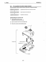
Name of Each Part ............................................................................................................................................9-
1
9.2
Handling Precautions ........................................................................................................................................9-
3
9.3
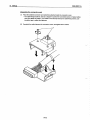
Module Installation ............................................................................................................................................95
9.3.1
DIN rail installation (removal) ..............................................................................................................9- 6
9.3.2
9.4
9.5
9.6
9.7
Installation to (removal from) the panel ...............................................................................................9- 8
Wking/Connections... ........................................................................................................................................9- 9
9.4.1
Pin connection to the drive module connector ....................................................................................9.1 I
9.4.2
Connector connection (removal) .........................................................................................................9.l4
9.4.3
Twisted cable connection ....................................................................................................................9.l5
Setting the Main Module ...................................................................................................................................9.l7
9.5.1
Setting the station number of the main module ...................................................................................9.l8
9.5.2
Setting the transmission speed of the main module ............................................................................9.l9
Display Viewpoint ..............................o...............................................................................................................9.2O
9.6.1
17-segment/corresponding-axis
9.6.2
Message descriptions for operation monitor 2 ....................................................................................9.2l
display LEDs ....................................................................................9.2O
9.6.3
Signal names of 1/0 information 'n" .....................................................................................................9.2l
9.6.4
Descriptions of other messages ..........................................................................................................9.2l
System Test ......................................................................................................................................................9.22
I
.
10.1 Basic Parameters .............................................................................................................................................. 10- 1
10.1.1 Unit setting ...................................................................................................................................... .... 10-4
10.1.2 Travel increment per pulse .................................................................................................................. 10-4
10.1.3
Pulse output mode .............................................................................................................................. 10-6
10.1.4
Rotation direction seting ..................................................................................................................... 10-8
Speed limit value ................................................................................................................................. 10-8
10.1.5
10.1.6
10.1.7
10.1.8
10.1.9
Acceleration time O.............................................................................................................................. IO- 9
Deceleration time 0 ............................................................................................................................. 10-9
Bias speed at stati ............................................................................................................................... 10-9
Stepping motor mode selection ........................................................................................................... 10-9
10.2 Extended Parameters ....................................................................................................................................... 10-11
10.2.1 Backlash compensation ...................................................................................................................... 10-14
10.2.2
Software stroke limit ............................"............................................................................................... 10-14
10.2.3
Software stroke limit selection ............................................................................................................. 10-14
10.2.4
Software stroke limit validfinvalid setiing ............................................................................................. 10-14
10.2.5
10.2.6
Command in-position range ................................................................................................................ 10-15
Torque limit...................................................................................................................................... .... 10-15
10.2.7
M-code ON signal output timing .......................................................................................................... 10-15
10.2.8
Speed switch type ............................................................................................................................... 10-15
10.2.9
Interpolation speed specification ......................................................................................................... 10-16
~
.
10.2.10 Present feed value during speed control ............................................................................................. 10-17
10.2.11 Manual pulse-generator selection ....................................................................................................... 10-17
10.2.12 Selection for pulse output Iogicto drive module .................................................................................. 10-17
10.2.13 Acceleration/deceleration time setting size selection .......................................................................... 10-18
10.2.14 Acceleration time 1 to 3 ....................................................................................................................... 10-18
10.2.15 Deceleration time 1 to 3 ...................................................................................................................... 10-18
10.2.16 JOG speed limit value ......................................................................................................................... 10-18
10.2.17 JOG operation acceleratiorddeceleration
time selection ..................................................................... 1O-18
10.2.18 JOG operation deceleration time selection ......................................................................................... 10-19
10.2.19 Acceleration/deceleration
processing selection .................................................................................. 10-19
10.2.20 S-curve ratio ....................................... ............................................................................................ .... 10-19
10.2.21 Rapid-stop deceleration time. .............................................................................................................. 10-20
10.2.22 Rapid-stop selection (Stop groups 1 to 3) ........................................................................................... 10-20
10.2.23 Positioning-complete signal output time .............................................................................................. 10-20
10.2.24 Allowable circular-interpolation error range ......................................................................................... 10-21
10.2.25 External start function selection .......................................................................................................... 10-21
10.< Home Position Return Basic Parameter
.......................................................................................................... 10-22
10.3.1
Home position return method .............................................................................................................. 10-22
10.3.2
Home position return direction ............................................................................................................lo.22
10.3.3
Home position address ........................................................................................................................ 10-23
10.3.4
10.3.5
Home position return speed ................................................................................................................ 10-23
Creep speed ........................................................................................................................................ 10-24
10.3.6
Home position return retw ................................................................................................................... 10-25
10.4 Home Position Return Extended Paramete~
................................................................................................... 1O-26
10.4.1
Home position return dwell time .......................................................................................................... 10-26
10.4.2
Travel increment setting after near-point dog ON ............................................................................... 10-26
10.4.3
Home position return acceleration time selection ................................................................................ 10-26
10.4.4
Home position return deceleration time selection ............................................................................... 10-26
10.4.5
Home position shift amount ................................................................................................................. 10-26
10.4.6
Home position return torque limit value ............................................................................................... 1O-28
10.4.7
Home position shift speed specification .............................................................................................. 10.28
L’
10.4.8
11.
Dwell time at home position return ret~ .............................................................................................. IO-28
Batting Positioning
Data
11-1 to 11-13
I
11.1 What is Positioning Data? ................................................................................................................................. 11- 1
11.2 Positioning Data ...................................................... ................................................................................ ........... 11- 1
11.2.1
Operation pattern ................................................................................................................................ 11-4
11.2.2
Control method .................................................................................................................................... 11-4
11.2.3
Acceleration time number .................................................................................................................... 11- 4
11.2,4
Deceleration time number ................................................................................................................... 11- 4
11.2.5
Positioning addresshravel increment .................................................................................................. 11- 5
11.2.6
Circular address .................................................................................................................................. 11- 6
11.2.7
Command speed ................................................................................................................................. 11-6
11.2.8
11.2.9
Dwell time ....................................--------------.......................................................................................... 11-7
Jump destination data number ............................................................................................................ 11- 7
I1.2.1o
M code .................................................................................................................................................
11- 7
11.2.11 Condition data number ........................................................................................................................ 11- 7
O
11.3 positioning Start information ............................................................................................................................. 11- 8
11.3. I
Positioning start data ........................................................................................................................... 11- 8
11.3.2
Special start data ................................................................................................................................. 11- 9
11.4 Condition Data ....................................................................................................................................... ........... 11-11
12.
11.4.1
Condition identifier ............................................................................................................................... 11-11
11.4.2
Address ..............................................................................................................................................-
11.4.3
Parameter 1 ......................................................................................................................................... 11-13
11.4.4
Parameter 2 ......................................................................................................................................... 11-13
11.4.5
Parameter 1 and parameter 2 settings for simultaneous stati ............................................................. 11-13
Building a System
11-13
‘ 12-1 to 12-38
I
12.1 Overview ...................................................................................................................................................... ..... 12- 1
12.2 Master Station Setiings ..................................................................................................................................... 12-2
12.3 D75P2 Setiings ................................................................................................................................................. 12-3
12.4 Concept of Transient Transmission .................................................................................................................. 12-4
12.4.1
12.4.2
,-
Read/write of the buffer memov ......................................................................................................... 12- 4
Transient transmission ........................................................................................................................ 12- 6
12.4.3
Control datalsend data setting procedures ......................................................................................... 12- 7
12.5 Programming ......................................................................................................................................... ........... 12-16
12.5.1
Programming procedure ...................................................................................................................... 12-16
13.
12.5.2
Notes on creating programs ................................................................................................................ 12-17
12.5.3
Creating programs ............................................................................................................................... 12-18
12.5.4
Parameter setting/data link start program ........................................................................................... 12-22
12.5.5
Communication/positioning programs ................................................................................................. 12-25
Troubleshooting
13-1 to 13-12
I
13.1 Troubleshooting Flow when “ERRmLED of Master Station is Flickering ........................................................... 13- 1
13.2 ErroreiWamings of D75P2 ................................................................................................................................ 13-3
13.2.1
Errors ....................................................................................................................................... ............ 13-3
13.2.2
Warnings .............................................................................................................................................
13.2.3
13-4
Resetting the error ............................................................................................................................... 13-5
13.2.4
invalid operations ................................................................................................................................ 13- 5
13.3 Corrective Actions for Errora ...............................................................................!...... ....................................... 13-6
13.4 Corrective Actions for Wamlngs ....................................................................................................................... la-lo
13.5 Error Start History ...................................................................................................................................... ....... 13-12
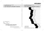
Appendix
Appendix 1
A-1 tO A-42
External Dimensions Diagram .............................................................................................................. A- I
I
Appendix 2
Format Sheet ........................................................................................................................................A.
2
Appendix 2.1
Positioning module operation diagram .........................................................................A. 2
Appendix 2.2
Parameters, home position return data ........................................................................A. 3
Appendix 2.3
Appendix 3
Appendix 4
Positioning data (data number to ) ........................................................................... A- 7
Positioning Data Number and Buffer Memory Address Conversion Table .......................................... A- 8
Connection Examples of D75P2 and Servo Amplifier ..........................................................................A.lO
Connection example of D75P2 and MR-H ❑ A
(differential driver (open collector), negative logic) ......................................................A.lO
Appendix 4.1
Appendix 5
Appendix 4.2
Connection example of D75P2 and MR-J •l A
(differential driver (open collector), negative logic) .......................................................A.ll
Appendix 4.3
Connection example of D75P2 and MR-J2- •l A
(differential driver (open’collector), negative logic) ......................................................A.l2
Appendix 4,4
Connection example of D75P2 and MR-C El A
(differential driver (open collector), negative logic) ...................................................... A-13
Connection Example with Servo Amplifier by Yasukawa .....................................................................A.l4
Connection example of D75P2 and CACR (R series)
(differential driver, negative iogic) ................................................................................A.l4
Appendix 5.1
Appendix 6
Connection Examples with Stepping Motors by Oriental .....................................................................A.l5
Appendix 6.1
Connection example of D75P2 and VEXTAUDX2107
(differential driver, positive logic) ................................................................................. A-15
Appendix 6.2
Connection example of D75P2 and VEXTA UPD
(differential driver, positive logic) .................................................................................A.I6
Appendix 6.3
Connection example of D75P2 and VEXTA-FX
(differential driver, positive logic) .................................................................................A.l7
Appendix 6.4
-
Connection example of D75P2 and VEXTAUDX2107
(Opt?n collector method, negative logic) .......................................................................A.l8
Appendix 7
Appendix 6.5
Connection example of D75P2 and VEXTA UPD
(open collector method, negative 10giC) . . . . . . . . . . . . . . . . . . . . . . . . . . . . . . . . . . . . . . . . . . . . . . . . . . . . . . . . . . . . . . . . . . . . . ..A.l9
Appendix 6.6
Connection example of D75P2 and VEXTA-FX
(Open collector method, negative logic) ....................................................................... A.20
Connection Example with Servo Amplifier by Toei Electric ..... .............................................................A.2l
Appendix 7.1
Appendix 8
Connection Example with Servo Amplifier by Matsushita Electric Industries ...................................... A-22
Appendix 8.1
Appendix 9
Connection example of D75P2 and VLASE 01 OP
(differential driver, positive logic) .................................................................................A.2l
Connection example of D75P2 and MSD5A3A1 X
(differential driver, positive logic) .................................................................................A.22
Station Numbers - Remote 1/0 and Remote Register Conversion Table ............................................ A-23
Appendix 10 MELSEC Glossary of Positioning Terms ..........~ ..................................................................................A.24
\_/
Function Explanation
Volume
Pan 1 desoribes the basic topics relating to the AJ65BT-D75P-S3 positioning
module product, as well as the information the user should know when operating the
product.
<Overview of contents>
Chapter 1
Overview
Chapter 2
System Configuration
Chapter 3
Specification
Chapter 4
Function List
Chapter 5
Home Position Return Function
Chapter 6
Positioning Function
Chapter 7
Other Functions
Chapter 8
Buffer Memory
1.
1.
MELSEC-A
Overview
Overview
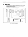
.
This users manual describes the specifications, handling and programming method for the AJ65BTD75P2-S3 positioning module (hereinafter referred to as the D75P2), which can be used as an
intelligent device station for the CC-Link system.
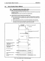
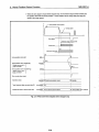
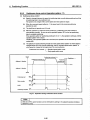
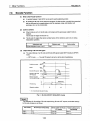
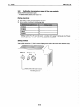
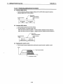
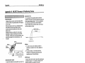
An overview of the D75P2’s positioning control is shown in Figure 1.1.
Mastermodule
D75P2
Drive module
Servo motor
Forward
pulse
Communication
~
●
Error value
Set data
WA
Speed
command
Sewo
-
~
b
Reverse
pulse
Converter
Counter
A
-J
Interface
T
Feedback pulse
n
T
Speed (V)
. A7PHP
. A7HGP
. PC9800
series
. DOSN
personal
computer
. AD75TU
r speed
.
Ftg. 1.1 Overview of positioning
1-1
control
1.
Overview
1.1
MELSEC-A
Features
The features of the D75P2 are listed below.
(1)
Compatible
wfth distributed
systems
The D75P2 can be placed near a distributedly allocated servo amplifier or stepping motor.
(2)
Easily adaptable to an absolute-position detection system
(a)
By connecting a servo system that supports absolute positions, the D75P2 can be used with
an absolute-position detection system.
(b)
Once the location of the home position has been determined, the D75P2 can return to the
address prior to power-up using the absolute-position restoration function.
(c)
With the absolute-position detection system, the location of the home position can be
determined by means of the data-set-type home position return.
Therefore, wiring to items such as a near-point dog is required.
,-.
(3)
Control via mechanical system input is possible
With external inputs such as external start, stop and speed/position switch, the positioning control
can be performed without using a sequence program.
(4)
Various positioning
(a)
control functions are available
Various functions required of a positioning system are included, such as positioning control
to any position, fixed-dimension feed control and uniform speed control.
An overview of positioning control functions is provided in Section 1.4.
●
●
A maximum of 600 data items per axis can be set for positioning data, including the
positioning address, control method, operation pattern, etc..
Linear control (two-axis simultaneous execution is allowed) can be performed for the
positioning of each axis: independent positioning using one positioning data item, or
continuous positioning via the continuous execution of multiple data items.
.
Linear interpolation control with two axes, as well as circular interpolation control, can be
done for the positioning of multiple axes: independent positioning using one positioning
data item, or continuous positioning via the continuous execution of multiple data items.
(b)
The control methods specified by positioning data include the position control, speed control
and speecflposition switch control.
(c)
Depending upon the operation pattern set by the user using positioning data, continuous
positioning can be performed for multiple axes or each axis using multiple positioning data
items.
Continuous positioning can also be performed for multiple blocks, each of which consisting
of multiple positioning data items,
(d)
The home position return control has been extended.
.
Seven types of home position return methods are available: the near-point dog method
(one type), stopper stop method (three types), count method (two types) and data-set
method (one type).
(However, the data-set method is available only when using an absolute-position
system.)
●
The home position return retry function is now available in order to realize positioning
control from any position relative to the home position of a machine.
(e) Two acceleration/deceleration methods are available: the automatic trapezoid
. acceleratiorddeceleration and S-curve accelerationldeceleration. The user can seleot from
the automatic trapezoid acceleration/deceleration or S-curve acceleration/deceleration.
1-2
MELSEC-A
1. Overview
(5)
(6)
Faster pulse output and longer distance to the drive module
(a)
The D75P2 is equipped with pulse-output interfaces for a differential driver and an open
collector.
(b)
By connecting to the differential driver, higher speed and longer distance can be achieved.
●
When connecting to a deferential driver
:400 kpps, 10 m (32.8 ft.) maximum.
●
When connecting to an open collector
:200 kpps, 2 m (6.6 ft.) maximum.
Easy maintenance
The D75P2 has achieved improved maintainability, as in the following:
(a)
Various data such as positioning data and parameters are stored internally in the flash
memory of the D75P2.
Therefore, data can be retained without a battery.
(b)
Error display and the status of mechanical system input and zero input can be checked on
the 17-segment monitor.
(c)
Errors are subdivided in order to improve first-time diagnostics.
(d)
Confirmation of the contents of errors and warnings is done easier than the way it has been
conventionally done, since 16 items each of history data, such as errors and warnings, can
be retained.
d
L
1-3
1.
Ovetview
1.2
MELSEC-A
Purpose of Positioning
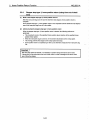
The positioning refers to moving a movable object (processed materials, tools, etc.) at a fixed speed
and stopping it accurately at the intended position.
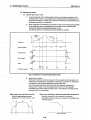
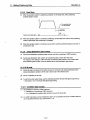
Typical usage examples are shown below.
(1)
Fixed-dimension
feed
Feed a sheet for a fixed dimension
J J cut
and cut it.
-
I
d
Feed motor
Fig. 1.2 Fixed-dimension
(2)
fead
Tapping
To perform thread chasing to a
fixed depth for processed material,
repeat the following steps:
Thread chasing motor
m
1) Fast forward
2) Process feed (thread chasing)
k)-
Fast forward
3) Fast rewind
Process feed
Fast rewind
Fig. 1.3 Tapping
(3)
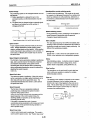
Steel-plate
drilling (X-Y table movement)
Drill a hole at the fixed position
+
O
using two motors (one motor each
for vertical and horizontal).
No.2
Y3
!I
Y2
,Y4
@
No.1
o+
No.3
@
YI
1
xl
I
x2
x3
Zero
*
*
Horizontal feed motor
Fig. 1.4 Steel plate drilling
x4
J
No.4
1.
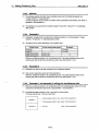
MELSEC-A
Ovefview
1.3
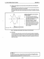
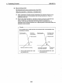
Types of Positioning
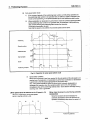
Each of the two axes can be used independently for positioning, or the two axes can be used for the
positioning of orthogonal axes.
The following methods as shown in the figures are available when positioning from address number 1
to number 2.
(1) Individual operation
This is a method by which each of the vertical and horizontal directions is positioned individually.
First, positioning is performed in the horizontal direction X, then in the vertical direction Y.
No.2
__l
Y
No.1
x
(2)
Simultaneous
oparation
This is a method that designates one of the two motors to perform positioning in the X direction
and the other in the Y direction, driving them simultaneously to reach the intended position.
Since each of the acceleratiorddeceleration time, speed and travel distances for the two motors is
independent, this operation moves along a curve.
No .2
,.
Linear interpolation
“J
operation
This is a method that operates two motors simultaneously to move along a straight diagonal line.
To move along a straight line, calculation is performed via the positioning module equipped with
an interpolation function, and the resultant pulse is distributed to the two motors for control,
because the acceleration/deceleration times and speeds of the two motors generally vary.
No.2
/4
I
:Y
No.1
. . . . . . ..-
x
1-5
J
1.
Ovefview
MELSEC-A
(4)
Circular interpolation
operation
This is a method that operates two motors simultaneously to execute the interpolation operation
for the circular locus.
To move along a circular line, calculation is performed for the positioning module equipped with a
circular interpolation function that controls the acceleratiorddeceleration times and speeds of the
two motors, and the resultant pulse is distributed to the two motors for control.
:r
1
1
: Auxiliary
point
---
,.’
Y!
/“
:’
:
No.1
‘,+
I
1
t
‘--j0.2
s
Y!
\ ,
#
,
t
P
/-/”
No.1
‘+’
No.2
-—-
Center point
L-------------------------------x
k-----------------------------
x
C!rcular interpolation by apacifying
an auxiliary point
F’--
1-6
Circular interpolation by specifying
the center point
MELSEC-A
1. Overview
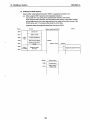
Overview of Positioning Control
1.4
This section describes the data that needs to be set for positioning, along with the types of positioning
controls and operation patterns available.
1.4.1
Data setting required for positioning
..
control
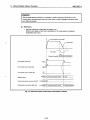
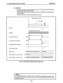
In order to perform positioning using the D75P2, several data items listed below must be set.
Data for which setting is required
I
Parametew for positioning
I
T
Basic parameter 1
Basic parameter 2
Extendad parameter 1
Extended parameter 2
These are set accordingto the system configurationand
mechanical equipment.
i
t
Parameters for
home position return
Basic parameter
Data for positioning
Positioningdata
u
Extended parameter
1-
Positioningstart
information
}
}
This sets how to controland operate a machine.
This is set when a special etart such ae block etart,
simultaneous start, repeated start or starI by condition
testing is performed.
Positioningstart data
}
This sets which positioningdata to start with,
and whether to end or continua positioning
for the nexl block.
t
Special start data
t-
L
Conditiondata
}
3
This sets the start type.
Thie sets the conditionsfor special positioning.
L/’
1-7
1.
Overview
MELSEC-A
1.4.2
Positioning
control
methods
The following positioning functions are available for the D75P2, and they are controlled by control
methods “’of 1) through 8). Use positioning data to set the control method.
*1) to 6): Control of ‘positioning” locus and OPWtXiOfI
7) to 8): Control of “positionin~ data
Linear positioning function
This performs positioning along a straight locus from
.................. the current stop position toward the specified position.
1) Linear control of single-axis
2) Linear interpolation control
of dual-axes
}
Fixed-dimension feed-positioning function
3) Fixed-dimension feed control .................. This performs positioning for the specified travel along
a straight locus from the current stop position.
n
I Circular positioning function I
.-”.
4) Circular interpolation control .................... This performs positioning along a circular locus from
the current stop position towards the specified position.
Speed-control positioning function
5) Speed control .......................................... This moves at the specified speed from the current stop
position toward the specified position.
(The operation continues until a stop command is
input.)
Speed/position switch positioning function
6) Speed/position switch control =......oc..c.- This moves at the specified speed from the current stop
position toward the specified position, and performs
positioning for the specified travel from the moment a
speedlposition switch signal is input.
Present-value change function
7) Present value change ............................. This changes the present feed value to the specified
7---
value.
JUMP function
8) JUMP instruction .................................... This jumps the control point to the specified positioning
data number while in the continuous locus control
(operation pattern: 02). (Specification of unconditional
or execution condition is made.)
●1: See Section 6.1 for details on control methods.
1-8
1.
MELSEC-A
Overview
1.4.3
Specification
of positioning
address
For positioning control, there are two methods used to designate a position.
(1)
Absolute method
This method performs positioning by specifyhg the position relative to home position (absolute
address). This address is used as the positioning address (the starting point can be positioned at
any location).
1
t
Addrees
100
aI
~
~
:
,
~
I
Home position
(reference point)
t
,
4
Address 150
.
:
J
I
I
100
Point A
Starting point
Endpoint
k
Address 100
w
,
-
●
Address
300
t,
Address 150
●
,
o
Address :
150
:
,
,,
I
Address
100
,
300
Point C
150
Point B
Within the stroke limit range
4
B
Fig. 1.5 Positioning
(2)
Increment
by
method
bsolute method
1
This method performs positioning by specifying th direction and increment of travel using the
currently stopped position as the statitng point.
—’
+100
Travel increment +100
~ Travel incr ment
1
L,’
Home position
(reference point)
100
Point A
150
Point B
300
Point C
Within the stroke limit ranbe
Fig. 1.6 Positioning
1-9
by i~rement
method
.
1.
Overview
MELSEC-A
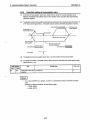
1.4.4
Operation
pattern
The following types of operation patterns are available.
●
●
Individual positioning
(ends positioning)
Individual positioning control (operation pattern: 00)
Continuous positioning
Continuous positioning control (operation pattern: 01)
(continues positioning)
-.,
L
(1)
Individual positioning
Continuous locus control (operation pattern: 11)
control (operation pattern = 00: ends positioning)
The operation is completed with positioning for the specified positioning data alone. The
positioning completion of this operation pattern is also used as the operation pattern for the last
positioning data of continuous positioning and continuous-locus positioning.
(2)
Continuous
positioning
control (operation pattern = 01: continues
positioning)
The operation stops temporarily upon the completion of positioning for the specified positioning
data, then continues with the next positioning data number.
This is specified when performing positioning in which the direction changes because of multiple
positioning data items having consecutive positioning data numbers.
(3)
Continuous
locus control (operation
pattern = 11: continues positioning)
After executing positioning using the specified positioning data, the operation changes its speed
to that of the next positioning data number and continues positioning.
This is specified when continuously executing multiple positioning data items having consecutive
positioning data numbers at a specified speed.
1-1o
1. Overview
MELSEC-A
1.4.5
Block positioning
control
Block positioning is a control that continuously executes the positioning of specified blocks. One block
is equivalent to a series of positioning data up to the completion of positioning (operation pattern = 00)
by individual or continuous positioning control.
A maximum of 50 blocks per axis can be specified.
Using a one-time start command from the PC CPU or external, complex positioning control can be
performed.
The block positioning control can be performed by specifying the positioning start number and
positioning statl information in the buffer memory.
Speed
Positioning continued (01)
Owen time
Positioning completed (00)
.
Address (+) direction
Positioning completed (00)
,
,,
.
~Time
t
Pos~tioni~g continued (11)
0,
,,
,,.
,,
,,
,,
,,
Address (-) direction
v
Speed
#
,
!
,,
: ON
,,:
One block
.:.
,,
,,
,,
:
:
!l(
tioning continued~(ll)
,
,
,
One bloc~
,
,
,
,
~
,
,
One block
$
B1
,
Positioning start
OFF
Start completed
OFF
BUSY
OFF
Positioning completed
1
,
‘
,,
,
i
‘.-/’
.
.
.
1-11
1. Ovefview
MELSEC-A
1.4.6
Overview ofacceleration/decelerationprocessing
Acceleration/deceleration processing for the positioning operation, manual pulse-generator operation,
home position return operation and JOG operation is performed using the user-specified method,
acceleration time and deceleration time.
(1)
Acceleration/deceleration
method
There are two types of acceleration and deceleration processing: the automatic trapezoid
accelerationldeceleration method and the S-curve accelerationldeceleration method. An
extended parameter is used to set which method is used.
The specified acceleratiorddeceleration method is applied to all accelerations and decelerations
when starting and completing the positioning operation, home position return operation and JOG
operation, as well as when changing the speed.
1)
Automatic trapezoid acceleration/deceleration
method
This method accelerates and decelerates in a linear fashion based on the speed limit value
and user-specified acceleration time/deceleration time.
Speed
b2)
DLstance
S-curve acceleration/deceleration
method
This method reduces the load on the motor when starting and stopping.
This method gradually accelerates or decelerates based on the user-specified acceleration
time and deceleration time, S-curve ratio (1 ?4. to 100 7.) and speed limit value.
Speed
----
~ O@tance
(2)
Acceleration
(a)
time, deceleration
time, rapid-stop deceleration
time
Four types each of the acceleration time and deceleration time for positioning control can be
set using basic parameter 2 and extended parameter 2.
Also, the acceleration time and deceleration time can be selected from 1 to 65535 ms or 1 to
8388608 ms using the acceleration/deceleration time setting size selection in extended
parameter 1.
(b)
●
Acceleration time ..... The time elapses before the speed of O reaches the limit value.
●
Deceleration time ---- The time elapses before the speed at the limit value reaches O.
The rapid-stop deceleration time (1 to 65535 ms or 1 to 8388608 ms) is set using the
acceleration/deceleration time setting size selection of extended parameter 1.
EiEl
The selection of 1 to 65535 ms or 1 to 8388608 ms for the acceleration time, deceleration time and
rapid-stop deceleration time is set for each axis.
1-12
MELSEC-A
1. Ovewiew
1.4.7
Overview of start
Wkh the positioning control, operation is started in the following flow after the necessary parameters
and data have been set.
.
\d’
.x
1-13
1.
Overview
MELSEC-A
1.4.8
Overview of restart
If the operation stops due to the generation of a stop factor during the positioning operation, the
positioning of stopped positioning data can be performed to the endpoint using the restart command.
(1) When the remote i/O generates a restart command
1)
If the axis operation is in the stop state, positioning from the stopped position to the end of
the stopped positioning data is performed regardless of the absolute method or increment
method used.
2)
If the axis operation is in other than the stop state, a restart disabled warning (warning code
104) occurs and the restart command is ignored.
[For the increment method]
When the travel increment along axis 1 is 600 and that along axis 2 is 300
Axis 2
Axis 2
Stop position by a stop factor
Stop position by a stop factor
------400 - -----Starting
pointaddress
..”
t
200 ----00
I
~
100 -1
I
100
(2)
300
When the positioning
-z-~ Specified position
#-a
,
Rest art
,
—
1
1
,
1
1
1
D Axis 1
700
400 - ----------200 -
---------
&
,
Stop position
I after restart
Qoperation
1
I
300
“,on
~ restart
I
- Axis 1
700
start signal or externai start signal is turned on
if the axis operation is in standby or the stop state, positioning is performed from the head of the
positioning start data regardless of the absoiute method or increment method used (as with
normai positioning).
[For the increment method]
When the travei increment aiong axis 1 is 600 and that aiong axis 2 is 300
Axis 2
Stop position by a stop
--- ‘----<-~
400 - -----~.
Starting
pointeddress -.. -”
1
200 “- --,~
100 -I
100
300
Axis 2
Stop position by a stop factor
-------------5or) -------
factor
Specified position
1
Positioning start
I
—
1
200 - -----1
1
1
1
b Axis 1
700
1-14
Stop position
I after start
l/
I Operation
,?
~when starting
: Starting point address,
, positioning
* Axis 1
300
900
1.
MELSEC-A
Overview
.
1.4.9
Overview of home position return
The home position return is to confirm mechanical home position at power-on or other times.
The following seven types of home position returns are available.
(1)
Near-point dog type (one type)
This type stops by a zero signal after the near-point dog switches from on to off.
(2)
Stopper type (three types)
Stopper (1) (due to the elapse of the dwell timer)
(a)
The home position return of this type completes when the dwell time has elapsed after being
decelerated by the near-point dog switching on and stopped by a stopper.
Stopper (2) (due to a zero signal when coming in contact with a stopper)
(b)
The home position return of this type is completed by a zero signal after decelerated by
near-point dog on and stopped by a stopper.
(c)
Stopper (3) (no near-point dog method)
The home position return of this type is completed by a zero signal after it has moved at the
creep speed and stopped by a stopper.
-
\
(3)
Count type (two types)
Count type (1) (using the zero signal)
(a)
The home position return of this type is stopped by the zero signal once after moving for the
specified travel increment once the near-point dog has been turned on.
(b)
,.
Count type (2) (without using the zero signal)
The home position return of this type is stopped by moving for the specified increment of
travel after the near-point dog has been turned on.
wear-point dog type]
Current position
t
t
,
*
Speed
4
,
t,
II
,
_rw
(1)1
Speed
A
,
,
,
\
,
,
t
,
,
,
8
t,
II
$1
,,
,,
,,
,s
,,
w Time
,,
*Time
u
{,
[count type (1)]
,
~
Speed
T~avel increm$mt
-
~
,
*
,
,
I
I
d
Home positionreturn
start signal
Near-point dog signal
Zero signal
,
t
0
t
8
,
,
t
~
~
ii
to
It
,,
11
,,
,,
,,
,,
1
,
0
i,
F Time
,
1.
Overview
MELSEC-A
(4)
Data-set type (one type)
The home position return of this type sets the home position address to the present value during
the home position return execution.
This can be used for the absolute-position system.
x----
EEl
1) Home position return can also be performed via the home position return retry function using the
high and low limit switches.
2) After the home position has been determined by the home position return operation, the
positioning operation can be used until the machine’s feed value reaches the home position
address, without using the home position detection signal.
(This equates to positioning to the home position position.)
1-16
1,
MELSEC-A
Overview
1.5
Overview of Communication
Communication between the D75P2 and a master module uses two types of transmission formats:
cyclic transmission and transient transmission.
An overview of communication using the D75P2 is shown in Figure 1.7.
.
D75P2
I
Pc CPU
Master station
TO instruction (write)
7
Cyclic transmission
FROM instruction (read) !
Buffer memory
Tranaient transmission
w,
.
Fig. 1.7 Overview of communication
.
-.
-.
“.
..
\2
.
..
..
1-17
1.
Overview
MELSEC-A
1.5.1
Cyclic transmission
The following explains the cyclic transmission between the D75P2 and master module.
D75P2
Master station
Pc CPU
Buffer memorv
-E
D J-J-u
2)
—
FROM
1)
Remote input
(RX)
1
3)
—
Link scan
4)
Remote output
(RY)
II
5
Remote register
(RWW)
K= J-El
i=
-c
8)
—
FROM
1
Remote output
(RY)
Link scan
b
i=
5)
—
Remote input
(Rx)
7)
Remote register
(RWr)
Link scan
J
Remote
register
(RWr)
II
I
Fig. 1.8 Cyclic transmission
(1)
(2)
Remote input (RX)
1)
The information in the remote input (RX) of the D75P2 is stored in the buffer memory of the
master station during each link scan.
2)
The input information stored in the master module is captured by the PC CPU using a FROM
instruction.
Remote output (RY)
3)
The information in the remote output (RY) of the D75P2 is written to the buffer memory of
the master station by a TO instruction.
4)
The output information stored in the master module is transmitted to the D75P2 during each
link scan.
.
(3)
(4)
Remote register (RWW)
5)
The information in the remote register (RWW) of the D75P2 is written to the buffer memory of
the master station by a TO instruction.
6)
The transmission data information stored in the master module is transmitted to the D75P2
during each link scan.
Remote register (RWr)
7)
The information in the remote register (RWr) of the D75P2 is stored in the buffer memory of
the master station during each link scan.
8)
The reception data information stored in the master module is captured by the PC CPU
using a FROM instruction during each link scan.
1-18
1.
MELSEC-A
Overview
1.5.2
Transient
transmission
The following explains the transient transmission between the D75P2 and master module.
Pc CPU
D75P2
Master station
f
b
1
Buffer memory
3)
1)
--c
Readrkwite
+
1
I
b
Transient transmission
2)
B
-,
Transient
transmission area
.
Buffer memory
4)
5)
1
4
Transient transmission
II
.
Fig. 1.9 Transient transmission
1)
2)
3)
4)
Sets data in the send buffer on the master module.
Sets an intelligent device station access request signal.
The transient data is transmitted from the master module to the D75P2.
A response is returned from the D75P2 to the master module.
5)
The intelligent device station access complete signal is turned on.
..
..
1-19
1.
1.6
Overview
MELSEC-A
General Procedure before ODeration
The following shows the general flowcharl for positioning using the D75P2.
Q
Start
+----..--------------------
~------ --------------------
Install the AD75P onto a peripheral device
~- ------------------------c-------------------------i .-.-----------------------
r --------------------------
_
J
_
Set parameters and data
k. . . . - . - . . . . . . . . . . . . . . . . . . . . . . . . . . . . . . . . . . . . . . . . . . . . . 4
1
+---------------------------
r --------------------------
: Write the setting data to the D75P2 using the peripheral device :
,---- ----.----------------k-------------------------J
/-+ --------
r -------------------------,
~--------------------------
------------------
Run an operation test
-----------------.-,------
.
J
o
Start
operation
-----------
-,
~ . . See the AD75P operating manual
I. _ . ---------!
1-20
1.
1.7
,.
MELSEC-A
Overview
Abbreviations,
General Names and Terms Used in this Manual
I Abbreviations,
Description
genarsl
names, terms
D75P2
An abbreviation for the AJ65BT-D75P2-S3
CC-Link
An abbreviation for the Control& Communication Link system
Master station
The station that controls remote stefions, 100alstations and intelligent device stations
on the CC-Link system.
Remote 1/0 station
The remote station that handles bit data only.
(AJ65BTBIZ-130, AJ65BTCCI-UO)
Local station
A station having a CPU and the ability to communicate with the master and other local
Intelligent device station
A slave station on the CC-Link system that can perform transient transmission, such
as the D75P2.
Master module
The general name for AJ61 QBTI 1, Al 3J61 QBT, AJ61 BTI 1 andAlSJ61BT11
they are used as master stations.
Cyclic transmission
A transmission method that periockelly updates the remote 1/0 and contents of remot(
registers.
Transient transmission
positioningmodule.
when
.
‘4
A function that updates data with respect to the specified station when an access is
requestadfroma PC CPU.
Perf~heraldevice
I The general name for the A7PHP, A7HGP, PC9801 and DOS/V Dersonal computers
.
that can execute the AD75P given below.
(This is listed separately from the peripheral devices for GPP, as listed below.)
Drive module
(Servo amplifier)
An abbreviation for the pulse-input-compatible drive module (servo amplifier).
Manual pulse generator
An abbreviation for the manual pulse generator (supplied by the user).
Data link system
An abbreviation for the MELSECNET (N) or MELSECNET/B data link system.
Network system
An abbreviation for the MELSECNET/1 O network system.
AD75P
The general name for the software packages SWCIRX-AD75P, SWDNX-AD75P and
SWCHVD-AD75P.
(U indicates a numeral greater than 1, which corresponds to the software package
function.)
w
An abbreviation for hardware.
IF
An abbreviation for interface.
Peripheral device for GPP
The general name for the A7PHP, A6GPP, PC9801 and DOS/V personal computers
and others to which the software package for the GPP function for creating sequence
programs, etc., is installed.
Sfw
I An abbreviation for software package.
17-segment LED
The 17-segment indicator mounted in the upper area of the D75P2.
RX
Remote input
RY
Remote output
RWW
Remote register (read area)
RWr
Remote resister (write area)
1-21
d
1.
Ovefview
1.8
MELSEC-A
Parts Supplied with the Module
When unpacking, check that all of the parts listed below are included. Also, check whether there is
any damage to the parts after unpacking.
Quantity
Description
Main module (AJ65BT-D75P2)
1
External wiring connector (10136-3oOOVE)
2
Connector cover (10336-52FO-OO8)
2
..
r---
1-22
2. System Configuration
2.
MELSEC-A
System Configuration
This chapter describes the system configuration using the D75P2.
2.1
System Configuration
when Using the D75P2
The Figure below shows the system configuration when using the D75P2.
A maximum of 16 D75P2 modules can be connected to a single master station.
I
3
!=====
“ See-[
IIII
(l).
AD75TU
Manual pulss gsnerator
I!!aJ
Manual pulse
generator
--
‘ Seal Important (2),
-.
Servo amplifier
Fig. 2.1 System configuration
Important
Serv; amplifier
when using the D75P2
I
(1) The software packages liSted below are required in order to use the D75P2.
●
For DOSA/ personal computec SW1 IVD-AD75P or later
(2) USe SOftWareversion D or later for the DA75TU.
2-1
2. System Configuration
2.2
MELSEC-A
Applicable System
This section describes the CC-Link system master module that can be used with the D75P2 and PC
CPUS that can be used with CC-Link dedicated instructions.
(1)
Master modules that can be used with the D75P2
To use the D75P2, use a moduie with the foliowing symbol (“9707S” and later) inscribed in the
date column of the rated plate.
I
PROGRAMMABLE
CONTROLLER
I
DATE 9707 B
6-1-
I
9707
B.
B
TT
Manufactured
Manufactured datel
Function version
(2)
:
m
date
CC
I
Function version
PC CPUS that can be used with CC-Link dedicated instructions
The PC CPU models listed below can be used with the CC-Link dedicated instructions:
AI SHCPU
Al SJHCPU
A2SHCPU
Q2ACPU (function version B or later)
Q2ACPU-S1
(function version B or later)
Q3ACPU (function version B or later)
Q4ACPU (function version B or later)
Q2ASCPU (function version B or later)
Q2ASCPU-S1
(function version B or iater)
Q2ASHCPU (function version B or iater)
Q2ASHCPU-S1
(function version B or later)
2-2
MELSEC-A
2. System Configuration
2.3
List of Equipment
Table 2.1 lists the products that can be used for a positioning system using the D75P2.
Table 2.1 List of equipment
Product name
Contents
Model name
‘positioning
module
AJ65BT-D75P2-S3
;oftware package for AD75
SW1 IVD-AD75P or later
Software package for DOSIV personal computer
‘Iasma handy graphic
Programmer
A7PHP-SET
. A7PHP main module
---,—— —- ——— —- —-— —— -— --A7HGP-SET
{andy graphic programmer
-—.
SW{:: RX-DOS :
●
SW; I j SRXV-GPPA: GPP functionbootfloppydisk for A
series
●
SWOS-USER :
User floppy disk (2HD)
● AC30R4 :
RS-422 oabla, 3 m (9.8 ft.) in length
_____________________
● A7PHP main module
. SW ~1~HX-DOS:
●
.—— ——— ——— ——— ——— ————————————
PC9800 series
‘eripheral device for AD75P
DOS/V personal
computer
Basic software package
●
Basic software package
SW [ j; HX-GPPA: GPP function boot floppy disk for A
series
●
SWOS-USER :
User floppy disk (2HD)
●
AC30R4 :
RS-422 oable, 3 m (9.8 ft.) in length
. Shoulder
———
——— strap
— — __________________
(Supplied by the user)
Refer to the AD75P operating manual for details.
‘eaohing module
AD75TU Ver. D or later
This sets parameters and positioningdata, monitors and
conducts tests for AD75P2.
W.-422 cable
AC30R4
——--———————
AC1OOR4
———————————
AC300R4
Length: 3 m (9.8 ft.)
—__________
Length: 10 m (32.8 ft.)
___________
;onvereion oable
Al SD75-CO1 H
D75P2 and A7PHP or A7HGP.
Length 30 m (98.4 ft.)
Length 10 cm (3.94 in.) The cable for connecting the
Al SD75-CO1 HA
>onnectioncable (converter)
The oable for connecting the
ACIIj R4 cable and D75P.
The RS-232C cable that mnnects the AD75 and the
PC9801 or DOSN personal computer, and the
RS232C/RS422 converter (supplied by the user).
Refer to the appendix for details.
)rive module
(Supplied by the user)
Aanual pulse generator
(Supplied by the user)
Recommended: MR-HDPOI (manufactured by Mitsubishi
Electric)
>onnetiton
%able*
Absolute-position AD75C20SH
detection
The cable for the connection between the D75P2 and
servo amplifier (M R-H-A)
function
compatible
The cable for the connection between the D75P2 and
servo amplifier (M R-J2-A)
AD75C20SJ2
Absolute-position AD75C20SJ
deteotion
The cable for the connection between the D75P2 and
servo amplifier (M R-J-A)
function
noncompatible
The cable for the connection between the D75P2 and
servo amplifier (MR-C-A)
AD75C20SC
>onn@ron cable
The cable for connecting the D75P2 to the mechanical
system input signal or manual pulse generator (supplied b
the user).
Refer to the manual for details on the connection device.
IJE!!!d
*: For the connector cover on the D75P2
2-3
side, use the one supplied with the product.
2. System Configuration
2.4
MELSEC-A
Precautions when Using a Stepping Motor
This section describes the precautions when using a stepping motor.
(1)
When setting the stepping motor mode
(a)
When using a stepping motor with the D75P2, it is necessary to set the stepping motor
mode.
(b)
When the stepping motor mode is set, certain restrictions apply to items such as the control
method and positioning address.
If the stepping motor mode is not set, the stepping motor cannot be controlled normally.
Use the module after verifying the restrictions that apply to the stepping motor mode in
Section 7,15.
(2)
Use of bias speed at start
While the stepping motor is used, the motor rotation can be started smoothly by selecting the
stepping motor mode and setting the bias speed at start.
(3)
The use of S-curve acceleratiotideceleration
is not allowed
While the stepping motor is used, S-curve acceleration/deceleration
(4)
Circular interpolation
cannot be performed.
control is not allowed
While the stepping motor is used, circular interpolation control cannot be performed.
,---
2-4
2-5
MELSEC-A
3. Specification
3.
Specification
Ttis chapter explains the general specifications, performance specifications and 1/0 interface with
external devices for the D75P2.
3.1
GeneraI Specifications
General specifications for the D75P2 are shown in the table below
Table 3.1 General specification
Item
Specification
Ambient operating
temperature
o to 55 “c
Ambient storage temperature
-20 to 75 “c
Ambient operating humidity
10 to 90 %RH, Non-condensing
Ambwnt storage humidity
10 to 90 %RH, Non-condensing
Vibration resistance
Conformingto
JIS B 3501,
IEC 1131-2
Acceleration
Under intermittent 10t057Hz
vibration
57 to 150 Hz
Under continuous 10t057Hz
vibration
57 to 150 Hz
—
9.S m/s2{1G)
—
4.9 m/s2{0.5G}
Amplitude
0.075 mm
(0.003 in.)
—
0.03S mm
(0.001 in.)
—
No. OfSWe9pS
10 times each in
x, Y, z
directions
(for 80 min.)
Conformingto JIS B3501, IEC 1131-2
(147 m/s2(15G}, 3 times in each of 3 directions X Y Z)
Shock resistance
Operating ambience
No corrosive gases
Operating elevation
2000 m (6562 ft.) max.
Installation location
Control panel
Over voltage category’1
m-,,...,-- ,-. .-, ..-.
romnon level ‘z
II max.
A...
1z max.
●1: This indicates the section of the power supply to which the equipment is assumed to be
connected between the public electrical power distribution network and the machinery within the
premises. Category II applies to equipment for which electrical power is supplied from fixed
facilities. The surge voltage withstand level for up to the rated voltage of 300 V is 2500 V.
This index indicates the degree to which conductive material is generated in terms of the
environment in which the equipment is used. Pollution level 2 is when only non-conductive
pollution occurs. A temporary conductivity caused by condensation must be expected
occasionally.
3-1
MELSEC-A
3. Specification
Performance
3.2
Specifications
Performance specifications for the D75P2 are shown in the table below:
3.2.1
Performance
specifications
Table 3.2 Performance
..=,,,
Harm
specifications
umberof controlaxes
lterpolation
function
ontrolmethod
(1)
Snedfication
_r___
._
.____
I
2 axes
Dual-axislinearinterpolation,
dual-axiscircularinterpolation~1)
PTP (Pointto Point)control,locuscontrol(linearand circularsettingspossible),SpeSd COntrOl,
speed/position switch control
ontrol unit
mm, inch, degree, pulse
ositioningdata
600 data (positioning-data numbe~ 1 to 600)/sxis setting possible
eriphersl deviceahoftware
DOSN personaloomputer/SWlIVD-AD75Por later~2)
ackeges
esching module
AD75TU (software version D or later)
,acku
Parameters and positioningdata are stored in the flash memory (no battery)
: Increment system/absolute system
PTP control
Speed/position switch control : Increment system
: Increment system/absolute system
Locus control
‘positioning Positioning method
Positioning range (*3)
Absolute system
● -2147.46364.8 to 214746364.7 (Vm)/-l 3421772.8 to 13421772.7 (pm)
● -21474.63646
to 21474.83647 (inches)/-l 342.17726 to 1342.17727 (inches)
O to 359.99999 (degrees)/O to 359.99999 (degrees)
6 –21 47483648 to 2147483647 (pulses)/-l 34217726 to 134217727 (pUISeS)
●
Increment system
● -2147483r346
to 214746364.7
● -2 I 474.63646 to 21474.83647
. -21474.&Mi46 to 21474.83647
. -21 47463648to2147463647
(~)1-1 3421772.6 to 13421772.7 (Vm)
(inches)/-l 342.17726 to 1342.17727 (inches)
(degrees)/-l 342.17728 to 1342.17727 (degrees)
(pulses)/-l 34217728 to 134217727 (pulses)
Speed/position switch control
. Oto214746364.7 (urn)/o to 13421772.7 (Vm)
● Oto21474.83647
(inches)/O to 1342.17727 (inches)
● O to 21474.83647 (degrees)/O to 1342.17727 (degrees)
. 0 to 2 1474S3647 (pulses)/O to 134217727 (pulses)
Speed command ~3)
. 0.01 to 6000000.00 (mrn/min.)/O.01 to 375000.00 (mm/min.)
0.001 to 600000.000 (inches/min.)/O.001 to 37500.000 (inches/min.)
● 0.001 to 600000.000 (degrees/min.)/O.001 to 37500.000 (degrees/min.)
● 1 to 1000000 (pulse/sac.)/l to 62500 (pulse/sec.)
Acceleration/deoelera - Automatic trapezoid accelerationldeceleration, automatic S-cuwe acceleratiotidecaleretion ~4)
tion processing
Acceleration/decelera - Switching between 1 to 65535 (ins) and 1 to 6368608 (ins) is possible
tion time
4 patterns of acceleration and deceleration time setting are possible
Switching between 1 to 65535 (ins) and 1 to 6368806 (ins) is possible
Rapid-stop
(same range as accelerationldeceleration time)
dsasleration time
●
Start time
hmpensstion
+ome position return method
!bsolute-poeitiondetection funtilo n
IOG operation funtilon
danual pulse-generator operation
unction
d-oode outputfuntiion
Errordisplay
.- .. .
20 ma or leas (except link ssan time)
Electronic gear or backlash compensation available
~
Compatible with absolute-position detetilon systems using MR-H and MR-J2
Available
Available
Available (either WITH mode or AFTER mode can be selected)
17-segment display
.-. d:--,----- -1, -= 4:--, -..
*1 Circular interpolation osnnot be used while the stepping motor is usad.
“2
DOSN is a registered trademark of IBM Japan.
*3
Indiostes the setting rangas of the “standard mode/stepping motor mode.”
~4 While the stepping motor is in use, automatic S-curve accslerationldeceleration oennot be used.
‘5
Valid only with an absolute-position detetiion system.
3-2
3. Specification
MELSEC-A
Table 3.2 Performance
specifications
Item
SpeclflcfrtIon
CC-Link station typa
Number of occupied stations
4 stations (128 points each for R)URY, 16 points each for RWr/RWw)
Exlemal power supply (V)
24 DC (20.4 to 26.4 DC)
Applicable conductor size (mm’)
Module installation screws (mm)
0.75 to 2.00
M4 x 0.7 x 16 or above
Installation with DIN rail ia also possible
Applicable DIN rails
Intelligent device station
TH35-7.5Fe, TH35-7.5AI, TH35-15Fe (complies with JIS-C2B12)
Applicable sokfariess terminal
RAV1.25 to 3.5, RAV2 to 3.5
24 V DC internal current
consumption (A)
0.30
Noise reaistanca
Dielectric withstand voltage
,-.
(2)
I
I Noise voltage 500 Vp-p, noise width 1 w
(based on a noise simulator with noise frequency of 25 to 60 Hz)
Power supplykommunicafion system batch - external l/O batch, 500 V AC for 1 minute
Insulation resistance
Power supplykommunicetion system batch - external 1/0 batch, 10 MQ or more baaed on a 500 V DC
insulation resistance tester
External dimensions (mm fin.])
63.5 (2.5) (H)
0.50 (1.1)
Weight (kg [lb.])
X
170 (6.7) (W) X 80 (3.1 ) (D)
3-3
MELSEC-A
3., Specification
3.2.2
Specifications
for 1/0 interface with external devices
This seotion explains the 1/0 interface of the D75P2 with respect to external devices.
(1)
Electrical specifications
of the D75P2
The table below shows the electrical specifications for D75P2 1/0 signals with respect to external
devices:
(a)
Input specifications
.
.
3-4
3. Specification
MELSEC-A
(b)
Output specifications
Ratedload
voltage
Signal name
Maximum load
currentl
rush currant
Rangeof load
voltage used
Leek
currant
duringoff
Maximum
VOitS~
drop
duringon
Response
time
‘ulse output
Am26LS31-equivalent differential driver/opan collector
CW/PLfLSE/phaae A)
CW/CCW type, PULSE/SIGN type and phase A/B typa are seleoted using the D75P2 and drive moduk
parameters.
The relationshir)sbetwean the pulse output mode set by the parameter and the pulse output based on
“msitive Icwichwfrativelogic selection” are shown below:
aekotion
CCW/SIGfVphaee B)
Negativelogic
Positive logic
Mode
‘ulse sign
Forwardrotation
Reverse rotation
Forwardrotation
Reverserotation
Cw
Ccw
l--i--
i PULSE
I SIGN
Low
High
Low
J
High
In the csse of open collector, the rise/fall time and duty ratio are as shown by the figure below
-----
.-
—-
-- - —————---
.— ---
. —-——.
- ---.——-——————
lto24VDC
4.75 to 30 V DC
50 mAlone poinfl
200 mA 10msor
less
0.5 V DC (TYP)
0.1 mA or
leas
—
%ror counter clear (CLEAR)
ito24VDC
4.25 to 30 V DC
0.1 Alone poinf/
0.4 A10msor
leas
1 V DC (TYP)
2.5 V DC (MAX)
0,1 mA or
leas
2 ms or
less
(resistive
load)
3ewo on
ito24VDC
4.75 to 30 V DC
0.1 A/one pointi
0.4 A10msor
less
1 V DC (TVP)
2.5 V DC (MAX)
0.1 m A or
leas
2 ms or
leas
(resistive
load)
4BS datatransmission
mode
4BSdata request
PUISe fk@/fa}l df?le (Unit tr, tf: @; rju~
~0)
2
200
————
100
—--------200
100
--——10
20
200
---100
-——10
50
. . ..-
. . -----
when the ambient temperature is normal temperature
4.75
tr (rice)
tf (tall)
Duty tr (rise)
tf (fall)
30
0.06
.-—---33
0.07
————
.——
46
0.08
2.04
----3.49
———-
3 (9.6)
1 (3.3)
3 (9.8)
Duty tr (riea)
tf (fall)
Duty tr (rtse)
tf (fall)
Duty
%%)
10
5
D75p2
1 (3.3)
Cablefangth(m [ft.])
Pulse
the
26.4
Load voltage (V)
Load
currant
(mA)
in
1.70
0.04
—--————
3.00
0.06 — -—-——
_——
3.20
0.07
0.06
---—0.07
----—
0.07
------
0.07
0.07
----——
0.07
200
-——----100
0.0s
.----—
0.06
----
10
0.09
1.10
.- --——
1.24
--—1.20
39
.-—
43
.-—
49
0.42
46
!----0.40
G
.- —-—— .——
0.40
50
0.28
——
-0.27
---—
0.27
48
.-—
46
--50
8.80
.-
27
29
-—
48
1.63
33
0.07
-———
.——
————
2.50
36
0.08
—-——
.—— ——— .——
2.70
49
0.08
0.06
‘0-’7
—— -- 0.06
0.09
--—0.13
--—0.09
0.72
---0.74
---—
0.04
---0.06
—---
0.63
--—0.64
----
0.04
0.64
0.04
———0.05
———.
0.05
0.06
—-——
0.0%
—---
0.79
43
-—
47
,-—
50
0.37
——-—
0.37
——-—
47
——
48
-—
0.06
--——
0.06
———-
0.37
3-5
50
0.26
46
———.—0.26
46
———— .-—
0.30
50
0.22
.- —--0.24
----
47
.-—
---50
0.24
50
0.06
0.08
0.04
1.08
43
---.—— —— -———
1.28
47
0.04
---,------1.30
49
0.06
0.20
47
—— .-—
0.22 - --- 49
_——
,--—
0.22
50
0.04
——-—
0.06
—-—0.06
0.06--—
0.00
——-—
0.06
0.10
——-—
0.12
———0.12
38
.——
42
--49
0.92
--——
0.44
----
--- 47
4:
0.44
50
0.22
49 .
---.-—
0.Z6
50
.————— .-—
50
0.24
0.18
—--—
0.20
-— --
--- 50
--- 51
0.20
50
MELSEC-A
3. Specification
(2)
Specifications
Specifications
for t/O interface
with external
devices
for 1/0 interface of the D75P2 with respect to external devices are shown in the
table below
(a)
Pin
No.
Pin layout
w
(External device)
cold
e
(External device)
ABS transmission data ready complete 18)
TLC
Drive module
33
Common (ABS IN) 19)
COM
+
—
32
Common (ABS OUT) 20)
COM
—
Drive module
31
ABS request 21 )
ABSR
+
Drive module
30
ABS transfer mode 22)
ABSM
+
Drive module
29
Servo on 23)
SON
+
Drive module
PULSER B-
6
Manual pulse generator
34
‘an”a’
‘“’se generator
Manualpulsegenerator}
Common3)
Zero signalcommon5)
Zero signal(+5 V) 6)
PULSERACOM
PGOCOM
PGO(5 V)
+
e
+
+
Manualpulsegenerator
Drivemodule
Drivemodule
Drivemodule
23
Error counter clear common 4)
CLEAR COM
e
Drive module
22
Pulse sign (differential -)
PULSE R-
-)
Drive module
21
Pulse output (dtierential -) }
Pulse sign common
PULSE F-
+
Drive module
PULSE COM
e
Drive module
(Open collector)
19
1
.
2)
Drive module
26
25
24
20
[
Connection deatinatiorr
COM
common
1)
Common }
27
18
Signal direction
AD75 - external
Signal name *
3=
35
28
=
Layout of connector signals
The signal layout of the connector for connecting external devices to the D75P2 (for one
axis) is shown below:
(Axis 1 and 2 use the same signal layout for connecting external devices.)
7)
_/,
‘
s,
19
Puiee output common
}
(Opsn collector)
PULSE COM
++
Drive module
18
ABS data bit 1
ZSP
+
Drive module
17
ABS data bit O}
DO1
+
Drive module
16
External start 9)
STRT
+
(Errternal device)
15
Speecf/poeition switch signal 10)
CHG
+
(External device)
14
Stop signal 11)
STOP
+
(External device)
13
Low limit 12)
RLS
+-
Limit switch
12
High limit 13)
FLS
+
Limit switch
11
Near-point signal 14)
DOG
+
Near-point dog
10
Manual pulse generator
PULSE B+
+
Manual pulse generator
9
Manual pulse generator }
PULSE A+
+
Manual pulse generator
8
In-position 15)
INPS
+
Drive module
7
Drive module ready 16)
READY
+
Drive mcdule
6
Zero signal (+24 V) 6)
PGO (24 V)
+-
Drive module
5
Error counter clear 17)
CLEAR
+
Drive module
4
Pulse sign (differential +)
pulse R+
+
Drive module
3
Pulse output (differential +) }
pulse F+
+
Drive module
-+
Drive module
24)
2)
2
Pulcmeign (nrxm ealloetar)
1
Pulse output (open collector)}
7)
PUL!2G R
8)
PULSE F
Dive
me&le
“ 1) to 24) beside signal names are numbers corresponding to the explanations in “(b) Description of
connector signals.”
3-6
L/
‘
MELSEC-A
3. Specification
(b)
Description of connector signals
The description of each signal for the connector for connecting external devices to the
D75P2 (for one axis) is explained below
1)
Common --- (Pin numbers 36, 35)
●
2)
A common for the near-point signal, high/low limit, stop signal, control switch signal,
and external start.
Manual pulse generator (phase B -), manual pulse generator (phase A -)
--- (Pin numbers 28, 27)
Manual pulse generator (phase B +), manual pulse generator (phase A +)
--- (pin numbers 10, 9)
●
Inputs the phase A/B pulse signal of the manual pulse generator and rotary
encoder.
●
When phase A is ahead of phase B, the positioning address increases.
●
When phase B is ahead of phase A, the positioning address decreases.
[when increasing]
[when decreasing]
‘haseAwTPhase B
Positioninga
address
3)
7)
+2
..........
Positioning E
address
–1
-2
..........
A common for the drive module ready and in-position.
A common for the error counter clear.
Zero signal common --- (Pin number 25)
●
6)
+1
Error counter clear common --- (Pin number 23)
●
5)
Phase B
Common --- (Pin number 26)
●
4)
Phase A
A common for the zero signal (+5 V) and zero signal (+24 V).
Zero signal (+5 V), zero signal (+24 V) --- (Pin numbers 24,6)
●
Inputs the home position signal at the time of home position return.
Generally, the home position grid signal of a pulse encoder is used.
●
This signal is also used when the home position return method is “stopper stop” and
the home position return complete is input externally.
●
The zero point is detected at fall.
Pulse sign, pulse output (differential -) --- (Pin numbers 22,21)
Pulse sign, pulse output (differential +) --- (Pin numbers 4, 3)
●
The pulse and pulse sign for positioning are output to the drive module that
corresponds to the differential driver.
8)
Pulse sign common, pulse output common (open collector) --- (Pin numbers 20, 19)
Pulse sign, pulse output (open collector) --- (Pin numbers 2, 1)
.
9)
The pulse and pulse sign for positioning are output to the drive module that
corresponds to the open collector.
External start --- (Pin number 16)
●
Used as an input signal for external positioning start, speed change request or skip
request.
●
The selection of external start function in extended parameter 2 determines in which
function the external start is used.
3-7
MELSEC-A
3. Specification
10) Speed/position switch signal --- (Pin number 15)
●
Input control switch signals during speed/position switch control.
11) Stop signal --- (Pin number 14)
12)
●
Input when positioning is stopped.
●
When this signal turns on, the D75P2 stops the positioning currently executed and
turns off the start signal.
After that, the D75P2 will not start operating even if this signal is switched from on
to off.
Low limit --- (Pin number 13)
●
Input from the limit switch provided at the low limit of stroke.
●
When this signal turns off, positioning stops.
●
Become the low limit of search for the near-point signal when automatic home
position return is enabled.
13)
14)
15)
High limit --- (Pin number 12)
●
Input from the limit switch provided at the high limit of stroke.
●
When this signal turns off, positioning stops.
●
Become the high limit of search for the near-point signal when automatic home
position return is enabled.
Near-point signal --- (Pin number 11)
●
Used for near-point dog detection during home position return.
.
Detects the change in near-point dog from off+. on at rise.
●
Detects the change in near-point dog from on + off at fall.
In-position --- (Pin number 8)
●
16)
-\/’
The in-position signal from the drive module is input.
Drive module ready --- (Pin number 7)
Turn on when the drive module is normal and is in a feed-pulse acknowledge
enable state.
The D75P2 checks the drive module ready signal and outputs a home position
return request if it is not in a ready status.
This signal is turned off when the drive module becomes malfunction, for example,
when an error occurs in the control power supply of the drive module.
If this signal is turned off during positioning, positioning stops. Operation does not
start even if the signal is turned on again.
When this signal turns off, the home position return complete signal also turns off.
3-8
\_/
‘
3. Specification
MELSEC-A
17)
Error counter clear --- (Pin number 5)
●
Turns on after pulse output stops when home position return is performed using the
stopper stop method 1) or 2).
(Example) Home position return using the stopper stop method 2)
Speed
I
1
,
,
I
1
,
1
Near-point dog
‘erode’ec’ion
signs’
v
4
; 10ms
+
I
After feed-pulse output stops
●
The error counter clear is output for approximately 10 ms.
●
As for the drive module, use one that can reset the standing pulse amount for the
internal error counter when the D75P2 turns this signal on.
18) ABS transmission data ready complete --- (Pin number 34)
●
This signal indicates that preparation of transmission data is complete during the
ABS transfer mode.
19) Common (ABS IN) --- (Pin number 33)
s A common for the ABS data bit O, ABS data bit 1 and ABS transmission data ready
complete.
20)
Common (ABS OUT) --- (Pin number 32)
.
21)
ABS request --- (Pin number 31 )
●
22)
A common for the servo ON, ABS transfer mode and ABS request.
This is the signal for requesting ABS data in the ABS transfer mode.
ABS transfer mode --- (Pin number 30)
●
Changes the mode to ABS transfer.
●
While this is on, the “ABS data bit O [DO1],” “ABS data bit 1 [ZSP~ and “ABS
transmission data ready complete NLCl” signals become valid.
23)
Servo ON --- (Pin number 29)
●
This signal turns on power to the servo base circuit and changes
operation
24)
the status to
enable.
ABS data bit O, bit 1 --- (Pin numbers 17, 18)
●
ABS data transferred to the D75P2 from the servo during the ABS operation mode.
bit O indicates the lower bit, while bit 1 indicates the upper bit.
3-9
MELSEC-A
3. Specification
(c)
Internal circuits
The internal circuits of interface for connecting external devices to the D75P2 are shown by
the schematic diagrams below.
O : Whing required, A: Wire as necessary
Uo
Pin No.
External wiring
Signal name
Internal circuit
Description
otioff statua
Wbfng
rsquirad
lsesifi-
External D75p2
ation
Input
-0
When the high
limitswitch
is not usad
-. . . . ..,
4
(
11
Near-peint
signal
DOG
. Thesignalfornear-point
detection 4—*
duringhomepositionreturn.
-ct-o-
ON
12
High limit LS
FLS
.
The signal for the limitewttch
providedat the high limitof etroke.
*
ON
.
Also ueed in the home peaition
returnretry function.
4=*
The signal for tha limitswitch
providedat the low limitof elroks.
*
.
Neo used in the home pesition
returnretry funtiton.
4=*
.
The signal to Sop positioning
externally.
When atoppingpositioning,tum
this signal on for 4 ms or longer.
4—+
Once thie signal is turned on,
switching~ bsck to offdoes not
resume operation.
~
OFF
(Stop)
The signal that switchesspeed
controlto positioncontrolduring
speed/positionswitchcontrol.
-5-+
OFF
~
ON
4—*
OFF
-O-W
ON
I
When the low
limitswitch
is not used
--------&I
Low limit LS
13
RLS
t
Stop signal
14
STOP
●
●
(*
4
.
15
Speedl
(i-o
CHG
●
position
(
switchsignal
Extemel start STRT
16
()+
4
~.----
-
+
)
35
-l}
*.. ,
.
The signal that executes external
positioningeiart, spaed change
and SKIP request.
. To make estemal Sart valid, turn
thk signal on for 4 ms or longer.
●
Set which functionto usa tia an
estendsd parameter.
Common
COM
.
Inputvoltage 24 V DC.
Manual
pULSER A+
●
The terminal for mnnasting the
OFF
A
o
OFF
(atop)
ON
o
OFF
(Stop)
ON
—
A
A
A
o
~6–
(+)
9
,,
?-i
,,
t,
,,
Manual pulse
generator
(MR-HDPOI)
pulse
generator
phase A
(+)
Manuel
pulse
generator
phase B
~-i
7
For MR-J2-OA
1Lc ‘@
27
10
‘-------?RD
t
t
,
; INP8
——. —
PULSER A-
●
PULSER B+
————
PULSER S-
INPS
The signal for identifyingwhether the
drive module ia normal or in error.
+—+
OFF
ON:
The drive module is normal.
Positioningcontrolia possible.
OFF: The drive module is in error,
Positioningcontrolis not
possible.
-O-&
ON
Inputsthe in-peeitionsignal from
the drive module.
4—+
OFF
The ordoffstatue san be monitored
usingthe buffer memory.
-o-o-
ON
●
.
,
,
:L?
J
s
25
Reference product:MR-HDPO1
(MtiaubishiElectric)
Drive module READY
ready
In-position
signal
Common
COM
.
1/0 voltage 24 V DC.
Zero signal
PGO
.
The heme positionsignal at the
time of home positionratum.
.
The zero-grid signal of an ensoder
ia generally used.
Ceinmon
A
manual pulse generator.
I
c-------
not
required
wiring
PGO COM
3-1o
●
Inputvohage 24/1 515v DC
pin nUm&’S 6-25 24/15 V DC
i% numbers24-255 V DC
A
A
o
—
—
A
w
3. Specification
MELSEC-A
0: Wiring
-. rewired, A: Wire as neceasa
Jai
Esternel wiring
Pin No.
Description
Signal name
internal circuit
Eaaerr
)Utpul
. me signs!that rasafs me standingpuIssfortheerror
Erroraounter CLEAR
II
*
+
‘B
1
1
PhsaaA
20
H
Q
Q
. Loadvo!fege5 to 24 V DC
7
H
PULSE COM
—
‘u’s’
PULSE
PULSE F–
B
SIGN
0“
Differentialoutput(Am261a31-equivalentdifferentialdriver)
:&aA
%le
Output by the OS of the D75P2 uponsom@fion of home
positionreturn.
(Outputby the user k. not allowed)
10pensollscforoufpuf
(5424V DC)
‘1’
M
2
1
.
I PULSEF
PULSE
19
,1
II
LEARCOM
Common
ICw
g
7-
counteronme drivemaduleside.
clear
1
wiring
quirw
not
)qoire
‘+
H
‘“’s”+
PULSE R–
—
Select and use the open colk?otoroutput or differential output according to the drfve module to be used.
●
‘ Do the wiring as shown below when buildingan absolute-positiondeteotion system:
I/o
External wiring
ISaairk
Pin No.
Internal circuit
II
II
Input
For MF-J2-12A
—-—.
Dol
w--?
Description (when ABS transfer mode is on)
1 Signsl name (abbreviation)
I
WhenASStransfer When ASS transfer
I mode is on”1
I mods is oft%?
I
II
17
A
Poafioning
complate [PFl
—---—.
Positioning
comp4ete[DO1]
I ABS data bitO
[DOI]
ASS date b~l
1. The signalthat indicat= the lower bit of the ASS data 2
bt transmittedto the D75PZ from the eervo in the ASS
transfer mode.
Zero speed ZSP]
●
~sP]
V
—I
.U
1-
ABS transmission Duringtorque
control~LC]
data ready WC]
P
IuffJti
Common[COM]
Common[COM]
Servo on [SONl
Servo on [SON]
[D13]
-——————
Proportional
sonfrol[PC]
p14]
-———-——
Durfnatoraue
Iimti:on h]
!~G
I
‘2
.
l/O volfega 24 V DC. (+24 V aide)
I ● The signal for turningan power to the servo base cirsuti
and sfmngingthe Satue to operstienenable.
.
Common[COM]
.
The aigrralto rsquaef ASS data in the ASS trarwfermods.
●
1/0 vokaga 24 V DC (24 G *de)
I
Common [COMl
1
Itessignalsin the ABStransfermode.
Indioateeegnals in a normalstate(not in the ABS transfer mode).
Iru
See the speoificetionand instruti!on manual for each servo amplifier for details.
3-11
Whtle on, the “ASS data bit O POl ],’ ‘ASS data
bti 1 ~SPl” and ‘ABS transmissiondata reedy rLC~
signals bsooma valid.
4
—
ABS request
[ABSR]
—-—.
s The signal mat indisatsssomplefionof transmissiondata
preparationin the ASS transfer mods.
I
ABS transfer
mode [ABSMl
32
I
Ths aignel that indioetesthe upper bit ofme Ass ds@ 2
bi tmnem”~sdto the D75P2 from the servo in the ASS
transfer mods.
I
3. Specification
3.3
MELSEC-A
1/0 Signals for the Master Module
.
This section explains the assignment and respective functions of the 1/0 signals.
3.3.1
List of l/O sianals
The D75P2 uses 128 input points and 128 output points for data communication with the master
module.
Table 3.3 shows the assignment and name of each 1/0 signal.
Device RX indicates input signals from the D75P2 to the master module, while device RY indicates
output signals from the master module to the D75P2.
Table 3.3 List of f/O signals(1)
h
I
Signal direction: D75P2 + master module
Device No.
I D75P2 ready complete
RXnl
IStnale-axis start comrJete
RXn2
Dual-axes start complete
RXn3
Use prohibited
RXn4
Shale-axis BUSY
RXn5
Dual-axis BUSY
RXn6
Use prohibfied
RXn7
Shale-axis oositioninaoomolete
RXn8
I Dual-axis positioningcomplete
RXn9
I Uee prohibfiad
RXnB
RXnC
I RXnD
RXnE
RXnF
I Sinale-axis error detection
al direction: master module+
Device No.
Signal name
I
RXnO
I RXnA
Si
I
RYnO
Signal name
Jse prohibited
to
I
Dual-axis error detection
I Use prohibited
I Sinola-exis M-code ON
I
I Dual-axis M-code ON
RYnF
Use prohibtied
RX(n+l )0
I single-axis speed limit in-operation flag
I RY(n+l )0
tingle-axis positioningstart
RX(n+l)l
I single-axis speed change processing flag
I RY(n+l )1
)ual-axis oositionina start
RX(n+l )2
Single-axis drive module ready
RY(n+l)2
Jse prohibited
FfX(n+l )3
Single-axis zero signal
RY(n+l)3
tingle-axis stop
RX(n+l)4
Single-axis in-positionsignal
RY(n+l)4
lual-exis stoD
I RX(n+l )5
I Single-axis near-point signal
I RY(n+l )5
Jse prohibited
RX(n+l)6
single-axis stop signal
RY(n+l )6
RX(n+l)7
.%ngle-axis high limit
RY(n+l )7
$inale-axis reverse JOG stat
RX(n+l)8
single-axis low limit
RY(n+l )8
)ual-axis forward JOG start
3n9b-axis forward JOG stafi
RX(n+l)9
] Single-axis external start signal
RY(n+l )9
)ual-axis reverse JOG start
RX(n+l)A
l“Singie-exisspaed/position switch signal
RY(n+l)A
Jse prohibited
I RX(n+l)B
D75P2
I Sinale-axiserrorcounterclearstatus
RX(n+l)C
Single-axis speed control in-operation flag
RX(n+l)D
single-axis speecf/pasitionswitch latch flag
RX(n+l)E
single-axis sommand in-position signal
RX(n+l )F
single-axis home position return request flag
I
to
RY(n+l )F
n The address assigned to the master module via station number setting.
3-12
3. Specification
MELSEC-A
Table 3.3 List of l/O signals (2)
Signal direction: D75P2 + master module
Signal name
Device No.
Signal direction: master module + D75P2
Device No.
Signal name
lx(n+2)o
Single-axis home positionreturn complete flag
RY(n+2)0
Single-axis servo ON
U((n+2)l
Single-axis warning date~lon
RY(n+2)l
Single-axis ABS transfer mode
Single-axis ABS request flag
lX(n+2)2
8ingle-axis speed change O flag
RY(n+2)2
iX(n+2)3
SFigle-errislocation of the absolute home position
overflow flag
RY(n+2)3
Single-axis error counter clear
lX(n+2)4
Single-axis Ioostionof the absolute home position
underflowflag
RY(n+2)4
Single-axis error reset
lX(n+2)5
Single-axis ABS databitO
RY(n+2)5
Single-axisrestartcommand
?X(n+2)6
Single-axis ABS date bit 1
RY(n+2)6
Single-axis M-code OFF request
lX(n+2)7
Single-axis transmission data ready complete flag
RY(n+2)7
Single-axis speed change request
lX(n+2)8
Sktgle-exis restart acknowledge somplete flag
RY(n+2)8
Single-axis spae@osition switch enable flag
W(n+2)9
Use prohibtied
RY(n+2)9
single-axis manual PUIW generator enable flag
RY(n+2)A
Single-axis home position return request OFF
request
RY(n+2)B
Bingle-axis external start valid
RY(n+2)C
Use prohibited
-
o
to
-.
3X(n+3)F
RY(n+3)F
n: The address assigned to the master module via station number setting.
3-13
3. Specification
MELSEC-A
Table 3.3 List of UO signals (3)
Signal direction
D75P2 + master module
Signal direction: maater module+
Signal name
Device No.
Device No,
D75P2
Signal name
RX(n+4)0
Dual-axis speed limit in-operation flag
RY(n+4)0
Dual-axis servo ON
?X(n+4)l
Dual-axis speed change prooaesingflag
RY(n+4)l
Dual-axis ABS transfer mode
RX(n+4)2
Dual-axis drive module ready
RY(n+4)2
Dual-axis ABS request flag
RX(n+4)3
Dual-axis zero signal
RY(n+4)3
Dual-axis error counter clear
RX(n+4)4
Dual-axis in-positionsignal
RY(n+4)4
Dual-axis error reset
RX(n+4)5
Dual-axis near-point signal
RY(n+4)5
Dual-axis restart command
FtX(n+4)6
Dual-axis stop signal
RY(n+4)6
Dual-axis M-code OFF request
RX(n+4)7
Dual-axis high limit
RY(n+4)7
Dual-axis spaed change request
RX(n+4)8
Dual-axis low limit
RY(n+4)6
Dual-axis speed/position switch enable flag
RX(n+4)9
Dual-axis external start signal
RY(n+4)9
Dual-axis manual pulse generator enable flag
RX(n+4)A
Dual-axis speed/position switch signal
RY(n+4)A
Dual-axis home position return request OFF request
RX(n+4)B
Dual-axis error counter clear status
RY(n+4)B
Dual-axis external stari valid
RX(n+4)C
Dual-axis speed mntrol in-operation flag
RY(n+4)C
Use prohibited
RX(n+4)D
Dual-axis speectlpositionswitch latch flag
RX(n+4)E
Dual-axis command in-positionsignal
RX(n+4)F
Dual-axis home pcsition return request flag
RX(n+5)0
Dual-axis home position return complete flag
RX(n+5)l
Dual-axis warning detection
RX(n+5)2
Dual-axis speed change O flag
RX(n+5)3
Dual-axis location of the absolute hcme position
overflow flag
RX(n+5)4
Dual-axis location of the absolute home position
underflow flag
RX(n+5)5
Dual-axis A13Sdata bit O
RX(n+5)6
Dual-axis ABS data bit 1
RX(n+5)7
Dual-axis transmission data ready somplete flag
RX(n+5)8
Dual-axis restart acknowledge complete flag
RX(n+5)9
Use prohibited
-../’
to
to
RX(n+5)F
RY(n+5)F
—
m The
3-14
-.4 ‘
assigned to the
setting.
3. Specification
MELSEC-A
Table 3.3 List of UO signals (4)
Signal direction: master module + D75P2
Signal direction: D75P2 + master module
Signal nsme
Device No.
lX(n+6)0
Device No.
RY(n+6)0
Use prohibitad
Signal nems
Use prohibited
to
o
RY(n+7)7
?X(n+7)7
W(n+7)8
Initial data processing request
RY(n+7)8
3X(n+7)9
Initial data setting complete
RY(n+7)9
Initial data setting request
3X(n+7)A
Uaa prohibited
RY(n+7)A
Use prohibited
lX(n+7)B
Remote station ready
RY(n+7)B
Use prohibited
Uaa prohibited
RY(n+7)C
W(n+7)C
Initial data processing complete
RY(n+7)D
tX(n+7)D
lX(n+7)E
Intelligent device station access complete
lX(n+7)F
Use prohibited
Point
RY(n+7)E
RY(n+7)F
-. -rA- -AA.....-
Intelligent device station access request
Use prohibited
,.....)”..,.,4+- *I.O . ..amtc..
,n,-ul,,
-.– ---.. -– – —.L.- —_u,
I1
Do not output (turn on) signals whose use is prohibited among the output signals transmitted
from the master module to the D75P2.
If signals whose use is prohibited are output, the PC system may malfunction.
3-15
MELSEC-A
3. Specification
3.3.2
Functions
of l/O signals
Table 3.4 shows details of each 1/0 signal for the D75P2.
Table 3.4 Details of l/O signals (1)
evice No. I
XnO
Signal name
D75P2 readycomplate
Description
I
OFF: Readycomplete
ON : Readyincomplete
. Whenthe remotestationready(RX(n+7)B)switchesfromoff~ on,
the parametersetting range is checked, and if there are no errors the
D75P2 ready oornplete turns off.
When the remote station ready turns off, the D75P2 raady complete
turns on.
. Used in the interlock for the sequence program.
Xnl
Single-axis statl complete
OFF: Start incomplete
Xn2
Dual-axis start complete
ON : Start complete
When the D75P2 starts positioning processing after the positioning
start (RY(n+l )0, RY(n+l )1) turns on, the start complete turns on. (The
start complete also turns on at the time of home position return
operation.)
●
When the positioningstart turns off, the starl complete also turns off.
●
‘osi”o:::!:;;=
lXn4
Single-axis BUSY
OFF : Not BUSY
lXn5
Dual-axis BUSY
ON : BUSY
Turns on at the time of positioning start, home position return start, or
●
JOG start and turns off when the dwell time has elapsed after
positioningwas stopped. (Remains on while positioningis continued.)
c Turns off during stop by step execution.
In the case of manual pulse-generator operation, thk signal turns on
while the manual pulse generator enable flag (RY(n+2)9, RY(n+4)9) is
on.
●
Turns off by error termination and stop.
●
iXn7
lXn8
Single-axis positioning
complete
Dual-axis positioningcomplete
OFF: Positioning incomplete
ON : Positioningcomplete
. Turns on for the period of time set by the parameter for pOSitiOnifIg
complete output time, starting from the point when positioningfor each
positioning-data number is completed. (When the parameter for
positioningcomplete output time is set to O, the signal doas not turn
on).
. When the positioningoperation (including home position return), JOG
operation or manual pulse-generator operation is started while this
signal is on, the psignal turns off.
●
If speed control or positioningis stopped in the middle, the signal does
not turn on.
3XnA
Single-axis error detection
OFF: Error has not occurred
3XnB
Dual-axis error detetiton
ON : Error has occurred
●
Turns on whan an error occurs, and turns off upon error reset.
n: The address assigned to the master module via station number setthg.
3-16
3. Specification
MELSEC-A
Tabla 3.4 Details of l/O signals (2)
)evice No.
Signal name
Daacription
?XnD
Single-axis M-code ON
OFF: M code set
WnE
Dual-axis M-code ON
ON : M code not set
In the WITH mode the signal turns on when positioningsfarts, while in
the AFTER mode it turns on when positioningis completed.
●
Turns off when the M-code OFF request (RY(n+2)6, RY (n+4)6) rises.
●
The signal remains off when there is no M code s~cificetion (M coda
= O). During operation by continuouslocus control, even if the M-code
ON signal does not turn off, the M coda is set and positioning
continues. However, a warning occurs. When the remote station
ready signal (RX(n+7)B) turns on, the M-code ON signal turns off.
●
Starting with the M code ON causes an error.
●
iX(n+l)O
lX(n+4)0
Single-axis speed limit inoperation flag
Dual-axis speed limit inoperation flag
OFF: Speed not limited
ON : Speed limited
. The signal turns on during operation at the speed limit value after the
speed has exceeded the speed limit value due to speed change or
positioningoperation override.
The signal turns off when the speed becomes withinthe speed limit
value or when the movement along the axis stops.
(V)
●
lX(n+l)l
3X(n+4)l
Single-axis speed change
processing flag
Dual-axis speed change
processing flag
OFF: Speed change processing complete
ON : Speed change processing
The signal turns on during speed change processing. The signal turns
off when deceleration starts due to a stop signal during speed change
processing or when speed change processing is completed.
(V)
●
3X(n+l)2
Singla-exis drive module ready
OFF: Drive module ready signal OFF
3X(n+4)2
Dual-axis drive module ready
ON : Drive module ready signal ON
. The signal turns on when the drive module is normal and is in a feed~1)
pulse acknowledge enable state.
3X(n+l)3
Single-axis zero signal
OFF: Zero signal OFF
3X(n+4)3
Dual-axis zero signal
ON : Zero signal ON
. Indicates the home position signal at the time of home position return.
Generally, the zero-grid signal from a pulse encoder is used.
~1)
3X(n+l )4
Single-axis in-positionsignal
OFF: In-position signal OFF
3X(n+4)4
Dual-axis in-positi
ON : In-positionsignal ON
signal
Indkates whether the in-positionsignal from the drive module is on or
(-1)
off.
●
3X(n+l)5
Single-axis near-point signal
OFF: Near-point dog signal OFF
3X(n+4)5
Dual-axis near-point signal
ON : Neer-point dog signal ON
. Indicates whether the near-point dog signal is on or off at the time of
home position return.
(“1)
3X(n+l )6
Single-axis stop signal
OFF: Stop signal OFF
W(n+4)6
Dual-axis stop signal
ON : Stop signal ON
3X(n+l )7
Single-axis high limit
OFF: High limit signal OFF
RX(n+4)7
Dual-axis high limit
ON : High limit signal ON
RX(n+l)8
Single-axis low limit
OFF: Low limit signal OFF
RX(n+4)8
Dual-axis low limit
ON : Low limit signal ON
. Indicates whether the stop signal is on or off.
●
Ind!cates whather the high limit signal is on or off.
. Indicates whether the low limit signal is on or off.
RX(n+l)9
RX(n+4)9
Single-axis external start
signal
Dual-axis external start signal
RX(n+l )A
RX(n+4)A
Single-axis speed/position
switch signal
Dual-axis speecllposition
switch signal
(-1)
~1)
(V)
OFF: External start signal OFF
ON : External stari signal ON
. Indicates whether the external start signal is on or off.
(V)
OFF: Speed/position switch signal OFF
ON : Speed/position switch signal ON
●
Indicates whether the speed/position switch signal is on or off.
(’1)
n: The address assigned to the master module wa station numoer setting.
“1
Updated every 56.8 ms.
3-17
MELSEC-A
3. Specification
Table 3.4 Details of l/O signals (3)
!avice
No.
_.. ——
X(n+l)B
X(n+4)B
I
Sianal
name
_-=.._-..--.
--–
.Shgle-exis error counter clear
status
Dual-axis error counter clear
status
iX(n+l )C
lX(n+4)C
8ingle-exis speed control inoperation flag
Dual-axia spaad control inoperation flag
Daecrintion
–r––_.
–
I
OFF: Error counter clear signal OFF
ON : Error counter clear signal ON
. Indicates whether the error counter clear signal is on or off.
(V)
OFF: Position control in operation
ON : Speed control in operation
. This flag turns on during speed control and is used to indicate whether
speed control or position control is in operation. During speed/positiin
switch control, the flag remains on until speed control is switched to
position control by an external speecf/positionswitch signal.
. Turns off at power-on or during position control, JOG operation and
manual pulse-generator operation.
(V)
lX(n+l)D
lX(n+4)D
Single-axis speed/position
switch latch flag
Dual-axis speecf/position
switch latch flag
OFF: Speed/position switch not executed
ON : Speed/position switch executed
This flag turns on when speed control is switched to position control
during speed/position switch control and is used for the trevelincrement change enable interlock during position control.
●
. Turns off upon execution of the next positioning data or during JOG
(W)
operation and manual pulse-generator operation.
lX(n+l)E
iX(n+4)E
Single-axis command inposition signal
Dual-axis command in-position
signal
OFF: Out of in-positionrange
ON
: Within in-position range
The signal turns on when the remaining distance falls below the
“command in-position range” set by the parameter.
●
. Turns off when the axis moves during each operation.
. The command in-positioncheck is performed every 56.6 ms during
position control. The command in-position check is not performed
during speed control, or during speed control of speed/position switch
control.
(V)
lX(n+l)F
iX(n+4)F
Single-axis home position
return request flag
Dual-axis home position return
request flag
OFF: Home position return complete
ON : Home position return being requested
8 Turns on when any of the following conditions occurs, and turns off
when home position return is completed.
(“1)
(a) The D75P2s power is turned on.
(b) When the drive module ready signal turns off.
(c) When the remote station ready signal turns on.
(d) At the time of home position return start.
lX(n+2)0
lX(n+5)0
Single-axis home position
return complete flag
Dual-axis home position return
complete flag
OFF: Before home position return complete
ON
: After home position return complete
. Turns on after home position return is completed normally.
●
Turns off at home position return start, positioning operation start, JOG
operation start or manual pulse-generator operation start or when the
drive module ready turns off.
(V)
?X(n+2)l
Single-SXiSwarning detection
OFF: No axis warning
?X(n+5)l
Dual-axis warning detection
ON
●
: Axis warning exists
Turns on when an axis warning has occurred.
. Turns off upon axis-error reset.
lX(n+2)2
3X(n+5)2
single-axis speed change O
flag
Dual-axis speed change O flag
rl)
OFF: When the new speed value is other than O
ON : When the new speed value is O
. Turns on when the new speed value is O and the speed change
request (RY(n+2)7, RY(n+4)7) is turned on.
Turns off when the new speed value is other than O and the speed
change request is turned on.
rl)
. . ..
.-.-,
.,
n: I ne aooress asslgneo 10tne master module via station number setting.
●
“1
Updated every 56.8 ms.
3-18
3. Specification
MELSEC-A
Table 3.4 Details of l/O sianals (4)
. .
k?vice No.
lX(n+2)3
lX(n+5)3
Single-axis absolute home
position pasifion ovetflow flag
Dual-axis absolute home
pasition positionoverflow flag
lX(n+2)4
lX(n+5)4
Description
Signal name
OFF: Overflow not occurred
ON : Overflow ~~urred
s Turns on when the location of the absolute home position (’2) has
rl)
overflowed due to a change in the present value.
OFF: Undarflow not occurred
Single-axis absolute home
pasition positionunderflowflag ON : Underflow occurred
Dual-axis absolute home
. Turns on when the location of the absolute home positionhas
position position underflowflag
undefflowed due to a change in the present value.
lX(n+2)5
Single-axis ABS data bit O
OFF : Bii OFF
lX(n+5)5
Dual-axis ABS data bit O
ON : Bit ON
iX(n+2)6
Single-axis ABS data bit 1
OFF : 8it OFF
lX(n+5)6
Dual-axis ABS data bit 1
ON : Bit ON
Indicatas the lower bit of ABS data.
●
Indicates the upper bit of ABS data.
●
lX(n+2)7
lX(n+5)7
Single-axis transmission data
ready complete flag
Dual-axis transmission data
ready complete flag
iX(n+2)8
lX(n+5)8
Single-axis restart
acknowledge complete flag
Dual-axis restart acknowledge
complete flag
lX(n+7)8
Initial data processing request
~1)
~3)
r3)
OFF: Transmission data in ready
ON : Transmission data ready complete
In the ABS transfer made, this signal indicates the status of
transmission data preparation.
●
r3)
OFF: No restari acknowledged
ON : Restart acknowledged
s Indtcates the restafl acknowledgment status.
OFF: Initial data processing not requestad
ON : Initial date processing being requested
. After power-on or hardware reset, the DS75P2 turns on the initial data
request in order to request initial data setting. Further, this request
turns off when the initial data processing mmplete (RY(n+7)8) is
turned on.
lX(n+7)9
Initial data setting complete
OFF: initial data setting incomplete
ON : initial data setting complete
●
When the initial data setting request (RY(n+7)9) is turnad on, this
signal turns on when initial data setting is completed. Further, when
the initial data request (RX(n+7)8) is turned off upon mmpletion of
initial data setting, the initial data setting complete alao turns off.
-.
.. .
.–, ...
–– . . ..– —.-.,, —,-- . . . ..--.
—L_ ---u,--
n: I ne aaaress asalgnea 10 me masler maaute vra sIanon numaer eemrrg.
●1 Updated every 56.8 ms.
‘2
See SerXan 8.6.2 for the location of the absolute home position.
“3 Used for maintenance of en absolute-positiondetection system. Cannot be usad during normal operation.
3-19
MELSEC-A
3. Specification
Table 3.4 Details of i/O signals (5)
rwice
----- Ne.
..-. I
X(n+7)B
Sianal
name
-. . ....—..
Description
I
Remote station ready
OFF: Positioningoperation disable
ON : Positioningoperation enable
(a) This signal indicates whether or not the D75P2 is able to perform
positioningoperation.
●
Turns on depending on whether the initial data processing
complete (RY(n+7)8) and initialdata setting request (RY(n+7)9)
are on or off.
c Turns on when positioningoperation, home position return, JOG
operation or manual pulse-generator operation is performed in the
peripheral device test made.
(b) When changing the positioningparameters, it maybe necessary to
turn this signal off depending on the item to be changed.
(c) When the remote station ready switches from off to on, the following
processing is executed:
. Checking of parameter ranges.
.
. The D75P2 ready complete signal (RXnO) is turned off.
(d) When the remote station ready switches from onto off, the following
processing is executed
‘-.2
The D75P2 ready complete signal (RXnO) is turned on.
c The axis currently in operation is stopped.
●
. The M-code ON signal for each axis is turned off, and the M-code
storage area is cleared.
{Y(n+l )0
8ingle-axis positioning start
OFF: No positioningatarl request
iY(n+l)l
Dual-axis positioning start
ON : Positioning start requested
Starts positioningoperation.
. The positioningstart signal becomes valid at rise.
●
●
A “start during operation” warning occurs when the positioningstart
signal is turned on during BUSY.
?Y(n+l)3
Single.exis stop
OFF: No axis stop request
?Y(n+l)4
Dual-axis stop
ON : Axis stop requested
●
●
When the axis stop signal is turned on, home position return operation
positioningoperation, JOG operation or manual pulse-generator
operation stops.
When the axis stop signal is turned on, the M-code ON signal turns ofl
. Whether the axis undergoes deceleration stop or rapid stop when the
axis stop signal turns on can be selected ueing the parameter for stop
signal rapid-stop selection setting.
●
When using interpolation controlduring positioning operation, if the
axis stop signal for either axis turns on, both axea deoelerete and sto~
3Y(n+l )6
.%gle-axis forward JOG start
OFF: JOG not started
3Y(n+l )6
Dual-axis forward JOG start
ON : JOG started
●
“..4
While the forward JOG start signal is on, forward JOG operation is
performed at the JOG spe@ and when the forward JOG start signal
turns off, the axis decelerates and stops.
RY(n+l)7
.Single-axis reverse JOG start
OFF: JOG not started
RY(n+l)9
Dual-axis reverse JOG start
ON : JOG started
. Wh!le the reverse JOG start signal is on, reverse JOG operation is
performed at the JOG speed; and when the reverse JOG starl signal
turns off, the axis decelerates and stops.
RY(n+2)0
RY(n+4)0
Single-axis servo ON
Dual-axis servo ON
OFF: Servo off
ON : Servo on
●
Turns on when the servo is turned on.
RY(n+2)l
.%ngle-exiaABS transfer mode
OFF: Non-ABS transfer mode
RY(n+4)l
Dual-axis ABS trenafer mode
ON : ABS transfer mode
RY(n+2)2
RY(n+4)2
single-axis ABS request flag
Dual-axis ABS request flag
OFF: ABS data request acknowledge complete
●
Turns on when the mode is changed to ABS transfer.
~4)
(93)
ON : ABS data being requested
*3
In the ABS transfer mode, this signal tuma on when ABS data is
requested.
~3)
–-– .,.
n: I ne aaaress assignea to me master Module via station number setting.
Used for maintenance of an absolute-position detection system. Cannot be used during normal operation.
*4
Used when running an absolute-position detection system.
●
3-20
-.
3. Specification
MELSEC-A
Table 3.4 Details of l/O sianals (6)
. .
3evice No.
Description
Signal name
?Y(n+2)3
Single-axis error counter clear
OFF: Error counter clear request acknowledge complete
lY(n+4)3
Dual-axis error counter clear
ON : Error counter clear being requested
●
lY(n+2)4
lY(n+4)4
Stngle-axis error reset
Dual.axi~ error reset
Turns on whsn the error counter for the servo ampliier is cleared.~3)
OFF: No error reset request
ON :Errorreset raquestad
●
●
●
Clears theaxis error detection, axis error number, axis warning
detection andaxis wamingnumbar. Tumsonin the ABStransfer
mode when ABS data is requested.
Changes theaxis operation status from error to standby.
(Nothing happens during starting.)
Error reset is executed at rise.
?Y(n+2)5
Single-axis restart command
OFF: No restart command
lY(n+4)5
Dual-axis restart command
ON :Restartcommand issued
●
●
lY(n+2)6
lY(n+4)6
single-axis M-code OFF
request
Dual-axis
M-code OFF request
(-5)
lfthissignal tumsonwhile ~isoperation isstop@, positioningis
performed from the stop position to the endpoint of the stopped
positioningdata.
(-5)
Restart is executed at rise.
OFF: No M-code OFF request
ON : M-code OFF requested
●
The M-code OFF request turns off the M-code ON signal (RXnD,
●
M-code OFF is executed at rise.
RXnE).
lY(n+2)7
\Y(n+4)7
Single-axis speed change
request
Dual-axis speed change
ON : Speed changa requested
●
request
?Y(n+4)8
Single-axis spaed/posifion
switch enable flag
Dual-axis spaadlposition
switch enable flag
?Y(n+2)9
lY(n+4)9
Single-axis manual pulse
generator enable flag
Dual-axis manual pulse
generator enable flag
RY(n+2)A
RY(n+4)A
Single-axis home position
return request‘OFF request
Dual-axis home position return
request OFF request
ON : Speed/position switchingenable
●
When the speedlposition switch enable flag turns on, the
spaed/position switch signals (RX(n+l )A, RX(n+4)A) become valid.
OFF: Manual pulse-generator operation disable
ON : Manual pulse-generator operation enable
●
Sets whether manual pulse-generator operation is enable or disable.
OFF: No home position return request OFF request
ON : Home position return request OFF requested
●
Turns off tha home position return request flags (RX(n+l )F,
RX(n+4)F).
The home position return request flag turns off at rise.
single-axis external start valid
OFF: Exlemai start invalid
Dual-axis external start valid
ON : External start valid
●
RY(n+7)8
Speed change is executed at rise.
OFF: Speed/position switching disable
●
RY(n+2)B
RY(n+4)B
When changing the speed during positioning operation, this signal
turns on after the new speed value is set.
●
lY(n+2)8
~5)
OFF: No spaad change request
Initial data processing
complete
When the signal is turned on, external start becomes valid.
OFF: Initial data processing incomplete
ON : Initial data processing complete
c When initial data setting is performed after power-on or when the initia
data setting request (RY(n+7)9) is turned on after hardware reset, this
signal turns on after the setting is completed.
RY(n+7)9
Initial data setting request flag
OFF: No initial data setting request
ON : Initial data setting requested
. Turns on when setting or changing initialdata.
. . ..
..
. ,.. —‘. ‘-. . r.,,.nk. c.amimm
-..
.
n: I ne aooress asslgneo 10me masxer mooule wa s[auon,
.Ui,,_l -..1, ,~.
5
GneGKea
Dy tne OS every
36.0
ms.
3-21
MELSEC-A
3. Specification
Figure 3.1 shows the timing of the initial data processing request, initial data processing complete and
other 1/0 signals for the D75P2.
(1)
When setting initial data
-- -----~
Executed by the D75P2
~
Executed by the sequence prograrr
RX(n+7)8
Initial data processing request
RY(n+7)8
Initial data processingcomplete
/
RX(n+7)9
Initial data setting complete
,
RY(n+7)9
Initial data setting request
\
‘. ~
RX(n+7)B
Remote station ready
(2)
When chsnging parameters
RX(n+7)9
Initial data settingcomplete —
RY(n+7)9
~:
Initial data setting request
RX(n+7)B
Remote station resdy
-------F
Executed by the D75P2
~
Executed by the sequence progran
.-
,
.1
1
.
I
‘,
‘.
I
I
u
Parameter setting is performed
Fig. 3.1 Timing of l/O signals
3-22
3. Specification
3.4
MELSEC-A
Remote Register
The D75P2 has a remote register used for data communication with the master module. This section
explains the assignment and data configuration for the remote register.
3.4.1
Remote register assignment
Table 3.5 shows the assignment for the remote register.
Table 3.5 Remote register assignment
bmmunication
direction
laster -+ remote
Description
Addreaa
Defauit vaiue
Reference section
RWwm
Single-axis positioningstart number
o
Section 3.4.2
RWwm+l
Single-axis ovenfde
100
Section 3.4.3
RWwm+2
Single-axis new present value
o
Section 3.4.4
Single-axis new spaad vaiue
o
Section 3.4.5
Single-axis JOG speed
o
Section 3.4.6
RWwm+8
Dual-axis positioningstart number
o
Section 3.4.2
RWwm+9
Dual-sxis overtide
100
Section 3.4.3
RWwm+l O
Dual-axis new present value
o
Section 3.4.4
Dual-axis new speed value
o
Section 3.4.5
Duai-axis JOG speed
o
Section 3.4.6
single-axis present feed value
o
Section 3.4.7
Singie-axis feed spaad
o
Section 3.4.S
RWm+4
Single-axis valid M code
o
Sesfion 3.4.9
RWm+5
Single-axis error number
o
Section 3.4.10
RWm+6
Singie-axis warning number
o
Section 3.4.11
RWm+7
Singie-exis operation status
o
Section 3.4.12
RWm+8
Duai-axis present feed value
o
Section 3.4.7
Duai-axis feed speed
o
Section 3.4.8
RWm+l 2
Dual-axis vaiid M code
o
Section 3.4.9
RWm+13
Dual-axis error number
o
Sestion 3.4.10
RWm+14
Dual-axis warning number
o
Seotion 3.4.11
RWm+15
Duai-axis operation status
10
I Sestion 3.4.12
RWwm+3
RWwm+4
RWwm+5
RWwm+6
RWwm+7
RWwm+l 1
RWwm+l 2
RWwm+l 3
RWwm+14
RWwm+l 5
Iemote + maater
RWm
RWm+l
RWrn+2
RWrn+3
RWrn+9
RWm+10
RWm+l 1
m, n: The address assigned to the master module via station number setting.
3-23
MELSEC-A
3. Specification
3.4.2
Positioning
start number
Set the start number used to execute positioning.
Positioning-data number specification
:1 to 600
Block start specification
:7000 to 7010
Indirect specification
:8000 to 8049
Mechanical home position return specification
:9001
High-speed home position return specification
:9002
Present value change
:9003
Absolute-position restoration
:9900
Data-set type home position return
:9901
3.4.3
Override
Used when executing override in the speed range of 1 to 300 Y. (unit: 1 Y.) relative to the speed of
positioning operation (current speed).
When the override value is 100%, the speed of positioning operation does not change.
3.4.4
New present value
When changing the present feed value using positioning-data number 9003, set the present feed
value after change.
No error occurs even if the set value is outside the software stroke limit range.
The setting ranges are shown below:
(1)
In the standard mode
–21 47483648 to 2147483647
x 10-’ pm
-2147483648
x 10+ inches
to 2147483647
O to 35999999 x 10+ degrees
-2147483648
(2)
to 2147483648
pulses
In the stepping motor mode
-134217728
to 134217727x
10-’ ~m
-134217728
to 134217727x
10- inches
O to 35999999 x 104 degrees
–1 34217728 to 134217727
b’
pulses
3-24
-
MELSEC-A
3. Specification
3.4.5
New s-d
value
When changing the speed during positioning operation or JOG operation, set the speed after change.
When O is set, the operation stops.
The setting ranges are shown below:
(1)
(2)
In the standard
mode
O to 600000000
x 10-2 mm/min.
O to 600000000
x 10+ inches/rein.
O to 600000000
x 104 degreeslmin.
O to 100000000
pulses/seco
In the stepping
motor mode
O to 37500000
x 10-’ mm/min.
O to 37500000
x 10+ inches/rein.
O to 37500000
x 10+ degrees/rein.
O to 62500 pulses/see.
3.4.6
JOG s~eed
Set the speed for JOG operation.
The setting ranges are shown below:
(1)
(2)
In the standard mode
O to 600000000
x 10-2 mm/min.
O to 600000000
x 10+ inches/rein.
O to 600000000
x 10-’ degrees/rein.
O to 100000000
pulses/see.
In the stepping
motor mode
O to 37500000
x 10-2 mm/min.
O to 37500000
x 104 inches/rein.
O to 37500000
x 10-3 degrees/rein.
O to 62500 pulseslsec.
3.4.7
Present feed value
The position of positioning currently being executed is stored. (Update timing: 56.8 ms cycle)
The present feed value becomes the coordinate value in the case of absolute positioning.
The home position return address is set when home position return is completed.
The present feed value is changed via the present-value change function.
It is possible to apply software stroke limit using the present feed value via parameter setting.
3-25
MELSEC-A
3. Specification
3.4.8
~
Feed speed
In all operations, the actual speed at the time of operation is stored.
During interpolation operation, the synthesized speed at the time of operation or reference-axis speed
is stored in axis 1 and O is stored in axis 2.
If the axis stops, O is stored.
3.4.9
Valid M code
An M-code is stored.
O is stored when the remote station ready signal turns off.
3.4.10
.
Axis error number
When an axis error occurs, the corresponding error code is stored. If another axis error occurs after
an error code has been stored, the old code is overwritten and the new error code is stored.
The axis error number is cleared when the axis error reset is turned on.
\_/
3.4.11
Axis warning number
.
When an axis warning occurs, the corresponding warning code is stored. If another axis warning
occurs after a warning code has been stored, the old code is overwritten and the new warning code is
stored.
The axis warning number is cleared when the axis error reset is turned on.
3.4.12
Axis operation
status
The axis operation statuses shown below are stored:
● o :Standby
● 1
: During stop
● 2
: During interpolation
● 3
: During JOG operation
94
: During manual pulse-generator operation
●
5
: During analysis
● 6
: Waiting for special start
● 7
: During home position return
● 8
: Position control in operation
“L../
●
9
●
10: Speed control of speed/position switch control in operation
●
11 : Position control of speecf/position switch control in operation
●
12: During absolute-position restoration
●
: Speed control in operation
13: During data-set type home position return
●
–1 : Error
-2: Step standby
●
-3 : Step stopped
●
4:
●
Step error has occurred
3-26
.
3. Specification
3.5
MELSEC-A
Transmission
Delay Time
The transmission delay time (time until the data is transmitted) is described below:
(1)
Master station (RX/RWr) + D75P2 (RX/RWr)
[Expression]
SM+LSx3+RS[ms]
SM: Scan time of the master station sequence program
LS : Link scan time (See Section 5.2 of the Master Module User’s Manuai.)
RS :1.6 [ins]
[Data Flow]
FROM
FROM
PC CPU (SM)
=
Master station buffer memory
(remote input RX,
remote register RWr)
I
Link scan (LS)
D75P2
(RXn (inputsignal)
RWr (remote register)
3-27
MELSEC-A
3. Specification
(2)
Maater station (RY/RWw) + (D75P2 (RY/RWw)
[Expression]
SM+LSx3+RS[ms]
SM: Scan time of the master station sequence program
LS : Link scan time (See Section 5.2 of the Master Module User’s Manual.)
RS : D75P2 internal processing time (See Section 3.5(1 ).)
[Data Flow]
PC CPU (SM)
t
,
,
,
,,
,
Master stationbuffermemory
(remoteinputRY,
remoteregisterRWW)
Link scan (LS)
1:
I
~
L“
I
I
I
I
+
I
I
,
t
t
,
1
D75P2
H: HHHHH
,,
o
,
,
‘1”
L
RYn (input signal)
RWW (remote register)
,
3-28
-
4. Function List
MELSEC-A
4.
Function List
4.1
Function List
Table 4.1 shows the functions of the Al SD75P1 -S31P2-S31P3-S3 and AD75P1 -S3JP2-S31P3-S3,
Table 4.1 Function list
Function
h3Stioning
I A single, specified positioning is executed -+ completed, then operation stops.
Continuous
positioning
A single, epecified positioning is executed+ completed, ffren operation pausea, after which
positioning for the neti number is exacutad continuously. This action is repeated until a positioning
i with the [positioning complete] operation pattern is executed.
Continuous
locus
positioning
A single, specified positioning ia executed + completed, and without pausing positioning for the
nexi number is executed continuously. This action is reDeated until a Dositioninowith the
I [positioningcomplete] operation pattern is executed.
‘
Interpolation positioning
I
P.
Oascription
I
Position control I Independent
mode
positioning
Block positioning
I Two axes are controlled simultaneously, and positioning toward the specified address is executed
I alonaa linearor circularlocus.
The next poelioning is executed by treating as one block all positioning data up to the one with the
[positioningcomplete] operation pattern.
.
Postiioning for specified multiple blocks is executed continuously.
●
Positioning for a desired block is repeated until the condition spacified by the usar is satisfied.
.
Positioning for a dasired block is repeatad for the number of times specified by the user.
Speed control
;After acceleration to the specified speed, operation is performed at the same speed until a stop
1command is input. (Travel increment and address are not specified.)
SpeerYposition
switchcontrol
; Initially, operation is performed at the same specified speed (same status as during speed control),
and with input of a epeed$msittin switch stop signal, positioning for the specified travel increment is
executed + completed and operation atops.
I
Aanual pulse-genarator operation function
Pulses ara input from the manual pulse ganemtor, and positioning is execut~
lK)t3operation function
A JOG operation command is input fmm the PC or peripheral device, and while the command
remains on, apeed control is executed in the specified direction at the specified speed.
iome pMtion returnfunction
>ompeneetion
F
““dons
Errorcompensation
,“-=
1“
I
I
M-code output function
manually.
Wfih a home position return command from the PC or peripheral device, positioning to the
mechanical home position is performed, and when positioning is complete the present address
~(present feed value, machine feed value) is corrected to tha homa position address.
(There is a home oosition return retrv function.)
Adjusts the travel increment per pulse according to the mechantil
system.
During positioning operation, JOG operation, manual pulse-generator operation or home position
return operation, extra feed PUIWS are output for the aet backlash compensation amount to adjust
the travel increment for the mechanical system.
When an error (mechanical system error) between the specified travel increment and actual travel
I increment occurs, the Puise output for the error pofion is corrected by adjusting the eleotmnic gear
setting.
Calls the number referred to as M-cede which ia set for each positioning dat@ confirms the
positioning data currently executed and commands auxiliary operations (clamp, drill rotation, tool
replacement, etc.).
Acceleretionkfeceleration control function
I
I and JOG otreretionor at home oosition return stafl and finish, is executed as the specified
trapezoidal acceleretiotidecele”mtion or S-curve accelerationldeceleretion.
Software limit function
I Any positioning command exceeding the high or low limit of the specified machina movement range
is not executed.
Torque mntrol function
The torque generated by the eervo motor is limited so that is doee not exceed the specified torque
control value. The torque is controlled with the changed limit value when the torque control value is
changed during positioning.
Present-value change function
Tha present fead value ia changed to the specified value.
Preeent feed value. --.addrees
Machine feed value--address
from the mechanical home position baaed on the home
position address.
that can be changed via present value change.
The current speed of positioning ia changed within a range of 1 to 300%
Overdde function
Naer path function
AOSOlutawsition
.
.
detection function ‘4
Teachingfunction
When the unit is in dagree, positioning is performed in the direction closer to the specified address.
Receives inkmration of the abeoluto peeirion from the aawo amplifier, and GhaIIgOS the present value.
This is a manualoperation via JOG operation and manual pulse-generator operation, by which tha
aligned positioning addreas is aet agein as the positioning data for the specified number.
1Step function
Skip function
Stops operation after avery positioning action in order to confirm the positioning action.
Stops the fmsitioning currently executed and axecutes the naxf positioning.
*1: Valid only when MR-H or MR-J2 is used for the servo amplifier.
4-1
MEMO
“d
“—.
4-2
\
5. Home Position Return Function
MELSEC-A
5.
Home Position Return Function
5.1
What is the Home Position Return Function?
The home position return function refers to the following two types of functions:
(1) Establishing the mechanical home position at the time power is turned on
This is an operation to set a home position in the coordinates in which the machine operates
(2)
Returning to the home position that hae been set
This is an operation to return to the home position set in (1) from the position to which the
machine has moved (for example, the stop position after positioning) from the home position.
The following functions are also available in addition to the home position return function
described above:
Home position return ”.”.....”.’...”..”..”Depending on the present value, there are occasions when
home position return is not performed correctly.
retry function
In such a case, this function will automatically perform home
position return again.
* See Section 5.6.
Home position shift function =“.”.”.. This function is used to perform minor adjustments to the
location of the home position, by compensating the stop
position given by the home position return function.
* See Section 5.7.
5.2
Types of Home Position Return
The following types of home position return are available:
(1)
Establishing
+
the mechanical
home position at the time power is turned on
Mechanical home position return start I (See Section 5.4.2 for details)
There are seven types of methods to perform mechanical home position return start as
shown below
[Home position return method]
●
/--
●
(See Section 5.5 for details)
Near-point dog type
Count type 1)
Count type 2)
c Stopper stop type 1)
●
Stopper stop type 2)
●
Stopper stop type 3)
●
Data-set type
* The home position return method is set using the home position return parameter’.
●
(2)
Returning to the home position that has been set
+
High-speed home position return start
(See Section 5.4.3 for details)
A home position return is made by calculating the travel increment to the home position
from the travel increment stored in the D75P2.
+
High-speed mechanical home position return start
(See Section 5.4.4 for details)
Positioning is performed to “the location of the absolute home position” address, which is
monitored constantly.
w
●: The home position return parameters include “home position return basic parameters” and
“home position return extended parameters.”
: See Section 10.3
. Home position return basic parameters
. Home position return extended parameters : See Section 10.4
5-1
MELSEC-A
5. Home Position Return Function
5.3
Precautions when Performing Home Position Return
The following explains points to be noted when performing home position return with the D75P2:
(1) When performing home position return, it is necessaty to set home position return parameters for
each axis.
See Sections 10.3 and 10.4 for home position return parameters.
(2)
Home position return cannot be used when the operation pattern is continuous locus control or
continuous positioning control.
(3)
For home position return, set the acceleration time and deceleration time for the mechanical
home position return of positioning-data number 9001 and the high-speed home position return of
positioning-data number 9002.
(4)
When the location of the home position is not set at the high limit or low limit position of the
machine, use the home position return retry function.
When the home position return retry function is used, the point moves in the reverse direction
when the high or low limit switch wired to the D75P2 turns off, and home position return is
performed once again. (See Section 5.6 for the home position return retry function.)
(5)
When using the home position return retry function, an ordoff signal from the limit switch in the
home position return direction is required.
Provide an external limit switch and wire it to the high/low limit switch of the D75P2.
(6)
In a system that does not perform home position return, control can be performed even without
turning off the home position return request.
However, the home position return parameters for each axis must be set to the default value or a
value that will not cause an error.
When any home position return parameter is in error, the ready complete flag will not turn off
even when the remote station ready signal is turned on.
5-2
u’
5. Home Position Return Function
5.4
MELSEC-A
Home Position Return Start Method
There are three types of home position return start methods, as shown below:
●
Mechanical home position return start
●
High-speed home position return start
●
High-speed mechanical home position return start
●
Data-set type home position return (only when an absolute-position system is used)
5.4.1
Start flow
■ Preparation
I
\
I
5-3
MELSEC-A
5. Home Position Return Function
5.4.2
(1)
Mechanical
home ~osition
What is the mechanical
return start
home position return?
1)
The mechanical home position return establishes the mechanical home position using the
home position return method described in Section 5.5.
2)
The mechanical home position return start specifies 9001 in the buffer memory for storing
the positioning start number and turns the positioning start signal on.
Point
I
(1) At the time of mechanical home position return start, the “home position return request flag”
turns on *.
When the mechanical home position return completes normally, the “home position return
request flag” turns off and the “home position return complete flag” turns on.
Also, depending on the home position return method, a value is stored in the “travel
increment after near-point dog ON.”
(2) When the mechanical home position return is completed normally, the home position
address set by the home position return basic parameter is stored in the present feed
value/machine feed value.
(3) During the mechanical home position return, the “axis operation status” of the axis monitor
changes to “during home position return.”
*:
The home position return request flag also turns on in the following cases:
. When power for the D75P2 module is turned on.
5.4.3
●
When the drive module ready flag turns off.
●
When the remote station ready signal turns on.
High-speed
home position return start
(1) What ia the high-speed
1)
home position return start?
This is a function to perform high-speed return to the location of the home position without
using a home position detection signal at positioning start, after the location of the home
position has been established via mechanical home position return.
Movement to the home position is performed by calculating the amount of travel using the
home position return address, which is stored in the D75P2 upon completion of mechanical
home position return, and the machine feed value at the time of high-speed home position
return start.
2)
The high-speed home position return start specifies 9002 in the buffer memory for storing
the positioning start number and turns the positioning start signal on.
12!w51
The addresses of the buffer memory for data relating to home position return are as follows:
item
Buffer memory address
Axis 1
Axis 2
Home position return request flag
817 bit 3 (b3)
917 bit 3 (b3)
Home position return complete flag
817 bit 4 (b4)
917 bit 4 (b4)
Travel after near-point dog ON
824,825
924, 925
Present feed value
800,801
900,901
Machine feed value
802,803
902, 903
For storing positioningstart number
1150
1200
5-4
5. Home Position Return Function
(2)
MELSEC-A
Action at the time of high-speed
home position return
The following actions occur when the high-speed home position return is started:
1)
The movement occurs in the direction of mechanical home position at the specified home
position return speed.
(The direction of travel varies depending on the machine value used to execute the highspeed home position return start.)
2)
The movement decelerates and stops at the position of mechanical home position.
r
Home position
return speed
Mechanical home position
(the location of the home position )
1
1
!
1
I
1
Wtgh.speed home position
return start
1
1
1
Axis operation status
1
1
1
Position control in operation
1
(3)
I
Restrictions
1)
If the mechanical home position is not established via mechanical home position return, the
high-speed home position return cannot be performed.
Thus, the high-speed home position return cannot be performed while the “home position
return request flag” is on.
Perform the high-speed home position return start after confirming that the home position
return request flag is off.
2)
During the high-speed home position return, the speed set by the parameter becomes the
home position return speed,
3)
The home position address set value is not stored in the present feed value/machine feed
value at the time high-speed return is completed,
4)
During home position return, the axis operation status of the axis monitor changes to
“position control in operation.”
5)
In the high-speed home position return, the following data values do not change:
●
6)
Home position return request flag
●
Home position return complete flag
●
Travel increment after near-point dog ON
If the machine feed value has overflowed or underflowed even once as a result of infiniteIength positioning performed during speed control, an error will occur when the high-speed
home position return is executed.
The high-speed home position return cannot be performed unless mechanical home position
return is executed and the home position is established.
B
The present machine feed value will always be updated whenever there is movement, regardless
of the type of operation.
Also, even if the present value is changed, the machine feed value will not change.
5-5
MELSEC-A
5. Home Position Return Function
High-speed
5.4.4
mechanical
home position return
(1) Positioning to ‘the location of the absolute home position” can be performed by executing a
positioning program to the location of the absolute home position using “the location of the
absolute home position” value of the buffer memory axis monitor.
1)
(2)
When home position return is complete, “the location of the absolute home position” becomes the
home position address value of the parameter.
(3)
When the present value is changed, the value of “the location of the absolute home position” is
also changed.
Home oosition
When home position return is completed, home position address 300
is stored in “the location of the absolute home position.”
300!
0
2)
Positioning to the position of address 100 is performed.
Weposi’io
o
3)
100.
300.
Present value change
If the present value is changed to -100 at this position, “the location
of the absolute home position” becomes 100.
*position
-1oo.
4)
From this position, positioning to the location of the home position is
performed by using “the location of the absolute home position” value
and executing a positioning program to the location of the absolute
home position (ABS linear 1).
100.
High-speed mechanical home positionreturn
+Position
-1oo.
5)
0
0
100.
The present value is changed to the home position address if
necessary.
6)
The home position return request flag OFF request is turned on if
necessary.
...
Fig. 5.1 Positioning to home position and the location of the absolute nome posmon value
-E!!E_l
When the following control is performed, the value of the location of the absolute home position
does not change:
●
O clear of the present feed value at start of fixed-dimension feed
●
Turning off of the present feed value communication request instruction during speed control
Thus, after the above operations are performed, positioning to the home position cannot be
performed via the absolute-positioning that uses the location of the absolute home ~osition.
5-6
MELSEC-A
5. Home Position Return Function
5.4.5
Data-set type home position return
(1) What is the data-set type home position return?
The data-set type is a home position return method that does not use near-point dog. It can be
performed when an absolute-position detection system is used.
The present value when home position return is executed becomes the home position address.
!3s
The address when home position
return is executed is registered as
the home positionaddress
t
Home position return start
,--(2)
Precautions
Items that should be noted when performing the data-set type home position return are given
below
1)
If the system is not an absolute-position detection system, when the data-set type home
position return is started, the same function as when the present value is changed is
obtained.
2)
The only home position return data used in the data-set type is the home position address.
For home position return data other than the home position address, set desired values
within the setting range.
,---
5-7
MELSEC-A
5. Home Position Return Function
5.5
Home Position Return Method
Near-point
5.5.1
(1)
dog type home position
return
What is the near-point dog type home position return?
The near-point dog type home position return stops using the zero signal after the near-point dog
changes from on to off.
The pulse generator (PG) must be of type with the zero signal function.
(2)
Actions during the near-point dog type home position return
When the near-point dog type home position return is started, the following actions are performed:
1)
The movement occurs in the specified home position return direction at the specified home
position return speed.
2)
When the near-point dog is turned on, the movement decelerates to the creep speed.
3)
The movement stops by the zero signal after the near-point dog changes from on to off.
At this time, an “error counter clear output” is output to the drive module.
v
Deceleration upon near-point dog ON
Creep speed
,
t
o
1
~t
,
,
,
,,
,
t
,
Zero signal
‘-----lJ-i.J-
,
,,
OFF(0)
,
1
,
Home poeition return complete flag
Buffer memory bit 4
[ (b4) of 817/917
; 1 rotationof the servo motor (1 PG rotation)
OFF
Home position return request flag
Buffer memory: bit 3
[ (b3) of 817/917
,,
~
: ON
Home position return start
~Travel increment after near-point dog ON’1
M
OFF(0) ~
1
,
ir--
,
Error counter clear output
Operation status
y
During home position return
Travel increment after near-point
dog ON
Inconsistent
Present feed value, machine
feed value
Inconsistent
‘1 value
,
,
----
Fig. 5.2
The value of travel is stored
..
Home position return address
Home position return of near-point dog type
5-8
5. Home Position Return Function
MELSEC-A
(3) Restrictions
1)
Leave the near-point
dog on until the speed decelerates to the creep speed from the home
position return speed.
If the near-point dog is turned off during deceleration from the home position return speed,
deceleration stop occurs.
v
Home position return speed
,
~[,
,1
,1
Creep speed
--------t
:,
,
;ON
Home positionreturn start
OFF
t
Home positionreturn request flag
OFF
,
Home positionreturn complete flag
OFF
!
,
Operation status
\
During home positionreturn
,
Travel increment after near-pointdog ON
—,
Inconsistent
,
Present feed value, machine feed value
Inconsistent , The value of travel is stored
Fig. 5.3 Near-point dog turned off during deceleration
from home position return speed
2)
When the home position return retry function is disabled and home position return is
executed again after a home position return is completed, an error occurs and home position
return will not be performed.
In JOG operation, perform home position return after first returning to the position prior to
near-point dog ON,
3)
Home position return during near-point dog ON starts at the creep speed.
12EEEl
The zero signal from PG is a signal that generates one pulse per one rotation.
I
1 PG rotation
I
,
u
,
1
,
I
PG zero signal
PG generated pulse
m.....-m
5-9
MELSEC-A
5. Home Position Return Function
Count-type
5.5.2
(1)
1) home position return (using the zero signal)
What is the count-type
.
1) home position return?
The count-type
1) home position return is a method that performs stop via the zero signal
.
which is received after the specified distance from near-point dog ON (travel increment after
near-point dog).
(2)
●
The travel increment after near-point dog is set by the home position return parameter.
●
The pulse generator ( PG) must be of type with the zero signal function.
Actions during the count-type
1) home position return
When the count-type 1) home position return is started, the following actions are performed:
●
●
●
The movement occurs in the specified home position return direction at the specified home
position return speed.
When the near-point dog is turned on, the movement decelerates to the creep speed.
The movement stops by the zero signal received after having moved for the specified travel
increment from near-point dog ON.
At this time, an “error counter clear output” is output to the drive module.
4
v
Travel increment after near-point
o
~ Travel increment after near-point
: dog OW1
, -,
,,
,,
Allow an ample distance
t
,,
from the location of the
:ON
;
:
home position for
Near-point dog OFF
:’”’’>:;~”:,’~’;’”
near-point dog OFF
0,
,
,
la
o
,
,,
:ON
Home position return start
,,
OFF
+
-’
+
(:
Home position return request flag
[
Buffer memory: bit 3
(b3) of S17/917
OFF(O)
1
<
‘ON(1)
Home position return complete flag
[
Buffer memory: bit 4
(b4) of 817/917
1
Error counter clear output
1
‘k
OFF(O):
.{
1
,
t
1
u
,’
,
Operation status
During home position return
t
Travel increment after near-point
dog ON
Present
feed value, machine
,
he value of travel is stored
Home position
feed value
Fig. 5.4 Home position return of count type 1)
5-10
return address
5. Home Position Return Function
(3)
MELSEC-A
Actions at home position return and continuous
home position return start along near-
point dog ON
With the count-type 1) home position return, home position return during near-point dog ON and
continuous home position return starf can be performed.
When home position return during near-point dog ON and continuous home position return starl
are executed, home position return is performed after the axis returns to the ~osition of near-Doint
dog OFF.
[Actions at home position return start along
near-point dog ON]
4)
1)
5)
1)
Home position return start is executed.
2)
The movement occurs at the home position
return speed in the direction opposite to the
home position return direction.
3)
When near-point dog OFF is detected,
deceleration processing is executed.
4)
After stopping, home position return in the
3)
direction of home position return is executed.
.
OFF
.
.
,
1
:
t
I
Zero signal
---------
detected,
after near-point
by
dog ON is
home position return is complete.
,.’,
,
11
11
11
11
11
11
,:
/
1
u
Fig. 5,5 Count-type
(4)
,:i
~.i.
When the first zero point after movement
the travel increment
It
‘ ON
Near-point dog
5)
11
II
11
It
11
1
1
1
1
u
1) home poeition return along the near-point dog
Restrictions
If the travel increment setting after near-point dog is less than the distance of deceleration from
the home position return speed, an error occurs and home position return is not performed.
See the example of travel increment setting after near-point dog in the home position return
parameters and set a value equal to or greater than the distance of deceleration from the home
position return speed.
5-11
MELSEC-A
5. Home Position Return Function
Count-type
5.5.3
2) home position return (not using the zero signal)
...
(1)
What is the count-type
.
2) home position return?
The count-type 2) home position return is a method that uses the point of specified distance
after near-point dog ON (travel increment after near-point dog) as the home position.
●
(2)
The travel increment after near-point dog is set by the home position return parameter.
The pulse generator (PG) must be of type with the zero signal function.
Unlike other home position return methods, in this method an error of about 1ms, which
generates upon near-point dog ON, occurs as a distance error at the home position.
Actions during the count-type 2) home position return
When the count-type 2) home position return is started, the following actions are performed:
c The movement occurs in the specified home position return direction at the specified home
position return speed.
●
●
When the near-point dog is turned on, the movement decelerates to the creep speed.
The movement stops after having moved for the specified travel increment from near-point
dog ON.
v
Travel increment sfter near-point
~ Travel increment
-; dog ON*l
*
Allow an ample distance
from the Iocstion of the
:ON
Near-point
dog OFF
“‘, : ‘,” ~,,:,~,j~,.($,.
return start
OFF
1
1
OFF(0)
Home position return complete flag
Buffer memory: bit 4
[ (b4) of 817/917
OFF(0) ;
Operstion status
Travel increment
dog ON
,
(:
Home position return request flag
Buffer memory: bit 3
I (b3) of 817/917
During home position
after near-point
Present feed value,
feed value
machine
home position for
near-point dog OFF
,
i ON
Home position
after near-point
return
Inconsistent
he value of travel is stored
Home position
Fig. 5.6 Home position return of count type 2)
5-12
return address
5. Home Position Return Function
(3)
MELSEC-A
Actions at home position return and continuous
point dog ON
home position return start along near-
With the count-type 2) home position return, home position return during near-point dog ON and
continuous home position return start can be performed.
When home position return during near-point dog ON and continuous home position return start
are executed, home position return is performed after the axis returns to the position of near-point
dog OFF.
[Actions st home position return start along
near-point dog ON]
4)
5)
1)
1)
Home position return start is executed.
2)
The movement occurs at the home position
return speed in the direction opposite to the
home position return direction.
3)
When near-point dog OFF is detected,
deceleration processing is executed.
4)
After stopping, home position return in the
direction of home position return is executed.
5)
When the travel increment after near-point
dog ON has been moved, home position
return is complete.
i
3)
1
I
1
1
‘ ON
,.,
Near-point dog
OFF
1
1
1
1
,
1
1
,.
.’,,
..
,
1
,,.,,.
.,1
I
1
-..
Fig. 5.7 Count-type 2) home position return along the near-point dog ON
(4)
Restrictions
If the travel increment setting after near-point dog ON is less than the distance of deceleration
from the home position return speed, an error occurs and home position return is not performed.
See the example of travel increment setting after near-point dog ON in the home position return
parameters and set a value equal to or greater than the distance of deceleration from the home
position return speed.
Point
Compared to the count-type 1) home position return, the count-type 2) home position return is
subject to variations in the stop position at home position return, but it is an effective method in
cases where a zero point signal cannot be received by the D75P2.
5-13
MELSEC-A
5. Home Position Return Function
5.5.4
Stopper stop-type
1) home position return (using time out of dwell
time)
(1) What is the stopper stop-type 1) home position return?
After the near-point dog turns ON and the dwell time has elapsed, home position return is
complete.
In the stopper stop-type 1), home position return is not completed until the dwell time has elapsed
even if the near-point dog turns off in the middle.
(2)
Actions during the stopper stop-type
1) home position return
When the stopper stop-type 1) home position return is statted, the following actions are
performed:
●
The movement occurs in the specified home position return direction at the specified home
position return speed.
●
When the near-point dog is turned on, the movement decelerates to the creep speed.
●
The moving point hits the stopper at the creep speed and stops.
●
Home position return is completed upon time out of dwell time measured from near-point dog
ON.
!!YQ@-1
After the creep speed is reached, it is necessary to perform torque limit to the servo motor.
If torque limit is not performed to the servo motor, there is a risk of damage to the servo motor
upon hitthg the stopper.
5-14
‘--
5. Home Position Return Function
MELSEC-A
v
Travel increment after near-point dog ON
*
~The ran~e during which rotation
! of the servo motor is forciblv
~stopped using the stopper
,1
,1
w
,,
,,
,
, ~ Effective range of torque limit
,,
,
:ON
measurement
‘
,
!ON
OFF
OFF
Home positionreturn request flag
OFF
Home position return complete flag
:
,
,
,
Error counter clear output
,
,
0
During home positionreturn
Operation status
,
Travel increment after near-point
dog ON
,
,
,
Present teed value, machine feed value
The value of travel is stored
Fig. 5.8 Home position return of stopper stop type 1)
5-15
Home positionreturn address
MELSEC-A
5. Home Position Return Function
(3)
Restrictions
.
Set the dwell time equal to or greater than the travel time to the stopper after near-point dog
ON. When the dwell time elapses (time out) during decelerating from the home position
return speed, deceleration stop occurs.
v
+
~
Home positionreturn apeed
,,
,,
,
00
:
-,
t.
i,:
,!,
,
Dwell time setting
:ON
Home position return start
OFF
Home positionreturn request flag
OFF
:ON
,
0
Home position return complete flag
OFF
{
\
o
)
During home positionreturn
Operation status
,
,
,
Travel increment after near-point dog ON
,
Present feed value, machine feed value
Inconsistent
The value of travel is stored
,
Fig. 5.9 When dwell time elapses during decelerating
5-16
from home position return speed
MELSEC-A
5. Home Position Return Function
●
When the dwell time elapses before stopper stop, the movement stops at that moment and
the position becomes the home position. Home position return starts at the creep speed
during near-point dog ON.
v
Travel increment after near-point dog ON
Creep speed
,0
,1
,,
,1
.,
0
1-
1
measurement
I
:ON
Home positionreturn start
*t
o
OFF
o
[
Home positionreturn request flag
OFF
Home positionreturn complete flag
OFF
,
!
u
Error counter clear output
,
During home positionreturn
Operation status
Travel increment after near-point dog ON
Inconsistent
,
t
Present feed value, machine feed value
The value of travel is stored
Fig, 5.10 When dwell time elapses before stopper stop
5-17
Home positionreturn address
MELSEC-A
5. Home Position Return Function
Stopper stop-type
5.5.5
2) home position
return (using the zero signal upon
hitting the stopper)
(1)
What is the stopper stop-type 2) home position
return?
In this method, home position return is completed when the zero signal is input to the zero signal
terminal using an external switch when the stopper is hit.
When the zero signal is input, it does not matter whether the near-point dog is on or off.
(2)
Actions during the stopper stop-type 2) home position return
When the stopper stop-type 2) home position return is started, the following actions are
performed:
●
The movement occurs in the specified home position return direction at the specified home
position return speed.
●
When the near-point dog is turned on, the movement decelerates to the creep speed.
●
The moving point hits the stopper at the creep speed and stops.
●
Home position return is completed when the zero signal is input.
‘w’
v
il
,
t
o
‘,
Zero signal
1 i
,1
,1
,!
I Effective range of torqus limit
,1
o
t
Home position return start
u
Home position return request flag
Buffer memory: bit 3
[ (b3) of 817/917
1
,
,
Home position return complete flag
Buffer memory: bit 4
[ (b4) of 817/917
OFF(0)
OFF(0) ~
1
Error counter clear outr)ut
During home position return
Operation status
Travel increment after near-point dog ON
,
Present feed value, machine feed value
Inconsistent
The value of travel is stored
Fig. 5.11 Home position return of stopper stop type 2)
5-18
Home positionreturn address
5. Home Position Return Function
MELSEC-A
After the creep speed is reached, it is necessary to perform torque limit to the servo motor.
If torque limit is not performed to the sewo motor, there is a risk of damage to the servo motor
upon hitting the stopper.
(3) Restrictions
Input the external zero signal after the stopper is hit.
●
When the zero signal is input before deceleration to the creep speed is completed,
deceleration stop occurs.
v
~
Home position return speed
x
Home position return start
OFF
J
Home position return request flag
OFF
(
,
,
Home position return complete flag
OFF
0
a
Operation status
Stendby ~
Travel increment after near-point dog ON
Incons=
Present feed value, machine feed value
~
Incons=
)uring home position return
I
,
‘he value of travel is stored
,
,,
Fig. 5.12 When zero signal is input before creep speed is reached
5-19
MELSEC-A
5. Home Position Return Function
When the zero signal is input before stopper stop, the movement stops at that moment and
the position becomes the home position. Home position return during near-point dog ON
●
starts at the creep speed.
v
~
4
Home position return speed
~t
,1
,1
,,
,,
,,
Zero signal
;
,!
;
, ~ Effective range of torque limit
,1
I
,
,
,
-.-J
,
10N
Home position return start
Home position return request fla9
Buffer memory bit 3
[ (b3) of 817/917
Home position return complete flag
Buffer memory bit 4
[ (b4) of 817/917
.,
~ON(l)
1
P
OFF(0) ~
1
8
u
,
,
Error counter clear output
Operation status
During home position return
o
,
,
Travel increment after near-point dog ON
Inconsistent )(
O
—l\
‘d
,
Present feed value, machine feed value
Inconsistent
The value of travel is stored
Home positionreturn address
,
Fig. 5.13 When dwell time elapses before stopper stop
5-20
5. Home Position Return Function
5.5.6
MELSEC-A
Stopper stop-type
3) home position return (no near-point
dog method)
(1) What is the stopper stop-type 3) home position return?
In this method, home position return starts at the creep speed and is completed when the zero
signal is input to the zero signal terminal using an external switch when the stopper is hit.
(2) Actions during the stopper stop-type 3) home position return
When the stopper stop-type 3) home position return is started, the following actions are
performed:
●
The movement occurs in the specified home position return direction at the specified creep
speed.
●
The moving point hits the stopper at the creep speed and stops.
.
Home position return is completed when the zero signal is input.
v
~
t
Creep speed
Zero signal
f
~
~ Effective range of torque limit
4
~
i ON
Home positionreturn stari
Home positionreturn request flag
=
o
Home position returncomplete flag
OFF
!
,
p
Error counter clear output
,
0
During home positionreturn
Operation status
Travel increment after near-point dog ON
t
inconsistent
o
The value of travel is stored
Present feed value, machine feed value
Home position return addre~
,
Fig. 5.14 Home position return of stopper stop type 3)
&!!e!ml
It is necessary to perform torque limit to the servo motor.
If torque limit is not performed to the servo motor, there is a risk of damage to the servo motor
upon hitting the stopper.
5-21
MELSEC-A
5. Home Position Return Function
(3) Restrictions
●
When the zero signal is input before stopper stop, the movement stops at that moment and
the position becomes the home position.
●
With the stopper stop-type 3) home position return, the home position return retry function
cannot be used.
●
When the limit switch is turned off, deceleration stop occurs.
v
Home position return speed
I
f
Creep speed
.,+;
.
(’
.,.
1
-.
t
,
Zero signsl
,
,
i Effective range of torque limit
~
L.’
Torque limit
o
:ON
Home positionratum start
OFF
Home position return request flsg
OFF
t
~
t
t
Home position return complete flag
OFF
;
,
t
,
v
Error counter clear output
p
,
,
t
During home position return
Operation status
,
,
Travel increment after near-point dog ON
Inconsistent
Present feed value, machine feed value
Inconsistent
\._.’
t
,
The value of travel is stored
Home position return address
,
Fig. 5.15 When dwell time elapses before stopper stop
Point
I
[n the stopper stop-type 3) home position return, it takes time to complete home position return
because the creep speed is used from the start, but it is an effective method when the near-point
dog cannot be used.
5-22
5. Home Position Return Function
5.5.7
MELSEC-A
Data-set type home position return
The data-set type home position return starts with start number “9901 .“ See Section 5.4.5 for details.
.-
5-23
MELSEC-A
5. Home Position Return Function
5.6
Home Position Return Retry Function
What is the home position return retry function?
5.6.1
During home position return, this function retries home position return using the high/low limit switch
connected to the D75P2.
Home position return is possible during JOG operation, etc., without returning to the position before
the near-point dog.
Actions of the home position return retry function
5.6.2
(1) When the home position return retry function is enabled and home position return start is
executed, movement in the home position return direction occurs. If the high/Iow limit switch is
turned off before the near-point dog is detected, the movement decelerates to a stoP, then
resumes in the direction opposite to the home position return direction.
If the near-point dog OFF is detected during movement in the opposite direction, the movement
decelerates to a stop and home position return is performed.
1)
5)
4
*
3)
1
1
1
t
!
I
1
1
1
1
I
1
1
I
Near-point dog
u
Zero signal
t
1
I
I
1
I Limit switch OFF status
U
[Actions of the home position return retry function]
1)
Movement in the home position return direction is started upon home position return
start.
2)
The movement decelerates upon detection of the limit switch.
3)
The movement stops upon limit switch detection, then moves in the direction opposite to
the home position return direction at the home position return speed.
4)
The movement
5)
The movement stops when the near-point dog turns off, and home position return is
performed in the home position return direction.
decelerates
when the near-point
clog turns Off.
Fig. 5.16 Home position return retry using higfdlow limit switch
Even if the home position return retry function is disabled, be sure to wire the high/low limit
switch for the D75P2.
If the high/low limit switch for the D75P2 is not wired, JOG operation, home position return and
Dositionina control cannot be cterformed usina the D75P7
5-24
5. Home Position Return Function
(2)
MELSEC-A
Even if the highlow limit switch is in an off status, home position return can be performed as long
as the home position return retry function is enabled.
●
When the direction into the travel range is same as the home position return direction, normal
home position return is performed.
●
When the direction into the travel range differs from the home position return direction, home
position return is performed in the home position return direction after deceleration stop upon
near-point dog OFF.
(1)
Action when the direction into the travel range is same as the home position return
direction
1
t
t
I
1
1
\
1
1
8
I
1
1
1
1
Home positionreturn starl
Home positionreturn direction
1
1
1
r
1
1
1
1
1
1
1
i
I
I
t
1
I
Low limit switch
“f=@nt’’’&zzzi
/
‘KS&S
I
Zero signal
lAlTravel range
4
*
(2) Action when the direction into the travel range differs from the home position return
direction
1
1
Home positionreturn start
1
1
*
Home positionreturn direction
I
1
I
#
1
1
KKi’
: H
B
‘ear-poin’dog
t
$
Zero signal
-u-ifTravel ranae
Fig. 5.17
Home
position
return
5-25
retry function
with high/low
limit switch
in off status
MELSEC-A
5. Home Position Return Function
5.6.3
Home position return methods and execution
of the home position
return retry function
Home position raturn method
Execution of the home position return retry function
Near-point dog type
o
Count type 1)
o
Count type 2)
o
Stopper stop 1)
o*
Stopper stop 2)
Stopper stop 3)
x
O: Executable
Data-set type
x
x : Not executable
*:
Home position return retry may not be performed depending on the mechanical stopper.
5.6.4
Conditions
when executing
the home position
return retry function
(1) Always install limit switches to be connected to the D75P2 at the high/low limit positions of the
machine. When the home position return retry function is enabled and home position return start
is executed, either home position return is completed or the motor keeps rotating until a limit
switch connected to the D75P2 is detected.
‘-”
-
(2) Do not make it impossible to continue the operation by turning off the power for the drive module
using the high/low limit switch connected to the D75P2, etc.
.
v..
..
5-26
5. Home Position Return Function
5.6.5
(1)
MELSEC-A
Dwell time setting at home position retry
At the time of home position return retry, dwell time can be set for reverse operation due to
detection of high/low limit switches and for home position return execution after stop foliowing
near-point dog OFF.
(2) The dwell time set at home position retry becomes valid when the movement stops at position “An
or “B”shown in the figure below. (The same value is used for dwell time at positions A and B.)
Home positionreturn direct~
switch detection
Re-execution of
home positionreturn
\
Home positionreturn startI
#
o
,--
pointdog OFF
~
“ea’-po’nt’f’g:m
Reverse operation after
limit switch detection
~
Limitswitch OFF
~
Zero signal
(3) The dwell time for home position return retry is set in the buffer memory shown below.
(4) The dwell time written to the buffer memory below becomes valid when the remote station ready
signal rises (off + on).
Axis 1
89
setting range
Item
Buffermemory
initial value
Axis 2
homepositionreturnretry Oto 65535 ms’
239
o
dwell time
-“
*:
For a value of 32768 ms or greater, convert it to a hexadecimal value and set the converted
value.
Example) For 32768 and 65534, set the following data:
●
32768: H8000
●
65534
HFFFE
5-27
MELSEC-A
5. Home Position Return Function
5.7
Home Position Shift Function
What is the home position shift function?
5.7.1
(1)
The home position shift function is used to adjust the location of the home position at which the
mechanical home position return has been stopped.
Using the home position shift function, the location of the home position can be shifted between a
zero point and a-zero point or to a position away from the detected zero point.
●
●
When the home position shift amount is Shift operation is executed in the address increase
: direction.
positive
When the home position shiti amount is Shift operation is executed in the address decrease
: direction.
negative
Home positionreturn direction
Home position
return start
1
[
:
1
t
t
1
i
1
I
i
*
i,
\,
j
\,
//
\,
~.l
L
Shift operation is performed after
the error counter clear is cleared
,,
:
1
1
1
1
Near-point dog
Zero signal
*
(2)
Set the home position shift amount within the range to the high/low limit switches from the
detected zero signal.
Setting range for a
positive home position
I shift amount
I
n
t
I
1
I
1
Setting range for a negative home position shift amount I
m
1
Address
increase direction
u
I
1
I
I
I
I
Address
decrease
direction
tw
High limit switch
I
.
Home position return direction
‘erOsi$JnaTlhJ-
5-28
5. Home Position Return Function
MELSEC-A
(3) The following data should be set after shift operation is executed using the home position shift
function:
●
Home position return request flag
●
Home position return complete flag
●
Axis operation status
●
Travel increment after near-point dog ON
●
Present feed value
.
Machine feed value
(4) The set home position shift amount is not added to the travel increment after near-point dog ON.
(5) With the home position shift function, shift operation is performed at the home position return
speed regardless of the home position return method used.
(6) When the present feed value overflows or underflows, positioning to the home position will not be
performed correctly even if the high-speed mechanical home position return is executed,
(7) If the location of the absolute home position is in the status of overflow or underflow, positioning
to the home position will not be performed correctly even if the high-speed home position return is
executed.
.
5-29
MELSEC-A
5. Home Position Return Function
Specifying
5.7.2
(1)
speed during home position shift
With the D75P2, either “home position return speed” or “creep speed can be selected as the
operation speed during home position shift.
The figure below shows the home position shift operation when the near-point dog
E!!wl
type home position return is executed.
[Home position shift operation at the home position return speed]
v
4
Home position
return direction.
Hoem position
Home position
return speed
~
\
,*,
.:
.’
,
‘.
:
,’
I
Home positionreturn start**.
~
.’
:
‘.*-\ . -m---=-.”
;
,
●
.
o
‘.
-t
7
Home position
0
Near-point dog .,+:”
+:.
hi
:.$’::.:;
‘erosigna’
*
[Home position shift operation at the creep speed]
v
A
Home position return direction
*
‘.
-t
f
Horns position
●
...................
Home position return start ~
‘../”
-
(2) The speed specification during home position shift is set in the buffer memory shown below.
(3) When using the creep speed as the operation speed during home position shift, write”1: creep
speed in the buffer memory shown below.
,.
(4) The operation speed written to the buffer memory below becomes valid when the remote station
ready signal rises (off + on).
Buffermemory
Axis 1
se
Item
Setting range
Initial value
Axis 2
238
Speed
Select the home position return speed or creep speed for the operation speed
specification during during
home —___
positionshift.
——__—
——— — _______________________
home position shift . 0 home position return speed
●
1: creep speed
5-30
o
..
5. Home Position Return Function
5.8
MELSEC-A
Home Position Return Request Flag OFF Request
The home position return request flag OFF request is a function that forcibly switches the status of
home position return request flag on to off in a system that does not require home position return.
5.9
Combining Home Position Return with Other Functions
5.9.1
Home position return start after home position return operation stops
Home position return starts again if a positioning start is input while the movement is stopped due to
an external stop signal or axis stop during home position return.
However, when the home position return retry function is not enabled, an error may occur depending
on the stop position.
When executing restart after a stop during home position return, execute positioning start after moving
the point from the stopped position by enabling the home position return retry function or by using
JOG operation or manual pulse-generator operation.
5.9.2
Changing the speed during home position return
The speed cannot be changed once the creep speed has been reached.
5-31
MELSEC-A
6. Positioning Function
6.
Positioning
Function
This chapter describes the following items in the positioning function, which is the primary function of
the D75P2.
Positioning control methods ........................ Describes
Operation pattern of positioning control ------ Describes
Starting the positioning control .................... Describes
Stopping the positioning control ..s............... Describes
Restarting the positioning control ,..,,.o......o.. Describes
methods of control, interpolation control, etc.
the operation pattern.
start methods, special starts, etc.
the stop command, stop factors, etc.
the restarting.
* When executing various functions described in this chapter, it maybe necessary to write (via
transient transmission) to the D75P2 buffer memory. See the master module manual and Section
12.4 for details on the transient method.
6.1
Positioning Control Methods
e-
In order to perform positioning control, data must be set on each axis at the positioning data address
(600/axis). The setting items for positioning data include the ones listed below, and the setting is
performed via the “edit positioning data” in the “edit mode” of a peripheral device. The “control
method” is one of these setting items for positioning data, and specifies what kind of positioning
control is executed (read Chapter 11 for the other setting items).
I
Setting item
I (Settin9 item name on the Peripheral device) I
Deceleration time number
Deceleration
Positioning address/travel increment
Address
Circular address
Ckcular address
Commandspeed
I Commandspeed
Dwell time
I Dwell time
I
M code
I M code
I
6-1
6. Positioning Function
6.1.1
MELSEC-A
Control method
There are following types of control methods.
Positioning control
name
) Single-axis linear
control
Control method
Control overview
This performs positioningfrom the current stop
position (starting-pointaddress) defined on the
specified axis to the specified position (positioning
addresshravel increment) *1 on the same axis.
[6.1.3]
This performs interpolationcontrol along linear locus
from the current stop position (starting-point
address) defined by two axes to the specified
position (positioningaddresw’travel increment) *l.
[6.1.4]
Single-axis fixed-dimensionfeed control
(fixed-dimensionfeed 1)
This performs positioningfor the speaified travel
increment from the current stop position (startingpoint address) defined on the specified axis.
[6.1 .5]
Dual-axis fixed-dimensionfeed control
(fixed-dimensionfeed 2)
This performs interpolationcontrolalong a linear
locus for the specified travel increment from the
current stop position (starting-pointaddress) defined
by two axes.
Single-axis linear control (ABS)
Single-axis linear control (lNC)
) Dual-axis linear
interpolation control
●2
) Fixed-dimension
feed control
Reference
section
Dual-axis linear interpolationcontrol (ABS)
Dual-axis linear interpolationcontrol (lNC)
This pertorrns interpolationcontrolfrom the current
stop position (stating-point address) defined by two
axes to the specified position (positioning
addresahravel increment)”1 along a circular locus
that passes through the specified point.
[6.1 .6]
This performs interpolationcontrolfrom the current
stop position (starting-pointaddress) defined by two
axes to the specified position (positioning
addresa/traveI increment) ‘i along a circular locus
whose center point is the specified point.
[6.1.i’l
This executes the acceleration set toward the
specified direction of an axis, and continues running
at the set speed until the stop command is input.
[6.1.6]
This performs speed control with respect to the
specified axis, and performs positioningfor the
specified travel increment from the moment a
speed/posifion switch signal is input.
[6.1.9]
Present value change
This changes the present feed value to the specified
value.
~.5.2]
JUMP instruction
[6.1.10]
This executes a jump to the specified positioning
data number during continuous locus control or
continuous operation.
.-..
.
.
At3S: At3solute system
) Circular interpolation Circular interpolationcontrolwith a specified
control’2
auxiliary point (ABS)
Circular interpolationcontrol with a specified
auxiliary point (lNC)
Circular interpolationcontrol with the specified
center point (ABS, clockwke)
Circular interpolationcontrol with the specified
center point (ABS, munter-clockwise)
Circular interpolationcontrol with the specified
center point (lNC, clockwise)
Ctrcular interpolationcontrol with the specified
center point (lNC, counter-clockwke)
i) Speedcontrol
Speed control (forward)
Spaed control (reverse)
,—
i) Speec@osition
switch control
SPeectlpositionswitch control (forward)
Speed/position switch control (reverse)
7)
Present value
change
1)JUMP instruction
INC: Increment system
*1: For absolute system ------“Positioning address” is specified.
For increment system ....“Travel increment” is specified.
control . .. .. .. Thi~ defines crach of th~ two axes as the reference and interpolation
axes, and performs positioning while controlling the interpolation axis along with the movement
of the reference axis or the set value (see Section 6.1.2).
*2: Interpolaticm
6-2
MELSEC-A
6. Positioning Function
Interpolation
6.1.2
(1)
control
Dual-axis are used for interpolation control.
With the D75P2, the dual-axis performing interpolation are classified into the reference axis and
the interpolation axis.
(2)
(3)
Reference axis
Axis 1
Interpolation axis
Axis 2
The control method for interpolation is set in the positioning data for the reference axis.
The start of positioning is executed only on the reference axis side.
For data items such as positioning identifier for interpolation, M code, dwell time, command
speed and parameters, the data set on the reference axis is used.
For the positioning address and circular data, however, the data set for the same positioning-data
number of each axis is used.
(4)
(5)
When performing interpolation under continuous positioning control or continuous locus control,
interpolate all data starting with the first positioning data number since the beginning of
interpolation, until the positioning data number for (operation pattern: 00).
If the positioning data set via block start for each point of the positioning start data is specified as
“interpolation,” set the points so that all of them are interpolated.
If the above is not true, the D75P2 may malfunction.
.
e’
There are two types of specification methods (interpolation modes) to specify the interpolation
epeed: the synthesized speed (default) and the reference-axis speed.
These include ones that can be applicable only to linear interpolation control, or that cannot be
specified if the unit groups of the axes are different.
The axis operation status of the interpolation axis becomes “during interpolation” during the
interpolation operation, and returns to “standby” when the interpolation operation is completed. If
an error occurs during interpolation operation, both of the two axes decelerate and stop, then
their statuses become “error.”
(a)
Unit groups of an axis are classified as follows:
Unit
Unit group
Group 1
mm, inch
Group 2
dsgree
Group3
PULS(PLS)
/.
‘u
“
(b) Whether or not the interpolation operation is executable is as follows:
-.
r
I
I Reference-axia
speed
Not executable
Not executable
I
..
1)
mm and inch can be mixed, and are considered the same group.
2)
Circular interpolation cannot be performed if the unit is degree,
If the circular interpolation is set as the control method when the unit is degree, a
“control method setting error (error code: 524)” is generated and positioning will not
start.
If this happens during positioning control, the operation stops immediately.
-.
6-3
6. Positioning Function
(c)
MELSEC-A
Speed unit used when the units vary
When performing the interpolation operation in a condition in which mm and inch are mixed,
or when performing reference-axis-mode interpolation while the unit groups mismatch, the
monitored speed will be as follows:
Monitored speed
Subject axis for display
I
I
Speed unit
Synthesized speed (linear interpolation,circular interpolation)
(mixture of mm and inch)
Axisl
Unit set for axis 1
Reference-axis speed (Iinaar interpolation)
(mixture of any unita)
Axis 1
Unit set for axis 1
/---
—
IJE!HLl
See Section 10.2.9, for the synthesized speed and reference-axis speed.
6-4
I
MELSEC-A
6. Positioning Function
Single-axis
6.1.3
linear control
This performs positioning from the current stop position (starting-point address) defined on the
specified axis to another specified position (positioning address/travel increment) on the same axis.
(1)
Single-axis
linear control (absolute system)
(a) This performs positioning from the starting-point address (current stop position) to the
endpoint address (positioning address).
Positioning control is executed based on the address (home position address) specified by
home position return.
(b) The starting-point address (current stop position) and the endpoint address (positioning
address) determine the dkection of travel.
●
Starting-point address c endpoint address: positioning in the positive direction
●
Starting-point address=. endpoint address positioning in the negative direction
~-
Example -–––––––––-–––––
–––––––––––––––––
––––––––I
i
I
I
1
I
I
I
If the starting-point address (current stop position) is 1000 and the endpoint address
(positioning address) is 8000, positioning is performed with a travel increment of 7000
(8000 - 1000) in the positive direction.
I
I
I
d
I
I
I
I
I
Endpoint position
Starting-pointaddress
I
i
(current stop position)
(positioningaddress)
I
I
I
[
[
I
I
I
I
8 00
1 00
I
I
I
I
I
I
I
I
I
I
I
I
I
I
I
I
I
I
Positioning control (travel increment 7000)
I
I
I
I
I
——— ——— —— I
L. .—— ——— ——— ——— ——— ——— ——— ——. ——— ——— ——— ——-—-—
~4
(c) Setting example of positioning data “i
Positioning data is set for positioning data number 1 of axis 1 under the conditions shown
below.
I
Item
Positioning control
I Peripheral device setting dats I
Positioning
Operation pattern
End of positioning
End
identifier
Control method
ABS line 1
ABS line 1
Acceleration time seledon
Acceleration time 1
1
Deceleration time selection
Deceleration time O
0
Positioning addressltravel increment *2
80000.0 pm
80000.0
Circular address
Settina not necessarv
Command speed
6000.00 mm (236.2 in.)/min.
6000.00
Dwell time
500 ms
500
M code
10
10
*II
\
—
—“: No relationship with the control. The initial value or any other value can be used.
Ezl
*1: See Section 11.2 for details on the positioning data.
*2: With the absolute system, the positioning address is set.
6-5
_,,
6. Positioning Function
MELSEC-A
(2) Single-axis linear control (increment system)
(a)
This performs positioning for the specified travel increment from the starting-point address
(current stop position).
(b)
The sign of the travel increment determines the direction of travel.
1)
For positive travel increment ......... Positioning in the positive direction
(direction of address increase)
2)
For negative travel increment. =....- Positioning in the negative direction
(direction of address decrease)
Starting-point address
~
Negative direction ~
(Currentstop position)
~ Positive direction
I
‘ravetincrementisnegativel
4 [:::$:::::$~ivel
Direction of travel when
[
r–
Example ----–
–––––––––––––––
–––––––––––––––
––––––1
I
I
If the starting-point address is 5000 and travel increment is –7000, positioning is
~ performed to the position of –2000.
I
I
I
~
I
I
I
I
Starting-pointaddress
(current stop position)
Address after the positioningcontrol
I
[
-3000-2000-1000
I
I
I
I
I
1“
i
0
1000
2000
3000
4000
[
5000
I
I
I
I
I
i
I
I
1
I
I
I
——
—----
(c)
*
6000
I
Positioning control to the negative direction
(travel increment: -7000)
I
I
~
I
I
I
I
I
I
I
I
I
____
_______
____
____________
______________
I
Setting example of positioning data’1
Positioning data is set for positioning data number 1 of axis 1 under the conditions shown
below.
Item
identifier
Positioning controi
I
End of positioning
Positioning Operation patiem
I iNC line 1
Control method
Acceleration time seiection
Acceleration time 1
Deceleration time seiection
Deceleration time O
Circular address
Settina nat necessarv
Positioningaddress/travel increment”2
-70000.0 Am
Command speed
6000.00 mm (236.2 in.) /min.
500 ms
Dwell time
I 10
M code
*
U_*,.
500
I
Irr
I
. No relationship with the control. The initiai value or any other value can be used.
●1: See Section 11.2 for detaiis on the positioning data.
*2: With the increment system, the travei increment is set.
6-6
MELSEC-A
6. Positioning Function
Dual-axis
6.1.4
linear interpolation
control
This controls interpolation along a linear locus from the current stop position (starting-point address)
defined by two axes, to the specified position (positioning address/travel increment).
(1)
Dual-axis linear interpolation
(a)
control (absolute system)
This performs linear-interpolation positioning using two axis from the starting-point address
(current stop position) to the endpoint address (positioning address).
Positioning control is executed based on the address specified by home position return.
(b)
The starting-point address (current stop position) and the endpoint address (positioning
address) determine the direction of travel.
.
Starting-point address c endpoint address: positioning in the positive direction
●
Starting-point address > endpoint address: positioning in the negative direction
Positive direction (Y axis)
t
I
g“’’~’z
Starting-pointaddress (Xi, YI)
(current stop position)
‘I:~:z:Jes
“’
I
Negative direction ~
~ Positive direction (X axis)
xl
x2
,9,,,,=,
,
Negative direction
r–
Example –––––––––––––––
–––––––––––––––––
–––––––––1
I
I
I
I
~ The following shows when the starting-point address (current stop position) is (1000,
~ 4000) and endpoint address (positioning address)is(10000,
1000):
I
I
I
I
I
l-”
Y axis
I
I
I
I
I
I
I
I‘
I
I
I
I
1
I
I
I
I
I
l------------------------------------------------
(c)
I
Travel increment
along the Y axis
,looo,ooo=sooo~:
I
I
I
I
I
4=dp~;gaddress)
,
,
,
,
,
w X-axis
I
I
I
Travel increment along the X axis
I
I
0‘m
.1
The maximum travel increment allowed for linear interpolation control along each axis is 2W.
If the calculated travel increment exceeds the above range, an “out of linear travel-increment
range error (error code: 504)” is generated and positioning will not start.
6-7
6. Positioning Function
(d)
MELSEC-A
Setting example of positioning data’1
1)
Positioning data is set for positioning data number 1 of axes 1 and 2 under the
conditions listed below.
For the interpolation between axes 1 and 2, axis 1 serves as the “reference axis” and
axis 2 serves as the “interpolation axis.”
Axis No.
tis 1
lxis 2
Item
Positioning control
Peripheral device setting date
End of positioning
End
Control method
ABS line 2
ABS line 2
Acceleration time selection
Acceleration time 1
1
Deceleration time selection
Deceleration time O
0
80000.0
Positioning
Operation pattern
identifier
Positioningaddresshavel increment”2
80000.0 w
Circular address
Setting not necessary
—
Command speed
6000.00 mm (236.2 in.)/min.
6000.00
Dwell time
500 ms
500
M code
10
10
Positioning
Operation pattern
Setting not nacessary
—
ikfentifier
Control method
Setting not nemssary
—
Acceleration time selection
Setting not necssssry
—
Deceleration time selection
Setting not necessary
—
Positioningaddresshravel increment’2
6oooo.o ~
Circular address
Setting not necessary
—
Command speed
Setting not necessary
—
Dwell time
Setting not necessary
—
M code
Settina not necesearv
—
60000.O
“ 66—“: No relationship with the control. The initial value or any other value can be used.
IzEa
1 ) “1: See Section
11.2 for details on the positioning
data.
●2: With the absolute system, the positioning address
2)
Start positioning
When
positioning
the reference
on the reference
of the reference
and interpolation
is set.
axis only.
axis is started,
axes.
6-8
linear interpolation
control is performed
using
MELSEC-A
6. Positioning Function
(2)
Dual-axis linear interpolation
control (increment
system)
(a)
This performs positioning from the starting-point address (current stop position) to the
position determined by synthesizing the direction and increment of travel specified for each
axis .
(b)
The sign of the travel increment determines the direction of travel.
For positive travel increment ......... Positioning in the positive direction
1)
(direction of address increase)
2)
Positioning in the negative direction
For negative travel increment-...=
(direction of address decrease)
Positive direction (Y axis)
I
Starting-pointaddress (XI, YI)
(currentstop position)
EIizza~
.“-”--””--p-,gE,?
.......
\-’
-
of X and Y axes
(x axis)
‘ega’ivedirec’i
Negative direction
r-
‘
Example -––––----–-–––--––––
–––-–––––-–––––––––
––1
I
Ii
I
The following shows the case in which the travel increment along the X axis is 9000
and that along the Y axis is –3000.
I
I
1
I
I
I
I
I
I
I
I
I
I
I
I
I
I
I
I
I
I
I
I
*
I
I
I
I
‘1 I
,
,
t
~
I
I
10000
I
5000
* X axis
Travel incrementalongthe Xaxis
I
(c)
-___
--.
-----
________
I
I
I
I
I
I
I
~
I
L-__
~
I
I
---.
-------
___-
_--------1
The maximum travel increment allowed for linear-interpolation control along each axis is 230.
If the travel increment exceeds the above range, an “out of linear travel-increment range
error (error code: 504)” is generated when the positioning starts and positioning will not start.
6-9
L.-”
6. Positioning Function
(d)
MELSEC-A
Setting example of positioning data *I
Positioning data is set for positioning data number 1 of axes 1 and 2 under the conditions
listed below.
For the interpolation between axes 1 and 2, axis 1 serves as the “reference axis” and axis 2
serves as the “interpolation axis.”
Mis 1
ixis 2
Positioning
Operation pattern
End of positioning
End
identifier
Control method
INC line 2
INC line 2
Accalerstion time selection
Acceleration time 1
1
Deceleration time selection
Deceleration time O
0
80000.O
Positioningaddressltravel increment”2
80000.0 w
Circular address
Setting not necessaty
Command speed
8000,00 mm (238.2 in.)lmin.
6000.00
Dwell time
500 ms
500
M code
10
10
Positioning
Setting not necessary
—
Control method
Setting not necessary
—
Acceleration time selection
Setting not necessary
—
Deceleration time selection
Setting not necessary
—
Operation pattern
identifier
* U_..
Peripfrarsl device aetthtg dsts
Positioning control
Item
Axis No.
—
60000.O
Positioningaddressltravel increment’2
60000.0 pm
Circular address
Setting not necessary
—
Command speed
Setting not necessary
—
Dwell time
Setting not necessary
—
M code
Setting not necessary
—
. No relationship with the control. The initial value or any other value can be used.
,-.
EEa
1) ‘1: See Section
11.2 for details on the positioning
●2: With the increment
2)
Start positioning
When
positioning
reference
system,
on the reference
of the reference
and interpolation
data.
the travel increment
is set.
axis only.
axis is started,
axes.
6-10
interpolation
control is performed
using the
Li.-9
m
Wats
6u!uo!l!sod
luawam!
Iarcq pq!!oeds
/
(L)
“A~pa\wuow saleJalaoep paeds aql pue paleJaua6s! JoJla sye ue ‘IoJluoo paa~
snool snonu!luoo aq] 6UIMOIIO~Alale!pauu.q elep f3u!uo!l!sodaql 41
uo!suaw!p-pax!~ aq~s! IOJWJOO
“elep 6u!uo!}!sod Jxau aql Jo~pa!~!oads aq louueo IOMJOOpaa! uo!suau.up
-pax!gaql ‘IOJNJOO
Snool Snonu!luoo aqls! elep 13u!uo!l!sodlo UJaUed uo!y2Jado aql uaqM ‘OSIV
“uels 10U II!M IoJluoo pue pa~eJaua6
s! J0JJ8spce ue ‘IoJluoo snool snonu!luoa JOJpeuy!oadss! ioJtuoo paa~ uo!suaw!p-pax!! aqt II
paa~ Uo!suaw!p
-paypads aq louuea IOJVJOO
-pax!J aq ‘IOJIUOOSnaol Snonu!luoa aqls! e~ep 6u!uo!~!sodJOu.ia~ed uO!leJadOaql uaqM
I
I
~U!Od
“paa~uo!suaw!p
-pax!y s!xe-lenp pue paaJ uo!suau.up-paxy s!xe-a16u!s sapnpu! loJluoo pasq uo!suauup-pax!y aql
“S!XSpa!~!aads CWJAq pau!jap (ssmppe lu!od-6u!uels) uo!g!soddols Iuama
aql UJOJJ
lamal }0 Iuawa.mu! pa!y!aads aql JOI6u!uo!l!sod suuo~ad IoJiuoo paa~ uo!suauup-pax!~ aql
Io.lluoa peq uo!suau!p-pex!~
V-33S13W
s L“9
uo!lcmn~ 6U!UO!i!SOd
-9
6. Positioning Function
(c)
MELSEC-A
Setting example of positioning data’1
Positioning data is set for positioning data number 1 of axis 1 under the conditions shown
below.
Positioning control
Item
Peripheral device setting date
Positioning
Operation pattern
End of positioning
identifier
Control method
Single-axis fixed-dimension feed Fixed-dimensionfeed 1
Acceleration time selection
Acceleration time 1
1
Deceleration time selection
Deceleration time O
0
80000.0
End
Positioning addressltravel increment”2
80000.0 ~
Circular address
Setting not necessary
Command spaed
6000.00 mm (236.2 in.)/min.
6000.00
Dwell time
500 ms
500
M code
10
10
,-
‘1: see Section
11.2 for details on the positioning
●2: With fixed-dimension
data.
feed control, the travel increment
6-12
is set.
—
MELSEC-A
6. Positioning Function
(2) Dual-axis fixed-dimension
(a)
feed control (fixed-dimension
feed 2)
With dual-axis fixed-dimension feed control, the stop addresses of the two axes are set to O
first, then positioning is performed to the position obtained by synthesizing the travel
increment and direc~on of travel specified for each axis.
Y axis
Set address of each axis to O
t
upon startup of positioning
Specified travel
increment
.t ...........- ....................
(0,0) ~
* X axis
~ Specified travel ~
increment
j
—/’
(b)
The sign of the travel increment of each axis determines the direction of travel along each
axis,
1)
For positive travel increment ......... Positioning in the positive direction
(direction of address increase)
2)
For negative travel increment ........ Positioning in the negative direction
(direction of address decrease)
Positive direction (Y axis)
m-
I,......D
Stop address (XI,
=$,,,,z=es
YI)
.......................
‘-/’
Negative direction ~
P Positive direction (X axis)
xl
Negative direction
(c)
‘
x2
1
The maximum travel increment allowed for fixed-dimension feed along each axis is 230.
If the travel increment exceeds the above range, an “out of linear travel-increment range
error (error cocie: 504)- is generated when tne positioning statts and positioning will not start.
6-13
6. Positioning Function
(d)
MELSEC-A
Setting example of positioning data’1
Positioning data is set for positioning data number 1 of axes 1 and 2 under the conditions
listed below.
For the interpolation between axes 1 and 2, axis 1 serves as the “reference axis” and axis 2
serves as the Interpolation axis.”
Axis No.
kxis1
Mis 2
* “_”.
Item
Positioning control
Periplrersl device setting dsta
Positioning
Operation pattern
End of positioning
End
identifier
Controi method
Dual-axis fixed-dimension feed
Fixed-dimension feed 2
Acceleration time seiecfion
Acceleration time 1
1
Deceleration time selection
Deceleration time O
0
Soooo.o
Positioningaddrese/travei increment ● 2
80000.0 P.JI’I
Circular address
Setting not neeessary
Command speed
6000.00 mm (236.2 in.)/min.
6000.00
Dweli time
500 ms
500
M code
10
10
Positioning
Operation pattern
Setting not necessary
identifier
Controi method
Setting not necessaty
Acceleration time seiection
Setting not necessary
Decaieration time selection
Setting not necessary
—
%
—
60000.0
Positioningaddresa/travel increment *2
60000.0 WI
Circular address
Setting not neoessaty
Command speed
Setting not necassaty
—
Dweil time
Setting not necessary
—
M code
Setting not neseeeaty
.
—
. No relationship with the control. The initial value or any other value can be used.
,-
IzEa
1) *1: See Section 11.2 for detaiis on the positioning data.
*2: With fixed-dimension feed controi, the travel increment is set.
2) Start positioning on the reference axis oniy.
When positioning of the reference axis is started, duai-axis linear interpolation control is
performed using the reference and interpolation axes.
6-14
MELSEC-A
6. Positioning Function
Circular interpolation
6.1.6
control with a specified auxiliary point*
This performs interpolation control along a circular locus that passes through the specified auxiliary
point, from the current stop position (starting-point address) defined by the two axes to the specified
position (positioning address/travel increment).
(1)
Circular interpolation
(a)
control with a specified auxiliary point (absolute system)
Ckcular interpolation is performed from the starting-point address (current stop position) to
the endpoint address (positioning address), passing through the specified auxiliary-point
address (circular address).
The center of the circular for the circular interpolation is the intersection of the perpendicular
(b)
bisectors of the line segments that connect the starting-point address (current stop position)
and the auxiliary-point address (circular address), and the auxiliary-point address (circular
address) and the endpoint address (positioning address).
Positive direction
Movement of circular interpolation
Auxiliary-point address
Endpoint address
(circular address)
. ---------------.....--...CA-
Negative direction
-
(positioningaddress)
Center point of circular
[Starting-point address I
(current stop position)
\
~ Positivs direction
Home positio<
Negative direction
(c)
The circular interpolation control with a specified auxiliary point can be used even when the
operation pattern is the continuous locus control.
(d)
If the used unit is degree, circular interpolation control with a specified auxiliary point cannot
be used.
(e)
The maximum radius allowed for circular interpolation control is 22’.
If the calculated radius exceeds the above range, a “radius setting error (error code: 544)” is
generated upon startup of positioning and positioning will not start.
If this occurs during positioning control, the operation stops immediately after the error is
detected.
(f)
If the calculated center-point address exceeds the range of –2s’ to (2” – 1), an “auxiliarv
point setting error (error code: 525)” is generated and positioning till not start.
If this occurs during positioning control, the operation stops immediately after the error is
detected.
*:
Circular interpolation with a specified auxiliary point cannot be per-formed during the stepping
motor mode or while using a sewo motor in the stepping motor mode.
6-15
</”
6. Positioning Function
(9)
MELSEC-A
In the following cases, errors are generated and positioning will not stati.
if any one of these cases occurs during positioning control, the operation stops immediately
after the error is detected.
1)
Starting-point address= Endpoint address
..........Endpoint setting error (error code: 526)
2)
Starting-point address= Auxiliary-point address
..........Auxiliary point setting error (error code:
3)
525)
Endpoint address= Auxiliary-point address
..........Auxiliary point setting error (error code: 525)
4)
When the starting point, auxiliary point and endpoint addresses are on a straight line
..........Auxiliary point setting error (error code: 525)
(h)
,-
Setting example of positioning data *1
Positioning data is set for positioning data number 1 of axes 1 and 2 under the conditions
listed below.
For the interpolation between axes 1 and 2, axis 1 serves as the “reference axis” and axis 2
serves as the “interpolation axis.”
,
ixis 1
Positioning
Operation pattern
End of positioning
identifier
Control method
Circular interpolationwith a specified
auxiiiary point
Acceleration time selection
Acceleration time 1
1
Deceleration time selection
Decaieration time O
0
80000.0 pm
80000.0
Positioning address/travel increment”2
Dwell time
.-
u_”.
6000.00
1500 ms
10
10
M code
*
40000.0
6000.00 mm (236.2 in.)/min.
Command spaad
.-
ABS circular interpolation
I 40000.O p
Circuiar address
Ms 2
1
Positioning controi
Item
Axis No.
Positioning
Operation pattern
Setting not necessary
identifier
Control method
Setting not necessary
Acceleration time seiection
Setting not necasaaw
Decxsierafiontime selection
Setting not nerxasary
Positioning addresshravei increment’2
60000.0 ysn
Ckcuiar address
30000.0 pm
Command speed
Setting not necessary
Dweil time
Setting not necessary
—
—
—
—
I 60000.0
30000.O
—
I
—
. No relationship with the control. The initial value or any other value can be used.
Eacl
1) *1: See Section 11.2 for details on the positioning data.
*2: With the absolute system, the positioning address is set.
2) Start positioning on the reference axis only.
When positioning of the reference axis is started, circular interpolation control is performed
using the reference and interpolation axes.
6-16
6. Positioning Function
(2)
MELSEC-A
Circular interpolation
control with a specifiad auxiliary point (increment
system)
(a)
Circular interpolation is performed from the starting-point address (current stop position) to
the endpoint address (positioning address), passing through the specified auxiliary-point
address (circular address).
(b)
The center of the circular for the circular interpolation is the intersection of the perpendicular
bisectors of the line segments that connect the starting-point address (current stop position)
and the auxiliary-point address (circular address) calculated from the travel increment to the
auxiliary point, and the auxiliary-point address (circular address) and the endpoint address
(positioning address) calculated from the travel increment to the endpoint.
Travel increment to
the auxiliary point
I
Positive direction
Auxiliary-pointaddress Movement by circular interpolation
k
(circular address)
Endpoint address
1.
(positioningaddress)
. ---------------..............
.,=
Starting.....
point
Travel increment
address
.... ....
to the endpoint
.....
,..’”
~:1
L/’
K
\/
Center
t
of circular,
Negative direction z
E Positive direction
Travel
increment to
m,
1
Travel increment to the endpoint
●
*
+
Negative direction
(c)
The circular interpolation control with a specified auxiliary point can be used even when the
operation pattern is the continuous locus control.
(d)
If the used unit is degree, circular interpolation control with a specified auxiliary point cannot
be used.
(e)
The maximum radius allowed for circular interpolation control is 229.
If the calculated radius exceeds the above range, a “radius setting error (error code: 544)” is
generated upon startup of positioning and positioning will not start.
If this occurs during positioning control, the operation stops immediately after the error is
detected.
(f)
If the calculated center-point address (circular address) exceeds the range of -23’ to (2’1 1), an “auxiliary point setting error (error code: 525)” is generated and positioning will not
start.
If this occurs during positioning control, the operation stops immediately after the error is
detected.
6-17
\/
-
6. Positioning Function
(9)
MELSEC-A
In the following cases, errors are generated and positioning will not start.
If any one of these cases occurs during positioning control, the operation stops immediately
after the error is detected.
1)
Starting-point address = Endpoint address
..........Endpoint setting error (error code: 526)
2)
Starting-point address= Auxiliary-point address
-.........Auxiliary point setting error (error code: 525)
3)
Endpoint address= Auxiliary-point address
...-.--.-..Auxiliary point setting error (error code: 525)
4)
When the starting point, auxiliary point and endpoint addresses are on a straight line
...........Auxiliary point setting error (error code: 525)
(h)
Setting example of positioning data ● 1
Positioning data is set for positioning data number 1 of axes 1 and 2 under the conditions
listed below.
For the interpolation of axes 1 and 2, axis 1 serves as the “reference axis” and axis 2 serves
as the “interpolation axis.”
/--
Axis No.
lxis 1
Item
Positioning controi
Operation pattern
End of positioning
End
identifier
Controi method
Circular interpolationwith a specified
auxiiiary point
INC circuiar interpolation
Acceleration time selection
Acceleration time 1
1
Deceleration time seiecfion
Deceleration time O
0
Positioning address/travel increment 92
80000.0 WII
80000.0
Circular address
40000.0 pm
40000.O
Commandspeed
6000.00 mm(236.2 in.)/min.
6000.00
Dwell time
500 ms
500
10
10
M code
Axis 2
Positioning
identifier
Operation pattern
Setting not necessary
—
Controi method
Setting not necessary
—
Acceleration time selection
Setting not necessary
.
Setting not necessary
—
Deceleration time selection
Positioning addresshravel increment”2
60000.0 ~
60000.0
Ckcuiar address
30000.0 pm
30000.O
Command speed
Setting not necessary
Dweii time
Setting not necessaty
—
Setting not necessary
—
M code
●
u_..
Peripheral device setting date
Positioning
. No relationship
with the control.
1
—
The initial value or any other value can be used.
-
1) *1: See Section 11.2 for details on the positioning data.
*2: With the increment system, the travel increment is set.
2) Start positioning on the reference axis only.
When positioning of the reference axis is started, circular interpolation controi is performed
using the reference and interpolation axes.
6-18
MEMO
6-19
6. Positionirm Function
6.1.7
MELSEC-A
Circular interpolation
control with the specified
center point *
This performs interpolation control along a circular locus with the specified center point from the
current stop position (starting-point address) defined by two axes, to the specified position (positioning
addresa/travel increment).
The direction of rotation, controllable angle of circular and positioning path are shown below.
Instmction
4BS circular right
Rotation direction
Clockwke
Positioning peth
Controllable angle of
circuier
0°<0<360°
Positioningpath
....
Starting~Endpoint
point
‘=,.
(current
‘“’-:-.”-”””
stop position) -...
%.. ..-’
.....’
INC circular right
,..’” (positioning
addres)
Centerpoint
?+BScircular left
Counter-clockwise
Centerpoint
,..
,.. ....
...”O”-
.....
INC circular left
E;;:q%$g
Positioningpath
-
EiiEl
‘:
Circular interpolation with a specified auxiliary point cannot be performed during the stepping
motor mode or while using a servo motor in the stepping motor mode.
6-20
MELSEC-A
6. Positioning Function
(1)
Circular interpolation
control with the specified center point (absolute system)
Circular interpolation is performed to the endpoint address (positioning address) on the
circular whose radius is the distance between the starting-point address (current stop
position) and the specified center-point address (circular address).
(a)
Positive direction
k
Movement by circular interpolation
Endpoint address
(current atop position)
(positioningaddress)
Radius
+ Positive direction
Negative direction a
Center point of circular
v
Negative direction
(b)
By making the endpoint
(circular address)
address
(positioning
address)
and starting-point
address
~.>
-
‘d
‘
the same,
positioning of a complete round whose radius is the distance between the center point of the
circular and starting-point address, can be performed,
Positive direction
A
e’
Center point of circular
Negative direction ~
I
(circular address)
Startingpoint
address
(current stop position)
*
Endpoint addresa
‘)
= (positioningaddress)
Positive direction
+
Negative direction
(c)
When performing the circular interpolation control with the specified center point, the
positions of the circular locus calculated from the starting-point address (current stop
position) and center-point address (circular address), and the set endpoint address
(positioning address) may not match.
If the error of the calculated circular locus against the endpoint address (positioning
address) is within the allowable range for circular interpolation errors set by extended
●
parameter 2, circular interpolation is performed to the set endpoint address (positioning
address) while performing error compensation via spiral interpolation. *
●
If the error of the calculated circular locus against the endpoint address (positioning
address) exceeds the allowable range for circular interpolation errors, an “out of
allowable circular-interpolation error range error (error code: 506)” is generated upon
startup of positioning and positioning will not start.
If this occurs during positioning control, the operation stops immediately after the error is
detected.
I Remark
*:
]
See Section 10.2.24 for the spiral interpolation.
6-21
-.
MELSEC-A
6. Positioning Function
(d)
Circular interpolation control with the specified center point can be performed even when the
operation pattern is continuous locus control.
(e)
If the used unit is degree, circular interpolation control with the specified center point cannot
be performed.
(f)
The maximum radius allowed for circular interpolation control is 2~.
If the calculated radius exceeds the above range, a “radius setting error (error code: 544)” is
generated upon startup of positioning and positioning will not start.
If this occurs during positioning control, the operation stops immediately after the error is
detected.
(9)
In the following cases, a “center point setting error (error code: 527)” is generated upon
startup of positioning and positioning will not start.
If this occurs during positioning control, the operation stops immediately after the error is
detected.
,-
(h)
1)
Starting-point address= Center-point address
2)
Endpoint address= Center-point address
Setting example of positioning data *1
Positioning data is set for positioning data number 1 of axes 1 and 2 under the conditions
listed below.
For the interpolation between axes 1 and 2, axis 1 serves as the “reference axis” and axis 2
serves as the “interpolation axis.”
Axis No.
wis 1
Positioning
Circular interpolationcontrol with the
identifier
P
Acceleration time selection
~
Deceleration time selection
Deceleration time O
0
Positioningaddresw’travel increment’2
80000.0 Vm
80000.0
Ckcular address
40000.0urn
40QO0.O
Command speed
6000.00
Dwell time
500 ms
500
10
10
Deceleration time selection
*u
mm (236.2 in.)/min.
6000.00
Setting not necessary
—
Setting not necessary
—
Setting not necessary
—
—
Setting not necessary
Positioningaddress/travel increment *2
6oooo.o ~
60000.0
Circular address
30000.0 ~
30000.O
Command speed
Setting not necessary
—
Dwell time
Setting not necessary
—
M code
Setting not necessary
—
—“: No relationship with the control. The initial value or any other value can be used.
EiizIl
1) *1: See Section 11.2 for details on the positioning data.
*2: With the absolute system, the positioning address is set.
2) Starl positioning on the reference axis only.
When positioning of the reference axis is started, circular interpolation control is performed
using the reference and interpolation axes.
6-22
MELSEC-A
6. Positioning Function
(2)
Circular interpolation
(a)
control with the specified center point (increment
system)
Circular interpolation control is performed on the circular whose radius is the distance
between the starting-point address (current stop position) and the specified center-point
address (circular address).
Positive direction
Movement by circular interpolation
t
/
Endpointaddress
(current stop position)
(pmitioning address)
Radius \
.e,ative.rec~.n~
posi~ve.
‘“A
I
Center pointof circular
(b)
L“
(circular address)
Negative direction
By setting the travel increment to O, positioning of a complete round whose radius is the
distance between the center point of the circular and the starting-point address, can be
performed.
Positive direction
4
e’”
Center point of circular (circular address)
~
Starting-pointaddress
Endpoint address
(current stop position)
= (positioningaddress) )
‘oaitived’rec”on
Negative direction
(c)
‘u
When performing the circular interpolation control with the specified center point, the
positions of the circular locus calculated from the starting-point address (current stop
position) and center-point address (circular address), and the set endpoint address
(positioning address) may not match.
●
.
If the error of the calculated circular locus against the endpoint address (positioning
address) is within the allowable range for circular interpolation errors set by extended
parameter 2, circular interpolation is performed to the set endpoint address (positioning
address) while performing error compensation via spiral interpolation. *
If the error of the calculated circular locus against the endpoint address (positioning
address) exceeds the allowable range for circular interpolation errors, an “out of
allowable circular-interpolation error range error (error code. 506)” is generated upon
startup of positioning and positioning will not start.
If this occurs during positioning control, the operation stops immediately after the error is
detected.
I&E?ELl
●:
See Section 10.2,24 for the spiral interpolation.
6-23
-
MELSEC-A
6, Positioning Function
,-
(d)
Circular interpolation control with the specified center point can be performed even when the
operation pattern is continuous locus control.
(e)
If the used unit is degree, circular interpolation control with the specified center point cannot
be performed.
(f)
The maximum radius allowed for circular interpolation control is 2=.
If the calculated radius exceeds the above range, a “radius setting error (error code: 544)” is
generated upon startup of positioning and positioning will not start.
If this occurs during positioning control, the operation stops immediately after the error is
detected.
(9)
If the calculated endpoint address (positioning address) or center-point address (circular
address) is outside the range of –23’ to (2’1 - 1), the errors listed below are generated and
positioning will not start.
If this occurs during positioning control, the operation stops immediately after the error is
detected.
(h)
(i)
1)
For an endpoint address: Endpoint setting error (error code: 526)
2)
For a center-point address: Center point setting error (error code: 527)
In the following cases, a “center point setting error (error code: 527~ is generated upon
startup of positioning and positioning wiil not start.
If this occurs during positioning control, the operation stops immediately after the error is
detected.
1)
Starting-point address= Center-point address
2)
Endpoint address= Center-point address
Setting example of positioning data ‘i
Positioning data is set for positioning data number 1 of axes 1 and 2 under the conditions
listed below.
For the interpolation between axes 1 and 2, axis 1 serves as the “reference axis” and axis 2
serves as the “interpolation axis.”
kxis1
Lxis2
u_ll
Peripheral device setting date
Positioning
Operation pattern
End of positioning
End
identiier
Control method
Ckular interpolationcontrol with the
specified center point
INC circular right
Acceleration time selection
Acceleration time 1
1
Deceleration time selection
Deceleration time O
0
Positioning address/travel increment”2
80000.0 w
80000.0
Circular address
40000.0 ~
40000.O
Command speed
8000.00 mm (236.2 in.)/min.
6000.00
Dweii time
500 ms
500
M code
10
10
Positioning
Operation pattern
Setting not necessary
—
identifier
Control method
Setting not necessary
—
Acceleration time selection
Setting not necessary
—
Setting not necessary
—
Deceleration time selection
●
Positioning control
Item
Axis No.
Positioningaddress/travel increment’2
60000.0 pm
80000.o
Circular address
30000.0 Vm
30000.O
Command speed
Setting not necessary
—
Dweli time
Setting not necessary
—
M code
Setting not necessay
—
.
. No relationship with the control. The initial value or any other value can be used.
I Remarks
i
1) *1: See Section 11.2 for details on the positioning data.
*2: With the increment system, the travel increment is set.
2) Start positioning on the reference axis only.
When positioning of the reference axis is started, circular interpolation control is performed
using the reference and interpolation axes.
6-24
MELSEC-A
6. Positioning Function
Speed
6.1.8
control
(forward
rotationheverse
rotation)
(1) What is speed control?
(2)
(a)
The speed control executes the acceleration set in the direction of a specified axis, and
keeps operating at the set speed until a stop command is input.
(b)
The speed control can be started in the direction of either forward rotation or reverse
rotation.
Operation timing
The operation timing of speed control is shown in Figure 6.1.
v
t
Specified speed ------------‘—/
-t
(!
Positioning start
BUSY
,,,
‘
,,
,,
1,
Positioningcomplete
OFF
It is not turned on even when
stopped by the stop command
,,
,,
1
,,
,,
,,
!
,
ION;
Stop command
OFF
:
,
,,
,,
\/”
,,
Fig. 6.1 Operation
(3)
timing of speed controi
Updsting the present feed value
The present feed value changes as follows depending on the “update request specification of
present feed value during speed control” setting in extended parameter 1 (see Section 10.2.10).
(a)
When O is set (do not update the present feed value) : No change is made in the present
feed value before or after speed
control execution.
(b)
When 1 is set (update the present feed value)
: The present feed vaiue is changed
during speed control execution.
(c)
When 2 is set (clear the present feed value with O)
: The present feed value is cleared
with O upon speed control startup,
and no change is made to the
present feed value during speed
control execution.
6-25
-
MELSEC-A
6. Positioning Function
(4)
Checks performed during speed control
When the currently operating positioning is performing a speed control, the “speed control inoperation flag” becomes 1. *1
During positioncontrol
During speed control
During speed/position switch control
Speed/position switch controlsignal
Speed/positions
t
,Speed controlin-operationfl
Fig. 6.2 Timing diagram of the “speed control in-operation”
(5)
(6)
flag
Limitations
(a)
.,
The s~eecf control cannot be used for the continuous locus control,
If the operation pattern of positioning data is the speed control of continuous locus control, a
“continuous locus control disabled error (error code: 516)” is generated and positioning will
not start.
(b)
The setting for dwell time is ignored.
(c)
When using the M code, oniy the “WITH mode” can be used.
If the AFTER mode is used, the M code is not output nor the M-code on signal is not turned
on.
Setting example of positioning
data *2
Positioning data is set for positioning data number 1 of axes 1 and 2 under the conditions listed
below.
Positioning control
Item
Peripheral device setting data
Positioning
Operation pattern
End of positioning
End
identifier
Control method
Forward rotation speed control
Forward rotation speed control
Acceleration time selection
Acceleration time 1
1
Deceleration time O
0
Positioningaddress/travel increment
Setting not necessary
0.0
Ckcular address
Setting not necessary
0.0
Command speed
6000.00 mm (236.2 in.)/min.
6000.0
Dwell time
500 ms
500
M code
10
10
Deceleration time selection
L!s!251
*1: The speed control in-operation flag is bit O of the “status” in the axis monitor of the buffer
memory.
See Section 8.6.2 for details.
*2: See Section 11.2 for details on the positioning data.
6-26
MELSEC-A
6. Positioning Function
6.1.9
Speed/position
(1) What is speed/position
switch control (forward rotationh’everse
rotation)
switch control?
(a)
This performs speed control along the specified axis, switches from the speed control to
position control according to the input speed/position switch signal, and performs positioning
for the specified travel increment.
(b)
The speed/position switch control can be started in the direction of either forward rotation or
reverse rotation.
-,
(2) Switching from speed control to positioning control
(a)
Switching from speed control to positioning control is executed using the speed/position
switch signal.
(b)
The speed/position switch signal is valid only while the speed/position switch permission flag
of the axis control data is on (see Section 8.7.2).
If the speed/position switch valid flag turns on after the speed/position switch signal has
been turned on, switching from the speed control to position control is not executed, but the
speed control continues.
-.
(3) Operation timing
The operation timing of speed/position switch control is shown in Figure 6.3.
v
Specified speed
,
t
,!
t
,1
; Speed control 1 Position control
~
,
,,
,1
:!
.:
*
,
,
,
ON:
t
,,
,,
,,
,
t
,
~ Dwell time
,
Positioning statt
OFF
BUSY
,
,
,
1
Positioning complete
OFF
I
: ON
Speed/position
switch
OFF
,,
ON
Speed/position
switchvalid
OFF
Fig. 6.3 Operation timing of speed/position
6-27
switch control
6. Positioning Function
(4)
MELSEC-A
Updating the present feed value
The present feed value changes as follows depending on the “update request specification for
present feed value during speed control” setting in extended parameter 1 (see Section 10.2,10).
(a)
When O is set (do not update the present feed value) :.
No change is made in present feed
value before or after speed control
execution.
. The present feed value is updated
as soon as it is switched to the
position control.
(b)
When 1 is set (update the present feed value)
: The present feed value is changed
even during speed control execution
and position control execution.
(c)
When 2 is set (clear the present feed value with O)
: The present feed value is cleared
with O upon startup of speedlposition
switch control, and no changes are
made during speed control
execution.
,---
(5)
Switching time from speed control to position control
The time required from the moment the speed/position switch signal turns on until the
speed/position switch latch flag turns on, is 1 ms.
ON
Speed/positionswitch signal
Speed/positionswitch latch flag
OFF
,
*
,
,
,
,
,
OFF
,
t
,
,
6-28
Ims
;
,
MELSEC-A
6. Positioning Function
(6)
Changing the travel increment
(a)
The travel increment for the position control can be changed during the speed control of
speedlposition switch control.
If a request for changing travel increment is made while not in the speed control of
speedlposition switch control, the request is ignored.
(b)
By using a sequence program during the speed control, the travel increment after the
change is stored in the travel increment change register for speed/position switch control
(see Section 8.7.2).
The content in the travel increment change register for speed/position switch control will
become the travel increment for position control when the speed/position switch signal is
turned on.
(c)
The travel increment after the control has been switched to the position control by the input
of an external speed/position switch signal, is stored in the travel increment area after the
speed/position switch signal in the axis monitor area has been turned on (see Section 8.6.2).
; Speed control
u
Speed/position
switch control start I
Position
~ control
;
$
I
,
,
,
, Position controlstarl
t
,
~Travel increment ~
: can be changed ~
w
m
,
,
,
,
,
t
OFF
Speed/position switchsignal
The setting made after the speed/poeition switch signal
Travel increment new value register
..
.
-“ignored
~ P2 becomes the travel increment for the positioncontrol
!ON
ON
Speed/position switch latch signal
OFF
OFF
Fig. 6,4 Travel increment change timing of position control
_-&E.-l
(1) The issuance of a request for changing the travel increment can be notified only by writing
data into the traVel inCremr3fM change re@tt3r using a sequence program.
(2)
The changed
execution
travel increment
of speed/position
is valid until the speed/position
switch signal is input by the
switch control.
(3) The “speed/position switch latch flag” in the axis monitor area can be used as the interlock
for enabling and disabling of travel increment changes during position control (see Section
8.6.2).
6-29
6. Positioning Function
MELSEC-A
(7) Limitations
(a)
When using a pulse chain output motor, turn on the speedposition switch signal within the
speed stabilized range (constant speed state).
Turning on this signal while accelerating produces a warning since the variation of the
standing pulse amount is too large.
(b)
The speed/position switch control cannot be used in the continuous locus control.
1)
If the operation pattern of positioning data is the speed/position switch control of the
continuous locus control, an axis error is generated and positioning will not start.
2)
Also, when the operation pattern of positioning data is continuous locus control, the
speed/position switch control cannot be specified for the next positioning data.
If the positioning data immediately following the continuous locus control is the
speed/position switch control, an axis error is generated and the speed decelerates,
then stops.
(c)
If both the speed/position switch valid signal and speed/position switch signal are on upon
startup, only the position control is executed.
/-
(d)
If the travel increment by position control is less than the deceleration distance at the speed
being in control, deceleration processing is performed as soon as the speecf/position switch
signal is input.
(e)
The software stroke limit check performs checking of the software stroke limit range upon
startup, only if the “present feed value update request” during speed control is set to 1.
(8) Setting example of positioning data ●’
Positioning data is set for positioning data number 1 of axis 1 under the conditions shown below.
Positioning control
End of positioning
I Peripheral device setting data
I End
Forward rotation speec@osition
Forward-rotation spsed/position
switch control
Acceleration time selection
Acceleration time 1
11
Deceleration time selection
Positioningaddresshravel increment’2
Circular address
Command soead
,---
I in
*
‘i_...
I 10
. No relationship with the contra . The initial value or any other value can be used.
I&mLl
*1: See Section 11.2 for details on the positioning data.
●2: With the speed/position switch control, the travel increment is set.
6-30
MELSEC-A
6. Positioning Function
6.1.10
(1)
JUMP instruction
What is JUMP instruction?
The JUMP instruction performs “unconditional JUMP or “conditional JUMP to the specified
positioning data number during continuous locus control or continuous operation.
●
●
Unconditional JUMP
: executed when no condition is set for the JUMP instruction.
Conditional JUMP
: executed when a condition is set for the JUMP instruction.
The condition data for a block start is used as the conditions for the
JUMP instruction execution.
With the JUMP instruction, tasks such as repeating the same positioning control and selecting the
positioning data number by specifying conditions can be performed during the continuous locus
control or continuous operation.
(2)
Action of the JUMP instruction
(a)
.
For unconditional JUMP
The JUMP instruction is executed unconditionally, and jumps to the specified positioning
data number.
(b)
(3)
For condfiional JUMP
If the execution condition specified by the JUMP instruction is satisfied, the JUMP instruction
is executed and jumps to the specified positioning data number.
If the execution condition specified by the JUMP instruction is not satisfied, the positioning
data number following the JUMP instruction is executed.
‘d’
“-.
..
Limitations
(a) During continuous locus control or continuous operation, calculation is performed with
respect to the positioning data of the fourth positioning data number after the current
positioning data number.
When using a conditional JUMP instruction, be sure the execution condition of the JUMP
instruction is satisfied before executing the fourth positioning data number before the
positioning data number of the JUMP instruction. If the execution condition of the JUMP
instruction has not been satisfied prior to performing the fourth positioning control before the
JUMP instruction, the execution is processed as if the execution condition of JUMP
instruction is not satisfied.
..
-.
(b) Set the JUMP instruction in the positioning data number whose operation pattern is either
“continuous operation” or “continuous locus.”
It cannot be set in the positioning data number whose operation pattern is “complete,”
Even when setting it at the end of continuous locus control or continuous operation, set to
“continuous operation” ,or “continuous locus.”
(c) When setting a JUMP instruction at the end of continuous locus control or continuous
operation, use an unconditional JUMP instruction.
If a conditional JUMP instruction is set at the end of continuous locus control or continuous
operation, positioning of the next positioning data number is executed when the execution
condition is not satisfied.
(d) It is not allowed to use a positioning control that enters a loop and the loop can only be
escaped by a conditional JUMP instruction alone when the condition is satisfied.
6-31
-.
u
“-
6. Positioning Function
(4)
MELSEC-A
Jump destination
positioning
data number and execution condition
The “jump destination positioning data number” and “execution condition” of the JUMP instruction
are set in the dwell time and M code.
(a)
Jump destination positioning data number
With the JUMP instruction, the dwell time area is used for setting jump destination
positioning data numbers 1 through 600.
The jump destination positioning data number can be used to set the positioning data
number of other than itself.
For example, if a JUMP instruction is set in positioning data number 5, positioning data
numbers other than 5 can be set.
(b)
Execution conditions
1)
/---
2)
With JUMP instructions, the M code area is set as the condition data numbers for which
execution conditions are set.
●
O is the setting for an unconditional JUMP.
●
1 to 10 are the setting for condition data numbers.
The condition data of the JUMP instruction uses the condition data of the block start.
Set the condition data of the JUMP instruction for the condition data of the block start,
and specify the set condition data number using the JUMP instruction.
3)
Among the condition data of block start, “simultaneous start” cannot be set as the
execution condition of the JUMP instruction.
(5) Setting example of positioning data’1
Positioning
data is set for positioning data number 1 of axis 1 under the conditions listed below.
Item
Peripherei device setting dsts
Positioning
Operation pattern
Continuous locus
Continuous iocus
identifier
Controi method
JUMP instruction
JUMP instruction
Acceleration time selection
Setting not necessary
—
Deceleration time selection
Setting not necessary
—
Positioningaddresshravel increment
,----
Positioning control
Setting not necessary
—
Circuiar address
Setting not necessary
—
Command speed
Setting not necessary
—
Oweil time
(JUMP destination positioningdata
number)”2
500
500
M code (execution condition)’2
1
1
* 61_..
. No relationship with the control. The initial value or any other value can be used.
IzEEl
*1: See Section 11.2 for details on the positioning data.
*2: The value inside ( ) indicates the data when the JUMP instruction is executed.
6-32
MELSEC-A
6. Positioning Function
6.2
:
Operation Pattern of Positioning Control
The operation pattern is used to control the type of operation to be performed among the plural
positioning data.
The operation pattern includes the following types:
●
Individual positioning control
Individual positioning
(positioning completes)
(operation pattern: 00)
Continuous positioning control (operation pattern: 01)
lo~us~ontrol
(operation pattern: 11)
“ ~$~~~~~~~~~ontinuous
(By using the “continuous locus control” operation pattern, the function almost equivalent to the
uniform speed control can be realized.)
-.
6.2.1
Individual
positioning
control (operation
pattern: 00)
This is set when executing positioning of a single data item only. If the dwell time is specified,
positioning is completed after the specified time has elapsed.
..
..+>
..
..
..
Speed
I
..
/-~~Dwe:e
-.
,!
. .
:;
,
:
,1
,,
,,
ON
Positioning stari
Starl complete
-
..
OFF
OFF
BUSY
,
Positioningcomplete
OFF
,
~
,
‘.-/
‘
-.
Fig. 6.5 Operation
during individual
positioning
control
For block positioning, this data is the last data of a block (the operation stops after this data is
processed).
-.
6-33
6. Positioning Function
6.2.2
MELSEC-A
Continuous
positioning
control (ofwation
Pattern: 01)
(1)
The operation always decelerates each time positioning of one positioning data is completed, and
begins to accelerate for processing the next positioning data after the command speed of the
D75P2 reaches O.
If a dwell time is specified, acceleration is performed after the specified time has elapsed.
(2)
With the operation by continuous positioning control (01), positioning of the next number is
automatically executed. Be sure to set the operation pattern “00” for the last positioning data to
complete positioning.
If the operation pattern is “positioning continues” (01 or 11), the operation continues until the
operation pattern 00 is found.
Therefore, if the operation pattern 00 is not found, the operation can be executed up to data
number 600.
r
.i-osworung
..-.. .—-.——
-——.:
cormnues (01)
Speed
/--’
t
f
Dwell time
~ _[
.
... .
,.
rosmomng cormnuee(01)
Address (+) direction
,
* Time
t
i
#
,
Address (-) direction
~ completes (00) ~
,
,
i ON
Positioning start
OFF
Start complete
OFF
BUSY
o
~ON
Positioningcomplete
OFF
/’--
Fig. 6.6 Operation
during continuous
6-34
positioning control
MELSEC-A
6. Positioning Function
Continuous
6.2.3
(1)
Continuous
locus control (operation
pattern: 11)
locus control
(a)
Speed is changed between the speed of positioning data currently being positioned and that
of positioning data to be positioned next.
The speed is not changed if the current speed and next speed are equal.
(b)
When the command speed setting is –1, the speed used in the previous positioning
operation is used.
(c)
The dwell time is ignored even if it is set.
(d)
With the operation by continuous locus control (01), positioning of the next number is
automatically executed. Be sure to set the operation pattern “00” for the last positioning
data to complete positioning.
If the operation pattern is “positioning continues” (01 or 11), the operation continues until the
operation pattern “00 is found.
Therefore, if the operation pattern 00 is not found, the operation can be executed up to data
number 600.
(e)
The patterns for speed switching include the “early speed switch pattern” in which speed is
changed at the end of the current positioning, and the “standard speed switch pattern” in
which speed is changed at the beginning of the next positioning.
Continuous
Standard
locus control
T
Speed
speed switch mode
Early speed switch mode
Positioning continues (11)
Positioningcontinues (11)
Address (+) direction
o
Dwell time
+
Positioning
completes (00)
\
t
- Time
,
t
,
,
,
,
,
,
,
,
0
t
t
8
i ON
,
,
Address (-) direction
,
t
,
v
Speed
~
t ON
,
Positioningstart
Start complete
OFF
OFF
BUSY
,
Positioningcomplete OFF
Fig. 6.7 Operation during continuous
Point
locus control
I
With the D75P2, speed variation can be eliminated by setting to the adjacent passing mode(see
Section 6.2.3 (5)).
6-35
6. Positioning Function
(2)
MELSEC-A
Conditions of stopping after decelerating
during continuous
locus control
The continuous locus control normally does not decelerate to stop. However, it does decelerate
before stopping and the speed once reaches O in the following cases:
(a)
When the operation pattern of the positioning data currently being executed is “continuous
locus control: 11” and the travel directions of the positioning data currently being executed
and that of the next positioning data are different (see Points).
v
A
Positioningdata number 1
Operation pattern: 11
I
/---
I
Positioning data Number 2
Operation pattern: 00
(b)
When the operation pattern of the positioning data currently being executed is “continuous
locus control: 11” and the travel increment of the next positioning data is “O.”
(c)
When step operation is being executed (see Section 7.11).
(d)
When there is an error in the positioning data to be operated next.
-E?!x_l
(1) Checks are performed only in the direction of travel along the reference axis during interpolation operation.
Therefore, automatic deceleration is not performed when there has been no change in the direction of travel
along the reference axis.
This may cause the counter-party axis of interpolation to reverse abruptly.
To prevent the counter-party axis of interpolation from reversing the rotation abruptly, do not set the passing
point to ‘continuous locus control(11 ),” but to “continuous positioning control (01).”
Positioning
by interpolation]
1A
~ Positioning
6 data
~ number 1
p
~
c
a
0
->
Positioning
data
number 2
[Operation of the counter-part!
axis of interpolation]
[Operation of reference axis]
v
4I
,
,
s
,—
!-==---Referenceaxis
-t
data number 1 ... continuouslocus control
h
*
I%sitioning
~ Positioning
data number 1 data number 2
~
lPositioning
“~ Positioning
data number 1 data number 2‘
[2J
., if either the travel direction of the positioning data number currently being operated or that of the nefi
positioning data number is undergoing the circular interpolation control, automatic deceleration is not
performed.
6-36
~
MELSEC-A
6. Positioning Function
(3)
Handling the speed
(a)
Use each positioning data to set the command speed for continuous locus control.
With the D75P2, positioning is petiormed at the speed specified by each positioning data.
(b)
“-1” can be set for the command speed of continuous locus control.
By setting a–l” for the command speed, control is performed at the speed used for the
previous positioning data number.
(When the positioning data is set via a peripheral device, “-l” is displayed for the command
speed.)
1)
By setting the command speed to “-1” when performing uniform speed control, it is no
longer necessary to set speed for each positioning data,
2)
When “-1” is set as the command speed, if the speed is changed while the previous
positioning data number is processed, the control can be continued at the speed that
was set during the speed change.
3)
When -1 is set for the command speed of the first positioning data at start, a “no
command speed error (error code: 503)” is generated and positioning will not start,
[Relationship
between command
Speed
A
PI
P2
speed and current speed]
P3
P4
‘L/’
-
P5
,,
,.
tt
t,
,,
,}
,,
,,
Command speed
Current speed
1000 [3000~
-1
,i
,
,
-1
,: -1
1000 ~3r@ 3000 ~ 300Q ~3000
t--
The current speed is changed even if it does not
reach the new speed value after change in P2.
‘-/
Point
Wkh the D75P2, speed variation can be eliminated by setting to the adjacent passing mode(see
Section 6.2.3 (5)).
k?!wd
1) With the D75P2, the latest value of the command speed set by the positioning data number
and that of the speed set by a speed change request are retained as the current speed, and
the current speed is used for control when –1 (current speed) is set as the command speed.
2) Depending on the relationship between travel increment and change speed, the feed speed
may not reach the new speed value. Even in such a case, the current speed is updated.
6-37
-
6. Positioning Function
(4)
MELSEC-A
Switching the speed
(a)
Standard speed switch mode
1)
If command speeds of the positioning data number currently being operated and the
positioning data number to be operated next are different, first the positioning point of
the previous operation is reached, then the speed is switched to the specified speed by
2)
When acceleration or deceleration is performed to reach the command speed specified
by the positioning data to be operated next, the parameter of the positioning data
number that executes acceleration/deceleration is used.
Note that the speed is not switched if command speeds are the same.
performing acceleration or deceleration.
Positioning
/---
1,
Operation pattern
,,
,
,
,,
0,
,
it
,
,,
,,
,,
m
I
t
,
,
t
Positioning stsrt
OFF
Stert complete
BUSY
Positioning complete
OFF \
,
0
,!
,,
08
,
Fig. 6.8 Operation for standard speed switch mode
3)
when
Speed switch condition
When travel increment is less than required for the set speed and the set speed is not
reached even if acceleration or deceleration is performed, acceleration or deceleration
is performed so that the speed approaches the set speed value.
Also, if the speed exceeds the travel increment when automatic deceleration is
necessary (for example, when the operation pattern is 00 or 01 ), the operation
immediately stops at the positioning address and a “travel distance shortage warning
(warning code: 513)” is generated.
speed cannot be switched in P2]
When the relationships among the
speeds are PI = P4, P2 = P3, P1 c P2:
P1
[When travel increment is small during automatic
P2
s
,
,
,
!hl
deceleration]
Since the increment of travel necessary for automatic
deceleration cannot be secured, the operation immediately stops
when the speed # O.
‘41
,
,
I
Positioning address
6-38
MELSEC-A
6, Positioning Function
Early speed switch mode
(b)
1)
If the command speeds of the positioning data number currently being operated and
the positioning data number to be operated next are different, speed is changed at the
end of current positioning, to the speed specified by the next positioning data number.
2)
When acceleration or deceleration is performed to reach the command speed specified
by the positioning data number to be operated next, the parameter of the positioning
data number following the positioning data number that executes
acceleration/deceleration is used.
Note that the speed is not switched if command speeds are the same.
,
,1
,,
b
a
,
,
,
,
t
,
,
,
Positioning
o
!
Operation pattern
,
I
,
I
,
1
,
a
*t
t
,
t
,
;ll
,,
11
~
,
,r
,1
,,
,.
—:..
*
~ Dwell time
Llj
,s
,1
,1
t
,
0
,
v;
,
I
,
,
:11:
01
,
m
00
;
,
;
_.
Positioningstart
Start complete
OFF
BUSY
,1
,,
,
,
ION
Positioningcomplete
OFF !
t
0
I
,1
to
,1
—
..
,
,
;1
1
,
.
–—.—<-...,
*-L
Fig. 6.9 CJperatlon lor early speea swucn
3)
—-A-
mwue
.S@eedswitch condition
When travel increment is less than required for the set speed and the set speed is not
reached even if acceleration or deceleration is performed, acceleration or deceleration
is performed so that the speed approaches the set speed value.
Also, if the speed exceeds the travel increment when automatic deceleration is
necessary (for example, when the operation pattern is 00 or 01 ), the operation
immediately stops at the positioning address and a “travel distance shortage warning
‘+’
-.
(warning code: 513)” is generated.
when
speed cannot be switched to the P2 speed in PI]
P2
P3
travel increment
is small during automatic
deceleration]
When the relationships among the speeds
are PI = P4, P2 = P3, PI c P2:
P1
when
..
Since the increment of travel necessary for
automatic deceleration cannot be secured, the
operation immediately stops when the speed #O.
P4
Positioning address
6-39
6. Positioning Function
MELSEC-A
(5)
Adjacent passing mode of interpolation
(a)
operation during locus control
Positioning-address passing mode and adjacent passing mode
1)
Positioning-address passing mode (default)
The positioning-address passing mode performs control so that the specified
positioning address is always passed through when completing each positioning data,
Therefore, the output speed may drop during each positioning-address passing, and
this may cause a problem for the control.
2)
Adjacent passing mode (set”1” in the buffer memoryat66and216)
The adjacent passing mode carries over the remainder of travel increment produced at
the end of each positioning data to the next positioning data so that position adjustment
is not executed, which prevents output speed drops and mechanical vibrations due to
speed changes.
However, because it carries over the remainder of travel increment produced at the end
of each positioning data to the next positioning data, the locus passes the area
adjacent to the specified positioning address.
.-
[Locus of positioning-address
Speed positioning
address ~
[Locus of adjacent passing mode]
passing mode]
Locus of
positioning
data number 4
Speed positioning
address
\
‘:s
Locus of
positioning
data number 3
\
Speed drops
Speed does not drop
/
/
v
v
t
/
4
/
#---
-t
*
Positioningdata
number 3
Positioningdata
number 4
-t
m
*
6-40
Positioningdata
number 3
Positioningdata
number 4
+
MIZS~C-A
6. Positioning Function
(b)
Precautions
1)
When performing continuous locus control in the adjacent passing mode, output
abruptly reverses if the travel direction of the reference axis changes when processing
moves onto the next positioning data number from the current positioning data number.
If the sudden reversal of output affects the mechanical system, perform control using
the continuous positioning control.
(In the case of the positioning-address passing mode, a change in the travel direction of
reference axis triggers an automatic deceleration.)
[Locus of continuous
locus control]
Axis2
t
Positioning data number 2
Positioning data number 1
>
I
* Axis 1
I
(reference axis)
[Output speed of axis 1]
(a)
Positioning-address passing mode
(b)
Adjacent passing mode
v
t
&t
Ill
Positioning
data number 2
[Output spesd of axis 2]
(a)
Positioning-address passing mode
(b)
Adjacent passing mode
Positioning
data number 1
6-41
Positioning
data number 2
6. Positioning Function
2)
MELSEC-A
During the continuous locus control of circular interpolation in the adjacent passing
mode, the positioning address number currently being executed minus the remainder of
travel increment replaces the statiing-point address of the next positioning data
number.
Therefore, circular interpolation control cannot be performed using the increment
system.
Also, because the starting-point address is replaced, a “large circular error gap (error
code 506)” may occur.
In this case, adjust the “allowable circular error range setting.”
Address specified by positioning
Staiting-point address
of positioning data
number 2 in adjacent
passing mode
Positioningdata
Positioningdata
number 1
,,---
3)
[Positioning-address
In the adjacent passing mode, if the circular interpolation control with the specified
center point is performed by specifying continuous locus and if the starting-point and
positioning addresses are set at the same position, two data numbers form a round.
This is because the starting-point address of the second data is shifted for the
remainder of travel increment produced by the first data.
[Adjacent passing mode]
passing mode]
Starting-point address of
positioningdata number 1
Locus of positioning
data number 2
positioningdata
/
Locus of positioning
data number 1
it goes around twice since the
starting-pointaddress of positioning
data numbers 1 and 2 are the same.
4)
Ifthe travel increment specified by a positioning data number is small when performing
continuous locus control in the adjacent passing mode, output speed may not reach the
command speed.
6-42
6. Positioning Function
6.3
MELSEC-A
Starting Positioning Control
This section describes the start method of positioning control and the start input.
6.3.1
Overview of start
The start methods of positioning control include the individual data (one block) start and block start.
With block start, “start from the first point” or “start from the nth point” can be selected.
(1)
Individual
data (one block) start
(a) This performs positioning from the positioning data number at which positioning was started,
to the positioning data number whose positioning pattern is set to “positioning completes
(00).”
(b) When performing individual data start, set the positioning data number to be started in the
buffer memory for setting positioning start number as shown below, then stad positioning.
.4’
-
=
r–
Example –––––––––––––––
–––––––––––––––
––––-–-––––––m
I
I
I
I
I
I
I
I
I
I
I
I
I
I
I
..
:
I
I
I
I
A.
—-
I
I
I
I
1
1
I
I
i
I
I
I
I
I
I
I
—-—
Drive module
I
1
1
>ontrol by
positioning
iata number 1
P
. RWW
Pc CPU
H
ON
I
;
1/0 signal
“: When positioningis started
- R’f
:n+l )0
during the next scan of the scan
I
that completed positioning, enter
I
RXnl as the interlock so that
J
positioningstarts when RXnl is
turned OFF after RY(n+l )0 has
been turned OFF.
[Sequence program]
I
Start
I
I
I
I
I
1
I
I
I
I
I
I
I
I
I
I
I
I
I
I
I
I
I
I
I
i
I
I
I
!
rms,y(+)o~win
Setting of
RWwm
1+
RY(n+l )0
~
I
I
D75P2
—.
Buffer memory
I
I
I
I
I
I
I
I
I
1
I
I
I
I
I
I
I
I
I
1
I
I
I
[
I
I
I
I
1
I
I
The following shows the program when starting positioning data number 1 of axis 1.
RXnl
K1
positioning
data number 1
RXn4
Positioning
complete
RY(n+l )0
~RST
LJ
K1
BUSY signal
‘i
of axis 1
RXnA
I
Error detection
of axis 1
.—_— —_ ————_- ————- —--_
-—- —_ ————_________
____
_____
--
6. Positionirm Function
(2)
MELSEC-A
Block start
(a)
With block start, multiple consecutive blocks are automatically started at one time.
(b)
Block start method
1)
When performing block start, set “7000” or “7001 to 7010“ in the buffer memory for
setting the positioning starl number, then start positioning.
If “7000 or “7001 to 701 O“is set in the buffer memory for setting the positioning start
number, operation starts using the positioning data number set in the buffer memory for
block start.
Buffermemorysddress for block Starr
Axis number
2)
Axis1
4300 to 4349
Axis 2
4550 to 4599
Set the complete/continue setting and the positioning data number for start in the buffer
memory for block start.
b15
4300
0
bo
0
0
0
0
0
0
II
0
1
~
I
.
0
1
1
0
0
1
0
0
)
Positioningdata n.rnber
1 to 600
When setting the complete/continue and the positioning data number for start in the
buffer memory for block start, use hexadecimal values.
Positioning data number 100 is converted to “64H” in hexadecimal. Set to H64
when setting to complete and H8064 to continue.
k’
Command
RY(n+l )0
#l —
Set 8064H at the buffer
6-44
Set positioning
data number
100 to continue
MELSEC-A
6. Positioning Function
(c)
With block start, ‘start from the first poin~ or “start from the nth point” can be selected.
To select “start from the first point” or “start from the nth point,” use the buffer memory for
storing positioning pointer number as shown below.
Buffer memory sddress for the
positioning pointer number storaga
Axis number
I
Axis 1
I 1178
/%1s 2
I
1)
1228
8atting range
●
1 to 50 Start from the specified point
●
Qther than the above Start from the first point
If start is exeouted without setting the pointer number that performs start in the buffer
memory for the positioning pointer number storage, positioning from the first point can
be performed.
Buffer memory for the positioning
pointer number storage
2)
..-/’
-
b’
-
Positioning can be started with any point number by setting the desired pointer number
in the buffer memory for the positioning pointer number storage prior to starting.
A maximum of 50 points of positioning data numbers can be preset for block start, and
positioning can be performed by switching the point number.
Buffer memory for the positioning
pointer number storage
1178
5
‘1-l
1150
7000
IJ
6-45
:::2R
3rd point I
30
I
4th point I
5CI
I
6th point I
60
I
6. Positioning Function
~–
MELSEC-A
Example -------------------------------------------m
i
~
1 The following shows aprogram that petioms
i
I
Positioning
..
I
start
I
1
I
I
I
I
I
I
I
I
I
I
I
I
I
I
RY(n+l )0
II
RXn 11
Positioning
Stsrl
complete
signal of
axis 1
I
I
RXnO
RXn1
D75P2
ready
zointsetting
F
RXn4
I
I
I
I
I
Positioning
complete
I
I
I
1
I
I
I
I
I
I
1
“zxrRsTR’(n+’)O’
Error detection
of axis 1
I_ ___________________________________________________
(d)
Block positioningoperation
1)
When the positioning start signal is turned on, positioning starts with the positioning
data number set in the first point of the buffer memory for setting positioning start data
in the following conditions:
Buffer memory for positioning start number storage: 7000 to 701 O‘2
Buffer memory for setting positioning point numbec Other than 1 to 50
2)
When the operation pattern of the positioning data is “positioning continues,” operation
with respect to the current positioning data is performed first, followed by the operation
with respect to the next positioning data number. The next positioning data number of
the positioning data previously operated will be processed next.
For example, if the data number operated previously is 10, positioning data number 11
will be processed next.
3)
/---
When the operation pattern of the positioning data is “positioning completes,” the
operation with respect to the positioning data is performed first, then the processing of
the first point is performed.
If the complete/continue setting of the first point is set to “complete” at this time, the
operation is terminated (BUSY signal turns off).
If the operation pattern of the first point is ‘continue,” the points are updated and
operation starts with the second point.
EEl
“1: when
RXnl
positioning
is started during the next sGan of the aGan that Gompieted
as the interlock so that positioning
starts when RXnl
positioning,
is turned off after RY(n+l
enter
)0 has
been turned off.
*2: When using 7001 to 7010, the positioning start data, positioning special start data and
condition data can only be set using a peripheral device (SW1 IVD-AD75P).
6-46
I
Positioning
stati
I
I
I
I
I
I
RY(n+l)O}
i
I
I
I
I
I
I
I
I
I
I
Block start
setting
I
/-
I
Block stari
5 in the buffer
memory 1178
Set
~SET
RY(n+l)O
I
I
I
Positioning
start
signel of
axis 1
I
block statiof the5th point of axisl
MELSEC-A
6. Positioning Function
4)
Points are updated until “complete” appears.
However, the point can be updated until it reaches 50.
When the point exceeds 50, operation is terminated and a “no operation complete
setting warning (warning code: 505)” is generated.
[Positioning start data setting]
Point
Positioning
data number
Positioningstart data
1=
Operation pattern
2011
21
11
22
11
23
01
50 points
:’= ,’
‘1
1 bit
a
01: Continuous positioningcontrol
‘P:;::%:;mmpetes
11: Continuous locus control
10: Error
00
15 bit
~
Positioning data number
30
Continue operation :1
Complete operation: O
24D
Fig. 6.10 Block positioning
6-47
o()
process (1)
6. Positioning Function
MELSEC-A
[Process sequence]
For the above settings, the sequence of processed positioning data number is as follows:
●
20 +-21 + 22 + 23 + 24 + 30 -+ (Operation complete)
v,
,
,
,
,
0
,
,
t
,
,
,
a
Positioning
,
,,
—
Operation pattern
Data number
,--
Point number
,
,
,
,
11
20
-t
,
,!
,,
,,
,,
3
,,
:11:11:
,,
,,
\
00
23
~
24
i
I
,
,
#
00
,
\21~22\
,,
8
,
01
:
30
,
1
2 -
0
0
Point complete/
continue sstting
N
,
,
*
,
Continue
,,
Positioning staft
Start oomplete
BUSY
Positioning complete
Fig. 6.10 Block positioning
,----
process
(2)
Complete
+
,
MELSEC-A
6. Positioning Function
6.3.2
Start method
This section describes the start method for positioning.
Start positioning for interpolation control on the reference axis only.
By starting positioning of the reference axis, interpolation control is performed using the reference and
auxiliary axes.
If positioning is started on both the reference axis and interpolation axis, the errors listed below occur
and positioning will not start:
: BUSY interpolation on the counter-party axis (error code:519)
●
Reference axis
●
(1)
Interpolation axis :
Start by positioning
Control method setting error
(error code: 524)
Started during operation
(warning code: 100)
start signals
\
(a)
Upon positioning start signal becoming on, the start complete signal and BUSY signal are
turned on, then positioning operation is started.
The BUSY signal being turned on tells that the axis is in operation.
(b)
When the positioning start signal turns off, the start complete signal also turns off.
If the positioning stait signal is on even after positioning has been terminated, the start
complete signal also remains on.
(c)
If the positioning start signal is turned on again while the BUSY signal is on, a “started
during operation warning (warning code: 100)” is generated.
(d)
When the axis operation reaches the final phase of positioning, the processing varies
‘u
depending on whether or not the next positioning is required.
1)
2)
When the next positioning is not required
●
If a dwell time has been set, positioning is completed after the set wait time has
elapsed.
●
Upon completion of positioning, the BUSY signal turns off, then the positioning
complete signal turns on. However, it does not turn on during speed control or
when the positioning complete signal ON time is set to “O.”
●
When the positioning complete signal ON time elapses, the positioning complete
signal is turned off.
When the next positioning is required
●
If a dwell time has been set, it waits until the set wait time has elapsed.
.
When the set dwell time has elapsed, the next positioning starts.
‘w’
6-49
“-
6. Positioning Function
MELSEC-A
v,
,,
0
,,
,,
0
,
-
,
,
t
,
Positioning
,,
,,
Positioning stan
ION
OFF
iON
OFF
BUSY
I
,
,—
OFF
Positioning complete
~
,
o
,
,
:ON
Start complete’
Dwell time
,
,
,
0
,
,
,
,
,
!
,,
,,
,,
,,
,,
:
s
:
t
;
,,
,
,,
,,
~
~
I
,
t
!
,,
,,
a,
,,
t,
;ON
\
!
I
;
,
,
;
I
,
,
,
,
,
,
-t
,
;
,,
,,
,0
,
,
,
Fig. 6.11 OIWOFF timing of each signal upon startup of positioning
I&4
‘:
(2)
It does not turn ON when started by an external start signal.
External positioning
(a)
Positioning operation can be started by turning ON the external start signal.
(The same processing as the positioning operation start by the positioning starl signal can
be performed. See(1) in Section 6.3.2.)
(b)
When performing positioning operation by an external start signal, the following settings are
required:
,-
(c)
I
operation start
1)
External start function selection : External positioning start (0)
2)
External start valid setting
: Set to enable external start(1). The operation
cannot be started by the external start signal with the
initial set value (O: disable external start).
Start complete signal does not turn ON when started by an external start signal.
Point
When using external positioning operation start, write the start data number beforehand using a
sequence program, then start the operation via an external input.
Therefore, since an external input starts the operation when the external positioning operation
start is used, variation in start times due to the PC’s scan time can be eliminated.
I&!E?KJ
The buffer memory addresses for selecting external start function and enabling external start are
listed below.
Buffer memory
Axis number
External start function selection
External start valid aetthg
Axis 1
62
1171
Axis 2
212
1221
6-50
MELSEC-A
6. Positioning Function
6.3.3
(1)
Special start
Special starl
The following controls are feasible when using the special start
●
(2)
Initiate positioning control after positioning has been started when the specified condition is
satisfied.
●
Repeat processing for the specified point by a single start
●
Simultaneous start (maximum 2 axes)
Setting the special start
(a)
Use “positioning special-statt data area” and “condition data area” of the buffer memory to
set special stati conditions.
The positioning special-start data area and condition data area have the areas that
correspond to the 1st to 50th points of the positioning start data area for block start.
(The special start data and condition data can be set in the edit mode of a peripheral
device.)
Positioning start data arsa
Positioning special-start data area
~l===l---------~E===l
Condition data
~EE==l
‘“’
* The above indicates the addresses of axis 1.
(b)
if the instruction code for special start is set in the positioning special-start data area in the
buffer memory at the time of block start, positioning starts using the conditions set in the
condition data area.
If the instruction code is not set in the positioning special-start data area in the buffer
memory, a normal start is performed (control is initiated when positioning starts).
.--”
6-51
6. Positioning Function
(c)
MELSEC-A
When axis 1 is started, the simultaneous start of axes 1 and 2 is performed in the following
flow.
1)
Outline of operation
Start
Condition
data area
4400 to 4409
–W1-:~,
“T-e
1
I
Check the instruction code for
special atarf and condition
data number to be used.
Set the block etarl
2)
Do
simultaneous start.
Sequence program setting
The set data and the D75P2 buffer memory
●
Pc
Check the axes that perform
CPU
D75P2 buffer
. -----------------------------------
OA05H
DI
“1
o
memory
4400
Condition identifier
4401
Vacant
4402
Address
D2
o
D3
o
4403
D4
o
4404
Positioning data number of axis 1
4405
Positioning data number of axis 2
D5
,B
20
Write
------------------------------------
4406
4407
4406
Vacant
4409
I
1st “point address of the condition data
The user can arbitrarily set.
/’---
6-52
I
MELSEC-A
6, Positioning Function
●
Sequence program
-nultaneous
tart setting
‘2, ‘3
‘2
RY(n+l )0
RXnO
RXnl
+~
Set 0301 H in the buffer
memory at 4350
—-----+Movp
—{
FMOVP
D1
K3
MOVp
KO
D4
~
rvfovf’
K20
D5
~SET
“2
KO
DO
~
I
“2
HA05
Set values in the buffer
memory at 4400 to 4405
Ry(n+l;
}
*2
‘z&RsT ‘Y(n+
(d)
See Sections 11.3, 11.4 and 8.9 for the instruction codes and condition data for special start.
._>
●1: Setting contents of condition identifier
bO
b15
4400
1:0;
0:0:0:0
\
1:0
v
0:0:
A
0:0:
0:1:0;1
v
1-
L_
J
Target of the condition (positioning data number)
Condition operetor (simultaneous start)
*2: Set this so that it matches the 1/0 number of the D75P2 loading position.
*3: When positioning is started during the scan immediately following the scan that completed
positioning, enter RXnl as the interlock so that positioning starts when RXnl is turned off after
Remote station ready signal has been turned off.
6-53
-’
6. Positioning Function
6.3.4
MELSEC-A
Setting the biasspeed
atstart
(1) Biaa speed at start
(a)
The bias speed at start is the minimum start speed, which can be used to start motor
rotation smoothly when using stepping motors, etc.
(b)
With the D75P2, the bias speed at start can be set in the buffer memory.
(c)
The set bias speed at start is valid for positioning, home position return and JOG operation.
v
A
I
-—,:
,/;:’
Operation when the bias
I
—-~-—-—-—-—
x
Positioning speed, home position
return speed, JOG spaed
speed at start is set
Operation when the bias
speed at statl is not set
t
,---
~t
“Ccc’era+
(2)
‘ece’er4
Setting method
(a)
The bias speed at start is set in the buffer memory listed below.
(b)
When using bias speed at start, write the bias speed at start into the buffer memory listed
below.
When not using bias speed at start, set the buffer memory listed below to “O.”
(c)
Buffer msmorv
The data for bias speed at start that has been written to the buffer memory listed below
becomes valid at the rise of the remote station ready signal (off to on).
mm
Axis 1 I Axis 2
/---
L-L
Sias speed at start
Initial value
Setting range
Item
inch
degree
pulse
1 to 37500000x
1 to 37500000x
1 to 37500000x
1 to 62500
10- mmlmin.
10- inches/rein.
10- degrees/rein.
pulse/see.
6-54
0
MELSEC-A
6. Positioning Function
6.4
Stop of Positioning
Control
This section describes possible factors that stop an axis during positioning.
6.4.1
Stop command
and stop factors
(1) The stop command and stop factors are listed in Table 6.1. They are classified into “stop of
individual axis” and “simultaneous stop of all axes.”
(a) For the stop command and stop factors for individual axis, only the axis whose stop
command is turned on or for which a stop factor occurs stops.
However, if a stop command or stop factor arises for either one of the axes undergoing an
interpolation control execution, both of the axes performing the interpolation control stop.
(b)
For the simultaneous stop command and stop factors with respect to all axes, all axes stop
when the stop command turns on or when the stop factor occurs.
(2)
The stop commands and stop factors for which stop after deceleration or rapid stop can be
selected, are classified into stop groups 1 to 3.
Use an extended parameter to set stop after deceleration or rapid stop for each stop group.
(a) Stop group 1: Fatal stop factors
(b)
Stop group 2: Emergency or equivalent
(c)
Stop group 3: Intentional stops and relatively safe errors
6-55
‘-”
-
‘k,.
--
6. Positioning Function
MELSEC-A
Table 6.1 A list of stop processing
Stop factor
Positioning
*4
—
Home
position
return”~
by stop factors and operation status
JOG
operation
Manuel PUISS Stop axia
generator
operation
Immediate
stop
Drive modulereadyoff”1 Immediatestop
(servoreadyoff)
Axis operation
atetus sfter atop
M-code on
signal status
Individual Error
axis
Nochange
No change
Erroroccurrenceduring
continuouslocusoperation
.2
Stop group 1 Exlemal high-limit switch
Stop after deceleratiordrapid stop
on
Immechate
Individual
stop
axis
Error
Immediate
stop
Individual Error
axis
ExternalLow-limitswitch
on
stop
stopgroup2 Softwarestrokelimitoutof Stopafterdecelerationhapid
range
Allaxes
“Stop”key inputfrom
peripheraldevice ●3
Remotestationready
/--
Nochange
Turns off
signal off
Stop group 3 External stop signal ON
Axis stop signal ON
●6
Stop after deceleratiorrhapid
stop
Immediate
Individual
stop
axis
Stoppecflstendby
No change
●6
Error
Axis error occurrence
(other than stop group 1
and 2)
Test mode error
Eid
●1: This is a hardware stop processing of the drive module.
●2: For the software stroke limit validinvalid at JOG operation and manual pulse generator
operation, select using “software stroke limit validfinvalid at JOG operation and manual pulse
generator operation” of the axis control data in the buffer memory.
*3: Operation is normally performed up to the positioning data immediately preceding the
positioning data in which the following errors occur, then stops immediately.
●
Out of linear travel increment range (error code: 504)
(error code: 506)
●
Large circular error gap
●
Travel outside stroke limit (+)
(error code: 511 )
●
Travel outside stroke limit (–)
(error code: 512)
●
Auxiliary point setting error
(error code: 525)
●
Endpoint setting error
(error code: 526)
●
Center point setting error
(error code: 527)
Radius out of range
(error code: 544)
●
‘4: Indicates positioning during positioning control using positioning data, speed control or
speecf/position switch control.
*5: Indicates home position return that is traveling at the home position return speed or creep
speed.
Point
I
*6: Even if an external stop signal or axis stop signal is turned off while the start signal is on, it
will not start abruptly
(the start signal is valid only when it rises (off to on)).
6-56
MELSEC-A
6. Positioning Function
Point
I
The operation stops as soon as the set positioning address is reached while decelerating to stop.
/—
Stop factor
Positioning speed
1
,
,
,
,
,
Processing for stop after
deceleration
Stopped at the positioning
o
,
,
Actual deceleration
6-57
time
6. Positioning Function
6.4.2
MELSEC-A
Stop processing
and priority
(1) Stop processing
There are three types of stops during operation: stop after deceleration, rapid stop and immediate
(a)
Stop after deceleration “t
This is the stop by “deceleration times 1 to 4 of the base and extended parameters.
Use the positioning data to set which of the deceleration times 1 to 4 is to be used.
(b)
Rapid stop ●1
This is the stop by the “rapid-stop deceleration time” of the extended parameter.
(c)
Immediate stop
This is the stop that does not perform deceleration processing.
The D75P2 immediately stops pulse output, but it does not completely stop until the
processing for the pulse standing in the drive module error counter is finished.
Speed limit value
Speed limit value
-----------------
.----.-----------
~
,
,
.
,
~
\
,
,
*
Positioning speed
Positioning speed
Actual deceleration
time ●2
Actual rapid-stop
deceleration time”2
Set deceleration
time ●2
Set rapid-stop
deceleration time’2
(a) Stop after deceleration
Completely stops after the processing
for the pulse standing in the drive
module error counter is finished.
(b) Rapid stop
(c) immediate stop
Fig. 6.12 Outline of stop processing
EEEl
●1: To select stop after deceleration or rapid stop, use the “rapid stop selection for stop groups 1 to
3“ of the extended parameter (the default setting is stop after deceleration).
●2: See Section 7.9.1 for the actual deceleration time, set deceleration time, actual rapid-stop
deceleration time and set rapid-stop deceleration time.
6-58
MELSEC-A
6. Positioning Function
(2)
Stop processing
priority
The following shows the stop processing priority of the D75P2.
(Stop after deceleration) e (Rapid stop) c (Immediate stop)
(a)
While in deceleration (including automatic deceleration), the operation will stop from the
deceleration speed even if the deceleration stop command becomes on or there is a
deceleration stop factor.
(b)
When the stop signal specified for a rapid stop is turned on or there is a rapid stop factor
while in deceleration, the rapid stop processing is executed from that point on.
However, if the rapid-stop deceleration time is longer than the deceleration time, the
deceleration stop processing continues even if a rapid stop factor is encountered while in the
deceleration stop processing.
r-
Example --------–
--–––-–-–--–––--------------––––1
I
~
\
I
I
The processing when a rapid stop factor is encountered while in the deceleration stop
processing is as follows.
Positioning speed
Deceleration
stop processing
/
Processing for stop
after deceleration
Positioning speed
Rapid stop factor
I
I
‘7
I
I
/
I
I
Rapid-s~op deceleration processing
I
Continuati& of processing
for stop after deceleration
Processing for
rapid stop
I
I
,
1
I
1)
When stop after deceleration
stop deceleration
time > rapid-
time
2)
When stop after deceleration time > rapidstop deceleration time
————————————————————————
k———-—————————————.-———.
6-59
I
I
I
I
v
I
I
I
I
I
I
1
I
i
I
I
I
\
I
I
I
I
1
I
I
I
I
I
I
I
I
I
I
I
I
I
I
..
6. Positioning Function
6.4.3
Stop processing
MELSEC-A
during deceleration
(1)
Dufingdeceleration (including automatic deceleration), theoperation stops fromthe deceleration
speed even if a stop is input.
(2)
When a stop is input while decelerating for home position return, the operation stops from the
deceleration speed. The operation stops immediately in the case of the creep speed.
(3)
If a stop factor that is specified as a rapid stop factor occurs while decelerating, the rapid stop
processing is executed from that point on.
The rapid stop processing during deceleration is executed only when the rapid stop time is
shorter than the stop time.
6.4.4
(1)
.
(2)
Stop processing
during interpolation
operation
While in the interpolation operation, a stop signal to either of the axes in use stops the both axes.
When a restatl is performed while the operation is stopped, if positioning is being executed (i.e.,
the operating status of the axis is “stopped”), the operation resumes continuing the positioning. *
If it was waiting for a condition to be satisfied, it will wait again.
I Remark
*:
I
See Section 6.5 for restart.
6-60
MELSEC-A
6. Positioning Function
6.4.5
Continuous-operation
(1) Continuous-operation
(a)
interrupt function
interrupt function
If a stop command is turned on while executing continuous operation or continuous locus
control, immediate stop processing is executed.
The continuous-operation interrupt function is the function that terminates operation at the
positioning data number being executed.
When a continuous-operation interrupt request is made, the operation is terminated at the
point the processing for the positioning data number being executed is terminated.
(b)
The status for each signal is as follows when the operation is stopped by the continuousoperation interrupt function:
Positioning complete signal : OFF
●
●
BUSY signal
: OFF
●
M-code on signal
: ON
(if M code has been set)
OFF (if M code has not been set)
●
Error detection
: OFF
Stop processing when stop command is on
v
+
Stop command turned
on or a continuous-operation.
interrupt-request
I
/
. / -----------------------
-
._/’
-
,
‘,
,
/’
,’
;.
Start
‘d
Stop processing at a continuousoperation interrupt request
\
,
.
1
\
,
\
\
t,
-t
4
(2)
Positioning data number 10
interrupt request
The following buffer memory is used to set a continuous-operation interrupt request.
Buffer memory
initial value
SeKingrange
Axk 1
1181
0
Axis 2
1231
1: Continuous-operation
Continuous-operation
acknowledgment
(set by a
(b)
Positioning data number 12
4
Continuous-operation
(a)
Positioning data number 11
interrupt request
o
complete (set by the OS)
interrupt request
sequenceprogram)
Use the following program to issue a continuous-operation interrupt request.
Continuousoperation
interrupt
request
RY(n+l )0
1I
Set 1 in the buffer memory
atl181
1
L
I
(c)
t
‘1
When a continuous-operation interrupt request is made, the D75P2 turns off the continuousoperation interrupt request upon completion of acknowledgment.
(Set O in the buffer memoryat1181
for axis 1).
-.
6-61
6. Positioning Function
(3)
MELSEC-A
Precautions
(a)
When a continuous-operation interrupt request is made, the positioning is completed.
Therefore, positioning cannot be restarted once it is stopped.
If a restart request is made, it generates a warning (warning code 104 restart disabled).
(b)
Even if the stop command is turned on after a continuous-operation interrupt request has
been made, the continuous-operation interrupt request will not be canceled.
Therefore, if positioning is restarted after it has been stopped by turning on the stop
command, the operation stops upon completion of the positioning data number to which a
continuous-operation interrupt request is made.
(c)
If stop after deceleration cannot be performed due to insufficient remaining distance when a
continuous-operation interrupt request is made during continuous locus control, the
interruption to the continuous operation is deferred until the positioning data indicated below
is processed:
Positioning data number that can secure a remaining distance
●
●
Positioning data number with “positioning completes” (pattern: 00)
●
Positioning data number with “continuous positioning control” (pattern: 01 )
Even though a continuous-operation interrupt request is made,
the operation cannot stop at ths positioning data number that is
being executed due to insufficient remaining distance.
,--v
Stop processing when the operation
could not stop at positioning date number 10
I
I
=~
/’”-----------------------”
,
‘,
Start
‘,
Positioning data number 10
1, Positioning data number 11.1.
6-62
,
.
Positioning data number 12
4
6. Positioning
6.5
MELSEC-A
Function
Restarting Positioning Control
6.5.1
What is restati after a stop?
(1) Restart after a stop is the function that once stops the operation by turning on a stop signal, then
resumes positioning from the position it was stopped.
Axis1
Positioning by posi~ing
data number 11
/
Continuation of positioning
~i%t-%?’ositionin
x“
Stopped by a’stop command
Positioning by positioning data number 10
(2)
Using restart after a stop enables continuous operation from the position where the operation was
stopped by a stop command, even if the following controls are being performed:
●
Positioning control by the increment system
●
Continuous operation control
●
Continuous locus control
●
Block start
6.5.2
(1)
,
S~cifvina
- the restart after a sto~.
Use the following remote 1/0 to specify a restart.
(2)
initial value
SrMng range
Remote UO
o
Axis 1
I RY(n+2)5
O No restart
Axis 2
I RY(n+4)5
1: Restart request (set by a sequence
program)
After a restart, confirm the restart acknowledgment complete flag and reset RY(n+2)5 and
RY(n+4)5.
(Example) For one axis
RY(n+2)5
%eiarl
request
RX(n+2)8
F -.,
I
\
I
‘-
single-axis restart
acknowledgment
complete flag
\
---+0s
—
6-63
Sequence
program
v
6. Positioning Function
6.5.3
MELSEC-A
Precautions
(1) Restarf can only be executed while the operating status of the axis is “STOP.”
Restart cannot be executed when the operation status of the axis is other than “STOP.”
(2)
Do not restart while a stop command is on.
If restart is executed while stopped, an error (error code 106: Started during stop command on) is
generated, and the operating status of the axis becomes “ERR.”
Therefore, restart cannot be performed even if the error is reset.
(3)
Restart can also be executed while the positioning start signal is on.
However, do not set the positioning start signal from off to on while stopped.
If the positioning start signal switches on from off, positioning is performed from the positioning
data number set in the buffer memory at 1150 or from the positioning data number of the
specified point.
(4)
If positioning is terminated by a continuous-operation interrupt request, restart cannot be
performed.
If a restart request is made, a warning (warning code 104: Restart disabled) is generated.
6-64
MELSEC-A
7. Other Functions
7.
Other Functions
7.1
Manual O~eration
The manual operations of D75P2 include “JOG operation” and “manual pulse generator operation.”
7.1.1
(1)
JOG operation
What is JOG operation?
(a)
The JOG operation is to perform positioning control with a JOG start signal.
The JOG operation is performed at the JOG speed of an axis control data when the JOG
start signal turns on, while the operation decelerates to stop when the JOG stati signal turns
off.
(b)
(2)
When using a peripheral device, the JOG operation can be performed in test mode.
Acceleration/deceleration
processing
and JOG speed
(a)
Acceleration/deceleration processing is controlled based on the JOG operation
acceleration/deceleration-time selection setting of an extended parameter, and the JOG
speed limit value of an extended parameter.
(b)
When performing the JOG operation, set the JOG speed in the remote register for JOG
speed setting,
(c)
If the JOG speed is out of the setting range or O at the start of JOG operation, an axis error
will occur and thus the operation will not start.
(d)
When the JOG speed exceeds the limit value of JOG speed, an axis warning will be
generated and the JOG operation is performed at the limit value of JOG speed.
At this time, the during-speed-limit flag turns on.
Point
(1) The
I
JOG speed is in the unit set by the basic parameter 1.
(2) Write the JOG speed in two-word units.
(3) The remote register for JOG speed setting is not backed up.
When the power of a PC is turned off, or a PC CPU is reset, set the speed again.
EiEcl
1) A JOG start signal is established for each axis.
Axis number
Axis 1
Axis 2
Forward JOG stari
RY(n+l )6
RY(n+l )8
Revsrse JOG start
RY(n+l )7
RY(n+l)9
2) The JOG speed during the JOG operation is set in the remote register for JOG speed setting
listed below.
Axis number
Axis 1
Remote register address
lWVwm+6, WA!wm+7
7-1
Axis 2
FNVwm+14, RWwm+l.rj
-.
7. Other Functions
(3)
MELSEC-A
Actions during JOG operation
When starting the JOG operation, the following actions will take place.
(a)
When the forwarcfheverse rotation JOG start signal turns on, the acceleration processing is
performed in the specified direction at a specified JOG speed.
(b)
When the JOG start signal turns off, the operation decelerates to stop.
Acceleration
Deceleration
processing
ON
processing stop
,
,11
t
,,,
,
,,,
(,,
,,,
,,,
,,,
,::
,::
,!,
,,,
!,,
,,,
,11
,11
,11
,,,
,,
,1
,1
,0
,,
,,
,,
,,
,,
,,
,,
,,
,,
,,
::
,,
;
Remote station ready *
0
D75P2 ready
complete
,,
a,
!,
,,
!1
,1
OFF
Forward JOG
,
,,
OFF
Reverse JOG
!
~ON
OFF
BUSY
~--
..
--,
.
.
.,–
.
. . . —.-. !-— .--_I.
.
- see section 3.s on now 10 mm on me remole s[anon resay.
7-2
7, Other Functions
(4)
MELSEC-A
Actions during stop signal ON (input)
(a)
When a stop signal turns on during JOG start, the operation decelerates to stop.
(b)
The JOG start signal is ignored while a stop signal is on.
(c)
By turning a stop signal off and a JOG start signal from OFF to ON, the operation can be
restarted.
r
,
,
ON
!
Ignores the JOG start eignal OFF to ON
while a atop signal is on.
,,
,,
,,
,,
,,
,,
!,
0,
Remote station ready
,
,,
,,
,
,,
0,
,,
,,
,,
,,
,,
,,
t
1
,
D75P2 ready
complete
,
i
Forward JOG
ON
t
8
,,
,,
,,
,
&
,,
,,
0,
,,
,,
,,
,,
,,
,,
OFF
,
,
,
,
,
Stop signal
BUSY
OFF
* See
Section
3.3 on how to turn on the remote station ready.
7-3
,
,
,
-.
MELSEC-A
7. Other Functions
(5)
Restrictions
(a)
in JOG operation
If, on one axis, both the forward-rotation JOG signal and the reverse-rotation JOG signal
turn on simultaneously, the forward-rotation JOG operation is performed.
If the forward-rotation JOG signal turns off and the operation stops, the reverse-rotation JOG
operation is performed when the reverse-rotation JOG signal is on.
(The reverse-rotation signal is validated when the BUSY signal turns off.)
v
Forward JOG signal
,
,
a
:ON
Forward
JOG start signal
JOG start signal
OFF
Reverse
i,
1,
,!,
,6
,,
,,
,,
1,,
OFF
ON
Reversa
-t
,,
,,,
,,,
,,,
,,,
,,,
,!,
,,,
,,,
,,,
,{!
,,,
,,,
,,,
,,,
.,,
;II
:,,
,,
:,,
,::
,::
,,1
;,s
,,
l,,
,,,
~ Ignores the
! i s
I reverse-rotation;
;
; JOG signal.
; ; ;
4
l,,
l,,
;,,
,
,,
l,,
,
,
JOG operation
1,
1,
1,
II
1,
1,
:,
1,
0,
1,
,,
::
,,
,,
,,
,,
,,
,,
,,
,,
,,
,,
$,
,,
,,
,,
BUSY
OFF
(b)
,,—
During deceleration triggered by the JOG start signal OFF, if an identical JOG start signal is
turned on again, the JOG operation is performed at the moment the signal turns on.
I
JOG operation
v
; ?.
t,\
,,.
,, \
l,.
1,
::
;0
,!
,,
,,
[ON
JOG start signal
OFF
u~
,
~
#
,
:ON
BUSY
-t
,:
,,
,,
,,
,,
,,
,,
OFF
7-4
7. Other Functions
(c)
MELSEC-A
The JOG operation via the JOG start signal is not performed during a test mode caused by a
peripheral device.
Once the test mode of a peripheral device is canceled, the JOG operation is performed at
the startup (OFF to ON) of a JOG start signaL
v
Execute JOG operation
A JOG operation disabled
during teat mode
(start error)
JOG operation dkabled
as it is not a startup of
a JOG start signal
I
,
,
During trXt mode
ON
0
o
~
OFF
o
,
,
,
,
]ON
JOG etari signal
(d)
OFF
,
1
t
t
,
,
,
[
I
-t
t
!
Ignores the JOG signal OFF to ON for 56.8 ms + the link scan time after a stop signal turns
off.
,
,
,
,
,
1
ON
Forward JOG start signal
~
o
o
,
o
,,
,(
OFF
~
ION
Stop signal
OFF
t
; ON
0
t
,
Y
,
,
I 56.8 ms !
T
Ignores the JOG
start signal startup,
-.
7-5
7. Other Functions
(6)
MELSEC-A
Changing the JOG speed
During the JOG operation, the JOG speed can be changed within the setting range of the
(a)
“JOG speed limit value” of the basic parameter
(b)
2.
When changing the JOG speed, turn on the request for positioning-operation speed change
of an axis control data, or the external speed change of an external signal.
The “during-speed-change-processing
change processing.
flag” of an axis monitor turns on during the speed
Speed change to V2
v
i
Positioning action by VI
VI
. . .
i
I
Speed change to V3
II
11
11
1!
~t
Speed change processing flag _i--l_L
Fig. 7.1
Operation
timing
of the during-speed-change-processing
flag
(c)
The JOG speed can be changed even while the during-speed-change-processing
flag is on,
(d)
Even if the speed is changed during deceleration caused by the JOG start signal OFF, the
deceleration processing continues. A warning is generated at this time.
(e)
When the speed change value exceeds the JOG speed limit value, an axis warning will be
generated and the JOG operation is performed at the JOG speed limit value.
At this time, the during-speed-limit flag turns on.
I&ix!Ll
1) To change the JOG speed, use the remote register and device listed below.
tiIs
Axis 1
number
Remote register address
Speed change value
RWwm+4,
Device number
Speed change request
RY(n+2)7
2) The during-speed-change-processing
RWwm+5
Axis 2
RWwm+12,
RWwm+l 3
RY(n+4)7
flag is set in the device listed below.
,
Axis 2
Axis 1
Axis number
RX(n+l)l
Device number
7-6
RX(n+4)l
MELSEC-A
7. Other Functions
Manual pulse generator
7.1.2
(1)
(2)
operation
What is the manual pulse generator
operation?
(a)
This operation is to perform positioning control using pulses entered from the manual pulse
generator. This is used to perform precise positioning manually.
(b)
A maximum of three manual pulse generators can be connected to the D75P2.
A single manual pulse generator can operate a couple of axes simultaneously.
Executing the operation
of a msnual pulse generator
(a)
Setting the manual pulse generator operation-enable flag to”1 (enable)” will turn on the
BUSY signal, entering the state of manual pulse generator operation enable. “’
The positioning control can be performed using pulses entered from the manual pulse
generator.
(b)
Setting the manual pulse generator enable flag to “O(disable)” will turn off the BUSY signal,
returning to the state of manual pulse generator operation disable.
v
d,
A
Stop the manual pulse
generator operation
Axis movement
1
1
Manual pulse
generator enable
flag
ON
II
It
I
1
1
I
OFF
11
I
10N
:
OFF
BUSY
,,
ii
OFF
-t
Note 1
1
1
I
1
1
I
1
I
!
I
,
t
1
,
1
;
t
I
;
1
1
~ Manual pulse generator
operation-enable
status ~
1
E *2 :
*3:
.
I
I
11
Start complet~
-2
+ms
1
When there is no more input from the manual pulse generator, the last pulse is output from
the D75P2 one control cycle time (100 ms) behind.
During the manual pulse generator operation, the start complete signal will not turn on.
I&!H!Ll
‘1) Use the device listed below to set the manual pulse generator enable flag.
Axis number
Axis 1
Device number
RY(n+2)9
7-7
Axis 2
RY(n+4)9
..
7. Other Functions
(3)
MELSEC-A
Control contents
(a)
The travel increment and output speed of the positioning control via the manual pulse
generator operation are as follows:
●
Use the following expression to calculate the travel increment by the pulses inputted
from the manual pulse generator.
●
With the manual pulse generator operation, positioning is performed at the speed that
corresponds to the number of input pulses per unit time.
The speed during the manual pulse generator operation is not limited by the speed limit
value.
I
[Output speed] =
(4)
Input pulse per one
[ control cycle time
1[
x
Manual pulse generators
x
one-pulse input-scale setting1[
Travel increment
per one pulse 1
Note
(a)
When the manual pulse generator operation is terminated, be sure to set the manual pulse
generator’s enable flag to “O(disable). ”
If the manual pulse generator is operated while the flag is set to”1 (enable),” an erroneous
positioning may be performed.
(b)
If the manual pulse generator’s enable flag turns on during the BUSY state caused by the
positioning control, home position return or JOG operation, the “during-operation start
warning” oocurs.
(c)
During the manual pulse generator operation, the torque limit value is controlled by the
parameter% setting value or a new torque value.
(d)
The manual pulse generator’s one-pulse input-scale is operated, using the value of a
corresponding axis. Use the following values if it is out of the setting range.
/--
●
Operate at 100 when the manual pulse generator’s one-pulse input-scale is 101 or more.
●
Operate at 1 when the manual pulse generator’s one-pulse input-scale is O or less.
(e)
When the manual pulse generator operation is interrupted by a stop factor, the status of axis
operation after the stop enters “during stop” or “during an error, “ thus turning off the BUSY
signal.
If the manual pulse generator’s enable flag is changed from “O”to “1” after turning off the
stop factor, the manual pulse generator’s operation-enable status begins.
(f)
When the high/low limit switch turns off, the operation decelerates to stop.
After the stop, the pulse input in the direction of the high/low limit switch OFF is ignored.
The manual pulse generator can be operated by the pulse input in the direction of high/low
limit switch ON.
v
t
~~an.al
p u Ise generator’s
operation
11
Manual pulse generator’s
operation enable
4
~
11
~
Manual pulse generator’s
operation disable
II
It
I
~High/low
7-8
limit switch
MELSEC-A
7. Other Functions
7.2
Speed Change Function during the Positioning Operation
(1) What is the speed change function?
(a)
The speed change function changes the speed to a specified speed at an arbitraty timing
during the following positioning operations:
(b)
Positioning control
.
Speed control
●
Speecflpositioning switch control
●
JOG operations
The speed changes during the positioning operation include the “speed change via the
remote register for speed change” and the “speed change via the override function. ”
7.2.1
(1)
.
Speed change via the remote register for speed change
Speed change via the remote register for speed change
The speed can be changed by setting the speed after a change in the remote register for speed
‘-
change and making a speed change request.
(a)
The addresses of the remote register for speed change areas follows:
Axis 1
Axis number
Rsmote register address for speed change
(b)
RWwm+4,
Axis 2
RWwm+5
RWWM+12,
RWwm+l
3
The speed change can be requested by either writing “1”to the device for speed change
request, or turning on the external speed change request * of an external signal.
I
Axis number
Axie 1
I
I RY(n+2)7
Devicenumberforspaadchange
Axis 2
I
RY(n+4)7
I
I
‘d
I Remark
I
*: When using an external speed change request, it is necessary to set the “external stati-function
selection” of extended parameter 2 to the “external speed-change request (1).”
Also, it is necessary to set “valid (1 )“ for the “external start valid” of an axis control data in the
device used to set the external start valid listed below.
Axis number
Axis 1
Device number for setting the external start valid
7-9
RY(n+2)B
Axis 2
RY(n+4)B
-.
7, Other Functions
(2)
MELSEC-A
Control contents
(a)
In the following cases, a warning will occur and the speed cannot be changed.
●
During deceleration due to a stop command
●
During automatic deceleration by position control
(b)
If the value set in the remote register for speed change exceeds the speed limit value, a
warning occurs and the speed limit value is used.
(c)
When changing the speed during position control and the position control of the
speecf/position switch control, if the remaining distance is not sufficient to change the speed,
control is performed so that the feed speed during the next control approximate-s to the new
speed value.
[1]
When the speed is not specified for the next control data (current speed)
[2]
When the speed is set for the next control data
+ The feed speed becomes the new speed value.
+ The speed change is canceled, and the operation is performed at the set speed.
I < Control when a sufficient remaining cfistance cannot besecuredtochange
Positioning control
PI
the speed>
Next control
P2
New speed value
[1] When the speed is not specified (current speed)
Specified epeed at P2
[2] When the speed ie specified
Specified speed at PI
f~=
1)
/
2,
The speed change request at the timing of 1) is temporarily suspendad due to
insufficient remaining distance. The raquest is processed at the timing of 2).
(d)
During the interpolation control, use the device for speed change request setting and the
remote register for speed change of the axis (reference axis) indicated below.
,Irtterpolation exis
During interpolation control
Reference
exis
A)ds 1
Remote regieter ecfdraes for
epesct change
FWlwm+4, RWwm+5
Oavice number for the setting
of a epeed change request
RY(n+2)7
by axes 1 and 2
(e)
The unit of reference axis is used for the unit of speed change when the control units vary
during interpolation (See (d) above).
7-1o
MELSEC-A
7. Other Functions
(f)
During the speed-change processing, 1 is stored in the during-speed-change flag (the
device below). Upon completion of the speed-change processing, the flag becomes O.
~
(g)
Even when the operation pattern is continuous locus control(11 ), the operation speed can
be changed as soon as the speed change request is made.
However, the speed will not be changed if a distance required to change the speed to the
specified speed cannot be secured.
<Operation timing during the processing of positioning-operation speed change>
v
Speed change to V2
Speed change to V3
VI
-—I
1
1
11
[1
It
1[
V2
1,
i;
Positioning operation by VI
‘\
<--”
\
t
-t
11
11
1
During-speed-changeprocessing flag
L
(3)
Speed change request with the new speed value at “O”
(a)
When a speed change request is made with the new speed value at ‘O” during operation
(excluding the manual pulse generator operation), the operation decelerates to stop and the
device’s speed change O flag is turned on.
(b)
During the interpolation control, the speed change O flag (the device below) of the axis
(reference axis) indicated blow turns on.
Interpolation axis
Reference axia
Devics number
L’
During the interpolation control by axes 1 and 2
Axis 1
RX(n+2)2
(c)
Setting the new speed value to a value other than O changes the speed change O flag to O,
thus continuing the operation.
(d)
When requesting the speed change to the new speed value O, even if the speed becomes O,
the BUSY signal will remain on.
At this time, the axis stops. However, there are no changes in the axis operation status.
7-11
MELSEC-A
7. Other Functions
(e)
Inputting a stop signal turns off the BUSY signal, switching the axis operation status to
‘during stop.”
/ON
Positioning start
BUSY
New speed value
Speed change raqueat
Positioning operation
OFF
I
I
1
,0
1
t
; OFF(0)
I
t
1
1
I
I
I
I
Speed change O flag
I
#
ON(1)
1
1
1
1
t
1
1
t
I
1
ION(I)
:
, OFF(0)
I
t
1
x 1000
t
1
Fig. 7.2 Timing of speed change O
,-
1
1
1
I
I
MELSEC-A
7. Other Functions
7.2.2
Speed change by the override function
(1) What is the override function?
(2)
(a)
This is the function used to change the speed (command speed) during positioning control
within the range of 1 to 300 Yo.
(b)
When using the override function, write an override value (1 to 300%)
for positioning-speed override setting.
in the remote register
Control contents
(a)
When the speed is changed, the override function is enabled for the changed speed, as
well.
(b)
When the override value is 100 Y., the current speed will not change.
(c)
The override function does not work during acceleration/deceleration.
The override function is enabled after a deceleration stop.
(d)
If the speed specified by an override value exceeds the speed limit value, the speed limit
value is used.
A warning (warning numbec 501) occurs at this time, and the during-speed-limit flag of the
axis monitor turns on.
(e)
‘L>
If, during positioning control, a sufficient distance cannot be secured to change the speed to
that specified by an override value, the operation is performed at an available speed.
However, when the operation pattern is 11 (continuous locus control), the speed will not
change.
(f)
During interpolation, use the remote register (the address below) for setting the positioning
operation speed override of the reference axis.
Interpolation axia
During the interpolation control by axesl and 2
Reference axia
Axis 1
Remote register address
RWwm+l
L.’
7-13
7. Other Functions
(g)
MELSEC-A
The value of the remote register for storing the feed speed of an axis monitor changes
depending on the override value.
(h)
When setting the override at 100% or below, if the feed speed is 1 or less, the operation is
performed at 1 in the speed unit used at that time.
(i)
When the set override value is out of the setting range, the operation is performed at the
values listed blow.
●
When O 0/0
: Operation at 100 ‘%0
●
When 301 %
: Operation at 300 Y.
x
Override value
50
x
Feed speed
,-
,—
I
~ so
VIII
A :
1
1
1
1
r
I
~ 1
i
~ 25
I
I
)(
150
I
, 75
[
i
I
)(
100
1
, 50
1
1
I No effects from the override
x
200
1
, 75
I
I
I
Operate at the possible
speed as a sufficient
remaining distance
cannot be secured
MELSEC-A
7. Other Functions
Acceleration/deceleration-time
7.2.3
(1) Acceleration/deceleration-time
●
setting for speed change
setting for speed change
The accelerationldeceleration
during positioning operation is performed according to the
acceleratiorddeceleration time set by the basic parameter Z!/extended parameter 2.
plllhen the acceleration/deceleration-time
change disable is set]
v
Operation with the acceleration/
deceleration
time set by a parameter
t
Speed
change
requeet
*t
when
the acceler~lorddeceleration-time
change enable is set]
v
I
Operation with the acceleration/
deceleration
time set in the buffer memory
Speed change
request
-t
Selecting the acceleration/
deceleration-time
change
enable/disable
Enable
(2)
●
When changing the speed, set the acceleratiorr/deceleration time in the AD75P.
●
The written data becomes valid when the speed is changed.
When changing the acceleration/deceleration time while changing the speed, set the new
acceleration-time value and deceleration-time value before the speed change, then enable the
acceleratiorddeceleration time change.
Item
Setting range
For changing acceleration
speed
For changing deceleration
speed
I
●
0 to
65535
ms10 to 8388608
ms
●
O to 65535
ms10 to 8388608
ms
WI
Srileciting the
acceleration/deceleration-time
change enable/disable
‘u
●
Other than 1
during
7-15
Initial value
I
10
z Accelerationmteceleration-time
cnange enaDle
: Acceleration/deceleration-time
change disable
o
o
I
7. Other Functions
(3)
MELSEC-A
Note
(a)
If the acceleration/deceleration-time change enable is set, the values in the buffer memory
for changing the acceleration time and the buffer memory for changing the deceleration time
become valid when the speed is changed.
(b)
If the speed is changed by the acceleration/deceleration-time change enable, the
acceleration/deceleration processing of the positioning data number for which the speed is
changed is performed using the value in the buffer memory used to change the
acceleration/deceleration time.
The automatic deceleration processing upon completion of the positioning is also performed
using the value in the buffer memoty used to change the deceleration time.
(c)
Even if the acceleration/deceleration-time change is set to disable after changing the speed,
the acceleration/deceleration processing of the positioning data number for which the speed
is changed is performed using the value in the buffer memory used to change the
acceleratiorddecelerations time.
However, when executing the next positioning data number, control is performed with the
acceleration/deceleration-time setting of the basic parameter 2/extended parameter 2.
/--
v
Speed change _
A
Positioning
Speed
change
start
I Process with the value in the buffer I
-t
Selecting the acceleration/
deceleration-time
change
enable/disable
(d)
Enable
For a speed change after the positioning stant, if the value in the buffer memory for
acceleration-time/deceleration-time change is O, processing is performed with the
acceleration/deceleration
(e)
Oisable
time set in the basic parameter 2/extended parameter 2.
When the speed is changed by setting O for the value in the buffer memory for accelerationtime/deceleration-time change after the speed has been changed with the value in the buffer
memory for acceleration/deceleration-time change, the same acceleration/deceleration
processing as that of the previous speed change is performed.
--------------,
r -------,
I Procees with the buffer memory I
gfor acceleration-tima/
~deceleration-time
change
:
-----------------------v
A
Speed change~
~
1/
Selecting the acceleration/
deceleration-time
change
enablaldisabla
For acceleration
deceleration-time
(f)
A
Process with the acceleration/deceleration
time of basic parameter 2/extendad parameter 2
\
Oisable
o
chan9e
1000
0
During continuous operationlcontinuous locus operation, even if the speed is changed with a
value in the buffer memory for acceleration/deceleration-time change, the processing is
performed with the acceleration/deceleration time of the basic parameter 21extended
parameter 2 upon switching to the next positioning data number.
7-16
MELSEC-A
7. Other Functions
7.3
Torque Limit Function
The torque limit functions of D75P2 include the “torque limit function” and “torque change function. ”
Point
I
Notes when performing torque limit with the D75P2.
(a)
When performing torque limit with the D75P2, wiring between the D/A converter module and
the drive module as well as D/A converter module is required.
(b) A drive module that can accept the torque limit command by the analog voltage is required.
(c) Since the set torque limit setting value is set to the “torque limit storage value” of an axis
monitor, transfer the ‘Iorque limit storage value” to the D/A converter module using the
sequence program.
D75P2
r. . . . . . . . . . . . . . . . . . . . 1
,
Buffer memory
~
Pc CPU
Read by FROM
instruction
c
~
:
i 826 Torque limit vslue
IHl
..------------------D/A converter
Write by TO instruction
Drive module
.J’
I Positioning control
;—
-
~
J
module
Torque
limit
*
“D
Toraue limit function
7.3.1
(1)
.
What is the torque limit function?
(a)
The torque limit function limits the torque generated by a servo motor within the setting
range.
(b)
‘-’
If the torque required for control exceeds the torque limit value, control is performed with the
set torque limit value.
(2)
Operation overview during torque limit
(a)
The torque limit setting value of exlended parameter 1 is used for the torque limit value.
When controlling using a torque limit setting value of extended parameter 1, set the new
torque value of the axis control data to O.
When a value other than O is set for the new toque value, control is performed with the new
torque value.
See Torque Change Function on the new torque value.
7-17
‘
7. Other Functions
(b)
MELSEC-A
The torque limit value of extended parameter 1 can be changed while the remote station
ready signal is off.
The torque limit value after a change becomes valid when the remote station ready signal
turns on.
Various operations
I
Remote station ready
t
u
●
100 %
Torque limit setting value
,
New torque value
0940
Perform torque control with the torque
limit setting value (100 ‘Y.) of extended
parameter 1
limit setting
100 %
Torque limit for drive module
.c--a--.:
--a,---aee becuon a.cr on
(c)
~
; Perform torque control with the torque
; value (50 “A) of extended parameter 1
L-
. . . .-
. . .. .
--
*I
--
.-
—_
A-
_._.:
_-
.._
-J.,
now 10 [urn on me rerrlole =teumrl reauy.
The relationship between operations and torque limit values is shown below.
Operation status
Torque limit value
I
During positioning operation
●
Controlled with a new torque value or the torque limit setting
value of exiended
During home position return
●
paramater
Controlled with a new torque value or the torque limit setting
value of extended parameter
I
I
Controlled with a new torque value or the torque limit setting
value of extended parameter
●
1.
Controlled with a new torque value or the torque limit setting
value of extended Darameter 1.
7-18
it is controlled with
reaching the creep speed.
●
During manual pulse generator operation
1. However,
the torque limit value of a home position return parameter after
I
Durfna JOG operation
1.
MELSEC-A
7. Other Functions
Torque change function
7.3.2
(1) What is the torque change function?
(2)
(a)
This function changes the torque limit value during the positioning operation, JOG operation
and manual pulse generator operation.
By setting a torque limit value to be changed to the “new torque value” of an axis control
data, the torque generated by a servo motor can be limited to the new torque value
specified.
(b)
The torque change is performed by writing to the buffer memory using the sequence
program.
Control contents
(a)
Operation overview of torque change
1)
The new torque value of axis control data is always changeable.
The torque limit is performed with the new value upon writing the new torque value.
2)
The setting range is O to (the torque limit setting value of extended parameter 1).
When controlling with the torque limit setting value of extended parameter 1, set O as
a new torque value.
●
When the new torque value is other than O, the control is performed with the new
●
torque value set.
3)
(b)
Torque control is performed with the torque limit setting value of extended parameter 1
at the start of positioning operation, JOG operation and manual pulse generator
operation.
When a new torque value is out of the setting range, an axis warning occurs.
v
Various
operations
-t
ON
Remote station ready’
Torque
limit setting value
New torque value
1.-,’
=-----J
100 ~0
o
: 50%
Y.
1Perform torque control with the ~Perform torque control with the I
; torque limit setting value (50 “/.) ~torque change value (25%) of ~
~of extended parameter 1
,
I axis control data
A
1
1
1
Torque limit for drive module 100 %
----
----
..
- see secuon 3.3 on now 10 turn on tne remote station ready.
7-19
7. Other Functions
7.4
MELSEC-A
Stroke Limit Function
The D75P2 includes the “stroke limit function via external input” and “software stroke limit function.”
7.4.1
Stroke limit function via external input
(1) Wkh the stroke limit function via external input, by placing the stroke limit of D75P2 inside the
stroke IimiVstroke end on the drive module side, the D75P2 decelerates to stop before reaching
the stroke Iimitlstroke end of the drive module.
(2)
The stroke limits via external input include the ‘upper stroke limit”and “lower stroke limit” for the
mechanical system input of D75P2’s external input connectors.
Lower limit
High limit
Controllable
Mechanical
stopper
range of D75P2
Start
1
j
;
Direction of
movement
Mechanical
stopper
~
u
D~celeration stop by
detecting the upper
limit switch
Deceleration stop” by
detecting the lower
limit switch
~
D75P2
.imh switcl
Limit switch
II
i
Drive module
+
-
—
(3)
.,
If the D75P2 has stopped outside its controllable range, positioning cannot be started.
If it has stopped by detecting a stroke limit by external input, move it to a position within the
D75P2 controllable range using the JOG operation.
(4)
The stroke limit via external input can also be used by the “home position return retry function.”
See Section 5.6 for the Home Position Return Retry Function.
7-20
MELSEC-A
7. Other Functions
(5)
Wke the stroke limit via external input as shown in the figure (a) below.
If the stroke limit via external input is not used, wire the high/low stroke limit terminals of D75P2
as shown in the figure (b) below.
D75P2
FLS
RLS
R
3.’+
(a) Wiring the stroke limit
\/”
-
‘.-/
-
2v~
(b) Wiring when the stroke limit is not used
Point
1
If it is open between FLS and COM as well as RLS and COM (including when not wired), the
high/low stroke limit of D75P2 turns off and positioning cannot be started. When not using the
high limit switch/low limit switch, wire as shown above.
IEzzl
FLS and FILS indicates the high limit switch and the low limit switch, respectively.
7-21
MELSEC-A
7. Other Functions
7.4.2
(1)
Software stroke limit function
What is the software stroke limit function?
(a)
The software stroke limit function disables the positioning in response to a command given
to outside the setting range of the set high/low stroke limit.
(b)
Using a parameter, whether the limit is placed on the present feed value or machine feed
value is selected.
However, when the unit setting is in “degree, ” do not select the machine feed value.
(c)
The range check of a software stroke limit is performed at operation start.
,t
,
/---
d
RLS
,
, El
0
Mechanical movement range
a
~
Software stroke limit (low limit)
,
,
FLS
Software stroke limit (high limit)
-&!E-J
During the circular interpolation control, the software stroke limit check is performed on the
statilng-point, end-point and circular addresses.
Therefore, the software stroke limit may be exceeded in the middle of control.
In this case, deceleration stop will not be performed. Therefore, set up an external limit switch
when the software stroke limit may possibly be exceeded.
Axis 1
A
Will not decelerate
for axie 1
7-22
to
stop
MELSEC-A
7. Other Functions
(2)
Control contents
(a)
Difference between the travel enable range of the present feed value and machine feed
value
When the limit is posed on the machine feed value, the stroke is absolute. *
When the limit is posed on the present feed value, the value is relative to the present feed
value at that time.
:Condition]
kssume that the current stop position is 2000 and the high stroke limit is set to 5000.
Movable
-----
range
*
------Present feed value
Machine feed value
2000
5000
2000
5000
1
High stroke
i
Stop position
limit
-’
[Changing the present value]
If the present value is changed from 2000 to 1000, the present feed value is changed to 1000 while
the machine feed value remains 2000.
1) When the machine feed value is set to the limit.
The machine feed value 5000 (present feed value: 4000) becomes the high stroke limit.
Movable
-----
range
*
.
------Present feed value
Machine feed value
1000
T
4000
5000
2000
5000
6000
!
High stroke limit
2)
When the present feed value is set to the limit.
The present feed value 5000 (machine feed value: 6000) becomes the high stroke limit.
Movable
-----
range
+
A
------Present feed value
Machine feed value
1000
4000
5000
2000
5000
6000
I
High stroke limit
B *: Upon home position return completion, the home position address of a home position return
parameter is set for the present feed value and machine feed value.
●
\J
If positioning control, etc. is performed after home position return completion, both the
present feed value and machine feed value change.
●
When the present value is changed, only the present feed value is changed.
●
The machine feed value always indicates a value from the location of the home position.
7-23
.
7. Other Functions
(b)
MELSEC-A
Software stroke-limit range check at operation start
1)
At the operation start, the following software stroke-limit range checks are performed:
●
●
Operation start from outside the software stroke-limit range
Operation start when the positioning address is set outside the software stroke-limit
range
2)
During the interpolation control of positioning operation, if one of the axes is outside the
software stroke-limit range, an axis error occurs, and the operation will not be started.
3)
With the simultaneous start of positioning operation, if the operation cannot be started
because either of the axes is outside the software stroke-limit range, an axis error
occurs, and the operation will not be started on either axis.
Table 7.1 List of software stroke-limit
rsnge check at the start of each operation
Condition
&dfioning Position
mlfrol
Remarka
N/A
1)
When the present feed value and machine feed value
are outside the software stroke-limit range at the starl
control
of positioning control, an error occurs and positioning
,---
control will not start.
2)
When the positioning address is the positioning
control outside the software stroke-limit range, the
operation will not atert.
3)
During the circular interpolation control, the circular
address is also checked.
speed
When the limit of
Present value change unexecuted
1)
Software stroke-timit range check is not performed.
control”
machine feed value
Present value change executed
1)
When the present feed value is outside the softwere
is set
stroke-limit range at the start of speed control, an
error occurs and the speed control will not start.
When the limit of a machine feed value is set
1)
When the machine feed value is outside the software
stroke-limit range at the stari of speed control, an
error occurs and the spaed control will not start.
Spaed and
When tha limit of a
Present value change unexecuted
1)
Software stroke-limit range check is not performed.
position
present feed value
Prasent value change executed
1)
When the present feed value is outside the software
control “’
is set
stroke-limit range at the start of spaad/position
control, an error occurs and the spead/position
control will not start.
1)
At the limit of the machine feed value
When the machine feed value is outside the software
stroke-limit range at the start of spaad/position
control, en error occurs and the speed control will not
/---
start.
Home
WA
1)
Software stroke-limit range check is not performed.
position
return
fianual
JOG
Software stroke-limit of JOG
When invalid
1)
Software stroke-limit range check is not performed.
perafion
operation
operation/manual
When valid
1)
When the present feed value is outside the software
pulse generator
operation
stroke-limit range at the start of JOG operation, the
JOG operation starts in the direction within the
software stroke-limit range.
Manual
Software stroke-limit of JOG
When invalid
1)
Software stroke-limit range check is not performed.
pulse
operation/manual
When valid
1)
When the present feed value is outside the software
generator
operation
operation
pulse generator
stroke-limit range at the start of manual pulse
generator operation, the manual pulse generator
operation starts in the direction within the software
stroke-limit range.
.
‘1 : Set whether
or not to update
the
present feed value during speed control by using the
parameter’s “update request command of present feed value during speed control. ”
●2 : When the unit is in degrees, the software stroke-limit check is not performed even if the software
stroke-limit of JOG operation and manual pulse generator operation is vatid.
7-24
MELSEC-A
7. Other Functions
(c)
Software stroke-limit range check during operation
1)
An error occurs when the positioning address of positioning data is out of range.
2)
During interpolation operation, an axis error occurs whichever axis is outside the
software stroke-limit range.
3)
When the operation pattern is continuos locus control, the positioning data number
whose positioning address is out of range will not be executed. Instead, the operation
will instantly stop at the positioning address immediately before.
4)
The JOG operation or manual pulse generator operation decelerates to stop upon
exceeding the software stroke-limit range.
After the stop, the JOG operation or manual pulse generator operation can be
performed in the direction within the software stroke-limit range.
The JOG operation input in the direction outside the software stroke-limit range and
input pulses from the manual pulse generator are ignored.
~I
I
1
I
I
I
I
I
I
I
I
I
I
I
I
I
I
I
I
I
I
I
I
I
I
I
I
,
Example -––––––––––––––––––––––––––––––––––––––––––1
*
I
I
When the positioning address”of positioning data number 13 is outside the software
stroke-limit range, the operation decelerates to stop upon completion of positioning data
number 12 execution.
I
I
I
I
I
I
I
I
Positioning data
I
Immediately sto9s when
an error is dete~ed.
I
I
I
I
I
I
I
la
NO.1O
PI 1
NO.11
No.13
P11
,
,
i
.-
t
,
During position control
Operation status
I
I
I
I
I
I
I
I
I
I
I
I
I
NO.12
,
,
P11
NO. 13
PI 1
Duringerroroccurrence
6
NO. 14
I
I
I
I
I
Pol
~
————--—
——-.-——
.— --—
-—-
——--—
--————
---——————--————
(d)
To cancel the software stroke limit
To cancel the software stroke limit, set as the “(low software stroke limit value)= (high
software stroke limit value).”
Control can be performed regardless of the software stroke limit setting.
(e)
The software stroke limit valicfhvalid at JOG operation and manual pulse generator
4
operation can be selected by setting the “software limit valid selection of JOG operation and
manual pulSe generator operation” of the software stroke limit valict/invalid selection
parameter of JOG operation and manual pulse generator.
However, even if the JOG operation and manual pulse generator operation software stroke
limit vaiid/invalid selection are set to “valid,” the software stroke limit check will not be
performed when the unit is in “degree.”
7-25
i
MELSEC-A
7. Other Functions
(f)
Present value change and software stroke-limit range check
When the present value is changed, even if the address after a change is outside the
software stroke-limit range, no error occurs.
An “operation start from outside the software stroke-limit range” error occurs at the operation
start.
7-26
MELSEC-A
7. Other Functions
7.5
Confirmation
and Change of Present Value
This section describes the confirmation of a present value of D75P2 as well as the change method of
a present value.
7.5.1
Confirmation
of present value
(1) Presentvalue of D75P2
The D75P2 includes two types of present values: “present feed value” and “machine feed value?
(a)
What is the present feed value?
The present feed value is an address based on the home position address that is
established by the machine home position return.
However, if the present value is changed, this address is recdaced by the address after a
(b)
@a!X&
What is the machine feed value?
The machine feed value is an address based on the home position address that is
established by the machine home position return.
b’
Chandina the present value will not chanae the address of machine feed value.
v
t
The present value is
changed to 20000
Home position
-t
/
‘20000
1 to
1 to
10000
!
k
\
No change in address even if the
prasent value is changed
IIiEiLi
1) See Chapter 5 for the machine feed home position return.
2) Use extended parameter 1 to select whether to set the software stroke limit to the “present feed
value” or “machine feed value” (See Section 10.2.3).
7-27
-
7. Other Functions
MELSEC-A
(2) Confirmationof the presentvalue
(a)
The present feed value and machine feed value are stored in the remote register and buffer
memory listed below.
Axis
1
Aids 2
Present feed value (remote register address)
RWm, RWrn+l
RWm+S, RWm+9
Machine feed value (buffer memory address)
802, S03
902,903
(b)
The remote register for present feed value and the buffer memory for machine feed value
use two-word (32 bits) configuration.
Therefore, the present feed value and machine feed value can be read into a PC CPU using
the DFRO(P) instruction from the PC CPU.
(c)
When the electronic gear setting is not”1 ,“ the present feed value and machine feed value
may not be the specified addreeshravel increment.
Therefore, it is recommended to set”1” for the electronic gear.
,--(3)
Update of the present value
(a)
With D75P2, the present value is updated every 56.8 ms.
The present feed value and machine feed value that are stored in the remote register and
buffer memory are updated every 56.8 ms.
(b)
Use the present feed value and machine feed value of D75P2 as monitors to display a
present value and such.
When using the present feed value and machine feed value that are stored in the remote
register and buffer memory for control, an error in the update timing (56.8 ms) of a present
value occurs.
/--
7-28
MELSEC-A
7. Other Functions
Present value change
7.5.2
(1)
What is the present value change?
(a)
This is to change the present feed value of an axis, which is not used for the movement, to a
specified address.
However, the machine feed value will not be changed.
To change the present value, it is necessary to set the positioning start number and turn on
the positioning start signal.
(b)
The present value changing methods include two types: a method using the positioning
data, and that using the remote register for present value change.
1)
The present value change via the positioning data uses the “present value change” of
the positioning data control method.
2)
The present value change using the remote register for present value change sets the
address after a change in the remote register that is allocated for present value change.
“9003” is used for the positioning starl number.
(2)
Present value change via the positioning
(a)
data
~.<’
The present value change via the positioning data is performed in the following steps:
Create a positioning data for present value
changs.
● Set the present
value change for the control
method.
● Set the present
value after a change in the
positioning address.
Set the positioning data number for present
value change for the positioning start number
I Turn onthepositioningstartsignal.
(b)
I
Change timing
Tuning on the positioning start number changes the present feed value to a specified value.
ON
Positioning
start signal
OFF
I
1
1
Present
feed value
50000
x.
o
Change to the positioning address
specified by the positioning data of
present value change
[
s
The above figure shows the
positioning address “O.”
1
The addresses of remote registers for positioning statl are as follows.
Axis number
Axis 1
Axis 2
Remote register for the positioningstart
RWwm
RWwm+8
Remote registsr for the present value change
RWwn+2, RWwm+3
RWwn+l O, RWwm+l 1
7-29
-
7. Other Functions
(c)
MELSEC-A
Error detection
1)
If the value specified in degree units is outside the setting range, an axis error occurs.
2)
Even if the specified value is outside the software stroke-limit range, no error occurs.
However, an “operation start from outside the software stroke-limit range” error occurs
at the positioning start.
3)
(d)
When the positioning data subsequent to the positioning data of continuous locus
control is present value change, an axis error occurs.
Also, even when the operation pattern of the positioning data describing the present
value change is continuous locus control, an axis error occurs.
Setting example of positioning data* and present-value change program
Use the conditions below to set positioning data at the positioning data number 1 of axis 1.
Positioning control
Item
Positioning
identifier
Operation pattern
Sat data of peripheral device
End of positioning
End
Present value change
Control method
Present value change
Acceleration time selection
Setting not necessary
—
Deceleration time selection
Setting not necessary
—
Positioningaddress/traveI increment
10000.0 II m
Circular address
Settingnotnecessary
10000.0
—
Commandspeed
Settingnotnecessary
—
Dwelltime
Settingnotnecessary
—
M code
Settingnotnecessary
—
* “-” : This value is irrelevant to control. An initial value or any other value maybe used.
EwLl
“ : See Section 11.2 for details on positioning data.
7-30
MELSEC-A
7. Other Functions
(3)
Present value change using the remote register for present value change
(a)
The present value change using the remote register for present value change is performed
as follows:
Set the present value after a change to the
“remote register for present value change”
1
Write “9003” in the” remote register
positioning start number”
for
+
Turn on the positioning
start signal
1
(b)
Change timing
Tuning on the positioning start signal changes the present feed value to a specified value.
‘u,’
ON
Positioning
start signal
OFF
1
I
,
Present
feed value
0
50000
I
Change to the positioning address
specified by the remote register for
present value change
[
(c)
The above figure showe the
positioning address “O.”
1
Error detection
1)
2)
If the value specified in degree units is outside the setting range, an axis error occurs.
Even if the specified value is outside the software stroke-limit range, no error occurs.
However, an “operation start from outside the software stroke-limit range” error occurs
at the positioning start.
Eizcl
The addresses of the remote register for present value change and the one for the positioning start
are as follows :
Axis number
Axis 1
Axis 2
Remote register address for present value change
RWwm+2, RWwm+3
RWwm+l 0, RWwm+j 1
Remote register address for the positioningstart
RWwm
RWwm+8
7-31
-
7. Other Functions
7.6
MELSEC-A
Electronic Gear
(1)
What is the electronic gear?
(a)
The electronic gear freely changes the machine travel increment per command pulse by
setting the “travel increment per pulse.”
(b)
Set the travel increment per pulse by selecting from the ‘number of pulses per rotation” of
the basic parameter 1, “travel increment per rotation” and “unit multiplier.”
(c)
By setting the travel increment per pulse, positioning can be performed flexibly since it is no
longer necessary to select a detector (encoder) or servo motor depending on the mechanical
system.
(d)
The electronic gear function is valid for positioning control, JOG operation, manual pulse
generator and home position return.
(2)
/--
Electronic
(a)
gear procaseing
The electronic gear function accumulates values, that are smaller than the %avel increment
per pulse” that was not output by pulse during mechanical movement, inside the D75P2.
When the amount of these accumulated values reaches the “travel increment per pulse,”
they are output by pulse.
(b)
The “accumulated values smaller than the travel increment per pulse” is cleared to O when
the fixed-dimension feed execution is completed.
Therefore, even if the fixed-dimension feed is performed repeatedly, the mechanical
movement will be the same for each feed.
/--
7-32
MELSEC-A
7. Other Functions
(3)
Relationship
between the command speed and actual speed
When the electronic gear is set, the relationship between the command speed (the command
speed set by positioning data) and actual speed (actual feed speed) will be as follows:
(a)
When (electronic gear setting) =1, (command speed) = (actual speed)
(b)
When (electronic gear setting) c 1, (command speed)<
(actual speed)
(c)
When (electronic gear setting) >1, (command speed)>
(actual speed)
(a) : When (electronic
(b) : When (electronic
(c): When (electronic
v
Speed limit value
,r._.
.- ---.-.-.-------
/,
,/” :
1:
/
Command
_.-.
gear setting)=
1*
gear setting) c 1
gear setting) >1
_.2.-.-.2.
,\
: “\,
(b)
~
l.,
speed
,
*
; Actual acceleration
,
Set acc~leration
time
4
time
*
~
,
,
,
;
,
t
-t
,
i Actual deceleration
time
;Set dec~leration ;
~
time
~
,
* The speed limit value, acceleration time and deceleration time will be the data specified by the
basic parameter 2.
Fig. 7.3 Relationship
(4)
between the command
speed and actual speed
‘d
Note
(a)
PIease be reminded that if the electronic gear setting is small, the actual speed may exceed
the speed limit value, thus overspending the servo motor.
(b)
If the electronic gear value is large, vibration may occur.
Therefore, use a smaller value for the electronic gear.
It is recommended that 1 is used for the value of electronic gear.
(c)
When setting the electronic gear, set a value so that the frequency of pulse output to the
drive module is 400 kpps or less.
If the electronic gear is set so that the frequency
400 kpps, misoperation may occur.
7-33
of pulse output to the drive module exceeds
7. Other Functions
7.7
MELSEC-A
Backlash Compensation
(1)
Function
What is the backlash compensation
(a)
function?
When the backlash compensation is set, the backlash compensation function outputs an
extra feed pulse for the set amount of backlash each time the travel direction changes
during positioning control, JOG operation, manual pulse generator operation, or home
position return.
gear
t !-Backlash compensation
,,
(b)
The backlash compensation is to perform compensation for the mechanical system’s
backlash (play) amount.
(c)
The backlash compensation is performed with a value obtained by dividing the set backlash
compensation by the travel increment per pulse.
The setting range of backlash compensation is O to 65535.
Set the backlash compensation
so that the value obtained by dividing the set backlash compensation by the travel increment
per pulse is 255 or less.
If it exceeds 255, a setting error occurs.
Also, decimals are omitted.
Os
Backlash compensation
Travel increment per pulse
s 255
(Decimals are omitted)
(2)
Note
(a)
The feed pulse of backlash compensation will not be added to the presentimachine feed
values.
(b)
When performing backlash compensation, be sure to perform home position return.
If home position return is not performed, the backlash compensation cannot be performed
properly for the mechanical system.
(c)
The backlash compensation can be changed when the remote station ready signal is off.
However, when the backlash compensation is changed, home position return must be
performed.
If backlash compensation is changed after the remote station ready signal turns on, the
position
return request”
of an axis monitor Will turn on.
1
[ “home
(d)
When the travel direction is changed, the backlash compensation outputs the amount of
travel increment as well as backlash compensation.
7-34
MELSEC-A
7. Other Functions
7.8
M-code Function
(1)
Whatisthe
(a)
(b)
(2)
.
M-code function?
Anumber beWeen 0and32767can
beset foreach positioning control.
Byreading the Mcodevia thesequence program, thedata number currently being ex~uted
can be confirmed and a supplementary work (for example, cramp, drill rotation, tool
exchange, etc.) can be commanded.
Control contents
(a)
If the M code is set to O, the M code is not output and the previously output M code is
retained.
The M-code ON signal will not turn on,
(b)
The M-code ON signal (the device number below) of the reference axis turns on during
interpolation operation.
Referenceaxia
Interpolationaxie
Duringinterpolation
by axes 1 and 2
(3)
Device number
RXnD
Axis 1
Output timing of M-code ON signal
(a)
The output timings of an M code and M-code ON signal include WITH mode and AFTER
mode.
.
WITH mode ........ M-code ON signal is turned on at the start of positioning.
Positioning
start
BUSY
OFF
M-code ON signal
OFF
OFF request
Remote register
: ON
I
i
10N
1
1
I
t
I
t
1
I
I
i
1
1
1
\
I
1
!
1“
:
I
,.
1
I
1
Oxlxo
:
!
1
1
1
1
v:
I
Positioning
1
I
Operation
1
1
;
pattern
* : ml, m2 indicate
r
01
1
Dwell time
1
1
;
I
I
!
1
t
1
1
I
‘
00
-t
the set M codes,
Fig. 7.4 M-code ON/OFF timing (WITH mode)
The addresses for the setting of M-code output timing, M-code OFF request, and buffer memory
for M-code storage are as follows:
-.
Axie number
M-code output timing setting
MviCe number for M-code
OFF request
Reaiater addreea for Mcode storage
Axis 1
25
RY(n+2)6
RWrn+4
Axis 2
175
RY(n+4)6
RWrn+l 2
7-35
.
MELSEC-A
7. Other Functions
●
AITER
mode ---- The M-code ON signal is turned on upon positioning complete.
However, the M code is stored in the remote register for M-code
storage as soon as the M-code ON signal turns on.
Read an M code using the during-ON execution instruction instead of
the startup instruction.
1
11
1
10N
1
11
11
OFF
M-code ON signal
OFF
Device for M-code
Remote register
for M-code storsge
{
t
I
1
Operation
1
1
~
pattern
“: ml, m2 indicate
I
~
1
1
I
1
I*
1
1
1 xl )(0
11
I*
1
VI
Positioning
11
1
1
1
;
o,
1
1
1
~
1
1
OFF request
+
11
10N
BUSY
II
\=
01
11
11
II
81
11
11
11
,:
tl
11
;
1
1
I
I
I
I
1
;
00
the aet M codes.
Fig. 7.5 M-code ON/OFF timing (AFTER mode)
1
t
:
~t
MELSEC-A
7. Other Functions
(b)
When in AFTER mode during speed control, the M-code ON signal will not be turned on.
The M-code ON signal will not be stored in the remote register for M-code storage.
(c)
When the M-code ON signal is on, if the M-code OFF request of the Y contact is turned on,
the M-code ON signal will be turned off.
If the M-code ON signal is not turned off, the processing will be as follows, depending on the
operation pattern.
1)
When the operation pattern is either positioning complete (00) or continuous positioning
control (01 ), the next positioning will not be performed until the M-code ON signal is
turned off.
2)
When the operation pattern is continuous locus control (11)
The next positioning is performed. However, a warning (warning code: 503) occurs.
●
.
If the M-code ON signal is on at the positioning start, an error (error code: 536)
occurs and the operation is not statied.
If the remote station ready signal turns off, the M-code ON signal is turned off and O
is output to the M code.
●
●
●
In continuous locus control (11), a warning (warning code 503) may occur when the
positioning operation time is short.
If a sufficient time cannot be secured to turn off the M-code ON signal, O is set to M
code for that section only.
11
: ON
w
I
11
1
11
II
11
II
II
11
11
11
: ON
BUSY
OFF
: ON
M-code ON signal
1
1
1
i
OFF
1
Device for M-code
OFF request
~
t
t
r
Remote register
for M-code storage
11
If
,.
1
1.
It
11
11
11
11
1
v;
1
1
I
1
1
1
Positioning
Operation
1
I
I
pattern
* : ml through
m3 indicate
!
I
1
I
1
I
!
1
1
!
t
I
t
I
1.
------
11
11
11
1
:11[
ths set M codes.
00
L
A warning
-t
occur at this timing.
Fig. 7.6 When a warning occurs in WITH mode
7-37
t
t
1
t
‘d
7. Other Functions
7.9
MELSEC-A
Acceleration/Deceleration
Processing
(1) What is the acceleratiotideceleration
processing?
(a)
The acceleration/deceleration processing refera to the acceleration processing and
deceleration processing performed when starting the positioning operation, JOG operation
and home position return operation as well as when changing the speed.
(b)
Setting ranges of acceleration and deceleration times
Use extended parameter 1 to select the setting range of acceleration time and deceleration
time from 1 to 65535 ms or 1 to 8388608 ms.
(c)
Selecting the acceleration time and deceleration time
1)
Four patterns can be set for both the acceleration time and the deceleration time for
positioning operation.
2)
With home position return /JOG operation, use the extended parameter for home
position return /extended parameter 2 to specify the acceleration time/deceleration time
to be used.
Point
I
Four patterns can be used by selecting for both the acceleration time and deceleration time.
If four or more patterns of acceleration/deceleration time are needed, rewrite the time for the
acceleration time O to 3 and deceleration time O to 3 of the buffer memory listed below from a PC
CPU before turning on the positioning start signal.
Buffer memory addrasa
Acceleration time O 8, 9
15s, 159
Deceleration time O 10, 11
160, 161
Acceleration time 1 36, 37
166, 187
Deceleration time 1 42, 43
192, 193
Acceleration time 2 136, 39
Acceleration time 3 140, 41
1SS, 189
1190.191
7-38
Deceleration time 2 44, 45
I Deceleration
time 3 146.47
1194, 195
1196.197
I
MELSEC-A
7. Other Functions
7.9.1
(1)
Relationship
among speed limit value, JOG speed limit value,
acceleration
time, deceleration
time and rapid stop deceleration
time
The following describes the speed limit value, JOG speed limit value, acceleration time,
deceleration time and rapid stop deceleration time.
The speed limit value is the highest speed during the positioning operation, manual pulse
(a)
generator operation and home position return operation.
(b)
The JOG speed limit value is the highest speed during the JOG operation.
Set the JOG speed limit value at or below the speed limit value.
(c)
The acceleration time is the time required to reach the set speed limit value from speed O.
(d)
The deceleration time and rapid stop deceleration time are the times required to reach
speed O from the set speed limit value.
(2)
When the command speed setting is lower than the speed limit value of a parameter, the
acceleration/deceleration time shortens accordingly.
Therefore, the maximum value of a command speed should be equal or close to the speed limit
value of a parameter.
(3)
Parameters are used to set the speed limit value, acceleration time, deceleration time and rapid
stop deceleration time.
(4)
Parameters for the axis indicated below are used during interpolation control.
During interpolation of axes 1 and 2: Parameter of axis 1
●
v
Speed limit value
When the factor of rapid
stop has occurred
1) Actual acceleration
time
I
t
1
,
m
1
1
t
t
1
The set
‘
acceleration
time
1) Actual acceleration
2) Actual rapid stop
deceleration
time
~ ~
I I
~~
I I
The set rapid stop
deceleration
time
~ ‘
!.
; ‘
‘
~
I
1
I The &et
I deceleration
I
time
: Time
required
positioning
2)
Actual
rapid stop deceleration
time
3) Actual deceleration time
-----
. ..
..
rig. /. [ Helauonsrup
*t
1111
time
to reach the command
speed set by the
data
required to stop rapidly from the command speed
set by the positioning data
: Time required to stop from the command speed set by
the positioning data
: Time
among speed limit value, acceleration
ceieration time and rapid stop deceleration
7-39
3) Actual deceleration
time
time
time,
MELSEC-A
7. Other Functions
7.9.2
(1)
Acceleration/deceleration
processing
The acceleratiorr/deceleration processing include two types: ‘trapezoid acceleratiorddeceleration
processing” and “S-curve acceleration/deceleration processing.”
—,
‘t===’i
b-===!
Fig. 7.8 S-curve acceleration
and deceleration
processing
Point
(1) The S-curve acceleratiorddeceleration processing cannot be used in the stepping motor mode.
(2) When performing the S-curve acceleration/deceleration processing, set the
acceleration/deceleration processing selection to S-curve accelerationldeceleration
processing with extended parameter 2, and set the S-curve ratio.
(2)
When the S-curve acceleration/deceleration
processing is selected, set the S-curve ratio (See
Section 10.2.20 on the S-curve ratio).
The S-curve acceleration/deceleration processing is performed for each accelerationldeceleration
when starting or completing the positioning operation, JOG operation, and home position return
operation, or changing the speed.
(3)
The speed change during S-curve accelerationldeceleration, the S-curve
acceleration/deceleration is performed from the moment the speed change request is made.
.—-—
—-
‘
,
,
,
,‘
Command
speed
,’
+--
Speed change
request
-—.
—-—-—
/
,’
,’
,’
,’
,
,
,’
Speed change
,’
7-40
-—
MELSEC-A
7. Other Functions
7.10
Skin Function
(1)
What is the skip function?
When the skip signal is input, this function ignores the remaining travel increment of the
positioning currently being executed to decelerate the operation to stop and perform the next
positioning.
(2)
Skip signal
(a)
(3)
The skip signal is input from a skip command of the axis control data in the buffer memory,
or an external start signal.
Proceeding
when the skip signal is input
(a)
When the skip signal is turned on, an automatic deceleration occurs and the next positioning
is performed. If the skip signal is turned on at the end of an operation, the operation is
terminated.
(b)
When the positioning currently executed is skipped, the positioning complete signal via the
positioning data number unit or automatic deceleration unit is not turned on (the same
applies when the skip signal is turned on during automatic deceleration).
(c)
A skip during dwell ignores the remaining dwell time and performs the next positioning.
(d)
The following will occur during interpolation operation.
If the skip signal to axis 1 is turned on, the movement decelerates to stop along both axes
and the next positioning for axis 1 (reference axis: axis 1) starts.
(e)
When the M-code output is in AFTER mode, the M-code ON signal will not turn on. The M
code will not be stored in the buffer memory for M-code storage.
(f)
A skip signal during home position return operation is ignored.
ON:
Positioning
start
II
11
v;
1
Positioning
1
1
1
Skip signal
OFF
the skip signal
;
I
1
ON
I
I
positioning
;
1
I
1
Pig. 7.9 Processing when the skip signal is input during positioning
7-41
control
w
7. Other Functions
MELSEC-A
,——
1) As the external start signal is used for the following applications, it is necessary to set the
function selection of external start input to the skip function when using the skip function. Use
the AD75P to set the function selection of external start input.
●
External positioning start
●
External speed change request
●
Skip request input signal
Also, when using the external start signal, it is necessary to set the external start valid.
2) Use the buffer memory addresses and remote register addresses listed below for setting skip
commands and external start valid.
Buffer memory sddress for
skip commend
A)ds No.
Remote register scidress for SeWlng
erdemsl etsrt vslid
Ads 1
1175
RY(n+2)B
Al@ 2
1225
RY(n+4)B
7-42
MELSEC-A
7. Other Functions
7.11
:
Step Function
(1)
What is the step function?
This is used to check each individual action in the positioning operation.
(2)
-.
Step execution
(a)
After setting the step valid flag to ON in advance, a positioning start signal is turned on.
(b)
When one step of the positioning completes normally, the status of the axis operation
becomes “during step standby.”
(c)
When the stop signal stops the step operation, the status becomes “during step stop.”
(d)
If an error occurs during the step operation and decelerates the operation to stop, the status
becomes “during step error occurrence.”
(e)
if 01 H is set for the step start information while the status of an axis operation is during step
standby, the step execution of the next positioning is performed.
(f)
if 01 H or 02H is set for the step start information while the status of an axis operation is
during step stop, the halted positioning data is restarted.
Even if 02H is set for the step start information while the status of an axis operation is other
than during step stop, no positioning is performed.
7-43
b-’
-
MELSEC-A
7. Other Functions
(g)
If the status of an axis operation is not appropriate when setting the step start information,
the warnings listed in the table below occur.
(Warnings are output only when the step valid flag is ON.)
Stsrt information
Axk3 operation status
set to 01
Standby
,---
I
—
I
I
eat to 02
.StOODed
—
—
During Interpolation
x
x
During JOG operation
x
x
During manual pulse generator operation
x
x
Analyzing
x
x
Waiting for special start
x
x
During home position return
x
x
During positioncontrol
x
x
During speed control
x
x
During speed control of the
spead/position switch control
x
x
During positioncontrol of the
speed/position switch control
x
x
During step standby
o
—
During step stop
o
0
Durina steD error occurrence
—
—
During error occurrence
(h)
I
.
I
x:
During-operation start
warning
o: Normal processing
—, Step start information
invalid warning
—
—
1
If the positioning start signal is turned on again during step standby while the step valid
signal is on, during step stop, or during step error occurrence, the positioning step execution
of the positioning start data number specified by the positioning start number is performed.
/---
7-44
7. Other Functions
(3)
MELSEC-A
Step mode
(a)
The step functions include two types: “deceleration unit step” and “data number unit step.”
1)
Deceleration unit step
The normal operation will be performed until the positioning data number that requires
an automatic deceleration is found. When a positioning data number requiring an
automatic deceleration is found, the operation automatically decelerates to stop after
executing the positioning data.
t
ON:;
I
1
Step valid
.
Positioning
start
BUSY
Positioning
complete
1
1
OFF ;
;
v:
I
1
1
Positioning
Positioning
Operation
I
data number
pattern
1
1
; No.10
1
1
1
11
1
:
1
1
1
;
I
t
;
No.11
01
1
I
1
1
I
.1
I
1
;
I
1
;
e-t
Step by the automatic deceleration
unit,
not by the unit of positioning data number.
—. —
Fig. 7.10 Operation
during step execution with the deceleration
unit step
“._-’
7-45
-
MELSEC-A
7. Other Functions
2)
Data number unit step
Regardless of whether or not the automatic deceleration is necessary, the operation
automatically decelerates to stop after executing the specified positioning data.
Even when the operation pattern is continuous locus control (11), the operation
forcefully and automatically decelerates to stop (the operation is the same as
continuous positioning control (01 )).
Therefore, if the positioning data consists of the operation patterns 00 and 01 when
performing continuous operation, the operation will be the same as that of data number
unit step even if the deceleration unit step is performed.
ON
Step valid
1
;
1
1
I
8
1
1
I
; ON
Positioning
1
I
!
1
1
1
1
1
r
1
stsrt
BUSY
1
1
1
positioning
complete
OFF
;
1
v:
Positioning
Operation
\=,:
1/
Start information
Positioning
OFF
data number
pattern
1
1
t
1
1
;
1
I
I
00H
No.1O
11
1
i
1
,
1
1
1
I
t
1
t
1
1
;
1
1
~
I
I
:
‘——————
1
1
1
1
1
.1
-t
I
XOIHX
I
I
1
1
1
I
t
-t
00H ;
1
1
;
1
1
t
No.11
‘~
The step will be in the positioning data number
pattern is continuous locus control (1 1).
... ..
.
.
unit even though the operation
... . .. .
J—L—
—..
—
Fig. 7.11 Operation during step execution wnn tne step m posmorrmg aata number units
(b)
,—.
(4)
During interpolation of the axes 1 and 2, the step is performed in the axis 1‘s step mode.
Steps during the operation of continuous
locus control(11
)
When performing the positioning data number unit step during continuous locus control (11 ), the
operation will be pattern 01,
The axis operation status at this time becomes during step standby.
If 01 is set for the step start information, the step operation is continued from the data following
the positioning data for which an error has occurred.
7-46
MELSEC-A
7. Other Functions
7.12
Command In-position Function
(1)
What is the command
(a)
in-position
function?
This function checks upon each automatic deceleration whether the remaining distance of
D75P2 is equal to or less than the value set in the buffer memory for storing command imposition range, and stores”1 (ON)” in the remote register for storing command in-position
flag if it is equal to or less than the set value.
tL\
IUJ
,*,L
--
*l
-_
--
——_--l
:-
---:.:-—
.-
—--
vvnen um uurrrrntirm m-pwsmun range
:-
_l-_l
-1---
is cnecKea,
...
-.,,,,
,-
-.–_-_l
,—
.1--
IS swrecr m me
I (UIY)
storing command in-position flag if the relationship, (remaining distance)s
position range), is satisfied.
Positioning
+-
r,a”i.+csr far
,=3S=.=,
,Vl
(command im-
OFF
-
Command in-position set value
Fig. 7.12 ON and OFF timing of command
(2)
--—
[
I
10N
ON\
Command in-position flag
remo.-
in-position
flag
Control contents
(a)
The range check for command in-position is performed at the timing of 56.8 ms during
position control and deceleration stop via the step function.
However, the range check for command in-position is not performed in the following cases:
.
Upon deceleration stop via the stop command or rapid stop command.
●
Upon deceleration stop during the speed control, and the speed control of speedlposition
v
Command
4
in-position
1
Switch from speed
to position
set value
t
Command
in-position
i
‘ON
flag
~t
OFF
Execution of range check for
command in-position
Fig. 7.13
(b)
a
,
OFF
I
m
‘
Range check for command
‘ON
~
1
n
1
Execution of range check for
command in-position
in-position
“O(OFF)” is stored in the remote register for storing command in-position flag in the following
cases:
At the start of positioning control
At the start of home position return
At the start of speed control
At the start of JOG operation
When the manual pulse generator operation is enabled
7-47
7. Other Functions
(c)
MELSEC-A
During interpolation control, the remote register for storing command in-position flag of the
axis (reference axis) indicated below is used. Use the AD75P to set the command imposition range.
Interpolation axis
Reference axia
During interpolationcontrol of axes 1 and 2
7-48
Mls
1
Remote ragister for storfrrg command
in-poeition flag
RX(n+l)E
MELSEC-A
7. Other Functions
7.13
Teaching Function
(1) What is the teaching function?
(a)
This function changes the positioning address of the positioning data number specified to
the address positioned by the manual operation (JOG operation, manual pulse generator
operation).
(b)
For the circular interpolation of auxiliary point specification, the circular auxiliary. .point
address and positioning address can be changed.
For the circular interpolation of center point specification, the positioning address can be
changed.
(2)
(3)
Positioning
address
(a)
The positioning address and circular auxiliary point address to write are absolute addreeees
based on the home position address.
(b)
The travel increment of the positioning using the increment method cannot be set.
Axes subject to teaching
Teaching may be performed for each axis or for interpolation axis. The subject of teaching is set
according to the table below.
1
I Axis number I
I Settina
(4)
Axis 1
11
I
Axis 2
I
14
12
..
d
I Interpolationfor axee 1 and 2 I
Restrictions
(a)
The teaching function is performed on the stopped axes using the sequence program.
Even when the error warning occurs during the manual operation, teaching can be
performed unless the axis is in BUSY status.
Point
J
(1) When executing teaching, the positioning identifier, M code, dwell time and command speed
can also be changed. ‘
(2) When performing teaching, use the control data area of a buffer memory. In the control data
area, set the data listed below.
Buffer memory
Setting data
Subject axis
1103
Positioning data number
1104
Write pattern
1105
Write request
1106
Write positioning data
l108tol127
Flash memory write request
1138
See
Section
8.7 for details
on the control
data
address
area.
EEl
*: The positioning identifier is the general term for positioning operation pattern, acceleration time
number, deceleration time number and control method.
7-49
L.
-
7. Other Functions
(5)
MELSEC-A
Teaching
procedure
The following shows the procedure for performing teaching by using a sequence program.
(a)
When controlling each axis independently and during interpolation (excluding circular
interpolation of auxiliary point specification), positioning addresses can be changed for
independent control of each axis and interpolation control (excluding circular interpolation of
auxiliary point specification).
By JOG operation
and manual
pulse generator
operation.
-“””””””””””
==$=””””””
Set the subject
axis at the address
-“”””””””””””
Set the positioning
data number
1103 of the buffer memory.
at the address
1104 of the buffer memory.
*“”””””””””””
=+=”””””””””’”Set 500H at the address
Set 2 at the address
1105 of the buffer memory.
1106 of the buffer memory.
=$=”-””-”””””””
Check whether
the address
1106 of the buffer memory
becomes
O.
becomes
O.
NO
Set the remote station ready
signal to OFF.
I
m“””-””””””””
Set 1 at the address
1138 of the buffer memory.
-“”””””””””””
Check whether
Write complete
the address
1138 of the buffer memory
confirmation
Point
I
* : Write to the flash memory is allowed up to 100,000 times.
When the number of write to the flash memory exceeds 100,000, write to the flash memory
may no longer be performed normally.
7-50
MELSEC-A
7. Other Functions
(b)
For circular interpolation control of auxiliary point specification
With circular interpolation control of auxiliary point specification, the auxiliary point address
and the last address can be changed.
For circular interpolation control of center point specification, the endpoint address can be
See(a) fortheteaching procedure.
1
[ changed.
+
By JOG operation
and manual pulse generator
““””””””-”
-
Set the subject
. . . . . . . . . . . . Set the subject
axis.
axis at the address
l1030f
operation.
the buffer memory.
1
1
Set the positioning
number to perform
... .. ...... .
data
teaching
.. ... ... ....
Set 600H at the address
............ Set 2 at the address
b
+
Make a write request.
1104 of the buffer memory.
‘L,’
1
r==k=l-+
Move to the endpoint
data number at the address
-
.
Set the present feed value
and circular auxiliary point
using the write pattern.
I
Set the positioning
Check whether
1105 of the buffer memory.
1106 of the buffer memory.
the address
. . . . . . . . . . . . By JOG operation
1106 of the buffer memory
and manual
pulse generator
becomes
O.
OpeEdiOn.
of
EYEEuLl
.
. . . . . . . . . . . . Set 500H at the address
1105 of the buffer memory.
Set the present feed value
and positioning address
using the write pattern.
u-
1
Make a write request.
11)
. . . . . . . . . . . . Set 2 at the address
1106 of the buffer memory.
,.
I
1)
.
.
7-51
7. Other Functions
MELSEC-A
1)
11)
I
Confirm
write complete.
. .. . . . . . . . . . Check whether
the address
1106 of the buffer memory
contains
O.
1’
NO
Set the remote station ready
signal to OFF.
1
Make a write request to the
flash memory.
. . . . . . .. . . .
Set 1 at the address
. . . . . . . . ...”
The address
l1380f
the buffer memory.
4
Confirm
write complete.
1138 of the buffer memory
becomes
O.
,,-
-Es!!L1
*:
Write to the flash memory is allowed up to 100,000 times.
When the number of write to the flash memory exceeds 100,000, write to the flash memory
may no longer be performed normally.
7-52
7. Other Functions
7.14
MELSEC-A
Handling when the Control Unit is in “Degree”
When the control unit is in “degree,” the items below are different from other control units,
7.14.1
Address of present feed value and machine feed value
The addresses of present feed values and machine feed values are ring addresses between O and
359.99999°.
359.99999”
0°
7.14.2
0°
Settina validhvalid
359.99999”
o“
of software stroke limit
The high Iimit.llow limit values of a software stroke limit are between O and 359.99999°.
(1) Setting the software stroke limit to valid
To set the software stroke limit to valid, set the low limit value and high limit value of the software
stroke limit in the clockwise direction.
Set clockwise
315°
C9
Zone A
7
90”
Zone B
(a)
(b)
Set the travel range of zone A as follows
●
Low limit value of software stroke limit ...... 315.00000°
●
High limit value of software stroke limit ..... 90.00000°
Set the travel range of zone B as follows:
●
LOW limit value
of software
●
High limit value of software
stroke limit . . ... . 9r3c00000.
stroke limit . ..-. 315.000000
7-53
..
MELSEC-A
7. Other Functions
(2)
Setting the software stroke limit to invalid
Set the software stroke limit to invalid as follows:
I
(Lowlimitvalueof
sotiarestrokelimit)
=(Highlimitvalue
ofsotiarestroke
Control can be performed regardless of the software stroke limit setting.
f---
7-54
limit)
MELSEC-A
7. Other Functions
7.14.3
Positioning
control
This section describes the positioning control method when the control unit is in degrees.
(1) Absolute method
(a)
When the stroke limit is invalid
Positioning is performed in the direction closer to the specified address based on the
present value (shortcut control).
r1
;
I
:
I
I
I
I
Example -–––––––-––---––––––---––––––--–––––––-––––m
I
(1) When moving from the present value at the positionof315°
positioning is performed in the clockvdse direction.
I
I
I
I
I
(2) When moving from the present value at the position of 45° to the position of 315°,
positioning is performed in the counterclockwise direction.
From
I
I
I
I
I
I
1
I
I
I
I
I
I
I
I
----
(b)
1
to the position of 45°,
----
-— ——————-----
I
I
i
I
I
From 45° to 315°
315° to 45°
—-__.
I
——_______________________
When the stroke limit is valid
The positioning direction -- clockwise or counterclockwise -- is determined by the setting
method of software stroke limit range,
Therefore, positioning via the shottcut control may not be allowed.
––-––-–––-–-________
––––___T
r- Example --–––––––-–----1
;\ Nhen moving from the present value at the position of 0° to the position of 315°, positioning
Ii s performed in the clockwise direction if the low limit value of software stroke limit is 0° and
I
I its high limit value is 345°.
I
I
I
345.00000”
0°
I
315.00000”
j
I
‘.
I
I
I
I
I
I
I
I
I
I-—
m
I
‘\,
:
‘.
,
~. ,
(J)
---_
Positioning
ici performed
I
I
I
The positioning address should be within the range of 0° to 359.99999°.
Use the increment method to perform positioning of one rotation or more.
I
I
I
I
clockwise.
I
____l
..
..
I
1
I
-— —_- ——_——. ——-—. ————_ ———_——__ —___ —_______
7-55
I
~
1
i
1
I
-.
7. Other Functions
(2)
MELSEC-A
Increment
method
When using the increment method, positioning is performed for a specified travel increment in the
specified direction. The sign of travel increment determines the travel direction.
i
I
●
When the travel direction is positive ..-. Clockvke
●
When the travel direction is negative ... Counterclockwise
Point
I
With the increment method, positioning of 360” or more can be performed.
To do this, set (low limit value of software stroke limit) = (high limit value of software stroke limit),
and set the software stroke limit to invalid.
7-56
MELSEC-A
7. Other Functions
7.15
Setting the Stepping Motor Mode
(1)
What is the stepping motor mode?
(a)
The stepping motor mode performs “prevention of out-of-step acceleration/deceleration”
“reduction of machine vibration due to decreased frequency variation” when using the
and
stepping motor with D75P2.
(b)
By selecting the stepping motor mode, the stepping motor can be used without getting out of
step.
Also, machine vibration due to frequency variation during operation can be reduced.
*
(2)
When using the stepping motor, the rotation of a motor can be started smoothly by selecting
the stepping motor mode and setting the bias speed at start.
Setting method
(a)
Use basic parameter 2 to set the stepping motor mode.
(b)
When setting the stepping motor mode, set”1: stepping motor mode” in basic parameter 2.
(c)
The stepping motor mode 1 becomes valid at the startup of remote station ready signal
(OFF to ON).
IziEa
When setting the stepping motor mode in the peripheral device, use the software packages
●
(3)
DOS/V personal computers
.-,
listed
: SWI IVD-AD75P and later
Restrictions
The stepping motor can be controlled normally in the stepping motor mode, except for the
following restrictions.
Control the axes set in the stepping motor mode in consideration of the following restrictions.
(a)
Restriction on a positioning command range and speed command range
In the stepping motor mode, the position command range and speed command range are
1/1 6 of those in the standard mode.
When using the stepping motor mode, control should be performed within the range
indicated in Table 7.2.
7-57
.<
7. Other Functions
(b)
MELSEC-A
Circular interpolation control not used
The circular interpolation control cannot be specified in the stepping motor mode (the
circular interpolation control cannot be performed when using a servo motor in the stepping
motor mode).
If the circular interpolation is started when the stepping motor mode is set, the control
method setting error (error code: 524) occurs.
(c)
Restriction on linear interpolation control
Use the linear interpolation control when both axes are set in the standard mode or stepping
motor mode.
When the standard mode is used together with stepping motor mode for linear inte~olation
control, control cannot be performed at the command speed.
When performing linear interpolation control for the stepping motor and servo motor, set
both axes to the stepping motor mode.
(d)
Restriction on continuous locus control
●
●
The continuous locus control can only be used for a single axis.
The continuous locus control cannot be used for double-axis interpolation control.
Performing continuous locus control with the double-axis interpolation control may result
in a positional dislocation.
The continuous locus control can only be used for controls in the same direction.
Using locus control for controls whose direction reverses may result in a positional
dislocation.
When performing controls whose direction reverses in the stepping motor mode, use the
continuous operation.
(e)
Restriction on the INC instruction
After stopping the JOG operation or positioning, do not perform positioning in the opposite
direction by the INC instruction.
If positioning is performed in the opposite direction by the INC instruction after stopping the
JOG operation or positioning, positioning maybe one pulse more than the command pulse.
(f)
Restriction on electronic gear
If the value of electronic gear is large in the stepping motor mode, it may cause vibration.
Therefore, use a smaller value for the electronic gear.
It is recommended that 1/1 is used for the electronic gear value in the stepping motor mode.
(9)
Switching control of standard mode and stepping motor mode not used
The position command range and speed command range differ between the stepping motor
mode and standard mode.
Therefore, the stepping motor mode and standard mode cannot be switched for use.
If the stepping motor mode and standard mode are switched for use, normal controls can no
longer be performed.
(h)
Restriction on speed
When using the stepping motor mode, control may be performed 10 pulse/s lower than the
set positioning speed.
7-58
MELSEC-A
7. Other Functions
Tab e 7.2 Setting ranges for the stepping motor mode
Setth g unit
mm
Standard mode
Positioning
address
-214748364.8
to
214748384.7
p m
-214748364.8
+
I Speed/position
to
214748364.7
switch
control”
Spaad limit value
p m
I Stemina motormode
– 13421772.8
214746364.7
p m
Bm
– 13421772.8
mm/min.
mrn/min.
13421772.7
6553.5
0.001 to
375000.00
mmlmin.
375000.00
mm/min.
to
p m
-214748364.8
to
214748364.7
p m
3276700.0
10000.0
-214748384.8
y m
,214748384.7
3421772.7
p m
p m
– 13421772.8
to
incheslmin.
mmlmin.
6000000.00
Travel increment atter near-point
0.0 to
d~ ON
214748364.7
Home position shift amount
-214746364.6
244746364.7
-214748384.6
214748364.7
p m
375000.00
inches
1342.17727
inches
to
-1342.17728
to
I
inches
1342.17727
inches
I
-21474.83648
I 0.00001 to
to
inches
375000.00
incheslmin.
375000.00
inch
37500.000
0.06250
I -21474.83848
to
y m
21474.83647
inches
0.001 to
incheslmin.
inch
I
I -1342.17726
to
1342.17727
inches
0.001 to
600000.000
inches/min.
37500.000
incheslmin.
inche.s/min.
0.001 to
37500.000
incheslmin.
0.001 to
mmlmin.
inches
0.00001 to
to
mm/min.
20.47937
0.001 to
600000.000
1.00000
134211772.7
600000.000
o to
o to
13421772.7
p m
21474.83647
inches
+342.17727
to
-21474.63646
to
-1342.17726
to
p m
13421772.7
pm
21474.83647
inches
1342.17727
inches
to
-1342.17728
to
inches
1342.17727
inches
to
- 13421772.6
13421772.7
to
p m
o to
mmlmin.
375000.00
0.01 to
mmlmin.
375000.00
13421772.7
7-59
21474.83647
mmimin.
inches/min.
pm
37500.000
inches/rein.
0.001 to
800000.000
0.00001
inches
o to
600000.000
0.001 to
0.1 to
p m
- 21474.e3648
0.001 to
mmlmin.
u
21474.83647
o to
y m
I
to
0.001 to
I -13421772.6
inches
I -1342.17726
-13421772.8
0 to
214748364.7
0.04095
to
327.67000
mmlmin.
inches/rein.
to
0.01 to
6000000.00
incheslmin.
p m
0.01 to
6000000.00
inches
I 0.00001
o to
p m
I
I -21474.83648
10.1 fo
0.01 to
mm/min.
37500.000
37500.000
121474.83647
0.01 to
0.01 to
inches/rein.
o to
I 13421772.7pm
1625.0
to
0.01 to
6000000.00
Speed/position switch-controltravelincrement register
600000.000
0.65535
I - 1342+ 772.6 to
0.1 to
Home positionaddress
JOG spaed
mm/min.
o to
I
37500.000
I 0.001 to
mm/min.
0.01 to
ranoe
Spaad change value
inchesdmin.
o to
204793.7
I.! m
0.01 to
6000000.00
Present value change amount
to
inches
0.001 to
I 409.5pm
p m
-214746384.6
0.1 to
Creep speed
1342.17727
] 0.001 to
1600000.000
I 0.001 to
o to
214748364.7
Home position return speed
– 1342.17726
p m
375000.00
Circular interpolation error allowable
inches
0.01 to
o to
JOG speed limit value
to
21474.63647
p m
I 0.01 to
0.01 to
6000000.00
Stroke low limit
– 21474.83648
I
Steppingmotor mode
to
13421772.7
0.01 to
0.01 to
Sias spaed upon starl
Stroke high limit
to
13421772.7
Standardmode
o to
o to
6000000.00
Positioning speed
inches
incheslmin.
to
21474.83647
37500.000
0.00001
inches
incheslmin.
to
1342.17727
inches
‘d
7. Other Functions
I
MELSEC-A
Deame
Standardmode
!– 21474.63646 to
Pulse
Steppingmotormode
Ioto
359.99999 degrees
21474.63647 degrees
Standard mods
-2147483648
to
I -134217728
to
2147483647
pulses
134217727
pulses
I - 21474. S3648 to
l-1342.17728to
-2147483648
to
1-134217728
tO
121474.63647 degrees
11342.17727 degrees
2147483647
Dulses
134217727
pulses
Ioto
Ioto
o to
o to
21474.83647 degrees
1342.17727 degrees
2147483647
0.001 to
0.001 to
1 to
6QCOO0.OUJdegreedmin.
3750CM300 degreeslmin.
1000000
0.001 to
0.001 to
1 to
6worx).w
dagm#mim.
37500.000
degreeslmin.
o to
0.04095
o to
o to
359.99999
degrees
359.99999
degrees
359.99999
359.99999
327.67000
degrees
0.001 to
6000C0.rXXt c@eedmin.
37500.000
o to
0.00001
o to
359.99999
degrees
-.m
o to
21474.63647
-21474.63646
,-
21474.83847
degrees
to
degrees
4095 pulses
-2147483848
to
2147483647
pulses
134217727
to
-134217726
to
f)UhSS
134217727
cmlses
1 to
1 to
32767 pulses
2047 pulses
degreedmin.
10000CO pulsesisec.
100000
o to
-2147483646
37500.000
62500 pulses/see.
1 to
0.06250 degrees
degrees
6250 cmlses
pulses
2147483647
to
I -134217728
to
pulses
134217727
pulses
Ilto
1 to
degraaslmin.
1000000
pulseslsec.
1 to
deorees/min
1000000
,
62500 pulses/see.
1 to
pulses/see.
62500 pulseslsec.
o to
o to
o to to
1342.17727 degrees
2147483647
-1342.17728
to
pulses
‘lto
o to
to
359.99999
– 134217728
degrees
rmises
134217727
c)uises
to
1342.17727
degrees
degrees
359.99999
degrees
0.001 to
0.001 to
600rXJ0.(XDdagtiln.
37500.000
0.001 to
0.001 to
8mmo.am degreesmii.
37500.000
O.00001 to
0.00001 to
359.99999
o to
pulses
o to
o to
359.99999
65535
2147463647
0.001 to
dagreeshii.
1 to
62500 pulseslsec.
1 to
0.001 to
0.001 to
rXKOOO.CKrO
degmahin. 37500.000
0.001 to
62500 trulses/sec.
-2147463648
327.67000
0.001 to
degrees
pulseslsec.
1 to
1000000
degrees
o to
O.00001 to
1.00000
degrees
o to
o to
62500 pulses/see.
o to
degrees
tndses
pulseslsec.
dagraaslmin.
o to
degrees
134217727
.
37500.000
0.65535
pulses
1 to
0.001 to
,----
1Stapping motor mode
degrees
359.99999
degreeslmin.
1000000
pulseslsec.
62500 rmlses/sec.
pulseslsec.
62500 pulses/see.
1 to
degrees/rein.
1000000
1 to
1 to
degrees
2147483647
1 to
pulses
7-60
134217727
pulses
MELSEC-A
7. Other Functions
7.16
Present Feed Value Clear Function at the Start of Speed Control
and Speed/Position Switch Control
(1) Present feed value clear function at the start of speed control and speed/position
switch
control
(a)
Whether or not to update the present feed value at the start of speed control and
speecflposition switch control can be set.
Also, the present feed value can be cleared to O at the start of speed control and
speecf/position switch control, using the “present feed value update request instruction
during speed control” of extended parameter 1.
(b)
If “Clear the present feed value during speed control” is selected, the present feed value in
the buffer memory will be as follows:
(c)
1)
For speed control, the present feed value remains O.
2)
For speecf/position switch control, the present feed value during speed control remains O.
Upon switching to position control, the present feed value is updated from O.
If positioning is statted with the position control as the speed position switch signal is
on at the start of positioning, the present feed value is not cleared but updated from the
present value at stop.
Even if “Clear the present feed value during speed control” is selected, the machine feed
value will not be cleared to O.
v
1Start of speed/position
Speed
control
Position
control 4
~
switch control
t
,
1
Present feed value update
request instruction during
speed control
0
(Ciea~s the present
feedvsiue
to O during speed control)
,
***.
Present feed value
o
Update the O
O-clear at the start of speed control,
speed/position
switch control
(2)
Setting method
To clear the present feed value at the start of speed control and speed/position switch control, set
“2: Clear the present feed value to O during speed cot?trol”in the buffer memory for “present feed
value update request instruction during speed contro~ of extended parameter 1.
m
28
Setting range
“em
178
present feed value update
.
request instruction during
speed control
0: Does not update the present feed value during speed
control
●
1 : Updates the present feed value durfng speed control
●
2 : Clears the mesent fe~d value to O rlurinn .sneerf cnntml
7-61
Initial value
o
‘w
MELSEC-A
7. Other Functions
7.17
Write to the Flash Memory
This section describes how the D75P2 parameters and positioning data are written into the flash
memory.
(1)
Method using the peripheral
(2)
device
(a)
The peripheral device for which ‘Automatic write to the flash memo~
flash memory while writing to the D75P2.
is set writes to the
(b)
If a peripheral device makes a flash memory write request, the D75P2 parameters and
positioning data are written to the flash memory.
Method using the PC CPU
The PC CPU writes the D75P2 parameters and positioning data to the flash memory by writing
“1”to”1 138 of the buffer memory.
Upon completion of write to the flash memory, the buffer memory”1 138” becomes “O.”
However, the D75P2 parameters and positioning data can be written to the flash memory only
when the remote station ready signal is off.
D75P2
-------------------------------------------------------------------------
-------------
‘1
OS area
Buffer memary
7
Parameter
Parameter
Positioning
number
2)
Pc CPU
Positioning
data
number
1 ta 100
Write to the
flash memary
3)
TO
instruction
Write request
data
1 to 100
,
,
,,
*
o
0
#
*
*
t
1
1138
,
,
t
,,
,
,
1)
Positioning
OFF reauest
-
number
Positioning
data
number
1 to 100
data
1 to 100
,
,--
,
,
,
>
0
I
1/0 si nal
o
OFF
7X(n+7)B
B
I
----------------
Write to the flash memory
I
--------------
in the order of 1) and 2)
--------------------------------------------------------
Important I
●
When writing to the flash memory consecutively, be sure to take a 10 or more second interval.
Do not perform a transient transmission immediately after writing to the flash memory.
* This may make the link status of CC-link unstable, or shorten the life of a module.
7-62
,
-;
7. Other Functions
7.18
MELSEC-A
Pulse Output Logic Switch
(1) Pulse output logic of D75P2
The positive logic is set as D75P2’s default.
When connecting to a negative logic drive module, set the pulse output logic to negative logic.
(2)
Pulse output logic switch
(a)
Use the AD75P to set the pulse output of D75P2.
Setting range
O:
Initial value
o
Positive logic
1: Negative logic
(3)
Note
(a)
The pulse output logic switch becomes valid at the startup (OFF to ON) of the remote station
ready signal.
Set this before setting the remote station ready signal to ON.
u
‘.--”
7-63
MELSEC-A
7. Other Functions
7.19
Parameter Initialization
Function
(1) What is the parameter initialization function?
(a)
The parameter initialization function restores the parameters set in the D75P2 to the factoryset default values (initial values).
1)
2)
The parameter initialization function initializes the following parameters:
●
Basic parameters 1 and 2
●
Extended parameters 1 and 2
●
Home position return basic parameter
●
Home position return extended parameter
The parameter initialization function does not initialize the positioning data, start block
information, or condition data.
If parameter errors occur frequently and the D75P2 will not start up, initialize parameters
using this function to reset them.
(b)
If the set parameters are found abnormal when the initial data setting request flag is set from
Onto OFF, the D75P2 will not be able to perform positioning control because the remote
[ station ready signal will not turn on.
(2)
Parameter
(a)
initialization
setting
Parameter initialization can be performed when the remote station ready signal is off.
When the remote station ready signal is on, the warning 111 occurs and parameter
[ initialization cannot be performed.
(b)
1
To initialize parameters, write ‘l” to the buffer memory address 1139.
Upon completing parameter initialization, OS sets the buffer memory address 1139 to O.
It takes approximately 10 seconds to complete initializing the parameters as the parameter
1
[ area is written to the flash memory.
(3)
Note
(a)
Parameter initialization is performed for the OS area of D75P2 and flash memory.
Data in the buffer memory of D75P2 will not be initialized.
Therefore, data in the buffer memory does not match the data in the OS area of D75P2/flash
memory upon completion of parameter initiaiization.
(b)
When parameter initialization is performed, reset the CPU or restart the power to the PC
CPU.
If the CPU is
reset
or the power to the PC CPU is restarted, the contents of flash memory
are transferred to the OS area and buffer memory, thus initialization of the data in the buffer
memory is performed.
7-64
MELSEC-A
7. Other Functions
7.20
When Constructing
Using the D75P2
the Absolute Position Detection System
The D75P2 can construct the absolute position detection system by installing the absolute position
detection system.
...
....,
.,,
..
.,–. . .... . . —.
. . . .. .
.
..
1he Iouowmg aescmes precauuons wnen cons~rucung me awsoue poswon ae~ecuon sys~em.
Batterv.
Pc CPU
D75F’2
●
r-l, h
II
Servo amplifier
o
Backup
~
,
*
nate
b
_.
Absolute position detector
.
I
Restoration of present value
(1)
t
,
,
,
Home
Po)o$
Monitor data
Servo motor
. . .. .. .. .. ..
,
,
,
,
t
,
,
1
t
Home position return
The absolute position detection system can establish the location of the home position, using the
data-set type home position return.
In the data-set type home position return system, the location to which the location of the home
position is moved by manual operation (JOG operation/manual pulse generator operation) is
treated as the home position.
r
I
Buffer memory for eetting
positioning data number
Machine movement range
Moved to this position by manual
operation
P
/“
The etop position during home position return
execution is stored as the home position
1
99o1 (Home position return specification)
-—-’
Positioning start
7-65
.
.
7. Other Functions
(2)
MELSEC-A
Precautions
during the absolute position detection system
When constructing the absolute position detection system, there are restrictions on the
positioning address and the high limif/low limit values of software stroke limit that can be used.
(a)
Positioning address
The positioning addresses that can be used in the absolute position detection system vary
depending on the feedback pulse of the servo motor to be used.
Unit
Setting range
Feedback pulses.
(b)
8192
Feedback pulses = 183S4
pm
– 26643545.6 to 26643545.5
-53887091.2
to 53667091.1
Inches
-2664.35456
-5368.70912
to 5366.70911
to 2684.35455
Degrees
o to 359.99999
0 to 359.99999
Pulses
-266435456
-536670912
to 266435455
to 536870911
When the home position address is set to “other than O.”
1)
The positioning address can be set within the range of values obtained by adding the
home position address to the values listed in the previous section (a).
For example, if the home position address is set at 1000.0 [p m], the positioning
address will be in the range of -26842545.6
26844545.5 [V m] (26843545.5 + 1000.0).
[pm] (- 26843545.6+
1000.0) to
However, when the unit is in degrees, it remains within O to 359.99999.
- 26S43545.6 [L m]
I - 26S42545.6
I
,,
,!
n
2)
0.0 [1.Im]
[p m]
I
I
26643545.5 [pm]
1000.0[~ m]
I
I
,,
,,
A“
*
;
A:
Home position address= Setting range at 0.0 [pm]
B:
f-tome position address= Setting range at 1000.0 [y m]
26644545,5
[II m]
I
,,
,,
If the value obtained by adding the home position address to the value listed in (a)
exceeds the valid range indicated below, the range is reduced for the excess amount.
Unit
Setting valid range
mm
-21 4746364 .8to214748364.7
Inches
-21 474.83646to21474.83647
Pulses
-21 47483648to2147483647
For example, if the home position address is set at 214740000.0 [Wm], the valid range
is from 187896454.4 [y m] (– 26843545.6 + 21474000.0) to 241583545.5 [pm]
(214740000.0 + 26843545,5). However, the actual range will be from 187896454.4 [p m]
to 214748364,7 [IJm].
Home position address
1S7896454.4
214740000.0
~ m]
~ m]
214748364.7
241583545.5
~ m]
Setting not allowed
o
*
%tting
range
7-66
i
Valid range i= reduced
for this amount.
@m]
MELSEC-A
7. Other Functions
When (electronic gear) c1
(c)
When the electronic gear is set to [electronic gear (travel increment per pulse)< 1 ], the
movable distance centering around the home position becomes I/electronic gear.
For example, if electronic gear= 1/2 and home position address= 1000 [pulse], the range
will be -134217228
[pulse] ((- 268435456 + 1000)/2) to 134218227 [pulse] ((268435455 +
1000)/2).
However, if (electronic gear)>
1, it will be within the range of (a) and (b).
Home position address
-268434456
[pulse]
-134217228
[pulse]
1000 [pulse]
134218227
[pulse]
266436455
[pulse]
,,
,
m
w
Setting range when the electronic
gear is 1/2
(d)
During positioning in the same direction
Perform positioning in the same direction so that the present value is within the range of
positioning addresses indicated in (a) to (c).
If the value exceeds the range of (a) to (c), the present value cannot be restored properly
when the power is turned on.
7.21
Servo ON/OFF
This sets ON/OFF the servo amplifier connected to the D75P2, using the D75P2.
By setting the servo to ON, the servo becomes operable.
(1)
Servo ON
The servo becomes operable.
Single-axis servo ON
: RY(n+2)0
Double-axis servo ON : RY(n+4)0
(2)
Servo OFF
The servo becomes inoperable.
_EE-1
(1) If the servo motor is turned on due to an external force when the servo is off, perform
absolute position restoration.
(2) Set the servo to ON/OFF while the motor is stopped.
A servo OFF reauest durina Dositionina will be iat-mrert
7-67
L’
-
/----
7-68
MELSEC-A
8. Buffer Memory
8.
Buffer Memory
8.1
Outline of Buffer Memory
The D75P2 contains a PC CPU and the buffer memory for data communication.
Various data, such as those listed below, are stored in the buffer memory, and the D75P2 uses this
data to perform positioning control.
●
Parameter area to set parameters for the D75P2.
8.2
●
Monitor area to check the control status of the D75P2.
●
Control data area to set the control status of the D75P2.
●
Positioning data area to set positioning data.
.
Positioning start information area to set positioning start information.
●
PC CPU memory area to be used for condition data for block start.
Classification
of Buffer Memorv Areas
(1) Parameter area
●
●
●
●
Basic parameter ..............................- This is the area to set parameters used as bases of
positioning control, such as command unit, travel
increment per pulse, pulse output mode, and rotation
direction.
Extended parameter ......................... This is the area to set detailed contents required for
positioning control, such as backslash compensation,
stroke limit, M-code output timing,
acceleration/deceleration time, and rapid stop
selection.
Home position return ......................... This is the area to set parameters used as bases of
home position return, such as home position return
basic parameter
method, direction, address, and speed.
Home position return ......................... This is the area to set detailed contents required for
home position return, such as home position return
extended parameter
dwell time, and home position return
acceleration/deceleration time.
\/
(2)
●
●
(3)
System monitor -------------------------
Axis
This is the area in which information related to the
control status that is common within the system is
stored.
monitor ...................................... This is the area in which information related the control
status of each axis is stored.
Control data area
●
.
(4)
-
Monitor area
System control data ......................... This is the area to read and write the clock data and
positioning data.
A&-control
Positioning
data ............................. This is the area to set the control status of each axis.
data
This is the positioning data area to set positioning data.
8-1
.
8. Buffer Memory
(5)
MELSEC-A
Positioning
.
●
.
●
(6)
start information
araa
Positioning start data ........................ This is the area to set the positioning-data number.
Positioning special start data .......... This area is set when adding special operations, such
as condition judgment, simultaneous start, stop and
repeat, to the normal positioning operation.
Condition data .................................. This area is set when performing condition judgment
using an instruction that performs the special operation
being set with positioning special start data.
Indirect specification ......................... This is the area to specify positioning-data number
indirectly.
PC CPU memory
This is the area to control positioning start by setting values for condition judgment and wait
judgment.
/--
(7)
Area for block transfer
This is the area to set positioning data by block transfer.
,,-
8-2
MELSEC-A
8. Buffer Memory
8.3
Reading and Writing Data in the Buffer Memory
The following indicates the methods to read and write each data in the buffer memory
(1)
Read
o
●
Method using a peripheral device .... Read can be performed in accordance with each data
mode of the peripheral device.
Method using a sequence program .. Read can be performed in units of 1 word(16 bits) or 2
words by specifying an address of the buffer memory
and using transient transmission *.
-.
(2)
Write
●
●
Method using a peripheral device -... Write is performed by storing data in the peripheral
device, then using block transfer to write the data to
the buffer memory inside the D75P2 from the
peripheral device.
Method using a sequence program -. Read can be performed in units of 1 word (16 bits) or 2
words by specifying an address of the buffer memory
L’
and using transient transmission’.
-
< Contents of buffer memory and write conditions >
Write condition
contents
1
Write allowed at any time
Parameter area
However, depending on the type of parameter, change mayor
may not be reflected immediately.
Monitor area
(Read only)
Controldata area
Write allowed at any time
.
Write allowed at any time
Positioningdata area
Positioningstarl
Positioning start data
However, write must be performed before turning on the
information
Positioningspecial start data
positioningstart for the corresponding axis.
Condition data
Indirect specifioetion
PC CPU memo area
Write allowed at any time
Transfer l/F area between PC CPU and D75P2
Write allowed at anytime
u-
Impottant
Do not write to missing-number addresses and the areas that are indicated as “write prohibited”
in
the buffer memory lists shown in Section 8.4 and later.
tThis may cause malfunction.
1
I
IA!4
●: The dedicated instruction-compliant models can read and write using CC-Link dedicated
instructions. Use FROM/TO instructions to perform read and write for models not compliant with
dedicated instructions.
8-3
8. Buffer Memory
Point
MELSEC-A
I
Data in the buffer memory is not backed up using batteries.
At power-on, the D75P2 performs the following processing to the buffer memory
8.4
●
Parameter area ............................ Transfers parameter values in the flash memory.
●
Monitor area, cent rol data area .... Performs initialization.
●
Positioning data area ................... Transfers data in the flash memory.
●
PC CPU memory area ----------
Configuration
Performs initialization.
of Buffer Memorv
The overall configuration of the buffer memory is shown below:
,,--
Address
Oto 14
Basic parameter
15t066
Extended parameter
67 to 69
Vacant (use Prohibited)
70 to 89
Home position return parsmeter
90 to 149
.-m
i%
.5
L
For axis 2
Parameter area
Vacant (use prohibited)
150to 164
Basic parameter
165t0216
Extended Darameter
N.
217t0219
220 to 239
Home position return parameter
240 to 299
=
300 to 449
Vacant (use prohibited)
450 to 799
System monitor
800 to 899
Axis monitor for axis 1
900 to 999
Axis monitor for axis 2
} System monitor area
Axis monitor area
1000 to 1099
Vacant [use prohibited)
}
llootol149
System-control data
} System-control data area
l150tol19e
Axk-control data for axis 1
1200 to 1249
Axis-control data for axis 2
1250 to 1299
Vacant (use prohibited)
1300 to 2299
Buffer memory positioning data for axis 1
2300 to 3299
Buffer memory positioning data for axis 2
3300 to 4299
Vacant (use prohibited)
4300 to 4499
Start block for axis 1
4500 to 4549
Indirect specification for axis 1
4550 to 4749
Start block for exia 2
4750 to 4799
Indirectspecificationfor axis 2
4800 to 4999
Vacant [use rxohibited)
5000 to 5049
Vacant (use prohibited)
5050 to 5099
5100 to 6109
6110t07167
1
Control data area
J
Axis-control data area
Buffer memory positioning data area
PC CPU memory area
PC CPU memory area
]
‘Block tranafer area
Block transfer area
Reserved
Reserved
8-4
MELSEC-A
8. Buffer Memory
8.5
Parameter Area
This section explains the parameter area of the buffer memory.
In this section, the buffer memo~ addresses and setting ranges of the parameters for axis 1 and axis
2 are described.
See Setilons 10.1 and 10.2 for details of the setting contents.
Basic Darameter 1
8.5.1
Unit setting
151
Travel
Number of
Increment
pulses per
per pulse
2
value
I
=3i=
1
Setting range
Item
Buffer memory addraas
152
O mm 1: inch 2: degree 3 pulse
3
1 to 65535 pulses
20000
1)
rotation (Ap)
Traval increment
1 to 65535
1 to 655S5
1 to 65535
1 to 65535
per rotation (Al)
xl O-’K m
x1O” inches
xl O“’degrees
pulses
Unit multiplier
1:X1; Ioxlq
tooxloq
1000 X1OOO
20000
‘ .>’
1
I (Am)
4
Pulse output mode
164
1
O : PLSJSIGN mode
1 : CWKXW
mode
2 : Phase iVB mode (multiplication by 4)
3 : Phaaa A/B mode (multiplication by 1)
5
Rotation direction setting
155
O : Present-value increaae by forward pulse output
o
1 : Present-value increase by revaree pulsa output
..
8.5.2
Basic ~arameter
2
Buffer memory addreas
+-H-,
157
3
1s6
9
159
10
i 60
11
161
12
162
13
1s3
14
164
d=
Setting range
Initial
value
Speed control value
mite”
I
Acceleration time O
-.
Deceleration time O
1 to 65535 msll to 83S6608 ms
6ias speed at start
1000
i-
..
~Stepping motor mode selection
1 : Stepping motor mode
8-5
8. Buffer Memory
MELSEC-A
/---
Uz!!u_J
(1) The basic parameter 2 is used to determine the inclination of acceleration/deceleration
processing.
Set the most appropriate values according to the system (Operation can be performed using
the initial values).
(2) *1 : “Write” indicates writing data from the PC CPU of the D75P2 to the buffer memory.
●
1): The data written from the PC CPU becomes valid when the remote station ready
signal rises (OFF + ON).
If setting contents are rewritten while the remote station ready signal is on, switch
the signal off, then on again.
●
2) : The data becomes valid at the point when it is written from the PC CPU.
However, data change will be delayed by three data at most from the positioningdata number that is being executed when data is written.
Also, during JOG operation or manual pulse-generator operation, the written data
will not be reflected.
Therefore, perform write when positioning control is not in operation.
8-6
MELSEC-A
8. Buffer Memory
8.5.3
Extended ~arameter
5
Initial
value
Axis 2
165
6
166
7
167
8
168
9
169
?0
Setting range
Item
3uffar memory addreaa
Axis 1
1
170
Backlash compensation
Software stroke high limit value
2
Software stroke low limit value’
Software stroke limit selection
O to 65535
0 to 65535
0 to 65535
xl O-’p m
xl 0“5inches
xl 0= degrees
-2147463646
to
-2147463646
x10’Km
xl ~’ inches
–134217728to
–134217728
134217727
134217727
x10’~m
xl O’ inches
-2147483848
to
+2 T47483647
+21 47463647
to
W**
0 to 65535 pulses o
o to 35999999
-2147463646
xl O’ degrees
+21 47463647
to
o to 35999999
–13421 7728 to
+21474
63647
pulses
to
-2147483646
xl 06 degrees
134217727
pulses
to
o to 35999999
-21474838d8
xl O“’degrees
+2 147483647
+21 47463647
+2 147463647
x1 O”’~ m
xl O“’inches
–1 34217728 to
–1 34217728 to
o to 35999999
–134217728
134217727
134217727
xltY5 degrees
134217727
xllY’pm
xl O’ inches
to
+.21474
83646
pulsee
to
o “
pulses
O : Applies software stroke limit to the present feed value.
o
1 : Applies software stroke limit to the machine feed value.
21
171
Software stroke limit valid for
JOG operation and manual
O : Software stroke limit invalid during JOG operation and manual pulse-
0
-.
..
genaretor operation
pulse-generator operation
1 : Softwere stroke fimit valid during JOG operation and manual pulse-
Command in-position range “’
1 to 32767000
1 to 32767000
1 to 32767000
1 to 32767
xl O-’p m
xl 0“’ inches
xl O“’degrees
pulses
1 to 2047 pulses
generetor operation
22
172
23
173
1 to 2047937
1 to 2047937
1 to 2047937
xl fl’~m
x1 O”’inches
xl 0’ degraes
24
174
Torque limit set value
1 to 50Q %
25
175
M-code on signal output timing
O : WITH mode
100
300
.-.
1 : AFTER mode
26
27
176
177
Speed switch mode, speed
O : Standard speed switch mode
change type
1 : Earty speed switch mode
Interpolation-speed
O : Synthesized speed
specification method
1 : Reference-axis speed
o
o
(interpolation mode)
28
178
Present value update request
O : Does not update the present feed value during speed control
command during speed control
1 : Updates the present feed value during speed control
Manual pulse generator
O : Ignores manual pulse-generator operation
Axis 1
aeltilon
1 : Uses manual pulse generator 1
=1
o
2 : Performs O clear on the present feed value during speed control
29
179
Axis 2
2 : Uses manual pulse generator 2
=2
3 : Uses manual pulse generator 3
30
31
180
181
Selection for pulse output logic
O : Positive logic
to drive module
1 : Negative logic
Acceleration/deceleration time
0 :1 word type (1 to 65535 ms)
size selection
1 :2 word type (1 to 8368608 ms)
o
o
. .0
.
. .. .. Write allowed.
x .. .. . . Write prohibited.
8-7
..
-.
8. Buffer Memory
MELSEC-A
#---
Point
I
‘1 : The contents set by the extended parameter 1 become valid when the remote station ready
signal switches from off to on.
If setting contents in the extended parameter 1 are rewritten while the remote station ready
signal is on, switch the signal off, then on again.
*2: The upper row indicates setting ranges in the standard mode, while the lower row indicates
those in the stepping motor mode.
8-8
MELSEC-A
8. Buffer Memory
8.5.4
Extended parameter 2
Ada 1
186
17
187
is
188
19
189
10
190
11
191
12
192
}3
193
M
184
15
195
16
19s
t7
197
.8
198
.9
199
200
Write’
value
Axis 2
16
50
Initial
Setting range
Item
kiffer memory addreaa
Acceleration time 1
1 to 65535 ma/1 to 8366608 ms
1000
1 to 65535 mtil to 8388608 ms
1000
Acceleration time 2
Acceleration time 3
Deceleration time 1
Deceleration time 2
Deceleration time 3
JOG speed control value
1 to 600000000
1 to 600000000
1 to 600000000
xl 0“’ mmimin.
xl U’ incheaimin.
xl 0’3dagresdmin. pulseslsec.
1 to 1000000
20000
’4’
1 to 62500
1 to 37500000
1 to 37500000
1 to 37500000
XIOZ mrn/min.
xlr3’ incheslmin.
xl 0’ degreeaJmin. pulsee/sec.
oto3
o
o to3
o
Acceleration/deceleration
O : Trapezoid acceleration/deceleration processing
o
processing selection
1 : S-curve acceleration/ deceleration processing
JOG operation
Acceleration time selection
51
201
JOG operation
Deceleration time selection
52
202
0 T
53
203
S-curve ratio
1 to 100%
100
Rapid-stop deceleration time
1 to 65535 me/1 to 6388606 ms
1000
Stop group 1 rapid stop
O : Normal deceleration etop
o
selection
1 : Rapid stop
54
204
55
205
58
206
57
207
58
208
59
209
Stop group 2 rapid stop
O : Normal deceleration stop
aelecfion
1 : Rapid stop
Stop group 3 rapid stop
O : Normal deceleration stop
selection
1 : Rapid stop
Positioning-complete signal
O to 65535 ms
o
..
o
300
output time
60
210
Allowable circular-interpolation
0 to 100000
0 to 100000
0 to 100000
0 to 100000
61
211
error range
xlo’pm
x1O’ inches
xl 0’ degrees
pulses
O to 6250
0 to 6250
0 to 6250
0 to 6250
x10’Um
xl 0s inches
xl 0“5degrees
pulses
62
212
100
External start function selection O : External positioning start
\.-/
-
o
1 : External speed change request
2 : Skip request
66
216
Locus control adjacent passing
O : Positioning address passing mode
mode selection
1 : Adjacent passing mode
0 “’
o
..
.
..U-..,
..
..
.
vvme ailowea.
x II.... Write profri~itea.
s-.
Point
‘1: The data becomes valid at the point when it is written from the PC CPU.
However, data change will be delayed by three data at most from the positioning-data
number that is being executed when data is written.
Also, during JOG operation or manual pulse-generator operation, the written data will not be
reflected. Therefore, perform write when positioning control is not in operation.
‘2 : The upper row indicates setting ranges in the standard mode, while the lower row indicates
those in the stepping motor mode.
*3 : The data becomes valid when the remote station ready signal is switched from off to on.
If setting contents are rewritten while the remote station ready signal is on, switch the signal
off, then on again.
8-9
—.
8. Buffer Memory
MELSEC-A
8.5.5
Buffer memory address
Axis 1
70
Home position return basic parameters
Item
Setting range
Initial
value
Axis 2
220
Home position return type
O : Near-point dog type
W**
o
1 : Stopper stop 1) (by time out from the dwell timer)
2 : Stopper stop 2) (by zero signal at the time of contacting the stopper)
3 : Stopper stop 3) (no near-point dog method)
4 : Count type 1) (use zero signal)
5 : Count type 2) (does not use zero signal)
71
221
Home position return direction
O : Positive direction (direction of address increase)
o
1 : Negative direction (direction of address decrease)
72
222
73
223
Home position address’
,---74
224
75
225
‘6
v
78
226
Home position return speed”2
Creep speed *
227
228
Home poeition return retry
–21474S3648 tO
-2147483648
+21474s3647
+21 4748347
to
o to 35999999
–21474S364S to
xl O“’degrees
+21 47483647
xl(l’pm
xl 0+ inches
–134217728to
–1 34217728 to
o to 35999999
–134217728to
134217727
I 34217727
Xt@ degrees
134217727
xlrYpm
xl 05 inches
lto6mXOOO0
x10”2mmJmin.
lto60WMVO0
1 to lcwOOOO
lto6C0XmO0
xl 0’ incheaJmin. x1O’ degreeaJmin. pulseeJsec.
o
pulses
o “’
pulses
1 to 37500000
1 to 37500000
X102 mtimin.
xl 0$ incheeJmin. x1O’ dagreeeJmin. pulses&c.
1 to 37500c00
lto600WWoo
x1O’ mrn/min.
lto60WooW0
1 to 100ooi)o
lto600WoWa
xl 0’ incheeJmin. xIO’ degree4min. pulse.skwc.
1 to 37500000
1 to 37500000
1 to 37600000
XIO”Zmhmin.
xIO’ incha#min.
xl O‘ degr~min,
1
1 to 62500
1
1 to 62500
pulseeJsac.
O Doee not retry home position return using the high/low limit switch.
o
t: Retries home position return using the highllow limit switch.
*: o .....
Write
allowed.
x ...... Write prohibited.
,,.-..
8-10
MELSEC-A
8. Buffer Memory
Home position return extended
8.5.6
Lxie1
I
Setting range
Item
fer memory addreee
parameters
Initie}
Write
●
value
AI(LS2
Home poeition return dwell
229
o
O to 65536 ms
time
230
rravel setting after near-point
Oto2147483647
O to 21474S3647
O to 2147483647
0 to 2147483647
231
jog ON ‘
xIO”’ v m
xl O“’inches
xl 0“5degrees
pulses
0 to 134217727
0 to 134217727
0 to 134217727
0 to 134217727
xl O-’y m
x1 O”’inches
xl 0“’ degrees
pulses
+
232
Home position return
0
oto3
o
oto3
o
acceleration time selection
233
Home position return
-t
..
deceleration time selection
+ome position shift amount 7
Home position return torque
–2147483648
to
–21 47483648 to
-2147483648
+2 147483647
xl 0“5inches
+2 147483647
xl O“’degrees
–1 34217728 to
–134217728
–2147483648
+21 47483647
+2 147483647
xl O-’u m
–1 34217728 to
to
to
o
0 “’
pulses
to
–1 34217728 to
1342117727
1342117727
1342117727
1342117727
xIO”’ L m
xl 0“5inches
xl O“*degrees
pulses
‘w”
1 to 300 (%)
300
O : Home position return speed
o
-
limit value
Home position shift speed
238
239
+
specification
1 : Creep speed
Dwell time setting at home
O to 65535 ms
.
o
position return retry
-.
*.
.0 ..... Write allowed.
x ...... Write prohibited.
-.
L/’
—.
-?!x!L1
1) *1 : The contents set using home position return basic parameters and home position return
extended parameters become valid when the remote station ready signal switches from off to
on.
If the setting contents of home position return basic parameters and home position
return extended parameters are rewritten while the remote station ready signal is on,
turn the signal off, then on again.
*2 : The upper row indicates setting ranges in the standard mode, while the lower row
indicates those in the stepping motor mode.
2)
For data-set type home position return, there is no need to set home position return basic
parameters or home position return extended parameters.
8-11
8. Buffer Memory
8.6
‘
MELSEC-A
Monitor Area
The initial values are stored in the monitor area at power-on.
8.6.1
System monitor area
The system monitor data can be monitored using the monitor function of a peripheral device.
Item
3uffar memory addresa
[common to axis 1 and
axis 2)
KiO
Test mode flag
Initial
value
Remarka/satting ranga
.
The flag to judge whether or not the system is in the test mode from a peripheral
writa ‘
o
device.
.
Turns on during the test mode from a peripheral device, and turns off when the
system———
becomes
no longer
the test
mode.——— ——— ——--—
———
———
——— in———
———
O : Not in the test mode
——— —
1 : In the test mode
e.
i51
Module model
.
Stores the module model name of the D75P2 main module at power-on or when
name
a remote station ready signal is turned on.
name is
o : AD75P1-S31 A1SD75P1-S3
1 : AD75P2-SY
Module
model
stored.
Al SD75P2-S31 AJ65BT-D75P2-S3
2 : AD75P3-S31 Al SD75P3-S3
.52
0s type
.
.%
154
.
Stores the OS type of the D75P2 main module at power-on or when a remote
0s type
station ready signal is turned on.
is stored.
The data is stored using 8 characters in ASCII code.
155
h56
OS
version
.
)57
.
)60
Stores the OS version of the D75P2 main module at power-on or when a remote
0s
station ready signal is turned on.
version
The data is stored using 4 characters in ASCII code.
Clock data (hour
The sofhvare clock data that keeps time by periodic interruptions of the system
minute)
inside the D75P2.
.
o
Used to store the occurrence time of errors (warnings) in the error (warning)
x
history.
.
The clock data needs to be set from the PC CPU at pewer-on. Use the contrel
data area (1 100 to 1102 of the buffer memory) for setting.
The clocks of the PC CPU and D75P2 do not necessarily agree. If agreement
[
,----
is required, reset time periodically from the PC CPU.
1
b15
,
~~
I
,
Minute (atores OOto 59 in BCD)
Hour (stores 00 to 23 in BCD)
L
161
Clock data
Same as above.
o
(second: 100msec)
b15
,
~~
I
I
100 ms (stores 00 to 09 in BCD)
L
Second
(stores 00 to 59 in BCD)
* :0 ----- Write allowed,
x ...... Write prohibited.
8-12
MELSEC-A
8. Buffer Memory
Buffer memory addrasa (common to axis 1 and axis 2)
Start hiatorv
0
1
2
3
462
487
472
477
=
463
466
473
T
483
4
—
7
8
9
10
487
497
502
507
512
488
498
503
508
5
6
11
12
13
14
15
522
527
532
537
533
538
—
523
528
..
..
464
469
474
479
484
489
494
499
504
509
514
519
524
465
470
475
480
485
490
495
500
505
510
515
520
525
466
471
476
461
486
491
496
501
506
511
516
521
526
534
539
530
535
540
531
536
541
529
—
.
..
,.
—
542
8-13
8. Buffer Memory
MELSEC-A
Item
Xart history
neri
Iitial value
The axis number of start execution is stored.
———-.
.—.
—. ——— —-——— ———.
Write *
——— ——— ———
axis
;tart hlatory
Stores the positioning-data number of the axis for which JOG operation,
)peretion type
manual pulse-generator operation or positioning operation was started.
Whather the start was initiated from the PC CPU, external start signal or
peripheral device, is stored at the start source.
The restart flag is turned on upon restarl during stop.
_—— ———___—
——_____
— ______________
‘15
~b”
Positioning
operation :11OWO
Hamsposition
return
:s051(H1F73)
B1.xkpw.~oning
~4)
: 70~(Hl a513) l+igh~sd hemswilim ,dwn :Si)52(H1
operanon
, e053(H1F75)
to701O(HIB62) Present-value
change
rypehomepcstionrerurn:Lr19qH1
FFE;
JOGwerr.tirm
:8060(HIF7C) Dam-set
: 8191(HIFFF]
ManualPulss-generator
:aoel(H1F7D) Ak601utepc6iti0n
restorsuon
cperation
I&
ltarl history
etartsource00 PCCPU;01: exiemalsignal;10;pwipheraldevice
Restartflag
The hour and minute of start execution are atorad as ahown below:
hart hour: minute
bO
b15
“+
i
Minute (stores 00 to 59 in BCD)
Hour (stores 00 to 23 in BCD)
ken history
The second and 100 ins-unit value of start execution are etored as shown
Nat second: 100 ms
below:
1+
Wt history
%or judgment
x
100 ms (stores 00 to 09 in BCD)
Second (stores 00 to 59 in BCD)
The error judgment result at start is stored.
If start could not be made bacause an error occurred at start, the error flag is
turned on and an error number is stored.
For start during operation (while the BUSY signal is on), the BUSY warning
flag is turned on.
------——--———-—————————————————
b15
~,b”
II
Error number
L
L
Nan hktory
Error flag
Warning flag for start during BUSY
Spacifies the next pointer to the latest axis error using a value between O and
t 5.
I Becomes O at power-on.
*: O --- Write allowed.
x ...... Write prohibited.
8-14
MELSEC-A
8. Buffer Memorv
Buffer memory address (common to axia 1 and axis 2)
o
1
Error atarl hiato
—
—
2
3
4
5
6
7
8
10
11
12
13
14
15
563
568
573
578
583
593
598
803
808
613
618
564
569
574
579
564
594
599
604
6J39
614
619
543
546
553
558
644
.
549
554
559
589
-.
..
547
—
550
555
—
560
.5.65
570
575
—
551
556
—
561
566
571
576
581
586
552
557
562
567
572
577
582
587
585
=
623
8-15
595
600
605
610
591
596
601
606
611
592
597
602
607
612
=
615
620
621
x
617
622
8. Buffer Memory
MELSEC-A
Initial value
Item
%rorstart history
Mrt axis
;rror
start history
lperation type
I The axis number that detected an error at start is stored.
,--------.—-—
—--——— —-.
I,2
——— ——— ——
Write *
I
Storas the poeitioning-data number of the axis for which JOG operation,
manual pulse-generator operation or positioning operation was started.
I Whether the start was initiated from the PC CPU, external start signal or
peripheral device, is stored at the starl source.
, The restarl flag is fumed on upon reslarl during stop.
-——-—--------—-__———--————_—_——
,/--
Positkming
op.wauon :Itoaoo
Blockpos!lioning :7000(H1a5s)
cpwation
10701O(H1a62)
JOGctwration
:8060(HIF7G)
Homeposition
retom
:S051(H1
F73)
Hgh.sp3ed
homepcsitimrrxum :SOS2(H
1F74)
:EXIS3(H1
F75)
present-value
change
Data-set
IyF.sham position return :S190(H1 FFE)
Manual pulseqenerator:
opsfati.nr
AksW3+0sition
mstwaticm
&iflfl;
%rorstart history
00
aoai (H +F7D)
:S191(H1FFF]
PCCPU:Ol:efl.ma19ig”al:10peripkralde.ice
I The hour and minute of error detection are stored as shown below:
Xsrl hour: minute
i-k
Wor statt history
Mat aacond: 100 ms
Minute (stores 00 to 59 in BCD)
Hour (stores 00 to 23 in BCD)
below:
1~
,---
x
I The second and 100 ins-unit value of error detection are stored as shown
100 ms (stores 00 to 09 in BCD)
Second (storea 00 to 59 in BCD)
;rror start history
I The error judgment result at start is stored.
irror judgment
I If start could not be made because an error occurred at start, the error flag is
I
turned on and an error number is stored.
I For start during operation (while the BUSY signal is on), the BUSY warning
flag is turned
,——
———
on.
———
———
———
—-
———
———-—
——
—--—--
b“~bo
II
l-k
%ror start history
‘ointer
Error number
Error flag
Warning flag for start during
BUSY
) Specifies the nexl pointer to the latest axis warning using a value between O
)
and 15.
v Becomee O at oower-on.
●
8-16
✎
.0 -... Write allowed.
x ...... Write prohibited.
MELSEC-A
8. Buffer Memorv
Buffer memory address (common to axia 1 and axia 2)
Error ata
histol
0
1
2
3
4
5
6
7
8
11
12
13
14
15
624
626
632
636
640
644
646
652
656
666
672
676
660
684
625
629
633
637
641
645
649
653
657
669
673
677
681
665
i
I
626
830
634
636
642
646
650
654
656
670
674
676
682
886
627
631
635
639
643
6d7
651
655
659
671
675
679
683
667
u’
668
=
701
705
709
729
733
737
741
745
749
690
702
706
710
730
734
738
742
746
750
691
703
707
711
731
735
739
743
747
751
692
704
706
712
732
736
740
744
748
752
‘.-_/’
753
8-!7
8. Buffer Memory
MELSEC-A
initial valua
Remarkeleettlng range
%or occurrence axis
I The error occurrence axis is stored.
———. — — -— ----— --I,2
%rar history axis
I The axis-error number is stored.
3ror history
Write
●
— -------------
=rror number
Error history
I The hour and minute of axis-error detection are stored as shown below
kxis-error occurrence hour
nirrute
~Minute
[
War history
Axis-error occurrence second:
(~torea or) to 59 in BCD)
-Hour
(stares
00 to 23 in BCD)
I The second and 100 ins-unit value of axis-error detwtion are stored as shown
below
100 ms
&
Error history pointer
100 ms (stores 00 to 09 in BCD)
Hour (stores 00 to 59 in BCD)
I Specifies the next pointer to the latest axis error using a value between O and
15.
I Becames O at Dower-on.
Wamina occurrence axis
! The warning occurrence axis is stored
,-----—
—-----———---------—
I ,2
Warning history
I The axis-warning number is stored.
Warning history
—----
x
I
kxis-waming number
Warning history
I The hour and minute of axis-weming detection are stored as shown below:
I
Warning occurrence axis hour
time
‘m
——
1+
Warning Nstory
Axis-warning occurrence eecond
Minute (stores 00 to 59 in BCD)
Hour (stores 00 to 23 in BCD)
I The second and 100 ins-unit value of axis-warning detection are stored as
shown below
100ms
l%
Warning histoy
Pointer
100 ms (stores 00 to 09 in BCD)
Hour (stores 00 to 59 in BCD)
, Spacifies the nexl pointer to the latest axis warning using a value belween O
0
and 15.
~ Becomes O at power-on.
*.
.0
x
8-18
..... WI ! allowed.
---- Write prohibited,
MELSEC-A
8. Buffer Memory
8.6.2
uffsr memory address
Ada 1
Axis monitor area
Setting range
Itsm
Initial
valus
Axis 2
10
900
II
901
Present feed value “’
.
The positioncurrentiy executed is stored. (Update timing 56.8 ma cycle)
.
The present feed value becomee the coordinates velue if the positioning
●
The home position return address is set at home position returncompletion.
●
The present feed value is changed using the present-value change function.
write
●
o
method is “absolute.”
Software stroke limit can be applied ueing the preeent feed value via
pammeter setting.
●
)2
902
)3
903
Machine feed value
.
The present pestitonwhere home poeition ie a specific positiondafined by the
o
machine (machine coordinate) is stored. (Update timing: 56.8 ms cycle)
.
The home position return address is eat at home position return completion.
.
The mechine value cannot be changed using the present-value change
function.
.
Software stroke Iimt can be applied using the machine value via parameter
setting.
)4
904
)5
905
Feed speed “’
●
For all operations, the actual speed of operation at the time is stored.
.
In the case of axis 1 and axis 2 interpolation,the synthesized spaed or
o
reference-axis speed at the time is stored, and O is stored at the interpolation
axes.
.
36
D7
Valid M code “’
806
Axis-error number “’
907
0 is stored when the axis stops.
.
An M code is stored.
●
O is stored when the remote ready signal turns off.
o
.
The correspondingerror code is stored at occurrence of an axis error. If
another axis error occurs after an error code has been stored, the stored coda
is overwrtttanwith the new error code
.
08
Axis-warning number “’
908
The axis-error number is cleared when the axis-error reset is turned on.
●
The correspondingwarning code is stored at occurrence of an axis warning.
If another axis warning OCCUIS
after a warning code has been stored, the
o
x
stored code is overwritten with the new warning code.
.
09
Axis operation status”
909
The axis-warning number becomes O when the axis-error reset is turned on.
The operation status of an axis is stored.
---——— —- ——— ——— ——— ———-—-—-.
-——
0 Standby 1: During stop 2: During interpolation 3: During JOG operation
4: During manual pulsegeneretor operation 5: During snalysis
●
o
6: Special standby 7: During home position return
8: Positioncontrol in operation 9: Speed control in operation
10: Speed controlof spaad/positioncontrol in operation
11: Positioncontrolof speed/position control in operation
12: During absolute-positionrestoration
13: During data-set lype home position return
-1: Error -2: Step standby –3: Step stop +4: Step error
810
Current speed
910
’4’
.
The command speed specified by positioningdata becomes the current
speed during operation using positioningdata.
.
When the command epeed is omitted, the previous current speed is retained.
Also, if the speed is changed, the new apead becomes the current speed.
.
In the case of axis 1 and axis 2 interpolation,the synthesized speed or
reference-axis speed at the time is stored, and O is stored at the interpolation
o
axes.
112
912
113
913
Axis feed speed
114
914
Travel increment after
)15
915
ewitching on the
apeecVpositionswitch contr01
●
Becomes O upon termination of positioning-dataoperation.
.
The current speed before stop is retained during stop by a stop command.
.
0 is stored duringJOG operation and menual pulse-generator opersfion.
.
The actual speed of each axis at the time is stored.
.
0 is stored when the axis stops.
.
The travel increment untilpositioningis completed after the speecVposition
o
o
switch signal is turned on during speed control of speeoypositionswitch
controland positioncontrol is switched on, is stored.
* a
““:U
,., ...– –,, ,
. . . . . vvme ailowea.
x ... .. .
Write prohibited.
=
*1 : The same value is stored in the remote register (RWr).
During monitoring, the same result can be obtained even if the remote register (RWr) is used.
8-19
.
MELSEC-A
8. Buffer Memory
Axis 1
16
Satting range
Item
3uffer memory address
Initial
value
Axis 2
Externall/O signal”
916
w~
o
. indicateson/offstatusesof external1/0signals.
w
bTS
111111111
A
~
-uln!mm#a!SLim9
chmnVmbw
-timW$fMdtmme
-hmwamJsdtihfe.n9@
-QIecridmdd.9
mUQZtWFJ
lmlkcmbl$asdhm$gui
-Um@dl@sdtii@hi
—
-d)nmW(mdWhrhm
—
-twcntalsasdti-tlat
-Mnu’A+sMmddn
17
status “’
917
.
~~H
-tirialcJaadtiarcr-&.
—
o
Indicates on/off statuses of various flags.
4 4
A
11111.
tell
,---
SWJXI.nbd
11.w9ti
I@
~.n
smlti lad Rag
Ccmma?dm$aslm flq
—
tb.
. lb.
—
fncc$r+we~
-“
+dlqeof@
—
—
Lce3bmd&c4uletm$nn-w6@YuW
—
Lws$xmdddute
hawweiiw!mddaw!lsj
Deeoription
Item
Speedcontrolinoperationflag
pcstanraunrqumti
paslt.anrea
Am-lng
●
A flagthatturnsonduringspeedcontrol,andis usad o
tojudgewhetherspeedcontrolorpositioncontrolis
in operation. DuringspeecVp&tion switch contrul,
the flag remains on untila speed + positionswitch
is executed via an external speec@oetion switch
x
signal.
.
Turns off at power-on as well as duringpositioning
control, JOG operation and manual pulse-generator
operation.
SpeacVpositionswitch
.
o
A flag that turns on when controlis switched to
positioncontrolduringepeecVpostioncontrol,and is
usad for the travel-increment change enablakiieeble
interfoekfor positioncontrol.
latch flag
.
/-
Turns off at execution of the next positioningdate or
start of JOG operationor manual puleageneretor
operation.
Command in-position
flag
.
Turns on when the remaining distance decreases to
o
or below the “command in-positionrange”set by a
parameter.
.
Turns offwhen the axis moves duringeach operation.
c A command in-positioncheck is performed every
56.8 ms during positioncontrol.
No commend in-pasitioncheck is performed during
speed controlor during speed controlof
speac@sition control.
Home position return
request flag
.
o
Turns on when any one of the conditions listed
below occurs, and turns off at home position return
completion.
.
At power-on of the D75P2 module.
s When the drive module ready signal turns off.
●
When a remote ready flag turns on.
.
At home positionreturnstart
..-
: u .....
,.,.:. - -,, -.. .-J
vvnte atmweu,
x . . . . . . Write
prohibited.
w
*1 : The same value is stored in the remote input signal (RX).
During monitoring, the same result can be obtained even if the remote input signal (RX) is
used.
8-20
●
MELSEC-A
8. Buffer Memorv
Axis 1
117
Setting range
item
3uffar memory adth’eea
Status “’
917
Description
Item
Home positionreturn
.
complete flag
●
his-warning detection
●
●
Speed change Oflag
318
119
Initial W**
value
Axis 2
Set value
918
919
●
Turns on when home px+ifion return completes
normally.
Turns off at home postiton return start, positioning
operation stat, JOG operation start or manual pulsagenerator operation start, and when the drive
module ready signal turns off.
Turns on when an axis warning occurs.
Turns off by axis-error reset ON.
o
Turns on when a speed change request is made
with the new speed value being O.
o
.
Turns offwhen a speed change request is made
with the new spaed value being other than O.
Iaafion of absolute
home positionoverflow
flag
.
Turns on when the location of the absolute home
Lmetion of absolute
home position
underflowflag
c Turns on when the location of the absolute home
.
o
positionoverflows due to present-value change.
o
positionunderflow due to present-value change.
“._,
The followingset values are stored in connection with positioningoperstion:
●
o
0
Duringpositioncontrol, a set value is stored bssad on the apacifiad
positioningaddreesbvel increment.
The above eat value is stored at start of position control.
O is stored at completion of positioningin position control.
●
●
O is stored during speed controland at home position return.
As for speed/poeition controlswitching,O is stored at start, and the travel
increment is stored as the set value upon switching to positioncontrol.
.
0 is stored at the JOG operation, manual pulse-generator operation and home
positionreturnoperation slat.
320
321
Set speed
920
921
.
During operation using positioningdata, the actual set speed which is the
o
x
current speed that takes into considerationoverride and the speed limitvalue,
is input.
Becomes Oas each movement completes.
●
.
In the case of axis 1 and axis 2 interpolation,the set synthesized speed or
reference-axis speed is stored, and O is stored at the interpolationases.
For JOG operation, the actual set speed which is the JOG speed that takes
into considerationthe JOG speed limitvalue, is stored.
O is etored when JOG operation is stopped.
B22
922
Location of absolute home
B23
923
position
●
O is stored for manual pulse-generator operation.
.
The locationof the absolute home positionused at positioningto the location
()
of the home positionis stored.
~>
.
The value stored at power-cmis inconsistent.
.
The home positionaddress value of home position return basic parameters is
stored for “the location of the absolute home position”at completion of horns
positionreturn.
.
824
825
Travel increment after nearpoint dog ON
924
925
●
●
When the present value changes, the value of “the location of tha absolute
home position”also changes.
o
O is stored at start of home positionreturn.
After completionof home positionreturn, the travel increment (no sign) from
near-pointdog ON to completion of home position return is stored.
However, tha value remains O in the casa of stopper-stop home position
returnwith no near.point dog.
828
Toque limitstorage value
926
●
The torque limitsetting value or a new toque value is stored.
●
The toque limitvalue is stored at positioningstart, JOG start and manual
o
puksegenarator operation start.
●
.
[f a value other than O is sat in the buffer memory (1 176, 1226) for storing new
torque value during operation, the torque value after change is stored.
When performingtoque limitingof a drive module, the torque limitstorage
value is outputto the drive module via a D/A converter.
* :0
..... Write aIlowed.
x ...... Write prohibited.
‘1 : The same value is stored in the remote input signal (RX).
During monitoring, the same result can be obtained even if the remote input signal (RX) is used.
8-21
---
8. Buffer Memory
MELSEC-A
uffer memoryeddreee
Axis 1
!7
Setting range
item
927
928
Special start data instruction
parameter set value
executed is stored.
.
The content is retained untilthe start date pointer is updated.
●
The special start data instructionparameter specified by the start date pointer
IO
929
930
Stari positioning-data
number set value
Speed controlin-operation
flag “’
0
being executed ia stored.
●
!9
Wrfte ●
Specialstartdatainstruction . The special atett data instructioncode specified by the atart data pointer being o
code set value
!8
Initial
value
Axis 2
The content is retained untilthe stari data pointer is updated.
o
.
The positioningdate number specified by the start date pointerbeing
executed is stored.
.
The indirectapacificetionnumber ia stored in the caae of indirectspecification.
.
The content is retained untilthe start data pointer is updated.
.
Turns on when operation is controlled by the epeed timitvalue, aftar the new
o
speed haa exceeded the apeed limit value by speed change or positioning
operation oventde.
. ———---—
Turns off when the
longer exists,
when the axis stops.
-- above
—- condition
——-— no——-—
— —or
--—----—.
O : Speed control not in operation
1 : Spead control in operation
H
931
Speed change processing
flag “’
.
Steti date pointer in
.
Specifies the point of start data currently executed.
execution
●
The pointervalue becomas 1 at positioningstafi (if ti is not a raatart).
●
The pointervalue becomes O when positioningterminates.
.
The positioning-datanumber executed last is stored.
.
The value is reteinad untilthe next positioningdata is executed.
●
The remaining number of repetitions is stored.
.
The value decreases (by 1) at the end of repeat loop.
●
The Imp is terminated when O is reached.
.
0 is stored fmm the beginning in the case of an infiniteloop.
●
The poaitioningdate number currentiy executed ia stored.
o
Turns on during speed change where the speed is changed.
.
Turns off at deceleration atart by a stop signal during speed change
processing, or upon completion of speed change processing.
---———--—
——— ——. ——— ———-—
——— ———
O : Speed change processing complete
1 : Speed change processing
32
33
34
35
7----
932
933
934
935
Last executed pcsitioningdata number
Repeat counter
Poaitioning-datenumber in
execution
.
36
936
Blcmknumber in execution
38
938
Positioningdata in execution .
47
947
●
o
o
x
o
o
For the poaitioningdete number specified indirectly,a data number changed
to 1 to 6C0 is stored.
The blcck positioningnumber is stored.
o
The positioningdata currently executed is stored.
o
LU4S 1 Axis 2
838
938
Positioning identifier
839
939
M code
840
940
Dwell time
841
941
Reserved
842
942
843
943
844
944
645
945
846
946
847
947
- Command apeed
Positioning
address
- Circular data
* .. m
w
. . . . \A[ritra
tallfw,mti
.. !!.”
-.!”..””.
x ...... Write prohibited.
B
*1 : The same value is stored in the remote input signal (RX).
During monitoring, the same result can be obtained even if the remote input signal (RX) is used.
8-22
MELSEC-A
8, Buffer Memory
8.7
Control Data Area
This section explains the control data area of the buffer memory.
The initial values are stored in the control data area at power-on.
The control data area is divided into the following two areas:
●
System-control data area
●
Axis-control data area
8.7.1
System-control
data area
Initial
Remarke/eetting range
Item
luffer memory addraas
100
write *
value
commonto axis 1 and
axia 2)
Clock data setting
●
o
Sets clock data inside the D75P2 fmm a PC CPU after the D75P2 ia powered
on.
(hour)
.
The hour setting is as follows:
b15
,
I
,
..
!
L
101
Clock date setting
●
-.
Hour (stores 00 to 23 in BCD)
Date data is ignored even when set.
o
The minute and second settings are as follows
(minute, second)
b15
,
o
t
~~
‘(’~
-.
Second (stores 00 to 59 in BCD)
Minute (stores 00 to 23 in BCD)
Turned on when writing to the D75P2 sfter clock data haa been set.
.——— —.--—------—- —--_
———-—.
0 : Clock data write acknowledge complete (set by the OS).
1102
Clock data write
●
1103
Target axis
.
Positioning-data
.
number
1 to 600
—
o
1 : Clock data write request (set using a sequence program).
tlo4
Sets the axis to perform read and write for.
—— —--—---— -_____
-——1: Axis 1; 2: Axis 2; 4 Axes 1 and 2 interpolation
Sets the data number to perform read and write for.
--
—--—--
--—-
—-_-——_-—-
--—--_-——-———————-—-
_
o
— o
.
=..0— ..... Write
allowed.
x ...... Write prohibited.
-_Eu--l
(1) Clock data is set in the start history/ error start history/ error history/ warning history inside
the system monitor.
Times set in the start history and error history can be referenced when obtaining a tact time
summary or determining the cause of failure upon error occurrence.
(2) When clock data is not set, the clock count starts from 000:00:00 as the time of D75P2
power-on. At power-onto the D75P2, synchronize its clock data with the clock data of the
Pc CPU.
8-23
8. Buffer Memory
MELSEC-A
,---
●
.0
✎
.. ... Write allowed.
x .. ... . Write prohibited.
MELSEC-A
8. Buffer Memory
Jffermemoryaddress
:ommonto axia 1 and
axia 2)
06
ReadJwrite request
Initial
value
Remarka/eettingrange
Item
write ‘
o
.
Performs write or read of positioning data.
●
Performs read and write simultaneously for interpolation axes.
.
Data flow with read and write is as follows.
Present
feed value
Write
Positioning
data IIF
Read
*
—
Write
OS area
Buffer memory positioning
data
.
A read or write request is performed when the remote ready signal is off.
●
When the “present feed value” is set in the write pattern address field, the
“present feed value” is stored in the positioning data l/F via write, then set in the
OS area in buffer memory positioning data (positioning-data number 1 to 100).
——-.
..
——-—
——— —. ——— ——— ——-—
——— ——— ———
O : Write/read mmplete (set by the OS).
‘L-’
1 : Read request (set via a sequence program).
2 : Write request (set via a sequence program).
108
Positioning data IIF
)
for write/read
o
Axis 1
137
0
Axis 2
1108
Positioning identifier
1118
Positioning identifier
1109
M code
1119
M code
1110
Dwell time
1120
Dwell time
1111
Resewed
1121
Reeewed
1112
- Command speed
1113
1122
- Command speed
1123
1114
positioning
,1,5
address
1116
,117 - Circular data
1124
1125
1126
Positioning
address
- Circular data
1127
138
Flash memory
write request
The contents in the OS area are written to the flash memory.
——————---————--————
.—--—
——— ——— — - .
O : Flash memory write complete (set by the OS)
●
o
‘L/
1 : Flash memory write request (set via a sequence program).
1139
Parameter
O : Parameter initialization non-executed or parameter initialization complete
initialization
1 : Parameter initialization request
o
request
●
.0 ..... Write allowed.
✎
x ...... W@e prohibited,
Point
(1) The positioning data l/F enables use of the teaching function in combining with manual
operation.
(2) Since writing to the flash memory is somewhat restricted, do not write to the flash memory if
data is being set via a sequence program every time.
8-25
-
MELSEC-A
8. Buffer Memory
8.7.2
Axis-control
Setting range
Item
uffer memory eddress
Axis 1
data area
Initisl
value
Axis 2
I 50
1200
151
1201
152
1202
153
1203
154
1204
I 55
1205
156
1206
i 57
1207
156
1208
159
1209
160
1210
161
1211
183
1213
164
1214
Speed/position switch control
165
1215
travel-increment change
System use area
W*
●
Use prohibited
x
register
.
Used when changing the travel-increment of position control in
o
speedposition switch control.
.
Sets the new travel increment during speed control in speed/position
switch control.
. The content in the spee@osition switch control travel-increment
register becomes the travel increment of position control when the
spaetiposition switch control signal turns on.
o
. Sets the travel increment set by positioning data at atart of the next
speedlpoaition switch control.
--—.-——.-—.——
1 to 2147463647
1 to 2147463647
xl 05 inches
x10’pm
——_— —_ ——— ——. —
1 to 2147483647
1 to 2147463647
xl O’ degrees
pulses
1 to 134217727
1 to 134217727
1 to 124217727
1 to 134217727
x10’pm
xl 0“’ inches
xl 05 degrees
pulses
x
167
1217
System use area
Use prohibited
166
1218
Pulse input scale for manual
●
169
1219
pulse generator 1
pulse generator during manual pulse-generator operation.
——— ——— ——— ——— ——— ——— ——— ——— ——— ——
1 to 100
o
170
1220
System use area
Use prohibited
x
171
1221
172
1222
Step valid flag
173
1223
Step mode
Sets the scale per pulse for the number of input pulses from a manual
1
. Used to confirm each action during positioning operation.
.-----—
------——-——————————-———
0 : Performs step operation.
-
o
1 : Does not perform step operation.
.
Sets in which positioning unit the step is pertormed.
--—. ———--—
——— ——— ——— ——— ——— ———
O : Deceleration UfliI Step
o
o
1 : Data number unit step
174
1224
Step start information
. _______________
Used to perform continuation or restart
of step
———
—_operation.
——— ——-—
00H
——
o
: Step start request acknowledge complete
01 H
: Step continue
02H
: Restart
.-
:U
... ..
,. #.!. - -,, -.. .-J
vv
me aIIuweu.
x .. .. .. Write prohibited.
8-26
8. Buffer Memory
MELSEC-A
Buffer memory address
Axis 1
1175
Item
Setting range
Initial
value
Axis 2
1225
Skipcommand
. Performs the nexi positioning upon automatic deceleration stop when
W**
o
the step command is turned on during positioning operation.
——— — _____________________
____
O : Skip starl request acknowledge complete (sst by the OS)
1 : Skip request (set via a sequence program)
1176
1226
Torque change value
1176
1226
Positioning start point number
.
Sets a new torque value.
—— — _______________________
O to torque limit value set value by a paramater
●
Sets the start point number at the time of positioning execution (block
start).
—— -1 to 50
----
1231
o
____
_________________
: Start from the specified point number
Other than the above
1181
o
___
: Start from the first point
o
Continuous operation stop
.
Issues a stop request for continuous operation and continuous locus
request
control. (See Section 6.4.5.)
— — ___________________________
O : Continuous operation stop request acknowledge complete (set by the
o
0s).
1 : Continuous operation stop request (set via a sequence program)
1184
1234
1185
1235
1186
1236
1187
1237
1166
1238
For changing acceleration time
.
0 to 65535ms/O to 6366608 me
o
For changing deceleration time
.
0 to 65535ms/O to 8386606 ms
o
Acceleration/deceleration time
●
1
o
change enablekfisable
●
Other than 1 : Acceleration/deceleration tima change disable
: Acceleration/deceleration time change enable
u’
selection at spead change
.-.
x.
.0
..
..... Write allowed.
x ...... Write prohibited.
</
8-27
MELSEC-A
8. Buffer Memory
8.8
Positioning Data Area
l’his section explains the positioning data area of the buffer memory.
In this section, the buffer memory addresses and setting ranges of the parameters for axis 1 and axis
2 are described.
See Section 11.2 for details of the setting contents.
< Details of the positioning data area of the buffer memory >
.’
,.’
,-.
.’
Positioning
-data number
Axis 1 address
Axis 2 address
1
1300
2300
2
1310
2310
3
1320
2320
I
,
1
t
,
t
,
0
o
,
.’
/’
,’
,,”
‘,
‘,
‘,
‘,
‘.
‘.
‘t
,
‘i
‘,
,
‘,
,
,
t
,
2290
3290
g
Operation
pattern
5
~
Control
method
.?
.=
.!
Acceleration
time
s
n
Deceleration
time
onset
+0
M code
+1
Dwell time
+2
Reserved
+3
+4
- Command speed
+5
‘,
‘.
‘,
‘,
100
,’
‘,
‘,
‘,
Positioning
address
,
‘,
‘, – Circular address
‘,
‘,
+6
+7
+8
+9
IIiEa
See Appendix 3 for details of the buffer memory address of the positioning-data numbers 1 to 100.
8-28
8. Buffer Memory
MELSEC-A
Iuffer memory address
Axis 1
300
Item
Setting range
2300
Positioning
Acceleration/
Control
Instructionfield decelerationfield field
Operation pattern
b15
identifier
Control method
2301
o
.~bo
‘z:
301
Initial
value
Axis 2
l-_-l&g~~:::~
Controlmethod instructioncode
M code
o
M code field
b15
mmmmnmq:
~Mcode
302
2302
Dwell time
303
2303
Not used
304
2304
Command speed
3435
2305
308
2306
Positioning
307
2307
address
ABS
INC
(,to ,,,&.)
Oto 65535ms
o
–1 : omits the command speed setting
o
1 to 600000000
xIO’ mm/min.
1 to 600000000
1 to
1 to 1000000
xl O“’inchee/min.
60000000.000/min.
pulseehc.
-2147463646 to
–2147463846
+21 47483647
o to 35999999
xl 0’5degrees
–2147463848
+21 47483647
XI O-’p m
x 10“sinches
to
to
to
–2147483648
pulses
to
o
-2147483647
to
–2147483648
to
+21 47463847
+21 47483647
+21 47463646
+21 47483647
xl O”’II m
xl 0’ inches
xl 0’ degrees
pulses
0 to 2147483847
Oto2147483847
oto2147483&17
xl 05 inches
xl 0’ degrees
pulses
o to 35999999
–2147483646
xl 0’5degrees
+21 47483647
Speed/position switch control
0 to 214748364
xl LT’pm
308
2308
Circular
309
2309
address
ABS
INC
-2147483646
to
-2147483646
+2 147463647
+21 47483647
x1 O”’p m
X105 inches
o
+21 47483647
Other than speecllposition switch control
-2147483648
L/’
o
to
to
o
pulses
-2147483647
to
+21 47483646
xl 05 degrees
w
MELSEC-A
8. Buffer Memory
8.9
Positioning Start Information Area
This section explains the positioning start information area of the buffer memory.
In this section, the buffer memory for axis 1 and axis 2 are described.
See Section 11.3 for details of the setting contents.
Positioning start
information
S
s
~
%
m
.-c
.-5
.%
In
&
m
%
m
Axisl
acldressl
Axis2 actdress
1st point
4300
]
4550
2nd point
4301
4551
3rd point
4302
4552
4349
4599
1st point
4350
4600
2nd point
4351
4601
4352
4602
1=
=E
*
-1==
~
/
offset
Condition identifier
+0
Vacant
+1
Address
+2
Vacant
+3
1st item
:
c
.-0
.=
-0
c
6
+4
- Parameter
1
+5
*
10th item
==I==
+6
- Parameter 2
4500
I
4750
4501
I
4751
+7
+6
- Vacant
\
I
8050
4549
I
4799
+9
MELSEC-A
8. Buffer Memory
Positioning
8.9.1
(1)
(2)
stati data area
The positioning start data area is used when performing block positioning. The positioning start
data area includes areas corresponding to the first through 50th points.
Use the buffer memory for setting the positioning start point number to specify at which point in
the positioning start data area ~he positioning is started.
Buffer memory address
Axis 1
1178
Axis 2
1228
If start is performed without setting anything in the buffer memory for setting the positioning start
point number, the positioning will be started from the first point.
(3)
(4)
Set the “type” and “positioning-data numbet’ as positioning start data.*
(See Section 11.3 for the type and positioning-data number.)
(a)
Set either ‘fEnd 0“ or “Continue 1“ for the type.
(b)
Set a positioning-data number between 1 and 600 for the positioning-data number.
The positioning start data area has the configuration as shown below:
b15b14
bO
to
Ist point
2nd point
3rd point
:,,
,,,
,,,
1
,,,
,
,,
,’,
,,,
,,,
I I
1 1 8
,,0,
,,,
1
!,1
I
1
I
I
,
t
,,,
,,,
,,,
1
,
:8,
,
I
t 1
49th point
50th point
I
I
I
s,
r
,
I
I
I
VTg’atan”mber
End
:0
Continue
:1
* : For the positioning-data number, set the data number to perform positioning control.
8-31
MELSEC-A
8. Buffer Memory
Special start data area
8.9.2
(1) The special starl data area is used to set special start for the D75P2.
The special start area corresponds to the positioning start data area point by point.
Positioning start data area
m
‘&
(2)
Set the ‘instruction code for special start” and “parametet” in the special start data area.
(See Section 11.3 for the instruction code for special start and parameter.)
(a)
For the instruction code for special start, set an instruction code for the start condition of the
special start (OOHto 07 H).
(b)
For the parameter, set a condition data number or number of repetitions.
Special start
OOH
Conditional start
OIH
Wait start
02H
Simultaneous
starf
Set paramatar
Instruction coda
Normal start
Condition data number 1 to 10”
03H
Stop start
04H
FOR 100p
105H
I Number of repetitions (O to 255)
06H
Condition data number 1 to 10’
FOR condition
NEXT
107H
I
,---
IzEa
*: For the condition data number, set which of the condition data in (3) is used.
8-32
8. Buffer Memorv
(4)
MELSEC-A
The positioning special start data area has the configuration as shown below:
b15
to
b8 b7
to
bO
1st point
2nd point
3rd point
,,#o,
I
*
:1,
,,,
,
1
49th point
50th point
I
t
,,,
,1,,
, t
,
1
,,,
,
,,,
It,!,’,
,
, 1 ,
I
I
I
I
I
,,8,
I
,,,
I
,,,
t
,,
, ,,
0,,
1 1
I
I
I
I
I
Condition data number, number
‘L-::o”s
8.9.3
(1)
Condition
●
Instruction code for special start
(OOHto 07H)
data area
The condition data area is used to set conditions that are specified by the parameters in the
positioning special start data area.
The condition data area includes areas for 1 to 10 items.
‘u’
MELSEC-A
8. Buffer Memory
(2)
Configuration of condition data
(Condition data for axis 2)
(Condition data for axis 1)
Address
Address
4400
Condition identifier
4401
Vacant
4402
Address
4403
:4653
4404
4854
4407
Parameter 1
I
4659
4410
I
Condition identifier
r
I
Condition identifier
4661
Vacant
4662
Address
4683
4413
4664
Parameter 1
4414
Parameter 1
4885
4666
Parameter 2
4667
4888
“1’
4420
Vacant
4669
~
4670
,—
4739
4489
rT
AE
w
.=
c
5
4497
4498
4499
Vacant
8-34
4740
4741
4742
4744
Parameter 1
4745
4746
Parameter 2
4747
4748
4749
Vacant
MELSEC-A
8. Buffer Memory
(3) Set the data described below for each item in the condition data area:
(a) For the condition identifier, set an “instruction code for condition target” and “instruction code
for conditional operator.”
(See 11.4.1 for the instruction code for condition target and the instruction code for
conditional operator.)
b15
Condition
identifier~
to
b12bll
to
b8 b7
~~
L
●
Instruction
(OIH
I
to
code for condition
target
05H)
> c Instruction
code for conditional
operator
(01 H to OEH)
(b)
8.10
See Sections 11.4.2 through 11.4.5 for the address, parameter 1, and parameter 2.
Indirect S~ecification
Area
This area is used to perform indirect specification of positioning start data.
(a)
Set the positioning-data number used to perform positioning start in the buffer memory for
indirect specification (4500 to 4549, 4750 to 4799).
(b)
Setting 8001 to 8050 in the buffer memory for setting the positioning start number (1 150,
1120), enables starting of the positioning-data number set in the corresponding buffer
memory for indirect specification.
8-35
MELSEC-A
8. Buffer Memory
8.11
PC CPU Memory Area
The PC CPU memory area is an area where read and write can be performed freely.
Since this area is used as condition targets of the condition data for positioning start information,
positioning start can be controlled by setting condition judgment values used at wait judgment.
The values written to the PC CPU memory area erased when the D75P2 is powered off, and the area
is cleared to O at power-on.
Address
5050
5051
5052
to
,-
5097
5098
5099
I
MELSEC-A
8. Buffer Memory
8.12
Area for Block Transfer
This area is used for batch read/write (up to 100 data items), when positioning data written from the
PC CPU exceeds 100 data items per axis.
Remarkslaetting range
Item
Iuffer memory address
Initial
1100
ilol
i102
writa *
value
,commonto axis 1 and
axis 2)
Target axis
.
Sets the axis to perform read/write for.
-.
——--—--_—
—---—-1: Axis 1 2 Axis 2
Head positioning
.
block number
Sets the head data number to perform read/write from.
—-—————-—-—--——--—_———.__——___——
1 to 600
Number of
●
read/write data
o
-__—_.__——___——
Sets the number of reacflwrite deta items.
——-—
-— ——— ——— —-— .--—
— -1 to loo
—__
o
-—
—__
-—_
o
items
;103
Read/write
.
Sets raad or write of the positioning block.
request
●
Data flow of read/write
o
Read
Positioning-data
block transfer area
●
b
OS area
Write
-—— --O : Read/write
illo
Read/write
block
1 : Read request (set via a sequence
program.)
2 : Write request (set via a sequence
program.)
●
Each positioning data item that is read/written
- — ___________
o
has a 10-word
o
configuration as shown in the figura below
0
3109
---—— -_ -— ___
complete (set by the OS)
.
See Section 8.5 for the setting range of each data.
Positioning identifier
+0
M code
+1
Dwell time
+2
Reserved
+3
+4
- Command
speed
+5
Positioning
- address for the
first axis
Ckcular data for the
first axis
+6
+7
‘8
+9
x.
.0
..... Write allowed.
x .-..-. Write prohibited.
Setup Volume
Part 2 describes information relating to setup, which is performed prior to using this
product, such as identification nomenclature and handling of parts, installation of the
main module and wiring.
<Overview of contents>
Chapter 9
Setup
9.1
Name of Each Pad
9,2
Handling Precautions
9.3
Module Installation
9.4
Wiring/Connections
9.5
Setting the Main Module
9.6
Display V!ewpoint
9.7
System Test
MELSEC-A
9. Setup
9.
Setup
9.1
Name of Each Part
This section describes name of each part of the D75P2.
11) Maintenance
connector for manufacturer
.
2) CC-Link status display LED
\
\
1) Corresponding-axis
3) Transmission-speed
setting switch
display LED
\
4) Station-number
\\/
setting switches
5) LEDdlsplay mode
select switch
AX2)
/
10) Terminal block
I
8) 17-segment
LED
I
I
9) RS-422 peripheral connector
\1)
Corresponding-axis display LED
Indicates the axis for the “8) 17-segment LED message.
2)
CC-Link status display LED
Shows the power supply and data communication conditions.
3)
I Transmieeion-smeed settina switch I
Sets the data communication speed.
4)
Station-number setting switch
Sets the D75P2 station number.
5)
LED display mode select switch
Information displayed by”1 ) corresponding-axis display LED and “8) 17-segment LED is
switched each time the switch is pressed.
6)
When pressed, it initializes input signals, remote registers and operation processing.
9-1
MELSEC-A
9. Setup
7)
Drive module connectors (AXI, AX2)
For connection to the drive module, machine system input and manual pulse generator.
8)
] 17-seament LED I
Displays messages indicating the operation status according to the mode.
9)
I RS-422 Peripheral connector
For connection to peripheral devices.
1o)
IEmE3il
For connection to the master module. (See Section 9.4.3 for the terminal layout.)
11)
/--
Maintenance connector for manufacturer
A connector for loading programs to the D75P2.
* This connector is for manufacturer use only. Do not open the cover.
.
9-2
MELSEC-A
9. Setup
9.2
Handling Precautions
This section describes handling of the D75P2 and cables. Always take the following cautions when
handling the product.
.
[Precautionary items regarding the main module]
&AuTiON
.
Use the PC in the environment given in the general specifications of this manual.
-.
Using the PC outside the range of the general specifications may result in electric
..
shook, fire or malfunction, or may damage or degrade the product.
●
Do not dkctly
-.
touch the conducted part of the module or electronic parts,
This may cause malfunction or breakdown of the module.
. Be sure to attach the cover for the connectors when the drive module and peripheral
devices are not connected.
Failing to do so may cause malfunction.
‘.-.-’
●
-
Be careful not to let foreign matter such as filings or wire chips get inside the module.
These can cause fire, breakdowns and malfunction.
●
Do not disassemble or modify the module.
This may cause breakdowns, malfunction, injury and fire.
.
‘.-J’
-
.
.
9-3
9. Setup
MELSEC-A
[Other precautionary items]
Main module
Q The main module case is made of plastic. Do not drop or apply strong shock to it.
Cable
●
Do not apply pressure to the cable with sharp objects.
●
Do not unduly twist the cable.
●
Do not unduly pull on the cable.
●
Do not step on the cable.
●
Do not place objects on the cable.
●
Do not cut or pierce the cover of the cable.
Setting environment
Avoid the following conditions for the installation location of the module:
●
Location where the ambient temperature exceeds the range of O to 55 “C.
●
Location where the ambient humid~ exceeds the range of 10 to 90 %RH.
●
Location where condensation occurs due to a sudden temperature change.
●
Location where corrosive gas or flammable gas exists.
●
Location where a lot of conductive powde~ substance such as dust and iron filing, oil mist,
salt, or organic solvent exists.
●
Location exposed to direct sunlight.
●
Location where strong electric fields or magnetic fields form.
●
Location where vibration or impact is directly applied to the main module.
/--
9-4
9,
SetuD
9.3
Module Installation
This section describes installation of the D75P2.
There are two types of installation of the D75P2 as described below:
●
DIN rail installation
●
Control panel installation
During installation, attend to the following points as well as the “handling precautions.”
[Precautions when installing the module]
ACAUTION
.
Use the PC in the environment given in the general specifications of this manual.
Using the PC outside the range of the general specifications may result in electric
shook, fire or malfunction, or may damage or degrade the product.
. Tighten the module installation screws with the specified torque.
If module installation screws are loose, it may cause short-circuits, fire, or malfunction.
If module installation screws are tightened too much, it may cause dropping of the
screws and module, short-circuits or malfunction.
Moduleinstallationscrews(M4 screws)
●
7Sto118N .cm{8t012kg.
cm}
Do not directly touch the conducted part of the module or electronic parts.
This may cause malfunction or breakdown of the module.
●
Confirm that drive module and peripheral device connectors are installed firmly on the
module’s connectors until a click sound is heard.
If connectors are not installed properly, it may cause mis-input and mis-output due to
contact failure.
●
Be sure to replace the cover for the connectors when the drive module and peripheral
devices are not connected.
This may cause malfunction.
9-5
MELSEC-A
9. Setup
9.3.1
DIN rail installation
(removal)
[Installation procedure]
(1) Confirm the external power supply for the D75P2 main module is disconnected at all phases.
* If it is not disconnected, disconnect it externally at all phases.
(2)
Contact the DIN rail groove on the module base to the upper side of the DIN rail,
(3)
Press the module against the DIN rail to fix it.
Module
How to install the module
(4)
Confirm the module is fixed to the DIN rail.
[Post-installation confirmation]
Confirm the following after installation:
❑ The module is securely fixed and has no play.
,-
I
•l
The DIN rail is securely fixed and has no play.
9-6
9. Setup
MELSEC-A
[Removal procedure]
(1) Confirm theetiernal
●
(2)
power supply forthe D75P2main
module isdisconnected atall phases.
If it is not disconnected, disconnect it externally at all phases.
Insert a plain screwdriver (-) into area A, lever it outward slightly (l)) and remove the module (2)).
Module
DIN
\\
~
Area A
How to remove the module
9-7
MELSEC-A
9. Setup
9.3.2
Installation
to (removal from) the panel
[Installation procedure]
(1)
Confirm the external power supply for the D75P2 main module is disconnected at all phases.
* If it is not disconnected, disconnect it externally at all phases.
(2)
Fix the module to the panel with screws.
● Torque the module installation screws to 78 to 118 N . cm {8 to 12 kg - cm}.
[Post-installation confirmation]
Confirm the following after installation:
❑ The module is securely fixed and has no play.
,—
[Removal procedure]
(1) Confirm the external power supply for the D75P2 main module is disconnected at all phases.
* If it is not disconnected, disconnect it externally at all phases.
(2)
Loosen the screws to remove the module.
,,-
9-8
MELSEC-A
9. Setup
9.4
‘
Wiring/Connections
This section describes wiring and connections for the D75P2.
To operate the D75P2 to its full potential and with high reliability, the external wiring must be highly
resistant to noise interference, and must be properly connected. To avoid malfunctions caused by
noise as well as errors and accidents due to false connections, attend to the following items as well as
the “handling precautions” when performing external wiring and connections for the D75P2.
There are three ways to wire the D75P2:
●
Pin connection to the drive module connector
●
Connector connection (removal)
●
Twisted cable connection
[Precautionary items on wiring/connection]
~CAUTION
●
The FG terminals should always be grounded using the class-3 or higher grounding
designed specially for the PC.
Failure to ground these terminals may cause malfunction.
u.
. When wiring the PC, check the rated voltage and terminal layout of the product, and
..
make sure the wiring is done correctly.
Connecting a power supply that differs from the rated voltage or wiring it incorrectly
may cause fire or breakdown.
●
Verify the terminal layout and correctly wire to the module.
●
Be careful not to let foreign matter such as filings or wire chips get inside the module.
These can cause fire, breakdowns and malfunction.
. When turning on the power or operating the module after installation or wiring work, be
sure the module’s terminal covers are correctly attached.
Failure to attach the terminal covers may result in electric shock.
. Tighten the terminal screws with the specified torque.
If the terminal screws are loose, it may cause short-circuits, fire or malfunction.
If the terminal screws are tightened too much, it may cause dropping of the screws and
module, short-circuits or malfunction.
. ....,... ;.,,;,:>,.
,*.. :.;.{~.<.
,,; -w,,., , .,,......,
.,.+,~}<:.:.
.,>,
>>.2;.>
“i,>,,,..,.;
;.>,
>:.>!,,:>~<;,,,,,
.,... fi>>>4;
;.~~...~e?.~..,..,,,,..:;....,;,#;, ~.?,~,. ,!~.:
Fg:~;g;~j.~?::?.,;@*ti&;g$;g&:Y::
“’”’’”’’’’’’:.
i<;3*etiiwwiFii:i;:G~$~d
. . , ,’. ,.,,>,,,,,,.,.>,.
.
,,,
:,.,,
...,..~., ,
. . -:?<..*
.+,;&;&:
..,,..$.. ~;%:..
~., ,.,’
..... ..). t,.~~.<.,:4?,$
,.,.~,.r~.:,i$?
Terminalblock terminal screws (M3.5 screws)
59t08SN .cm{6t09kg.
cm]
Terminal block installation screws (M4 screws)
●
Before beginning
any installation
78to116N
.cm{8t012kg.
u-
cm)
or wiring work, make sure all phases of the power
supply have been disconnected externally.
Failure to completely disconnect the power-supply phases may cause electric shock
anct/or damage to the product.
●
Properly
solder the external
Incorrect
connection
connectors.
may cause short circuits or malfunction.
9-9
.
MELSEC-A
9. Setup
[Other precautionary items]
●
Use separate cables for AC and D75P2 external input signals to eliminate the effects of AC
surges and induction.
●
Do not bundle or put in the same vicinity as the main circuit line, high voltage cables or loadcarrying wires leading to other than the programmable controller (PC), since the module will
become susceptible to noise, surge and induction.
●
Ground the tube firmly after pipe wiring.
●
If placing AC and D75P2 external input signals in the same vicinity is unavoidable, separate
the duct or perform pipe wiring.
●
●
If bundling AC and D75P2 external input signals is unavoidable, use the batch shield cable
and ground on the PC side.
The maximum length of a connection cable between the D75P2 and the drive module is as
shown below, depending on the interface of the drive module:
Open connector method
: Maximum 2 m (6.6 ft.)
Differential driver method : Maximum 10 m (32.8 ft.)
,----’
●
When wiring between the D75P2 and the servo amplifier, in a noisy environment use a
twisted pair shield cable differed from the other shield cable wiring to wire from a pulse chain
output pin of the D75P2.
,.—
9-10
MELSEC-A
9. Setup
9.4.1
Pin connection
to the drive module connector
The pin connection to the drive module connector is performed in the steps shown below:
Disassemble
. .. .. ..
the connector area
Disassemble the connectorarea, and remove the connector.
1
Connect the connector and cable
.. ... .
Solder the cable onto the connector pins.
1
Assemble the connactor area
. . . . . . . Assemble the connector area.
[Disassembling the connector area]
(1) Loosen and pull out the A screws.
(Be careful not to lose screws and nuts.)
(2)
Open the connector cover from the connector side.
(3)
Remove the connector and cable-fixing bracket.
&iiiA
Connector area
Con
Lconnwtor
9-11
MELSEC-A
9. Setup
[Connect the connector and cable]
* Follow the instructions in 1/0 interface (Section 3.2.2) when connecting.
(1)
Loosen the B screws on the cable-fixing bracket, guide the cable through and tighten the B
screws.
(The B screws can be removed and tightened back again after guiding the cable through.)
(Be careful not to lose screws and nuts.)
\~~nfl@~~
(2)
Solder the connector and cable.
Solder
Pin connection
I
,-
* The applicable size of cables to be connected is “AWG#24 to #30 (approximately.2
0.05SQ).”
(3)
The illustration below shows how the area looks like after connection.
9-12
to
9. Setup
MELSEC-A
[Assemble the connector area]
(1)
Place the soldered connector and cable-fixing bracket inside the connector cover.
* The cable-fixing bracket is used as a stopper to protect the connected section of signal cables
when the cables are pulled. If the cable is not securely held by the cable-fixing bracket, use
insulation tape to adjust the tightness.
(2)
Sandwich the cable between the connector covers, and tighten the A screws.
&iiiiii7A
w
L--”
9-13
-
MELSEC-A
90 Setup
9.4.2
Connector
connection
(removal)
The D75P2 is connected via connectors to the drive module and peripheral devices. The connection
procedure is as shown below:
[Connection procedure]
(1) Confirm the external power supply for the D75P2 main module is disconnected at ail phases.
* If it is not disconnected, disconnect it externally at all phases.
(2)
Confirm the shapes of the module’s connector area and the connector for proper orientation.
(3)
Inseri the connector horizontally into the module until a click sound is heard.
[Work confirmation]
Confirm the following after cable connection:
El The connector is securelv fixed and has no play.
[Removal procedure]
/--
(1)
Confirm the external power supply for the D75P2 main module is disconnected at all phases.
* If it is not disconnected, disconnect it externally at all phases.
(2)
While
pressing
together
both
sides
of the connector
straight back.
“4
9-14
in the indicated position, remove it by pulling
MELSEC-A
9. Setup
9.4.3
Twisted cable connection
The D75P2 is connected to the master module via a “twisted cable.” The connection procedure is as
shown below
[Connection procedure]
(1) Confirm that power of the master module and peripheral devices is externally disconnected at all
phases.
* If it is not disconnected, disconnect it externally at all phases.
(2)
Connect the D75P2 and the master module as shown below:
Master module side
m-----------------------
AJ65BT-D75P2-S3
~
,.
-.
1/0 module side
m---------------------~
DA
E)(3(3
3
Y----------------------l
DA
Terminal resistor
DB
. . . --------------------
,,
DG
SLD
24V
24G
DB
DG
SLD
3
24V
24G
FG
v
9-15
-
MELSEC-A
9. Setup
~p]
The terminal block can be removed from the module. If connection can be made easier without the
terminal block, remove it from the module by loosening the screw to connect the cables as shown
below
Y
Terminal block —.
I
la
Terminal block layout diagram
DA
DG
2
3
DB
6@
SLD
(F:)
@Morkconfirmation]
/--
Confirm the following after cable connection:
❑ The cable is securely fixed and has no play (part that may become loose).
❑ Terminal layout and connection are correct.
9-16
MELSEC-A
9. Setup
9.5
Setting the Main Module
This section describes the settings for the D75P2.
connected servo motor.
Settings are required in the following cases
Some settings are necessary on the D75P2 for the
(A) I Station number of the main module setting area (mandatory) I
+
(B)
See Section 9.5.1, “Setting the station number of the main module.”
Main module transmission-speed setting area (mandatory)
+
(C)
See Section 9.5.2, “Setting the transmission speed of the main module.”
When the servo motor uses the “negative logic” pulse output
* The default setting is “positive logic”.
+
“Switching of positive logic/negative logic pulse output” must be performed.
(See Section 7.1 8.)
(D)
When the stepping motor is used
u’
-
L,
-
* The default setting is “standard mode.”
-+ “Setting of the stepping motor mode” must be performed.
(See Section 7.15.)
9-17
MELSEC-A
9. Setup
9.5.1
Setting the station number of the main module
Set the D75P2’s station number.
* The default station number setting (factory set value) is “01”.
[Setting standards]
1)
The setting number should be between “01 and 61 .“
(The D75P2 occupies four stations after the setting number.)
2)
The setting number should be “any number that is successive from but is not overlapping with
other station numbers.”
● The station number can be set regardless of the order of device connection.
* If “62” or a higher number is set, the “CC-Link status display LED will show “L ERR” during
data communication.
[Setting method]
.-
Insert a plain screwdriver (-) into the arrow-shaped groove and turn the arrow to the desired number.
Point the arrow at the desired ones digit.
L
Example) Point the arrow to”4 when setting the
station number to 24.
.
Point the arrow at the desired tens digit.
Example)
Point the arrow to”2 when setting the
station number to 24.
9-18
MELSEC-A
9. Setup
9.5.2
Setting the transmission
speed of the main module
Set the D75P2’s transmission speed.
* The default setting (facto~ set value) is “O.”
[Setting standards]
1)
The setting number should be between ‘O and 4.”
2)
Set a number according to the following table:
—
........
:8@:&sm;w:w$&:@Elm@%$Em$Kwig;if%;$i2~
.,,
*,7.
156 [kbpS]
625 [kbpS]
1
2.5 [Mbps]
2
5 [Mbps]
3
10 [Mbps]
4
* Setting
status
. .. >.
....
o
numbers”5
display
to 9“ cannot
LED”
will show
be used.
If a number
in the
range
‘5 to 9
is set,
the “CC-Link
“L ERR” during data communication.
[Setting method]
Insert a plain screwdriver (-) into the arrow-shaped groove and turn the arrow to the desired number.
BRATE
01
6)4;
STATION
NO.
&’j&’
654
654
y~
~Point
the arrow at the number to be set.
Example) When the communication
the setting value is “3.”
9-19
speed is 5 Mbps,
G’
-
MELSEC-A
9. Setup
9.6
Display Viewpoint
9.6.1
17-segment/corresponding-axis
display LEDs
In the LED display area, the type of OS is displayed for one second when the power of the PC is
turned on, then the display changes to “operation monitor 1” in the table below. Further, when the
mode switch is pressed, the display shows the specified mode message and status.
17-segmsnt LED
Mocte
>peration monitor 1
Axis-display LED
I
When no error exists
One of the following is displayed:
RUN (during operation)
TEST (in the test mode)
➤ All axes are lit
IDLE (standby)
b off
P The axis in operation is lit
When error exists
The following is displayed:
,..
operation monitor 2
The LED of the axis in which the error has
Display: ERR
occurred flashes.
Indicates the operation status of the axis
The AXn indicator light changes every 0.5
whose axis-display
second.
LED is turnad on
(see 9.6.2).
nternai information 1
The OS type information is displayed.
Display
ntemal information 2
off
S003
The OS version is displayed.
on
Display: V***
/0 information “n”
Stepping motor mode
Displays the signal name switched using the
The edected
mode switch (sss 9.6.3).
the on status.
Displays STMM.
The indicator for the stepping motor mode
axis is lit.
9-20
signal indicator is lit when in
MELSEC-A
9. Setup
Message descriptions
9.6.2
<Message>
for operation
monitor 2
<Description>
IDLE “.-.-.-...--.....--.....-.. ------- Standby (starts from the initial state, if start is input)
STOP. O..””.
””S.”
.....’””..”.”.”..O””-During stop (restarts, if start is input)
During JOG operation
JOG ““-”--””.
”””””.”.”””.”.--..”””.””..
MANP”. ”...””.””.””..
”””.
-””..”.””... During manual pulse-generator operation
OAR””..”””-..
””.--..”---------------- During home position return
During position control
Poll”””””””””””””””””-””””’”””””””””””
During speed control
VETO. -”-”””””””””.”.”.”””.”...-.”””-.
V-P ““”””
’””””
”””
’”””
’””””
’...”””””.”...During speed control of the speed/position control
During position control of the speed/position control
v-P ‘“”””
”””””””””””””””.””.”””””.”..”..
BUSY”--””-””..
”””””S””””””””””O
..”O.. Waiting for a condition, etc.
E*** .................................... Error occurrence
L-i
When an error has occurred at an axis, the error number occurring at the axis is displayed for 0.5
second, then the display changes to the next axis.
9.6.3
Signal names of 1/0 information
“n”
The message switches in the following order each time the mode switch is pressed:
<Message>
cDescriptions
Servo ON
SVON “.”...”””..”.”.....””.”..-.””””.
4
Z-ONO.”--.OOO””C””OC.
-OC.OCC.OC”.
O.”.- Zero point signal
$
High limit signal
ULMT.OO.OOO”C*”.
I.O.....C”””C”””””O.
L
LLMT ................................. Low limit signal
-J
Speed/position switch signal
v-F’ ““”””
””””””””””””””””””””””’’””””’””
$
Near-point dog ON
DOG o“”c”””.”c””.”””..
””.-”””””””JOJO
9.6.4
Descriptions
of other messages
The following error messages are displayed on the 17-segment LED regardless of the mode:
cMessage>
eDescription>
FALT.””””””.”””c...
-0.00
.............. When exceptions such as zero division, invalid instruction or watch
dog occur, the display shows the message occurred, cause and the
1P address at which it occurred.
9-21
-
MELSEC-A
9. Setup
9.7
System Test
This section describes the method to check, on the D75P2 main module, whether or not the D75P2 is
operating normally.
The test can be executed even when no sequence program or data is stored in the ACPU or D75P2,
or when the D75P2 is in operation.
Operate the system after completing the connections between the D75P2, drive module, motor and
external devices. The “mode switch,””1 7-segment LED and “axis-display LED” being described here
indicate the D75P2s switch/LEDs.
[Procedure]
(1)
Power-on
1)
Set the ACPU to STOP status.
(Set the master station to STOP status when the D75P2 is installed at a remote station.)
2)
Power-on the ACPU (the installed station and master station when the D75P2 is installed at
a remote station) and the drive module and motor connected to the D75P2.
3)
The OS type of the D75P2 (V300V is the same as the display of (4)) is displayed on the 17segment LED for one second.
4)
(2)
After one second has elapsed, the display changes to the status of operation monitor 1
described in (2).
Operation monitor 1
1)
Depending on the status of the D75P2, one of the following is displayed on the 17-segment
LED and axis-display LED.
Confirm whether the display matches the D75P2 status.
D75P2 ststus
2)
17-eegmentLED
Axie-deplsy
LED for each axie
During operation
RUN
Displays BUSY signal status of the corresponding axis
in the test mode
TEST
Light on: BUSY signal is on
Standby
IDL
Light off: BUSY signal is off
Error in occurrence
ERR
LED of the axis of error in occurrence is lit.
Pressing the mode switch changes the display to the status of operation monitor 2 described
in (3).
,’--
9-22
MELSEC-A
9. Setup
(3)
Operation monitor 2
1)
The axis-display LED of each axis lights up in sequence in approximately 0.5 second
intervals.
Also, the status of the axis, whose axis-display LED is lit, is displayed on the 17-segment
LED as one of the following.
Confirm whether the display matches the D75P2 status.
I 17-eegrnent LED
Axis status
standby
I IDLE
.
Status at power-on/operation
During stop
I STOP
●
Pause status during DositionincroDeration
●
Waiting for an execution by condition specification
●
Displays an error code in the *** area.
See Chapter 13 for the error code.
During JOG operation
JOG
During manusl pulse-generator operation
MANP
During home position return
OPR
During position control
Posl
During spaed control
VELO
During apeecf control of the speed@ositioningswitch control
v-P
During position control of the speecf/positioningswitch control
v-P
Wait status
BUSY
p.
Error occurrence
●
i2)
(4)
(5)
end
-
L’
-
Pressing the mode switch changes the display to the status of monitor of internal information
1 described in (4),
Monitor of internal information
1
1)
The OS type (“S003) of the D75P2 is displayed on the 17-segment LED.
Use this information as reference.
2)
The axis-display LED of each axis is turned off.
3)
Pressing the mode switch changes the display to the status of monitor of internal information
2 described in (5).
Monitor of internal information
1)
‘L-.’
2
The OS version of the D75P2 is displayed on the 17-segment LED.
Use this information as reference.
“VOOO”
~
.ersion
2)
The axis-display LED of each axis is turned off.
3)
Pressing the mode switch changes the display to the status of monitor of 1/0 information n
described in (6).
Point
I
* : NO error code is displayed on the 17-!aagmant LED wan if there is a parameter error when
remote station ready signal is turned on.
If no error code is displayed on the 17-segment LED, verify the error code in the buffer
memory for storing the error code of the D75P2 or periDhera! device.
9-23
a
MELSEC-A
9. Setup
(6)
Monitor of UOinformationn
1)
Each time the mode switch is pressed, the following 1/0 signal names are displayed on the
17-segment LED in sequence.
2)
The signal status of each axis indicated by the 17-segment LED is displayed on the axisdisplay LED of each axis.
Verify whether the display matches each signal status.
●
When the signal is on .“.”...”.””theaxis-display LED is on
●
When the signal is off ..--”..-the
17-eegmentLED
(7)
axis-display LED is off
Remarks
ApplicableUOsignal name
“SVON”
Drivemodulereadysignal(servoON signal)
Switches in sequence as the mode
‘Z-ON”
Zero point signal
switch is pressed.
“ULMT’
High limit signal
“LLMT’
Low limit signal
“V-P”
SpaacUpositionswitch signal
“DOG”
Near-point signal
Monitor of stapping motor mode
1) “STMM is displayed on the 17-segment LED.
(8)
2)
As for the axis-display LED of each axis, the axis that is set to the stepping motor mode is lit.
3)
Pressing the mode switch changes the display to the status of monitor of stepping motor
mode described in (7).
Change to operation monitor I/termination
of oparation monitor
1)
Pressing the mode switch returns the status to the operation monitor 1 described in (2).
Each time the mode switch is pressed, the operation monitor status repeats changing from
(2) through (7).
2)
When terminating the operation monitor, leave it in any monitor status between (2) and (7)
as required by the user.
L-!w!-J
(1) The operation monitor described in this section is a function used to verify the D75P2 status,
control status of each axis and 1/0 signal status, and it can be operated at any time.
(2)
Perform the operation monitor as necessary, such as when the D75P2 does not operate
continually.
(3)
Other than those listed above, “FALT” is displayed on the 17-segment LED when a
watchdog timer error occurs on the D75P2.
When a watchdog timer error occurs on the D75P2, ACPU reset operation is needed.
If the watchdog timer error persists on the D75P2 even after the ACPU has been reset, the
D75P2 module needs to be replaced.
Contact the nearest representative or branch.
9-24
MEMO
b’
‘L/
9-25
Setting Volume
I
Part 3 describes setting information necessary when using this product, how to
and programs, and actions to be taken when troubles occur.
create a system
<Overview of contents>
/--
Chapter 10
Setting Positioning Parameters
Chapter 11
Setting Positioning Data
Chapter 12
Building a System
Chapter 13
Troubleshooting
I
MELSEC-A
10. Setting Positioning Parameter
10. Setting Positioning
(1)
Parameters
The positioning parameters set on the D75P2 include four types as listed below:
●
Basic parameters
●
Extended parameters
.
Basic parameters for home position return
.
Extended parameters for home position return
(2)
The positioning parameters of the D75P2 are set for each axis.
(3)
The initial values (default values) of the D75P2’s positioning parameters are already determined
and set at the time of shipment.
When all clear is performed on the memory from a peripheral device, initial values are set to the
parameters.
Also, the parameters can be initialized by performing “parameter initialization setting” using a
sequence program.
(4)
,---
The methods to set positioning parameters include the following:
●
Setting in the peripheral device edit mode ......... See the AD75P Operating Manual for the
setting method.
10.1
Basic Parameters
The basic parameters include those in the basic parameter 1 and the basic parameter 2.
=
●
In the basic parameter 1, control unit, travel increment per pulse, pulse output mode, and
rotation direction, which are necessary for the D75P2 to perform control, are set.
Set the parameters at system start-up in accordance with the mechanical system and
applicable motor.
●
Not setting the basic parameter 1 correctly may cause the rotation direction to reverse, or the
D75P2 to stop operating completely.
Therefore, be sure to set the basic parameter 1 according to the system that uses the D75P2.
●
The values can be changed from the PC CPU regardless of the remote station ready signal
being on or off. However, the changed data can only become valid when the remote station
ready signal rises (OFF -+ ON).
If the setting contents are rewritten while the remote station ready signal is on, turn the remote
/--
station ready signal on again after turning it off first.
Basic parameter 2
●
In the basic parameter 2, speed limit value, inclination at acceleration/ deceleration, and drive
module used are set.
Set the most appropriate values at system start-up.
●
Operation is possible without changing the initial values set in the extended parameter 2.
●
The values can be changed from the PC CPU regardless of the remote station ready signal
being on or off, and become valid immediately after the change.
1o-1
MELSEC-A
10. Setting Positioning Parameter
Table 10.1 List of basic parameters
SeKing range
Initial value
eeeic
Standard mode
remeter
umber
Item
Unitsetting
3
Travel
increment
per pulse
(A)
Number of
pulses per
rotation (Ap)
20000
20000
Travel
incrementper
rotation(Al)
1
Unit
multiplier
(Am)
Pulse output mode
11: inch
(pulses)
0 mm
. lto65535
0.1 to 6553.5
12: degree
I 3 pulse
0.00001 to
0.65535
(w
1 to65535
0.00001 to
0.65535
(pulses)
(inch)
(degree)
● xl
● XIO
● Xloo
● x 1000
O PLS/SIGN mode
1: CW/CCW mode
● 2. Phase A/f3 mode (multiplicationby 4)
. 3 Phase A/B mode (multiplicationby 1)
s O: Present-value increase by fonvard pulse output
● 1: Present-value increase by reverse pulse output
1 to 1000000
0.001 to
0.001 to
0.01 to
600000.000
600000.000
6000000.00
(pulses/sec.)
(mm/min.)
(inches/min.) (degreeslmin.)
o
●
●
Rotation method
o
Speed fimit
200000
Acceleration time O
Deceleration time O
ma. .-A
at C+srl
w,i.e
1000
●
1000
n
. 1 to 65535(ms)/1 to 8366608(ms)”
0 nl to
I 0.001 to
I 0.001 to
I
“p””..
.
.
“.”.
.
Stepping motor mode
I sekiion
1I
1 to 65535(ms)/1 to 6366606(msY
I 1 to 1000000
1Giiti”m.oo I 6iico”ti:oo I 60000W.000 I
(inches/min.)1 (degrees/min.)1
(mm/min.)1
I
(pulseskc.)1
I
I
. 0 Standard mode
IO
I
‘L
I
I
See Sections 8.5.1 and 8.5.2 for the buffer memory address and setting range of the basic parameter 1 and basic
parameter 2.
IEmcl
*:
Use the extended parameter 1 to select 1 to 65535 (ins) and 1 to 8388608 (ins) for the
acceleration time O, and deceleration time O.
See Section 10.2 for setting.
10-2
10. Setting Positioning Parameter
MELSEC-A
Remarks
Steppingmotormode
mm
inch
O:mm
degree
I 1: inch
0.1 to 6553.5
(w)
12 degree
0.00001 to
0.00001 to
0.65535
0.65535
(inch)
1 to 65535
(degree)
0.001 to
0.001 to
37500.000
37500.000
(mm/min.)
(inches/min.)
(degrees/min.)
0.01 to 375000.00
0.01 to 375000.00
●
pulse
] 3 pulse
0.001 to
0.001 to
37500.000
37500.000
(inches/min.)
(mm/min.)
(degrees/min.)
1: Stepping motor mode
10-3
(pulses)
1 to 62500
(pulses/sec.)
1 to 62500
(pulses)
MELSEC-A
10. Setting Positioning Parameter
10.1.1
(1)
(2)
Unit setting
The command unit during positioning control is set.
Changing the unit setting does not change the values of the currently set parameters and
positioning data.
When the unit setting is changed, set the currently set parameters and positioning data again.
The D75P2 generates an error when data outside the setting range is detected.
10.1.2
Travel increment
per pulse
The travel increment per pulse is a value indicating the amount of travel increment by the mechanical
system that the D75P2 uses to perform positioning control.
It is set by the number of pulses per one motor rotation, travel increment per one motor rotation and
multiplier for travel increment per pulse of the mechanical system used.
(1)
Calculating
(a)
the travel increment per pulse
Specifications of the mechanical system
The items necessary to calculate the travel increment per pulse are assumed as follows:
(b)
(c)
1)
Worm gear pitch .....................................- PE (mm/rev.)
2)
Number of motor axis gear teeth ............- Z1
3)
Number of worm gear axis gear teeth ..... Z2 1
4)
Number of pulses per rotation ... Pf (pulse/rev<)
L,-’
Deceleration ratio==l
~
n (gear ratio)
In the case of the above mechanical system specifications, the number of pulses per
rotation, travel increment per rotation, and unit multiplier are as follows:
1)
Number of pulses per rotation = Pf
2)
Travel increment per rotation = PB x (l/n) x 103
3)
Unit multiplier= M
The D75P2 uses the following expression to calculate the travel increment per pulse:
~ = Travel increment per rotation
Number of pulses per rotation
=
‘B x “~)
x‘ 03 x M (~m/pulse)
Calculation example
r-
x Unit multiplier
-––––––––-–----
––----––--–––––––
-––,
I
I
I
I
I
t
I
I
~
I
I
I
I
I
I
[Condition]
[Expression]
●
PB = 5 (mm/rev)
11
~=~
~ = 5x(l/l)xlo3
●
●
Pf = 12000 (pulse/rev)
= 0.4167 (@pulse)
● fvt=l
:———_—.——_————
1200
----
__-____
10-4
—_____
—___
I
—______
_______
I
I
I
‘.-/”
.
MELSEC-A
10. Setting Positioning Parameter
(2)
Error compensation
When positioning is performed using the set ‘travel increment per pulse,” a difference
(mechanical system error) may occur between the command travel increment and the actual
travel increment.
Using the D75P2, this error can be compensated by changing the values of number of pulses per
rotation, travel increment per rotation, and unit multiplier.
The error compensation method on the D75P2 is shown below
(a)
Set the command travel increment L (mm), and perform positioning.
(b)
After positioning, measure the actual travel increment L’ (mm).
(c)
From the command travel increment and actual travel increment, calculate the number of
pulses per rotation and travel increment per rotation to be compensated using the
expression below:
1) Travel increment per pulse A (mm/pulse) to command travel increment L (mm)
A _ Travel increment per rotation (AL)
x Unit multiplier (AM)
Number of pulses per rotation (AP)
,,--
2)
Number of pulses needed P (pulse) is
P=
3)
(pulse)
+
Superficial travel increment per pulse A to actual travel increment L’ (mm)
r
~
K=
(mmlpulse)
r
...P= —
A
L’
:.A = A—
L
Travel increment per rotation (k)
.
x Unit multiplier (AM)
Number of pulses per rotation (AP)
Actual travel increment (L’)
x
Command travel increment (L)
Travel increment per rotation for compensation (AL’ = AL x L’)
x Unit multiplier (AM)
= Number of pulses per rotation for compensation (AP’ = AP x L)
Calculate AL’/AP’as a reduced fraction using the above expression, and rewrite to this
value.
,,-r-
recalculationexample
—————— —— —--
---
---
---
--
_-—
-———-————.
I
I
I
I
I
I
I
I
I
I
I
I
~
I
I
I
I
I
i
I
1
I
I
1
[Condition]
Travel incrementper rotation.....5000 (Pm/rev)
Number of pulses per rotation .....12000
(pulse/rev)
Unit multiplier .....1
Command travel increment ..... 100mm
[Positioning result]
I
Actual travel increment .....101 mm
I
I
I
~ [Compensation value]
AL’_
__—
5x1wx101x1w
100X103
12000
5050
‘—”z612000
101
I
AP’
I
I
Travel increment per rotation is 101 (pm/rev)
I
I
I
L ____
I
I
I
I
I
I
I
Number of pulses per rotation is 240 (pulse/rev)
____
.—— —_— ----
10-5
------
——-.
—————--—---
------
--
I
I
MELSEC-A
10. Setting Positioning Parameter
10.1.3
Pulse output mode
The pulse output mode that is appropriate for the drive module used is set.
(1)
When the pulse output logic is a positive logic
(a)
PLS/SIGN mode
Control of forward rotation/reverse rotation is performed using on/off of the direction sign
(SIGN).
.
When the direction sign is LOW: Reverse rotation
●
When the direction sign is HIGH : Forward rotation
PULSE
‘“”w
(b)
Travels in
the - direction
Travels in
the + direction
CW/CCW mode
A forward rotation field pulse (PULSE F) is output during forward rotation.
rotation field pulse (PULSE R) is output during reverse rotation.
Similarly, a reverse
f
PULSE F
PULSE R
(c)
MulMulMfl
Phase A/B mode
Control of forward rotation/reverse rotation is performed using a phase difference between
Phase A (A@)and Phase B (B@.
●
When Phase B is 90° behind Phase A: “Forward rotation
●
When Phase B is 90° ahead of Phase A; Reverse rotation
1)
.—,
Set at multiplication by 4
Reverse rotation
Forward rotation
Phase A (Ao) ~
Phase A (A@) ~
Phase B (B@)
Phase B (BI$)
+ -+
When Phase B is 90°
-D - +
behind Phase A
2)
When Phase B is 90°
afIead of Phase A
Set at multiplication by 1
Forward rotation
Phase A (AI$) ~
Reverse rotation
‘base’(”$)
phaseBB@&,R90
wlJ1-lV
‘haseB(B@)&Jfl
10-6
MELSEC-A
10. Setting Positioning Parameter
(2)
When the pulse output logic is a negative logic
(a)
PLS/SIGN mode
Control of forward rotatiordreverse rotation is performed using onloff of the direction sign
(SIGN).
●
When the direction sign is LOW : Forward rotation
●
When the direction sign is HIGH : Reverse rotation
PULSE
“G”*
I
(b)
“Travelsin
the + direction
Travels in
the - dkection
CW/CCW mode
A forward rotation field pulse (PULSE F) is output during forward rotation.
Similarly, a reverse rotation field pulse (PULSE R) is output during reverse rotation.
PULSE F
PULSE R
wJIMlwNu
*
(c)
Fonvard rotation
,
M
Phase WB mode
Control of forward rotationlreverse rotation is performed using a phase difference between
Phase A (A@ and Phase B (B#J).
●
When Phase B is 90° behind Phase A : Forward rotation
●
When Phase B is 90° ahead of Phase A: Reverse rotation
1)
Set at multiplication by 4
x’-
Forward rotation
Reverse rotation
Phase A (Ao) ~
Phase A (Ao) ~
Phase B (Bo)
Phase B (B@)
I
I
b
~
I
2)
w
When Phase 13is9C)0
behind Phase A
~
When Phase Eiis90°
ahead of Phase A
Set at multiplication by 1
Reverse rotation
Forward rotation
‘haseA(A@)
Phase A (A@)
nrLrL
lrLrLn
‘fl=eB(B@’)
1
When Phase B is 90°
behind Phase A
10-7
Phase B (B@
4
When Phase B is 90”
ahead of Phase A
MELSEC-A
10. Setting Positioning Parameter
10.1.4
Rotation direction settina
The rotation direction of a motor (forward rotation/reverse rotation) at the present-value increase is
set.
The D75P2 uses the limit of present value in increase direction as the high limit and the limit in
decrease direction as the low limit to perform an ort/off check of the limit switch.
Therefore, the relationships of the motor’s actual rotation directions and the locations of high/low limit
switches are as shown in the figure below:
(Rotationdirectionsetting)
;otwardrotation
Motor rotationsand locationsof erdernalhardwarestroka limits
*
~
Reverse
Forward ~
(Present value)
Reverse
Forward ~
(Rotation direction of the motor)
m
D75P2’s low limit switch
Reverse rotation
m
D75P2s high limit switch
~ Reverse
4
D75 P2’s low limitswit~
10.1.5
(1)
(2)
(3)
(4)
(5)
(6)
Forward
Forward ~ (Present value)
Reverse -
(Rotation direction of the motor)
D75P2’s tjgh limit switch
Speed limit value
The maximum speeds of positioning operation (including home position return) and of manual
pulse-generator operation are set.
Even if the command speed and home position return speed in positioning operation are set to
larger values than the speed limit value, the operation is still limited at the set speed limit value.
Even if a speed change or override during positioning operation causes the set speed to be
larger than the speed limit value, the operation is still limited at the set speed limit value.
The “speed control in-operation flag” of the axis monitor is turned on while the speed is limited by
the speed limit value.
At the point when the speed is limited, a “speed limit value exceeded” warning occurs.
The speed during manual pulse-generator operation is not limited by the speed limit value.
The speed limit value of the reference axis is used to limit the speed during linear-interpolation or
circular-interpolation operation.
* During interpolation of axis 1 and axis 2, the speed is limited at the speed limit value of axis 1.
10-8
‘. ./>
10, Setting Positioning Parameter
10.1.6
Acceleration
MELSEC-A
time O
For positioning operation, the time that takes to reach the speed limit value from speed O is set.
10.1.7
Deceleration
time O
For positioning operation, the time it takes to reach speed O from the speed limit value is set.
* See Section 7.9.1 for the relationships among the speed limit value, acceleration time and
deceleration time.
10.1.8
Bias speed at start
This is to set the minimum start speed needed to start the rotation of the motor smoothly when using a
stepping motor, etc..
●
See Section 6.3.4 for the bias speed at start.
10.1.9
,7-
Stepping motor mode selection
The stepping motor mode is selected when controlling a stepping motor with the D75P2.
Also, this mode is selected for both of the two axes when performing interpolation control using a
stepping motor and a servo motor.
● See Section 7.15 for restrictions when the stepping motor mode has been selected.
10-9
MELSEC-A
10. Setting Positioning Parameter
.
10-10
MELSEC-A
10. Setting Positioning Parameter
10.2
Extended Parameters
The extended parameters include those in the extended parameter 1 and the extended
parameter 2.
Extended parameters
Extended parameter 1 I
●
In the extended parameter 1, data such as backlash compensation and software stroke
limit are set.
Set the parameters at system start-up according to the system that uses the D75P2.
●
,-
-!
The values can be changed from the PC CPU regardless of the remote station ready
signal being on or off. However, the changed data can only become valid when the
remote station ready signal rises (OFF + ON).
If the setting contents are rewritten while the remote station ready signal is on, turn the
remote station ready signal on again after turning it off first.
Extended Darameter 2 ~
9
In the extended parameter 2, data needed to make full use of the D75P2’s functions are
set.
Set the parameters as necessary.
Operation is possible without changing the initial values set in the extended parameter 2.
The values can be changed from the PC CPU regardless of the remote station ready
signal being on or off, and become valid immediately after the change.
,—
10-11
MELSEC-A
10. Setting Positioning Parameter
Table 10.2 List of extended
parameters
Initial value
Setting range
Standard mode
Item
inch
mm
Backlashcompensation
o
..,?.
........ ... , .. ..; ,eg:~$$
‘ 2147483647
.-, ... .
2++= ~~
,;+$~&%<g~;~:~p*$E.>,
,.,,<,,,+,>
Wpz.
,, ,.<.:..ixi%,zz~~;+%w?:,
W=$ii:’??$’=:
WWfKMt:;i:-2147483648
;
-$:*
~-$.-w,,.
.:>~,::$;
km?%#g182:?
&&&**%
%. ..
o
Software stroke limit
selection
o
Software stroke limit
vatid/krvaiid setting for
manual pulse-generator
operation
0 to 6553.5
0 to 0.65535
degree
0 tO0.65535
pulse
0 to 85535
degree
pulses
inch
-2147483648 to
-21474.83648 to
o to 359.99999
2147483647
21474.83647
~::~$3:Y78
‘T
inches
degrees
pulses
w
-2147463646 to
-21474.83646 to
o to 359.99999
-214748364.6 to
2147483647
214746364.7
21474.83847
pulses
~m
inches
degrees
● O Applies software stroke limit to the present feed value
. 1: Applies software stroke limit to the machine feed value
Command in-position
100
Torque limit setting value
M-code ON signal output
timing
-
300
O Software stroke limit invalid during JOG operation and manual pulse-generator
operation
● 1: Software stroke limitvalid during JOG operation and manual pulse-generator
operation
1 to 32767
0.00001 to
0.1 to 3276700.0
0.00001 to
pulses
pm 327.87000
327.67000
inches
degrees I
I
I
1 to 500 %
o
●
I
10
●
Speed change type
Interpolation speed
●
O WITH mode
. 1: AFTER mode
O Standard speed switch mode
1: Early speed switch mode
I
●
10
. 0. Synthesized speed
● 1: Reference-axis
speed
spec”ificetion
‘
Present feed value update o
request specification
during speed control
O: Does not update the present feed value during speed control
. 1: Updates the present feed value during speed control
. 2: Performs O clear on the present feed value during speed control
●
Manual pulse-generator
selection
Axkl:l
Axis22
●
Selection for pulse output
logic to drive module
o
●
Acceleration/deceleration
time setting size selection
o
Acceleration time 1 to 3
1000
●
O Manual pulse-generator operation disabled
1: Uses manual pulse generator 2
O Positive logic
1: Negative logic
. 0.1 word type (1 to 65535 ms)
● 1:2 word type (1 to 8388608 ms)
1 to 65535 ms
●
Deceleration time 1 to 3
1000
1 to 65535 msec.
JOG speed limit value
20000
0.01 to
JOG operation
acceleration time select
JOG operation
deceleration time select
Acceleration/deceleration
processing selection
o
1 to 1000000
0.001 to
0.001 to
800000.000
6000000.00
600000.000
inches/rein.
pulseslsec.
degreeelmin.
mm/min.
oto3
o
oto3
o
●
S-curve ratio
Rapid-stop deceleration
time
Stop groups 1 to 3 rapidstop selection
100
1000
Positioning-complete
signal output time
Allowable circularinterpolationerror range
External-positioning start
selection
.
0
O Trapezoid acceleration/deceleration processing
. 1: S-curve acceleration/deceleration processing
1 to 100 %
1 to 65535 ms
●
●
O Normal deceleration stop
1: Rapid stop
300
0 to 65535 ms
100
0 to 10000.0
o
0 to 100000
0 to 1.00000
0 to 1.00000
pulses
pm
inch
degree
● O External-positioning start
. 1: External-speed chancrerecwest
See Sections 8.5.3 and 8.5.4 for the buffer memory address and setting range of the extended parameter 1 and
extended parameter 2.
* : Control using initial values is not possible when the stepping motor mode is set.
Change the values to those within the stepping motor mode setting range.
.
10-12
10. Setting Positioning Parameter
MELSEC-A
Remarks
Stepping motormode
mm
inch
degree
pulse
0 to 0.4095
o to 409.5
0 to 0.04095
0 to 4095
Urn
inch
degrees
-134217728
-13421772.8to
-1342 .17728to
o to 359.99999
13421772.7
1342.17727
134217727
inches
degrees
ym
-13421772.8 to
-1342.17728 to
-134217728
o-359.99999
13421772.7
1342.17727
134217727
inches
degrees
m
0.1 to 204793.7
,-
0.00001 to
20.47937
0.0001 to
20.47937
inches
W
pulses
to
pulses
to
pulses
1 tO 2047
degrees
0.01 to 375000.00
0.001 to
0.001 to
37500.000
37500.000
inches/rein.
degreeslmin.
mm/min.
pulses
1 to 62500
pulseslsec.
I
O to 825.0
0 to 0.08250
pm
0 to 0.06250
inch
0 to 6250
degree
10-13
pulses
MELSEC-A
10. Setting Positioning Parameter
10.2.1
Backlash compensation
(1) “hissets the backlash amount (play) of the machine.
Worm gear
Work
Backlash compensation
@
;et the backlash compensation within the range of the following expression:
(2)
0s
Backlash compensation
~ 255 (rounded down below the decimal point)
Travel increment per pulse
‘ the backlash compensation is set, backlash compensation by the set amount is performed
(3)
\--”
every time the positioning direction changes at positioning sta~.
10.2.2
(1)
Software stroke limit *
The software stroke limit is the limit value of the machine’s travel range set on the software.
(a) Software stroke high limit value: High limit value of machine’s travel range
(b)
Software stroke low limit value: Low limit value of machine’s travel range
(2)
When a command that exceeds the software stroke limit setting range is issued, positioning will
not be performed in response to the command.
(3)
Control using initial values is not possible when the stepping motor mode is set.
Change the values to those within the stepping motor mode setting range.
To disable the software stroke limit, set as “(software stroke high limit value)= (software stroke
low limit value).”
(4)
10.2.3
Software stroke limit selection
Whether to apply the software stroke limit to the present feed value or machine feed value is set.
d10.2.4
Software stroke limit valid/invalid
setting
Whether the software stroke limit becomes valid or invalid during JOG operation and manual pulsegenerator operation is set.
* See Section 7.4.2 for the software stroke limit.
10-14
10. Setting Positioning Parameter
10.2.5
MELSEC-A
Command in-position
range
The position [(positioning address) - (present value)] at which the command in-position signal is turned
on is set.
Torque limit
10.2.6
The torque limit value is set.
10.2.7
M-code ON signal output timing
Whether to output the M-code ON signal in the WITH mode or AFTER mode is set.
●
WITH mode: Sets the M code at positioning start, then turns on the M-code ON signal.
●
AFTER mode: Sets the M code at positioning complete, then turns on the M-code ON signal.
10.2.8
Speed switch type
(1)
Whether to perform a speed switch in the speed switch mode using the standard switch or early
switch is set.
●
Early switch: Switches the speed at the end of positioning data currently executed.
(2)
The speed switch at execution of positioning-data number n is shown below:
,---
●
Standard switch : Switches the speed at execution of the next positioning data.
Speed
Switches to the specified speed
of the nexl positioningat the end of
positioningdata currently executed
Spaed
4
Switches the speed at execution
of the next positioningdata
t\
*t
.
a
n
-t
n+l
*
.
n
n+l
(b) Standard swtich
(a) Earfy switch
* See Section 6.2.3 for the speed switch parameters used at acceleration/deceleration.
I&!!E!d
●: n indicates a positioning-data number.
10-15
MELSEC-A
10. Setting Positioning Parameter
10.2.9
(1)
lnter~olation
s~eed s~ecification
When performing linear interpolation/circular interpolation control, whether to specify the
synthesized speed or reference-axis speed is set.
: Specifies the travel speed of the controlled system.
●
Synthesized speed
The D75P2 calculates the speed of each axis.
.
Reference-axis
speed: Specifies the speed of the axis being set as a reference axis.
The D75P2 calculates the speed of the other axis used for
interpolation.
‘f axis
Y axis
Synthesized apeed is
specified
--------
--------
Calculated by
the D75P2
.-.--.--—---.-h
X axis
Speed of the reference axis is specified
Calculated by the D75P2
(a) When the synthesized speed is specified
(2)
X axis
(b) When the reference axis is specified
(When X axis is the reference axis)
In circular-interpolation operation, an error occurs when specified unit groups do not match, and
positioning using the specified positioning data will not be performed.
_Ew!__l
When the speed calculated by the D75P2 exceeds the speed limit value during interpolation
control, control is performed ignoring the speed limit value.
Therefore, when specifying an interpolation speed, pay attention to the items described below:
●
When specifying the synthesized speed, specify the speed of each axis not to exceed the
speed limit value.
●
When specifying the reference-axis speed, set the longer axis as the reference axis.
If the shorter axis is set as the reference axis, the speed of the longer axis may exceed the
speed limit value.
EEEl
The unit groups are as follows.
●
Group 1: mm, inch
●
Group 2: degree
●
Group 3: pulse
10-16
‘L. /’
10. Setting Positioning Parameter
10.2.10
MELSEC-A
Present feed value during speed control
The update pattern of the present feed value at execution of speed control and speecflposition switch
control is set.
b
is updated
o
t
b
A
t
Presentfeedvalue is
updatedstartingwithO
‘resent
Presentfeed value is
eed
updatedstarlingwithO
talue
●
0
Taeu
Present
feed
alue
Presentfeed value
is fixedet O
Presentfeedvalueia fixedat O
value
/
o
t
!l%eeentfeedvalueia
l!
t
o
t
L
10.2.11
Manual pulse-generator
selection
Which one of the manual pulse generators connected to axis 1 and axis 2 is used for control is set.
●
Manual pulse generator of axis 1: Manual pulse generator 1
●
Manual pulse generator of axis 2: Manual pulse generator 2
10.2.12 Selection for pulse output logic to drive module
The logic that is appropriate for the pulse input logic of the drive module connected to the D75P2 is
set.
10-17
MELSEC-A
10. Setting Positioning Parameter
10.2.13
Acceleration/deceleration
time setting size selecticm
(1) Whether to use the 1-word type or 2-word type for the acceleration/deceleration
(2)
(3)
(4)
●
1-word type: Accelerationldeceleration
time 1 to 65535 ms
●
2-word type: Acceleration/deceleration
time 1 to 8388608 ms
time is set.
Setting the acceleration/deceleration time size causes the acceleration time O to 3, deceleration
time O to 3 and rapid-stop deceleration time to be same as the acceleration/deceleration time
size.
When the acceleration/deceleration time setting size is changed from the 2-word type to l-word
type, verify whether the acceleration time O to 3, deceleration time O to 3 and rapid-stop
deceleration time are within the setiing range of the 1-word type.
Use the 2-word type only when a sufficient travel increment can be provided and constant-speed
travel is possible.
Do not use this type if the travel increment is extremely small, or when the speed is slow.
10.2.14
Acceleration
time 1 to 3
The time that takes to reach the speed limit value from speed O during positioning operation is set.
The operation at acceleration time 1 to 3 is the same as that at acceleration time O in the basic
“d
-
‘.)
-
parameter 2.
● See Section 10.1.6 for the acceleration time O.
10.2.15
Deceleration
time 1 to 3
The time that takes to reach speed O from the speed limit value during positioning operation is set.
The operation at deceleration time 1 to 3 is the same as that at deceleration time O in the basic
parameter 2.
* See Section 10.1.7 for the deceleration time O.
10.2.16
JOG s~eed limit value
(1)
(2)
The maximum speed during JOG operation is set.
Set a JOG speed limit value equal to or lower than the speed limit value.
If the JOG speed limit value exceeds the speed limit value, a setting range error occurs.
(3)
If a value larger than the JOG speed limit value is set for JOG speed, the speed is limited by the
JOG speed limit value.
●
The “speed control in-operation flag” of the axis monitor is turned on while the speed is limited
by the JOG speed limit value.
●
At the point when the JOG speed is limited, a “JOG speed limit exceeded” warning occurs.
10.2.17 JOG operation
acceleration/deceleration
time selection
Which acceleration time between O and 3 is used for the acceleration time during JOG operation is
set.
. Acceleration time O: Set by a basic parameter [See Section 10.1 .6]
●
Acceleration time 1 to 3: Set by an extended parameter [See Section 10.2. 14]
10-18
MELSEC-A
10. Setting Positioning Parameter
10.2.18
JOG operation deceleration
time selection
Which deceleration time between O and 3 is used for the deceleration time during JOG operation is
set.
●
●
Deceleration time O: Set by a basic parameter [See Section 10.1.7]
Deceleration time 1 to 3: Set by an extended parameter [See Section 10.2.15]
10.2.19
Acceleration/deceleration
For acceleration/deceleration
processing
processing, whether to use trapezoid acceleration/deceleration
processing or S-curve acceleration/deceleration
10.2.20
selection
processing is set.
S-curve ratio
The S-curve ratio used to perform S-curve accelerationldeceleration processing is set.
Setting the S-curve ratio makes the acceleratiotideceleration processing gradual.
Setting a small S-curve ratio makes the curve closer to a straight line.
The S-curve acceleration/deceleration graph forms a Sin curve, as shown in the figure below:
,----
‘t=-===!
*
w
~ Deceleration time \
-----,
/r *t
The S-curve ratio sets which part of the Sin curve is used to draw an accelerationldeceleration
as shown in the figure below:
7-
Example)
01
,,
Ft
,,
11
,
,!
,,
,
,!
,1
,1
,,
,1
,1
,,
,1
,1
,,
,1
,,
,,
,
1-
A
,!
01
,,
B
1,
,
,,
-!
“
Positioning
speed
—
When S-curve ratio is 100%
,,
,1
,1
,!
,,
,,
,}
,!
,9
,,
,!
,,
Positioning
;~---:7-7
speed
S-curve ratio = B/Ax 100%
*C
curve,
MELSEC-A
10. Setting Positioning Parameter
10.2.21
Rapid-stop
deceleration
time
(1)
The time that takes to reach speed O from the speed limit value at rapid stop is set,
(2)
Selecting an acceleration/deceleration time setting size determines whether the setting range is
l-word type (1 to 65535 ms) or 2-word type (1 to 8388608 ins).
10.2.22
Rapid-stop
selection
(Stop groups 1 to 3)
(1)
Whether to perform normal deceleration stop or rapid stop is selected when a stop factor occurs.
This setting is valid during positioning operation, home position return and JOG operation.
(2)
Selecting the rapid stop performs rapid-stop deceleration when stop signals of stop groups 1 to 3
that correspond to the stop factors listed below is input
. Stop group 1 : Stop due to the hardware stroke limit
.
Stop group 2: Stop due to the software stroke limit
Stop due to a peripheral device
●
Stop group 3: Stop due to an external stop signal
Stop due to a stop signal from the PC
Stop due to an error (other than stop groups 1 and 2)
Stop due to a remote ready signal being turned off
(3)
Even if the “rapid-stop selection” setting is changed during rapid stop or deceleration, the rapid
(4)
stop/deceleration stop is continued using the setting at the time of stop signal input.
During linear interpolationlcircular interpolation, stop or rapid stop is performed according to the
rapid-stop selection setting of the axis at which a stop factor has occurred.
10.2.23
Positioning-complete
signal output time
The output time of a “positioning-complete signal” that is output from the D75P2 is set.
v
t
o
-J’
Positioningstart
BUSY
=F=k
‘ON
Positioning-completesignal
OFF
*
flo-20
Positioning-completeeignal
output time
MELSEC-A
10, Setting Positioning Parameter
10.2.24
Allowable
circular-interpolation
error range
(1) In circular interpolation control by center specification, the locus of circular calculated from the
starting-point address (current stop position) and center point (circular address) may be different
from the endpoint address (positioning address).
(2)
For the allowable circular-interpolation range, an allowable range for error between the calculated
circular locus and endpoint address (positioning address) is set.
When the error between the calculated circular and endpoint address (positioning address) is
within the setting range, circular interpolation to the set endpoint address (positioning address) is
performed by error compensation using spiral interpolation.
(3)
Set the allowable circular-interpolation range in axis 1‘s extended parameter 2.
Locus by spiral interpolation
Error
.c---
Calculated endpointaddress
Endpointaddress specified
by the program
Center point
Starting-pointaddress
10.2.25
External statt function selection
W!th which function an external start signal is used is set.
(a)
At external positioning start setting
●
Positioning operation is started when an external start signal is input.
(b)
At external speed change request setting
●
The speed of the positioning operation currently executed is changed when an external start
signal is input.
●
When performing an external speed change, set a new speed value in the ‘new speed value”
of axis control data.
,,’--
(c)
At skip request setting
●
Skip operation for the positioning operation currently executed is performed when an external
start signal is input.
10-21
MELSEC-A
10. Setting Positioning Parameter
10.3
Home Position Return Basic Parameters
Table 10.3 Home position return basic parameters
Setting range
Item
Home position return
method
o
Homepositionreturn
o
Near-point dog type
1: Stopper stop 1) (by time out from the dwell timer)
. 2 Stopper stop 2) (by zero signal at the time of contacting the stopper)
● 3: Stopper stop 3) (no near-point dog method)
● 4: Count type 1) (uses zero signal)
● 5: Count type 2) (doas not use zero signal)
●
O
●
0 positivedkection (address increase direction)
. 1: Negative direction (address decrease direction)
o to 359.99999
-214748364.6 to
-21474.63648 to
21474.83647
214746364.7
inches
degrees
Pm
0.001
to
0.01 to
0.001
to
6000000.00
600000.000
600000.000
mm/min.
inches/rein.
degrees/rein.
0.001 to
0.001 to
0.01 to
600000.000
6000000.00
600000.000
mmimin*
incheslmin.
dagreeslmin.
●
direction
Home positionaddress
o
Home position return
speed
1
Creep spaad
1
Home position return
retry
o
●
●
-2147463646 to
2147483647
pulses
1 to 1000000
pukseslsec.
1 to 1000000
.
‘~1
pulses/see.
O: Does not perform home position return retry using the highlfowlimit switch
1: Performs home position return retry using the high/low limit switch
* When performing data-set type home position return on the absolute-position detection system,
there is no need to change the initial values of the home position return parameters (as long as
they are within the setting range).
* See Section 8.5.5 for the buffer memory address and setting range of the home position return
basic parameters.
10.3.1
Home position
return method
This parameter sets the home position return method used when performing home position
return.
(See Section 5.5 for details on the home position return method.)
10.3.2
Home position
return direction
This parameter sets the direction in which home position return is performed.
“k-
‘
When home position return start is performed, the machine moves in the specified direction.
.
Important
(1) Home position return operation is controlled by two data, home position return direction and
home position return speed, and deceleration is initiated when the near-point dog is turned
on.
Therefore, be careful when setting the home position return direction since a wrong
direction causes malfunction,
(2) When the home position return direction is not consistent every time, use the home
position return retry function.
See Section 5.6 for details on the home position return retry function.
10-22
10. Setting Positioning Parameter
MELSEC-A
I
Steppingmotor mode
mm
inch
degree
-13421772.8to
13421772.7
e
-1342 .17728to
o to 359.99999
1342.17727
ym
inches
degrees
0.001 to37500.000
0.001 to
0.001 to
37500.000
37500.000
inches/rein.
degrees/rein.
degreeslmin.
0.01 to 375000.00
0.001 to
0.001 to
37500.000
37500.000
mmlmin.
inches/rein.
degrees/rein.
10.3.3
Remarka
pulse
-134217728 to
134217727
pulses
1 to 62500
pulseslsec.
1 to62500
pulses/see.
Home oosition address
(1)
(2)
Thisaddress setsthe present value ofhomeposition whenhome position return iscompleted.
The home position addresses set at the present feed value and machine feed value are stored
when home position return is completed successfully.
(3)
Even if the set home position address value is outside the software stroke limit range, no setting
error/warning will occur.
For the home position address, verify the setting of the software stroke limit in the extended
parameter 1, and set a value within the software stroke limit range.
10.3.4
Home position return speed
(1) This parameter sets the speed at home position return.
(2)
Set a value equal to or lower than the speed limit value specified in the basic parameter 2.
10-23
10. Setting Positioning Parameter
10.3.5
MELSEC-A
Cree~s~eed
(1) This parameter sets the creep speed (low speed immediately before the decelerated stop from
the home position return speed) after the near-point dog is turned on.
v
~
t
Home position return speed
L
Home position return start
Creep speed
1
1
I
*
1
(2)
(3)
Set a value equal to or lower than the home position return speed.
The creep speed is related to the detection error in the home position return method using zero
signal, and the size of impact in the home position return method using stopper stop.
Therefore, set the creep speed in consideration of the error range or size of impact.
1/<
10-24
10. Setting Positioning Parameter
10.3.6
(1)
(2)
MELSEC-A
Home position return retry
This parameter sets whether or not to perform home position return retry using the high/low limit
switch.
If the home position return retry function is used, home position return can be initiated regardless
of the machine position.
● See Section 5.6 for details on the home position return retry function.
7--
Ea
To use the home position return retry function, an input to the D75P2 from the high/low limit switch
is required.
10-25
MELSEC-A
10. Setting Positioning Parameter
10.4
Home Position Return Extended Parameters
Table 10.4 Home position return extended parameters
Setting range
Initial value
Standardmode
inch
mm
Ikem
Home oositionreturn
dwell ~me
Travel increment setting
after near-point dog ON
Home positionreturn
acceleration time
selection
Home positionreturn
deceleration time
selection
Home positionshift
amount
o
0 to 65535 (ins)
o
0 to 214746364.7
~m
pulse
Oto2147463647
0 to 21474.6W64;e~ O to 21474.63647
degrees
pulses
o
oto3
o
-21 4746364S to
o to 359.99999
-21 474.8364S to
-214748364.8 to
2147483647
21474.8364.7
214748364.7
pulses
inches
degrees
w-n
1 to 300 (%)
10.4.1
(2)
I
oto3
o
Dwell time setting at
home positionreturn retry
(1)
dagree
O
300
I
10
Home positionreturn
torque limit value
Home positionshift
speed specification
I
I
O Home position return speed
. 1: Creep speed
0 to 65535 (ins)
●
-.
b’
-
~/
.
Home ~osition return dwell time
This parameter sets the time after the near-point dog is turned on until home position return is
completed, when home position return by stopper stop 1) is used. Set a value equal to or longer
than the time of travel from near-point dog ON to stopper stop.
When setting other than stopper stop 1) is used, setting different values does not make any
difference as long as they are within the setting range.
10.4.2
Travel increment
setting after near-point
dog ON
(1) This parameter sets the travel increment till home position after the near-point dog is turned on,
(2)
(3)
when count-type home position return is set.
After the near-point dog is turned on, the first zero point after travel increment by the set travel
increment becomes the location of the home position.
For the travel increment after near-point dog ON, set a value equal to or more than the distance
of deceleration from the home position return speed to the creep speed.
10.4.3
Home position return acceleration
time selection
This parameter sets which of the set acceleration time O to 3 is used as the acceleration time at home
position return.
●
Acceleration time O : Set by a basic parameter [See Section 10.1.6 for details.]
●
Acceleration time 1 to 3: Set by an extended parameter [See Section 10.2.1 4.]
10.4.4
Home position return deceleration
time selection
This parameter sets which of the set deceleration time O to 3 is used as the deceleration time at home
position return.
●
Deceleration time O : Set by a basic parameter [See Section 10.1.7 for details.]
●
Acceleration time 1 to 3: Set by an extended parameter [See Section 10.2.1 5.]
10.4.5
Home position shift amount
This parameter sets the amount of shift from the detected zero signal to the location of the home
position.
* See Section 5.7 for details on the home position shift function.
10-26
.
10. Settina Positioning Parameter
MELSEC-A
Remarka
I
Stepping motor mode
mm
O to 13421772.7
pulse
degree
0 to 1342.17727
0 to 1342.17727
0 to 134217727
inches
degrees
pulses
w
-13421772.8 to
13421772.7
inch
I
-1342.17728 to
-134217728 to
o to 359.99999
134217727
1342.17727
pm
inches
pulses
dagrees
/.
I
r --–
Example
----------------------------------------------------
1
I
,-
I
I
I
I
I
I
I
I
I
I
I
I
I
I
I
I
I
I
I
I
I
When the speed limit value is set at 200 kpulses/s, home position return speed at 10 kpulses/s, creep speed at 1
kpulse/s and deceleration time at 300 ms, the travel increment after near-point dog is calculated as shown below:
I
[Deceleration
distance] =;
[Home position return operation]
Speedfimitvalue:Vp= 200kpulsds
.—-—
—. —-— ,
x&
vz
‘%x
“’’ok+
‘–
----
----
—--
,,
,,
,,
,1
11
;
Creepspeed:W = 1kpulseh
\
I
_
,
I
I
I
xt
-
Homeposition
returnspaed:
~Actualdecelarstim
timet = Tbx x
Vp,
I
I----
~
;
10X103
2000
Tb
Converted to the speed per 1 msec f
X
VZ
VP
x 3OOOX1OX1O3
2000 x 1rY
=75
1
“ Set 75 or a higher value for the travel
increment after near-point dog ON.
!Deceleration
time:Tb= 300ms
1
*
———
—--
J_____
—_____
10-27
——____—
I
I
1
I
I
I
1
I
I
I
I
I
——_____________________
1
MELSEC-A
10. Setting Positioning Parameter
10.4.6
Home position return torque limit value
(1) This parameter sets the value used to limit the torque of the servo motor at home position return
(2)
after the creep speed is reached.
For all home position return methods, torque control is perlormed using the set home position
return torque limit value after the creep speed is reached.
d!w_._l
(1) A D/A converter module is required to perform torque control.
(2) When performing home position return by stopper stop 1), 2) or 3), be sure to set the home
position return torque limit value.
(3) When torque control is not performed, setting different values does not make any
difference as long as they are within the setting range.
10.4.7
Home position shift speed specification
This parameter selects whether the home position return speed or creep speed is used as the
operation speed at home position shift.
.
Home position return speed: Set by the home position return basic parameter [See Section 10.3]
●
Creep speed: Set by the home position return basic parameter [See Section 10.3]
10.4.8
‘.->
Dwell time at home position return retry
This parameter sets the dwell time at stop by high/low limit detection using the home position return
retry function and stop by near-point dog OFF after reverse operation. (See Section 5.6)
10-28
.
11. Setting Positioning Data
MELSEC-A
11. Setting Positioning
11.1
Data
What is Positioning Data?
The positioning data (data necessary to perform positioning control) includes the following:
Data for positioning ~
Positioning data [See Section 11.2]
L Positioning start information
T
Positioning starl data [See Section 11.3.1]
Special start data [See Section 11.3.2]
Condition data [See Section 11,4]
(1) What is positioning data?
The positioning data is used to set the contents of individual positioning operations, such as the
operation pattern or operation locus of positioning operation. Up to 600 items of positioning data
can be set per axis.
/-* See Section 11.2, Positioning data.
(2)
What is positioning
start information?
The positioning start information is used to set the start order of block positioning, special starts
such as conditional start, simultaneous start and repeat, as well as conditions for these settings.
* See Section 11.3, Positioning start information.
11.2
Positioning Data
(1)
The positioning data is used inside the D75P2 when it performs positioning operation
(excluding home position return, JOG operation, and manual pulse-generator operation).
(2)
The positioning data includes positioning identifier, M code, dwell time, command speed,
positioning address and circular address.
The positioning data is set for each axis.
(3)
The range check of each set value of positioning data is performed at execution of each
positioning. When the value is out of the range, an error occurs and positioning will not be
executed.
I&!4
See Section 6.1 for positioning data settings by positioning control method.
11-1
MELSEC-A
11. Setting Positioning Data
Table 11.1 Positioning
data
Setthtg ranga
Initial valua
Standard mode
ftem
ositioning
Ientifier
)perationpattern
o
I
degree
mm
inch
I
O Positioningcomplete
1: Continuouspositioningcontrol
1: Continuouslocuscontrol
pulse
I
I
~ontrol
method
Display on
peripheral device
ABS line 1
INC line 1
Fixed-dimension
feed 1
ABS line2
INC line2
Fixed-dimension
feed 2
ABS circular
interpolation
INC circular
~interpolation
&
counterclockwise
INC circular
cloclrwke
INC circular
countercloclrwke
Forwardrotation
speed control
Reverse rotation
speed control
Forwardrotation
speedlposition
Reverse rotation
speed/position
Present-value
change
JUMP instmction
Accelerationtime
number
Decelerationtime
number
Absolute
‘oaitioning
iddresal
ravelincrement increment(otherthan
speed/positionswitch
control)
Spaecflposition
switct
control
Xcular addres: Absolute
kRG-~ommandapee
Set date
Instruction
code
. single-ads linearcontrol(absolutemethod)
. Single-axislinearcontrol(incrementmethod)
● Single-axisfixed-dimension
feed control
. Dual-axislinear interpolationcontrol
(absolutemethod)
● Dual-axislinearinterpolation
control
(incrementmethod)
. Fixed-dimenaionfeed controlby dual-axislinear
interpolation
. Circularinterpolationcontrolby auxiliaypoint
specification(absolutemethod)
. Chcularinterpolationcontrolby auxiliary-point
specification(incrementmethod)
● Circularinterpolation
controlby center-point
specification(absolutemethod,clockwise)
~. Circularinterpolationmntrol bv center-rmint
(absolutemethod,counte~lockwkse)
I specification
● Circularinterpolation
controlby center-point
specification(incrementmethod,clockwisa)
. Circularinterpolationcontrolby center-point
specification
(incrementmethod,counterclockwise)
● Speed control(forwardrotation)
01H
02H
03H
04H
05H
08H
07H
09H
+
OAH
OBH
oCH
+
=! I
ODH
. Presentvalue change
OEH
I
10FH
I
I 10H
I
I1lH
. JUMP instruction
[ 20H
●
Speed control(reverserotation)
I
. .%eedhmsitionswitchcontrol(forwardrotation)
I
●
Speed/positionswitchcontrol(reverse rotation)
I
L..’
08H
I
I
1
)to3
)
)to3
1
-214748384.8 to
–21474.83648 to
Oto 359.98999
-2147483648 to
?14748364.7
(pm) 21474.83847 (inches)
(degrees) 2147483847 (pulses)
-214748364.8 to
–21474.83848 to
–2147483848 to
–21474.83848 to
?14748364.7
i 21474.83647
12147483647
I
t 21474.83647
(pm)
(inches)
(degrees)
(pulsas)
)to2147483&f.7
Oto 21474.83647
Oto21474.83647
oto2147483647
(pm)
(inches) (degrees)
(pulses)
-214748364.8 to
–21474.83848 to
o to 359.99999
–2147483848 to
?14748364.7
(pm) 21474.83M7 (inches)
(degrees) 2147483647 (pulses)
L,”
)
1
)
1
-21474.83848
tO
I
I
21474.83647
(degrees)
).01 to 600000.00
0.001 to 600000.00
0.001 to S130000.000 1 to 1000000
___
Qnches/min.) .(degrees/min.)
(pulses/sec.)
.——----— (mm/min.)
—
——- ——— —_______
______
-1 (Currentspeed:The same speedas the immediatelyprecedingpositioningdatanumber)
) to 65535 (ins)
i to 600
1to 32767
* : Showa the setting data for the JUMP instruction.
11-2
11. Setting Positioning Data
MELSEC-A
Remer&e
I
Stepping motor mode
mm
I
inch
I
dearee
I
oulse
/-
I
–134217728 to
–1342.17728 to
o to 359.99999
–13421772.8 to
(pm) 1342.17727 (inches)
(degrees) 134217727 (pulses)
13421772.7
–t342.17728to
–134217728 to
–1342.17728 to
-13421772.8 to
1342.17727
1342.17727
134217727
13421772.7
(inches)
(pulses)
(pm)
(degrees)
0 to 1342.17727
0 to 134217727
0 to 1342.17727
0 to 13421772.7
(pm)
(inches)
(degrees)
(pulses)
o to 359.99999
-134217728 to
-1342.17728 to
-13421772.8 to
(Vm) 1342.17727 (inches)
(degrees) 134217727 (pulses)
13427772.7
-1342 .17728to
1242.17727
(degrees)
0.001 to 37500.000
1 to 62500
0.001 to 37500.000
0.01 to 375000.00
(degrees/min.)
(pulses/sec.)
(mm/min.)
(inches/min.) —— -—---—--—---——————---—-——-———--—.——
11-3
MELSEC-A
11. Settina Positioning Dat:
11.2.1
ODeral
Set the pattern of p
m pattern
itioning operation.
●
Positioning coml
●
Continuous POSI ning
!te (individual positioning) : After positioning using the specified positioning data
is executed + completed, operation stops.
After positioning using the specified positioning data
is executed + completed, operation is paused, then
positioning is continued using the next positioningdata number.
●
Continuous Iocu
* See Section 6.2 i
11.2.2
Contrc
Set the control met
:ontrol
After positioning using the specified positioning data
is executed + completed, positioning is continued
without pause using the next positioning-data
number.
details on operation patterns.
~—.’
method
ld used when performing positioning cent rol.
* See Section 6.1 % details on each control method.
11.2.3
Accek
Set which of the ac
the acceleration tin
ition time number
!Ieration time O to 3 set by a basic parameter or extended parameter is used as
●
Acceleration tin
o
●
Acceleration tin
1 to 3: Set by an extended parameter (See Section 10.2.1 4)
11.2.4
Decek
: Set by a basic parameter (See Section 10.1 .6)
ation time number
Set which of the de Jeration time O to 3 set by a basic parameter or extended parameter is used as
the deceleration tin
●
Deceleration tir
o
●
Deceleration tir
1 to 3: Set by an extended parameter (See Section 10.2.1 5)
: Set by a basic parameter (See Section 10.1 .7)
11-4
-.
‘u’
11. Setting Positioning Data
11.2.5
(1)
MELSEC-A
Positioning
address/travel
Absolute (ABS) method
●
Set the positioning address (endpoint address) for the ABS method using the absolute
address (address from home position).
Stop position
(positioningstart address)
/(Endpoint address )
-1000
(2)
increment
(Endpointaddress )
3000
~
1000
1
increment (lNC) method
●
Set the travel increment for the INC method.
●
The travel direction is specified using a sign.
When the travel increment is positive
: Positive direction (address increase direction)
When the travel increment is negative : Negative direction (address decrease direction)
Stop position
(positioningstart address)
f
(Travel increment)
-30000
(3)
Speed/position
●
(Travel increment)
30000
switch control
Set the travel increment applied after switching from speed control to position control.
Speed
et increment setting
ime
L
Speed/positionswitch
11-5
11. Setting Positioning Data
11.2.6
Circular address
The circular address is data needed only when circular interpolation control is pertormed.
●
Auxiliary-point specification: Set the auxiliary point (passing point) for circular interpolation.
●
Center-point specification: Set the center point of the circular for circular interpolation.
Auxiliary point (passing point)
Endpoint
Endpoint
, Positioning address
Positioning address
r’
~
n’
/
[/7p0in’
Stating-point address
Starting-pointaddress
(a) Circular interpolationby auxiliary-point specification
11.2.7
Circular address
(b) Circular interpolationby center-point specification
Command speed
(1) Set the command speed at execution of positioning.
(2)
(3)
If the set command speed exceeds the speed limit value, positioning is petformed using the
speed limit value.
If “-1” is set for the command speed, positioning control is performed using the current speed
(same speed as the immediately preceding positioning speed). ‘
However, if, at positioning start, speed “-l” is set for the first positioning data subject to
positioning control, no speed setting error occurs and positioning will not start.
EEl
* : The current speed is used when uniform-speed control is performed.
When the current speed is specified for uniform-speed control, if the speed of the positioningdata number specified at positioning stait is changed, any positioning-data number being
specified to the current speed can be controlled at the specified speed.
11-6
11. Setting Positioning Data
11.2.8
(1)
MELSEC-A
Dwell time
When the operation pattern is positioning complete, set the delay time until a positioning
complete signal is output.
A
v
The specifieddwell
timehaselapsed
11
1
H
11
Positioningcomplete signal
(2)
*t
I Dwelltime
1
10N
f
OFF
i
When the operation pattern is continuous positioning, set the delay time until the next positioning
control is performed, after positioning is completed.
/(3)
When the operation pattern is continuous locus control, control is performed using O (ins) even if
a dwell time is set.
11.2.9
Jump destination
data number
(1)
Set the jump destination positioning-data number used when executing a JUMP instruction.
(2)
As the jump destination data number, set a positioning-data number other than itself.
For example, when setting a JUMP instruction at positioning-data number 6, any number other
than positioning-data number 6 can be specified as the jump destination data number.
11.2.10
M code
(1) Set the M code to be stored in the buffer memory for storing M code during positioning control.
During interpolation operation, the M code is stored only in the reference axis.
(2)
Set “O”if outputting no M code.
(3)
To set the M-code output timing, use the extended parameter “M-code ON signal output timing.”
● See Section 10.2.7 for M-code ON signal output timing.
,’--
11.2.11
(1)
data number
Set conditions to execute a JUMP instruction.
●
O specifies an unconditional JUMP instruction.
●
(2)
Condition
1 to 10 indicates the condition data number to be used for block start.
For JUMP instructions, all but “simultaneous start” can be specified among the condition data that
can be specified with block start, (See Section 11.4)
11-7
MELSEC-A
11. Setting Positioning Data
11.3
Positioning Start Information
.
As positioning start information, positioning start data, special start data and parameters are specified.
Up to 50 points (1 to 50) of positioning start information can be set for each axis.
Table 11.2 List of positioning
Initial value
Setting range
Item
?ositiiningstartdata
start information
Type
Data number
End
●
(k End
●
1: Continue
Normalstart
Start pattern
Special start data
.
0
1 to 600
Setting parameter
Start pattern
—
O Normal start
Conditiondata number
1: Conditional start
:1 tolo
2: Wait start
3 Simultaneous start
—
4 Stop stari
5: FOR iOOp
Numberof repetitions
:0 to 255
6 FOR condition
Conditiondata number
:1 tolo
‘L/-’
.
7 NEXT start
o
Parameter
11.3.1
Positioning
start data
(1) Type
Set whether to terminate positioning start control at a specified point, or to perform positioning
statl for the next pointer. Any data number that is set after the point for which termination is set
will not be executed.
End
: Positioning ends when the execution of positioning control for the specified point is
completed.
Continue : Positioning control for the next point is performed when the execution of positioning
control for the specified point is completed.
(2)
Data number (positioning-data
v
number)
Set the data number used to perform positioning control.
When data numbers are set at multiple points, positioning control is performed in the order the
points have been specified in the buffer memory used for setting “positioning start point
numbers.” ●
EzEl
*:
The addresses of the buffer memories for setting positioning start point numbers areas follows:
Axis number
Buffer memory for setting positioningstart point number
11-8
Axis 1
1178
Axis 2
1228
.
\
11, Settina Positioning Data
11.3.2
(1)
MELSEC-A
Special start data
Start pattern
Set the start pattern used at positioning start.
The start pattern is selected from the eight patterns of (a) through (h) listed below:
Overview of start
Stert pattern
a) Normal start
b) Conditionalstart
c) Wait start
j) Simultaneous starf
e) Stop start
9 FOR blp
g) FOR condition
‘JEXT
P
. Executes the positioning-data number of the same point.
1)
Performs conditionjudgment for the specified conditiondata number, and executes start only when the
condition is satisfied.
●
When the condition is satisfied: Starts the start data number of the same point.
●
When the condition is not satisfied: Performs condkion judgment for the next point.
2)
When the condition data number setting is out of range, an error occurs at execution of the positioning-data
number, and positioning control will not be performed.
1)
Performs conditionjudgment for the specified conditiondata number, and will not start the start data
number of the same point untilthe condition is satisfied.
2)
When the condition is satisfied, the start date number of the same point is started.
3)
When the condition data number setting is out of range, an error occurs at execution of the positioning-data
number, and positioning control will not be performed.
1)
Simultaneous start of 2 axes is patformed at a pulse output level.
(The axes to perform simultaneous start for are set in the conditiondata number specified by a parameter.)
2)
At simultaneous start, an error occurs and the positioning-data number will not be executed if any of the
followingcases exists
1)
●
The counter-party axis is busy (BUSY).
●
The same axis is set in a parameter.
●
No counter-party axis is set in a parameter.
Stops positioningoperation.
2)
Restarting executes the positioning-datanumber of the same point.
1)
A FOR to NEXT loop is repeated for the number of repetitions set by a parameter.
The start data number of the same point is started at the beginning of repeat processing.
2)
When O is set for the number of repetitions, an infinite loop will be created.
3)
If there is no NEXT after FOR, repeat processing will not be performed although no error occurs.
1)
Performs conditionjudgment for the conditiondata number specified by a parameter, and repeatedly
executes FOR to NEXT until the condition is satisfied.
2)
If there is no NEXT after FOR, repeat processing will not be performed although no error occurs.
1)
Represents the end of repetition.
2)
Returns to the beginning of the FOR to NEXT loop.
3)
In the case of FOR (count), the number of repetitions is reduced at a decrement, and when the count
becomes O, the loop is terminated after positioningof the same point has been executed.
4)
If NEXT ia executed before FOR is executed, the same processing as normal start is performed.
* The range check of starf conditions set for special start and of each parameter are performed when the specified data
number is executed.
If any start condition or parameter is out of its setting range, positioning control will not be performed.
11-9
MELSEC-A
11. Setting Positioning Data
(2)
Parameter
The start condition parameter is set when setting “conditional start,” “wait start,” “simultaneous
start,” “FOR loop,” and “FOR condition” as the start pattern for special start. [See Section 11 .3.2]
Start pattern
Settfng parameter
I
o Normal start
—
I
1: Conditional start
Conditiondata number
2: Wait atarl
1
3 Simultaneous start
I
4 Stop starl
I
& FOR condition
Z NEXT start
(a)
—
[ Numberof repetitions
15 FOR !000
I
:1 to 10
Conditiondata number
—
:0
tO
255
: I to I o
Condition data number : Specify the condition data number with which the condition data
used by conditional start, wait start, simultaneous start, or FOR
condition was set.
(See Section 11.4 for the condition data.)
(b)
Number of repetitions
Point
: Set the number of repetitions of the FOR loop to NEXT instruction.
I
FOR to NEXT loop processing
Nesting is not allowed in a FOR to NEXT loop.
If nesting is performed in a FOR to NEXT loop, a warning occurs.
8
9
The jump destinationof NEXT specified by
points 7 and 9 is FOR at point 4.
When NEXT specified by point 9 is executed,
a warning will occur.
Normal start
I NEXT
11-10
1f, Setting Positioning Data
11.4
MELSEC-A
Condition Data
(1) The condition data includes the following applications:
●
●
Condition judgment when performing a special start of block start
Condition judgment of a JUMP instruction execution
(2)
Using condition data, ten items of data, corresponding to condition data numbers 1 to 10, can be
created in the buffer memory.
1: Buffer memory address 4400 to 4499
. fits
●
AMs 2: Buffer memory address 4650 to 4749
(3)
One condition data is comprised of a condition identifier and three parameters
(address, parameter 1, and parameter 2).
Configurationof conditiondata
CondtimTarget of
identifier condition
-----Conditional
operator
16 bit
Vacant
------
16 bit
Addreas
------
32 bit
Parameter 1
- ------
32 bit
Parameter 2
------
32 bit
Vacant
------
32 bit
The range check for each parameter of condition data is performed at execution of the
positioning-data number.
When any parameter setting of condition data is out of range, an error occurs and positioning will
not be executed.
(4)
11.4.1
Condition
identifier
The condition identifier includes a condition target and a conditional operator used to perform
condition judgment.
(1) Condition target
The target to perform condition judgment is set in the condition target.
The condition targets include five types listed below:
Instruction coda
I
Device RX (RXnO to RX(.+7)E)”
r)l H
Device RY (RY(n+f)Oto RY(.+7)E)”
02H
Buffer memory (16 bit)
03H
Buffer memory (32 bit)
&$H
Poaitioning-datanumber
05H
Point
*:
I
Device RX/RY uses remote 1/0 signals of the D75P2 (excluding the use-prohibited area).
Any remote 1/0 signals not belonging to the D75P2 cannot be used.
11-11
11. Setting Positioning Data
(2)
Conditional
MELSEC-A
operator
The operation method by the condition target is set in the conditional operator.
The conditional operators include 14 types listed below:
Conditional operator
Normal operator
Range operator
Bit operator
Simultaneous start
Relationship between condition target
and parameter
instruction
code
Poaaible condition target
=
n = (parameter 1)
Oi H
#
n # (parameter 1)
02H
<
n < (parameter 1)
03H
>
n 2 (parameter 1)
04H
Range specification 1
(parameter 1)< ns (parameter 2) *1
05H
Range specification 2
n 2 (parameter 1), n 2 (parameter 2)
08H
ON
Parameter 1 ON
07H
Device RX
OFF
Parameter 1 OFF
08H
Device RY
Axis specification
Axis 1 specification
09H
Positioning-data number
Axis 2 specification
OAH
Axes 1 and 2 specification
OBH
Buffer memory (18/32 bit)
Buffer memory (18/32 bit)
..
-.
.
.
-.
-.
EiEl
*1: With range specification 1, an error occurs when (parameter 1) > (parameter 2).
11-12
11. Setting Positioning Data
11.4.2
MELSEC-A
Address
(1)
The address specifies the buffer memory address used when the conditional operator is a
“normal operator or “range operator.”
Condition judgment uses the value in the buffer memory specified by the address, and values of
parameter 1 and parameter 2.
(2)
The address is not used when the condition target is “device RX,” “device RY; or “positioningdata number.”
11.4.3
Parameter
1
(1)
Parameter 1 is data which is set when the conditional operator is a “normal operator,” “range
operator,” “bit operator,” or “positioning-data number.”
(2)
The data to be set varies depending on the operator used.
Normal operator/range operator
Condition target
Device RX
Device W
Buffer memory (16 bit)
Numeric value
Buffer memory (32 bit)
Numeric value
Bit operator
—
Sit number
—
Bit
number
—
When the conditional operator is for “simultaneous start,” the positioning-data number of the
counter-party axis that performs simultaneous start is set. [See Section 11.4.5]
11.4.4
Parameter 2
(1)
Parameter 2 is used to set data necessary for the conditional operator.
(2)
Only numeric value data can be set in the parameter 2.
When the conditional operator is for “simultaneous start,” the positioning-data number of the
counter-party axis that performs simultaneous start is set. [See Section 11.4.5]
11.4.5
(1)
Parameter 1 and parameter
2 settings for simultaneous
stati
When the conditional operator is for simultaneous start, the positioning-data number of the axis
that performs simultaneous start is set, using parameter 1 and parameter 2.
(2)
Set positioning-data numbers for axis 1 and axis 2 as shown below:
(The area used by axis 1 and axis 2 are fixed.)
H
------
Positioning-datanumber for axis 1 (lower 16 bits of parameter 1)
‘-----
Positioning-datanumber for axis 2 (upper 16 bits of parameter 1)
------
Not used
Parameter 1
Parameter 2
(upper 16 bits of parameter 2)
11-13
12. Building a System
12
12.1
■
MELSEC-A
Building a System
Overview
Assume a system consisting of a master station and the D75P2 being connected.
Q
Master
station
A62P
A4UCPU AJ61 AX41 AX42 AY41 AY41
BTI 1
XP&3 ;?
X40 Y60
WWF X3F ;F
&F
YAO
;F
-.
I
‘4
--
Terminalregister
+
T
Intelligentdevicestation(stationnumber1)
AJ65BT-D75P2-S3
\
\
Terminalregister
‘w
-.
MELSEC-A
12. Building a System
12.2
Master Station Settings
Settings of master station switches are shown below:
iJ61BT11
RUN
ERR.
S i=
k?
2.5+.4
5M
*C+J
1
C%!l
~
t%
PRM
me
LINE
L RUN
L ERR,
TEST
W
sl
S2
Station number settingswitch ‘>
II
0(x‘ 0,
SO
RD
$J~st,s~station
must
be set to “O”.
~
Mode setting switch
/~
O (online)
Transmission speed setting switch
f--
)
O(156 kbps)
J
—
Conditionsetting switch
BIEa
(Invalid when master station)
Am
8
NC2
43
3
B
NC4
5
G
NC
6
7
m
IINC
=61
‘
,
?0
12-2
I
OFF
I
Intelligentmode
I
12. Building a System
12.3
MELSEC-A
D75P2 Settings
Settings of D75P2 switches are shown below:
~ Transmiaa”ion speed setting switch
~
L
E
-1
Station number setting switch
7
O(156 kbps)
P
Pw
;N
so
AX1
l——
)
+
2
::@4: ::@
o
MODE
RESEJ
ORDO
LERR. O
AX2 c1
I
g
xl
1
..
mcl
“d
-
..
‘-.--J’
--
-.
12-3
12. Building a System
12.4
MELSEC-A
Conce~t of Transient Transmission
This section explains reading/writing to the buffer memory of the D75P2 using transient transmission.
12.4.1
Read/write
of the buffer memory
Read/write of the D75P2 buffer memory is performed from the PC CPU using the following buffer
memory and RX/RY signals.
●
The send buffer and receive buffer of the buffer memory of the master module
●
RX/RY signals (RX(n+l )E/RY(n+l )E) between the D75P2 and the master module
Pc CPU
D75P2 (first station)
Master module
Buffer memory
k::~fled
..
,--fiTO(RIWT)
w
l-l
-------------
--
Buffer memory
I
Area for the first
station
~FROM(RIRD)
H+
7
(7)
----.-----~
n--
Area for the second
station
/
I /
,-
Intelligentdevice station
access request
RY(n+l)E
Intelligentdevice station
access complete
R.(n+l)E~
‘1
/
L
I
When performing read/write of the send buffer/receive buffer of the master module from the PC
“CPU, it is necessary to switch the bank (bank 1) of the buffer memory of the master module.
However, when using dedicated instructions RIWT/RIRD, bank switching is performed
automatically via the dedicated instruction.
For details on dedicated instructions, see the AnSHCPU/AnACPU/AnUCPU
Programming
Manual (Dedicated Instruction Volume) or the QnACPU Programming Manual (Special Function
Module Volume).
12-4
MELSEC-A
12. Building a System
Before starting data link, it is possible to read from or write to the buffer memory of the D75P2 by
assigning a send buffer or receive buffer to the buffer memory of the master module.
See Section 12.4.3 for details on buffer memory assignment.
There are no assignments for the D75P2 side.
Data is read and written using the send and receive buffers in the following manne~
●
When writing data to the D75P2 buffer memoty
The control data for write request and data to be written to the buffer memory of the D75P2 are
specified from the PC CPU to the send/receive area of the master module.
By turning on the intelligent device station access request signal (RY(n+l )E), the data is written to
the specified buffer memory of the corresponding intelligent device station.
When write is complete, the intelligent device station access complete signal (RX(n+l )E) will turn
on.
●
When reading data from the D75P2 buffer memory
The control data for read request is specified from the PC CPU to the send/receive area of the
master module.
By turning on the intelligent device station access request signal (RY(n+l )E), the data is read to
the send/receive area of the buffer memory of the master module from the specified buffer memory
of the corresponding intelligent device station.
When read is complete, the intelligent device station access complete signal (RX(n+l )E) will turn
on.
12-5
.
12. Building a System
12.4.2
MELSEC-A
Transient transmission
The initial setting procedure for the D75P2 when performing transient transmission is shown below.
Perform the following settings before data link is started.
(1)
Master module side
Reserve enough send buffer area and receive buffer area in the master module buffer memory
for the data to be used for read/write instructions with respect to the D75P2 buffer memory area
(control data, send data, etc.).
(2)
D75P2 side
There are no settings.
(Procedure)
Start data link.
Link normal
. ... 1)
The remote station ready signal (RX(n+l )B) turns on.
1
When using dedicated instructions
Specifies the setting value and controldata with respect to the
buffer memory on the D75P2 side and executes the dedicated
instruction,then writes the setting value to the D75P2 butter
memory.
When using applicationinstructions
... . 2)
Writes the setting value and controldata with respect to the
butter memory ot the D75P2 to the send butter area of the
master module.
The setting value is written to the buffer memory of the D75P2
via the intelligentdevice station access request signal
(RY(n+l)E) and intelligentdevice station access complete
signal (RX(n+l )E).
1
D75P2 initial setting complete
,—
1)
Remote station ready
(RX(n+l )B)
Writes the initializationdata
to the master module
Intelligentdevice station
access raquest signal
2)
Write tor one cycle
(RY(n+l)E)
The initializationdata is
written to ths AJ65BT-R2
Intelligentdevice station
access complete signal
(RX(n+l)E)
‘b~h
!
* The on/ott ot the (RY(n+l )E) and (RX(n+l)E) is pertormed automaticallywhen dedicated instructionsare used.
12-6
MELSEC-A
12, Building a System
12.4.3
Control datalsend
data setting procedures
This section explains the procedures for setting control data and send data when reading/writing the
D75P2 buffer memory.
Point
I
(1) This example illustrates reading from and write to the CPU with respect to a certain portion of
the D75P2 buffer memory.
(2) Change the applicable address when performing read and write with respect to the buffer
memory area other than those specified in this section.
(3) The buffer memory of the master module (AJ61 BT1 I/Al SJ61 BT1 1) is divided into three
banks, each starting from address O.
●
Bank O : Parameter information area to link special register (SW)
●
Bank 1 : Area used for reading or writing of the buffer memory of the intelligent device
station using the send buffer/receive buffer.
●
Bank 2 : Use prohibited with the D75P2.
Switch to the applicable bank using the output signals (Yl C, YI D) before read/write of the
buffer memory is performed.
For details, see the master module user’s manual. Bank switching is not necessary for the
master module (AJ61 QBT1 l/Al SJ61QBT11 ), since there is only one area.
The following are assumed in the explanations:
●
The send buffer and receive buffer assignments are 64 words (40H) each.
●
The send buffer and receive buffer on the master module side for reading/writing to the D75P2
buffer memory are in the following range:
Send buffer address
: 00H to 3FH of bank 1 (for 64 words (40H))
Receive buffer address : 401i to 7FH of bank 1 (for 64 words (40H))
L..’
12-7
12. Building a System
(1)
MELSEC-A
Writing to the buffer memory
Data is written using dedicated instruction (RIWT) or application instruction (TO).
(a)
When using the RIWT instruction (QnA dedicated instruction)
This is used when only writing to the specified buffer memory of the D75P2.
When using the RIWT instruction, the send buffer (buffer memoty of the master module)
area corresponding to the control data and data to be written to the buffer memory of the
D75P2 will be used. The receive buffer stores the control data.
(Example) Writing the single-axis speed limit value of the D75P2
Device
Pc CPU
D250
Dummy erea
- . - . -- . ------—------
D251
Station number
---------------------
D252
D253
D254
D260
D261
Control
data
h
D75P2
;ter module (send buf ‘)
Access code/attribute
--------------—-----.
!ddress
Buffer memory address
-----------~-—--:---Number of write points
(words)
10OOHto 103FH
!!EbEId...
Address
(receive buffer)
1040H
Complete status
.---------------Station number/
request code
-----------------
I041H
12-8
Address
Single-axis speed Ilmitvalue
‘:zm
MELSEC-A
12. Building a System
(b)
When using the RIWT instruction (AnSH dedicated instruction)
This is used when only writing to the specified buffer memory of the D75P2.
When using the RIWT instruction, the send buffer (buffer memory of the master module)
area corresponding to the control data and data to be written to the buffer memory of the
D75P2 will be used. The receive buffer stores the control data.
(Example) Writing the single-axis speed limit value of the D75P2
Device
D351
Control
data
D352
D355
Dummy area
I
Number of write points
(words)
--------------------Access code/attribute
t ---------------------
D353
D354
--------------------1
I
D350
I
Data to
]e written
D75P2
Maater module (send buffer)
Pc CPU
Address
1
i
Buffer memory address
(Bank 1) OH to 3FH
I
Number of received data
specification
---.----------------Receivino time-out
1
speci~cation
1-.-----
1
I
6H
----------
Bank 1 +41 H
Single-axis speed limitvalue
------”-+
(receive buffer)
Address
* Bank 1 + 40H
Address
..------.-
Complete status
--------------..
Station number/
request code
---------------.
* Bank switching is performed automatically by the system,
‘w’
12-9
12. Building a System
(c)
MELSEC-A
When using the TO instruction (application instruction)
This is used when only writing to the specified buffer memory of the D75P2.
When using the TO instruction, the send buffer (buffer memory of the master module) area
corresponding to the control data and data to be written to the buffer memory of the D75P2
will be used. The receive buffer stores the control data.
The data specified by the send buffer is written to the D75P2 buffer memory via the
intelligent device station access request signal and complete signal (RY(n+l )E, RX(n+l )E).
(Example) Writing the single-axis speed limit value of the D75P2
Pc CPU
*1
D70
.. . . . . . . . . .
.
D73
---------
.
D74
---------
.
D75
---------
.
D76
---------
.
D77
-----.---
.
Bank 1 + 2H
Bank 1 + 3H
D75P2
Dummy area
--------------------Station number/
code
----------request
---------Number of data written to
the
sand
buffer
(bytes)
---------------------
Bankl +lH
D72
---------
●2
Master module (send buffer)
Bank 1 + OH
D71
----------
,----
Address
Control
data
Bank 1 + 4H
Quantity
r --------------------Access code/attribute
---------------------
1
Buffer memory address
--------------------Number of write points
Bank 1 + 5H
Bank 1 + 6H
I
Address
Bank 1 + 7H
Bank 1 + 8H
D78
Bank 1 + 9H
~----------t-----------------------l
(recaive buffer)
93
“1
Complete status
Bank 1 + 40H
Bank 2 +41 H
.—
Intelligentdevica station
acce~ request signal RY(n+l )E
TO instruction
axecution
1
1
request code
--------------------i
Write
processing
complete
Write request
to the D75P2
buffer memory
)
Write to the D75P2
buffer memory complete
\
1/
Intelligentdevice station
access complete signal RX(n+l )E
●1 See Points in Section 12.4.3 for details on bank switching.
12-10
\
MELSEC-A
12. Building a System
*2
When writing data to the buffer memory of the D75P2 using the TO instruction, set the following
control data and data to be written in the send buffer of the corresponding station of the master
module:
Number of data written
to the send buffer
] (bytes)
‘~
Specifies the total bytes of the specified data after the
quantity item described below.
I
●
Control data
: Quantity to number of write points
●
Data to be written : Data to be written to the D75P2
buffer memory
1
Fixed value)
Quantitv
~Access code/attribute
10O04H
I (Fixed value)
I Buffer memorv address I Soecifies the buffer memorv head address (OH and above)
Number of write points
(words)
>ata to be written
I
Specifies the number (number of words) of the data to be
written, as described below, in a manner not to exceed the
10H to 17D4H
1 to 4s0
Specifies the data written to the D75P2 buffer memory, which is specified via the buffer memory
address item and the number of write points item of control data. for the number of write mints of
* Among the data mentioned above, the contents of the following data are same as when using the
RIWT instruction (dedicated instruction):
1)
Control data
2)
*3
●
Complete status
●
Station number
●
Access codelattribute
●
Buffer memory address
●
Number of write points (words)
Data to be written
The receive buffer of the master module stores the control data shown below:
Contents
Specified data
Setting side
The status when the instructionis completed is stored.
Complete status
I
o
: Completion
OtherthanO
: Error (error code)
See the master module user’s manual (Detail Volume).
Station numberlrequest Station number (specified by the upper bytes (bits 8 to 15))
code
The station number of the intelligent device station that is the access destination, is stored.
Request code (specified by the lower bytes (bits O to 7))
12-11
System
I
System
System
MELSEC-A
12. Buiidina a Svstem
(2)
Reading the buffer memory
Perform read using the dedicated instruction (RIRD) or application instruction (FROM).
(a)
When using the RIRD instruction (QnA dedicated instruction)
This is used when only reading from the specified buffer memory of the D75P2.
When using the RIRD instruction, the send buffer (buffer memory of the master module)
area corresponding to the control data and the receive buffer (buffer memory of the master
module) area corresponding to the control data and number of data read will be used.
(Example) Reading the single-axis machine feed value of the D75P2
Pc
Device
Master module (send buffer)
CPU
”-----------
~-----D240
D241
D242
1
Dummy area
------------------
I
Control
data t
Station number
-----------------Access code/attribute
L-------------------l
D243
D244
I ------------------
Buffer memory address
t
I
I
Address
1
I
1000H to 103FH
Number of read points
(words)
1 ------------.-----
Address
1040H
D11O
Dill
12-12
(receive buffer)
Complete status
D75P2
MELSEC-A
12. Building a System
(b)
When using the RIRD instruction (AnSH dedicated instruction)
This is used when only reading from the specified buffer memory of the D75P2.
When using the RIRD instruction, the send buffer (buffer memory of the master module)
area corresponding to the control data and the receive buffer (buffer memory of the master
module) area corresponding to the control data and number of data read will be used.
(Example) Reading the single-axis machine feed value of the D75P2
Pc
Device
Master module (send buffer)
CPU
D75P2
T2i=i=T-----------------r
D340
D341
D342
Address
D343
I
I
(Bank 1) OHto 3FH
1- -----------------i
Address
.
(receive buffer)
1
Bank 1 + 40H
Complete status
I --.-----..-.------
4ddreas
.----S02
(322H)
-----803
(323H)
-----I
* Bank switchingis performed automatically by the system.
12-13
Single-axis machine
feed value
. ---------------------
r
12. Building a System
(c)
MELSEC-A
When using the FROM instruction (application instruction)
This is used when only reading from the specified buffer memory of the D75P2.
When using the FROM instruction, the send buffer (buffer memory of the master module)
area corresponding to the control data and the receive buffer (buffer memory of the master
module) area correspondhg to the control data and number of data read will be used.
The data specified by the send buffer is read from the D75P2 buffer memory via the
intelligent device station access request signal and complete signal (RY(n+l )E, RX(n+l )E).
(Example) Reading the single-axis machine feed value of the D75P2
Address
Pc CPU
Master module (send buffer) ●2
D75P2
“1
Dummy area
D50
.--------
Bank 1 + OH
D51
.------.-
Bankl+l
D52
---------
Bank 1 + 2H
D53
.-.------
Bank 1 + 3H
D54
---------
Bank 1 + 4H
Access code/attribute
.---------------------
D55
.--------
Bank 1 + 5H
D56
Bank 1 + 6H
Buffer memory address
---------------------Number of read points
(words)
----------------------
H
Control
data
:
Station number/
code
-------- raguest
------------Number of data written to
the send buffer (bytes)
------------------Quantity
----------------------
(receive buffer)
●1
●3
Bank 1 + 40H
Bank 1 +41 H
Bank 1 + 42H
=*!.::-
,’--
FROM
Intelligent device station
access request signal RY(n+l )E
instruction
execution
Read reaueat
from the “D75P2
buffer memory
Read of the D75P2
buffer memory complete
\
intelligent device station
access complete signal RX(n+l )E
“1 See Points in Section 12.4.3 for details on bank switching.
12-14
Read
MELSEC-A
12. Building a System
*2
When reading data from the buffer memory of the D75P2 using the FROM instruction, set the
control data in the send buffer of the corresponding station of the master module in the following
mannec
Specified data
ontroldata
----
,. . . ----- ,
Buffer memory address S@[es
Number of read points
(words)
Specifies the number (number of words) of data to be read in
a manner not to exceed the buffer memory address 17DDH
of the D75P2.
1 to 480
..............*,<,.$.$,s.,,.j
\.
Among the data mentioned above, the contents of the following data are same as when using the
RIRD instruction (dedicated instruction):
●
●3
●
Complete status
●
Station number
●
Access codefattribute
●
Buffer memory address
●
Number of read points (words)
The receive buffer of the master module stores the control data shown below:
Specified data
Contents
Setting side
The status when the instructionis completed is stored.
Complete status
I
..
the buffer memoty head address (OH and above).
I
O
I
Other than O : error (error code)
: completion
System
I
I
Station number/request I Station number (specified by the upper bytes (bits 8 to 15))
code
The station number of the intelligent device station that is the access destination, is stored.
I
Number of data read
(bytes)
Data read
I
System
w
Request code (specified by the lower bytes (bits O to 7))
I
The code for wtite request (1OH) is stored.
The total amount of data reed in bvtes is stored.
I
The data in the D75P2 buffer memory, specified via the buffer memory address item and the
number of read points item of control data, is stored.
12-15
System
I
I Svstem
1I System
I
12. Building a System
12.5
MELSEC-A
Programming
This section explains the programming procedure, notes on programming as well as program creation.
12.5.1
Programming
procedure
Create a program to execute positioning using the master station and D75P2, following the procedure
below:
Initial processingof the D75P2
-
E=
E=i==l
Home positionreturn stad
(Section 12.5.5)
Positioningstartktop
(Section 12.5.5)
generator enable specification
,/-
Absolute-positionrestoration,
absolute posltlonspecification
@
+
Reading/writingof the buffer
memory (transienttransmission)
(Section 12.5.5)
R
Writing of remote output
(Section 12.5.5)
12-16
MELSEC-A
12. Building a System
12.5.2
Notes on creating programs
The following must be noted when creating programs:
Set the parameters and positioning data beforehand using the AD75P. The communication time may
be delayed or the sequence program may get complicated if the buffer memory is read or written using
the sequence program.
12-17
MELSEC-A
12. Building a System
12.5.3
Creating programs
Tables 12.1 and 12.2 show lists of devices and buffer memories used in the programs explained in
Section 12.5.4 and thereinafter.
Table
12.1
Devices used in the Program examples(1)
Application
Device number
XOOO
Moduleerror
,---
/—
X07B
JOG speed setting command
X07C
Single-axis absolute-position restoration command
X07D
Dual-axis absolute-position restoration command
X07E
Single-axis absolute-position specificationcommand
X07F
Dual-axis absolute-position specification command
Yooo
Refresh specification
Yooe
Data link start request by the buffer memory parameter
Yolc
Buffer memory bank switch command
YOID
Buffer memory bank switch command
Y080
Intelligent device station access abnormal-completion signal (read)
Y081
Intelligent device station access normal-completionsignal (write)
Y082
Intelligent device station access abnormal-completion signal (write)
Y08F
D75P2 data link error
12-18
\
.
MELSEC-A
12. Building a System
Table 12.1 Devices used in the program examples
! Module readv comtiete flaa
rtool
Parameter setting flag
rfoo2
Data link start flag
tiO04 to MO07
D75P2 data link status flag
wfo20
Single-axis positioning sfart request flag
uto21
Dual-axis positioningstart request flag
uto22
8ingle-axis home position return start request flag
IA023
Dual-axis home position return start request flag
Wfo24
Servo on command flag
vt025
Single-axis present-value change command flag
bt026
bf027
..
Application
Oevice number
rtooo
(2)
Dual-axis present-value changa command flag
] Single-axis speed change command flag
bt028
Dual-axis speed change command flag
bfo30
Transient read flag
bfo31
Transient write flag
bf032
Bank O switch flaa
bfo40
Single-axis absolute-position restoration command flag
\
M041
Dual-axis absolute-position restoration command flag
M042
Single-axis absolute-position specification command flag
M043
Dual-axis absolute-position specification command flag
M1OO
I D75P2 readv comrdete (RXO)
MIOOto M147
I Input signal storage device (RXOOto RX2F)
M101
I Shale-axis start comdete (RX1 )
M102
I Dual-axis start complete (RX2)
Ml 04
I Single-axis BUSY (RX4)
Ml 05
I Dual-axis BUSY (RX5)
MIIO
I Single-axis error detection (RXA)
Mill
I Dual-axis error detection (RXB)
M117
single-axis speed change processing flag (RX11 )
M146to M179
Input signal storage device (RX40 to RX5F)
M149
Dual-axis speed change processing flag (RX41 )
M180to M195
Input signal storage device (RX70 to RX7F)
M188
Initial data processing request (RX78)
M191
Remote station ready (RX7B)
M194
Intelligent device station access complete (RX7E)
M200
Single-axis positioningstart (RY1O)
M200 to M231
output signal storage device (RY1 Oto RY2F)
M201
Dual-axis positioning start (RY11 )
M203
Single-axis stop (RY13)
M204
Dual-axis stop (RY14)
M206
Single-axis forward JOG start (RY16)
M207
Single-axis reverse JOG start (RY17)
M206
Dual-axis forward JOG start (RY18)
M209
Dual-axis reverse JOG start (RY19)
M216
Siflgle-axis servo on (RY2Q)
M223
Single-axis speed change request (RY27)
M225
Single-axis manual pulse-generator enable flag (RY29)
M232
Dual-axis servo on (RY40)
M232 to M247
Output signal storage device (RY40 to RY4F)
M239
Dual-axis speed change request (RY47)
M241
Dual-axis manual pulse-generator enable flag (RY49)
M248 to M263
output signal storage device (RY70 to RY7F)
12-19
.
I
I
I
12.
Building a System
MELSEC-A
Table 12.1 Devices used in the program examples (3)
Oevicenumber
,--
Application
M256
Initialdataprocessingcomplete(RY78)
M257
Initialdata settingrequest(RY79)
M262
Intelligentdevicestationaccessrequest(RY7E)
M9036
Alwayson
M9038
1 scanon afterRUN
M9052
Partiairefreshspecification
Dooo
Registerforsettingthe numberof moduleconnected
DOO1
Register for setting the number of ratries setting
DO02
Register for setting the number of automatic-return modules
DO03
Register for specifying operation when CPU is down
DO04
Register for setting station information
DO05
Register for setting the send buffer size
DO06
Register for setting the receive buffer size
DO07
Register for setting the automatic communicationbuffer size
DOlO
Register for storing the parameter setting status
D050
Register for storingthe dummy area (read)
D051
Register for storing the station number/request code (read)
D052
Register for storing the number of data written (read)
D053
Register for storing the quantity (read)
D054
Register for storing the access code/attrfbute (read)
D055
Register for storingthe buffer memory head address (read)
D056
Register for storing the number of read points
D057
Register for storing the compiete status (read)
D060, D081
Register for reading the machine feed value
D070
Register for storing the dummy erea (write)
D071
Register for storing the station numberhequest code (write)
D072
Register for storing the number of data writfen (write)
D073
Register for storing the quantity (write)
D074
Register for storing the access code/aftribute (write)
D075
Register for storingthe buffer memory head address (write)
D076
Register for storing the number of write points
D077, D078
Register for storing the spaed limit value
D079
Register for storing the complete status (write)
Plo
Pointer for D75P2 program execution
12-20
MELSEC-A
12. Building a System
Table 12.2 Buffer memories used in the program examples
Application
Buffer address (Hexedecimsl) I
301H
I Forsettingthe numberof modulesconnected
302H
I Forsettinathe numberof retries
303H
For setting the number of automatic return modules
306H
For specifyhg operation when CPU is down
D20H
For setting the station information
D80H
For setting the send buffer size
D81H
For setting the receive buffer size
D82H
For setting the automatic communication buffer size
DEOHto 0E2H
For storing the input signal (RXOOto RX2F)
DE4H to 0E5H
For storing the input signal (RX40 to RX5F)
DE7H
For storing the input signal (RX70 to RX7F)
161Hto162H
For storing the output signal (RY1 O to RY2F)
164H
For storing the output signal (RY40 to RY4F)
167H
For storing the output signal (RY70 to RY7F)
1EOH
For setting the single-axia positioning start number
lEIH
For setting the single-axis override value
1E2H
For setting the single-axis new present value
1E4H
For setting the single-axis new spaed value
1E6H
For setting the single-axis JOG speed
1E8H
For setting the dual-axis positioningstart number
1E9H
For setting the dual-axis override value
1EAH
For setting the dual-axis new present value
1ECH
For setting the dual-axis new speed value
1EEH
For setting the dual-axis JOG speed
668H
For storing the parameter setting status
680H
For storing the D75P2 data link status
000H (bank 1)
For storing the dummy area
001 H (bank 1)
For storing the station number/request code
002H (bank 1)
For storing the number of data written
003H (bank 1)
For storing the quantity
004H (bank 1)
For storing the access code/attribute
005H (bank 1)
For storing the buffer memory head address
006H (bank 1)
For storing the number of read/written points
400H (bank 1)
For storing the complete status
403H, 404H (bank 1)
For storing the machine feed value
. Sss Points in Section 12.4.3 for bank switching.
12-21
I
u
u
MELSEC-A
12. Building a System
12.5.4
Parameter setting/data
link start program
This section shows a program for setting CC-Link parameters and start data link.
0000
XDDOF
II
pi’,
no
Turns the module
ready flag on.
H1
Sets the parameter
settingflag.
DO
Sets the number of
‘nodulesoonnectedto
1 module.
D1
Sets the number of
retries to 7 times.
D2
Sets the number of
automatic return
modules to 1 module.
/-
K
3
D3
y
,--
12-22
Sets the operation
specificationwhen
CPU is down to stop.
12. Building a System
MELSEC-A
H
2401
94
ets D75P2 station
Information.
-
P
Parameter setting
;
‘0“0
04
tl
0040
05
iets the send buffer
ize to 40H words.
D6
iets the receive
uffer size to 40H
lords.
D7
)ets the automatic
communicationbuffer
ize to OH word.
H
H
K
3
D5
+’KST
Data link star
Ml
{esets the parameter
etting flag.
H9038
it
[m
Y’”(
lefresh command.
l!’
+1
[SET
M2
lets the data link
tart flag.
-!!
[SST
Yoool
lata link start request
IY the buffer memory
>arameter.
T
Yooo
XOO06
+~
[MT
Hz
When data link
start by the buffer
memory parameter
is completed
normally.
I
12, Building a System
MELSEC-A
\
Mto7
II
mOH “m
!668
D1O
:.
YOO06:
Data link start
Reads the D75P2
jata link status
[SWO080).
0000 XODOF XLMO1
-Hl-
Plo
,--M
+1
1
D75P2 data link in
progress.
CYO06F D75P2 data link
error.
[FEND
,----
When data link
start by the buffer
~memory parameter
is completed
abnormally.
MELSEC-A
12. Building a System
12.5.5
Communication/positioning
programs
This section shows programs for remote 1/0 read/write communication as well as for positioning, such
as home position return start and positioning start.
ads RXOOto
2F to MIOO to
47.
ads RX40 to
:5F to M148 tO
79.
Remote input
read
ads RX70 to
;7F to M180 to
I 95.
rns on the initial
ta processing
replete flag.
u
!188
w?
D75P2 initial
processing
Initial data setting
request.
;.~
Y188
XO05D
.41
1191
ii
Servo or
$s4
il
W
H257
~LS
MS4
Irns on the servo
~ command flag.
[m
HS16
Its the single-axia
rvo ON signal.
?fS32
)ts the dual-axis
rvo ON signaL
I
.4
12. Building a System
I08E
MELSEC-A
HSOO H104
81
PLS
41
rums on the singie~is home position
eturn start request
lag.
F/rites9001 to the
single-axispositioning
>tattnumber.
L-{m
Home
position
return atart
MF
H201
Moo
I
ZI
at
~LS
Setsthe single-axis
msitioning start
>ignal.
rums on the dualaxis home position
returnstart request
IIag.
P/rites9001 to the
iual-exis positioning
~tattnumber.
Sets the dual-axis
msitioning start
signal.
)050
M200
Hlol
Moo
41
ZI
xl
[PLS
rums on the singlemis positioningstart
‘equest flag.
Writes 1 to the singleaxis positioningstart
number.
R-
Sets the single-axis
positioningstart
signal.
Positioning
start
Resets the singleexis positioningetari
signal.
/-
12-26
12.
MELSEC-A
Building a System
K1051 Msol
{I
41
M102
xl
Turns on the dualaxis positioningstart
request flag.
Mloo
r
xl
;
Positioning
stafl
‘r
‘
“E*
Writes 1 to the dualaxie positioningstart
number.
“s
Sets the dual-sxie
positioningstart
signaL
Msol
I
It?ol
Resets the dual-axis
positioningstari
signal.
Mill
4!-
u
HS03
Sets the single-axis
stop signal.
CSST
M303
Resets the singlesxis stop signal.
XO054
+1
[sin
mm
Sets the dual-axis
stopsignal.
14SCM M05
-II
41
CSST
Ms04
Resets the dual-axis
stopsignal.
Mm’
+1
M104
*I
stop
“-
12-27
12. Building a System
MELSEC-A
Sets the single-axis
JOG speed to 500.
Sets the dual-axis
JOG speed to 1000.
X9956
+1
IE07
41
XO057 m
-II
al
XO058
lfi?09
+1
.fI
X9959
+1
H208
41
(HE06
Turns on the singleaxis forward JOG
start signal.
af207
Turns on the singleaxis reverse JOG
stari signal.
Turns on the dualexis forward JOG
start signal.
(Hz
Turns on the dualexis reverse JOG
start signal.
Turns on the singleaxis manual pulsegenerator enable
flag.
XO069
Manual pulse
generator enable
specification
Turns on the dualexis manual pulsegenerator enable
flag.
‘~:
{
Sets the single-axis
override value to
200 %.
Override
Sets the dual-axis
override value to
5070.
{
12-28
MELSEC-A
12. Building a System
0072
H200
a,
Illol
41
125
WLS
DTO
&OO
H
01s2
00
H
Oooo
H
Oliio
hoo
!ko3
H25
Sets the single-axis
new present value
to 1000.
:
;
F
M102
xl
~LS
DYro
Loo
112A
!&ro
CTo
H
0000
!12s
!003
c
Sets the single-axis
positioningstart
signal.
H26
Turns on the dualaxis present-value
change command
flag.
:
Sets the dual-axis
new present value
to 2000.
;
Writes 9003 to the
dual-axis positioning
etatt number.
H201
;
H27
II
H223
iHl
Sets the single-axis
new speed value to
2000.
Turns on the singleaxis speed change
command flag.
[m
H223
Sets the single-axis
speed change
request.
[3ST
H223
Resets the singleaxis speed change
request.
M117
‘u
Sets the dual-axis
positioningstart
signal.
H27
‘“c:
Speed
change
Writes 9003 to the
single-axis
positioningstart
number.
nsoo
Present
value
mo73 H201
al
Turns on the singlesxis present-value
change command
flag.
\_/’
12. Building a System
MELSEC-A
mo75 HI05
Sets the dual-axis
new speed value to
3000.
‘w-p’
‘l”
‘
Speed change
w
II
)fss9
KO07C Hsoo
II
xl
,-
[Slrr
Sets the dual-axis
speed change
request.
~T
Resets the dualaxis speed change
request.
CPLS
Turns on the singleaxis absolutepositionrestoration
command flag.
M149
IHI
H1OI
mo
AI
41
Turns on the dualaxis speed change
command flag.
Writes 9900 to the
single-axis
positioningstart
number.
Sets the single-axis
positioningstart
signal.
Abaoluteposition
restoration
KO070 Msol
H102
Hloo
II
*1
J!
#l
*LS
Turns on the dualaxis ebsolutepositionrestoration
command flag.
Writes 9900 to the
dual-axis
positioningstart
number,
Sets the dual-axis
positioningstart
signal.
12-30
12.
MELSEC-A
Building a System
[O07E t4soo
41
Hlol
41
Mloo
41
~urnson the
single-axis
absolute-position
specification
;ommand flag.
~LS
Writes 9901 to the
single-axis
positioningstart
number.
Msoo
UJ07F Msol
81
{1
H102
Al
Mm
Al
Sets the single-axis
positioningstart
signal.
Turns on the
dual-axis
absolute-position
specification
command flag.
~LS
Writes 99o1 to the
dual-axis
positioningsta~
number.
Hsol
u’
Sets the dual-axis
positioningstart
signal.
-.
12-31
12. Building a System
MELSEC-A
XO040 H262
41
#r
H194
,?1
~LS
H30
Turns on the
transient read flag.
XO041 H262
+}
*I
lf194
al
l’PLS
Hsl
Turns on the
transientwrite flag.
H9032
Transient
transmission
Yoolc
Switches to
bank 1.
YOOID
.-
K4
YO018
,—
12-32
K4
Soool
MELSEC-A
12. Buildina a Svstem
;
D50
Sets the dummy
area to 0.
051
Sets the station
numbar to 1 and the
request code to 10H
(read).
D52
Sets the number of
~ata written to send
oufferto 8 bytes
{fixed).
D53
Sets the quantityto
1 (fixed).
D54
Sets the access
zodelattributeto 4H
[fixed).
D55
Sets the buffer
memory head
address to 802
(single-axis machine
feed value).
D56
Sets the number of
read pointsto 2
words.
If
Olov 0110
@v
l?!ov
K
8
;
H
0004
Transient
tranamiaaion
K
802
;
D50
-cm
K
7
M262
u
Writes the control
data to the master
station send buffer.
Sets the intelligent
device station access
request signaL
“..-/
12-33
12. Building a System
MELSEC-A
(9036
I
[SEr
Yoolc
Switches to
bank O.
Reads RX70 to
RX7F to M180 to
M195.
.
Writee M248 to
M283 to RY70 to
RY7F.
Transient
transmission
[SEC
Yoolc
Switches to
bank 1.
YOOID
K4
BOOOI
,-n194
il-
K
1
K
1
YO08(
IU82
Reads the
complete status.
Stores the singleaxis machine feed
value upon normal
completionof
intelligentdevice
station access.
Sets the intelligent
device station
access abnormalcompletioneignal.
Resets the
intelligentdevice
station access
request signal.
MELSEC-A
12. Building a System
K
o
D70
Sets the dummy
area to O.
II
0112
D71
Sets the station
number to 1 and
the request code
to 12H (write).
K
12
D72
Sets the number
of data written to
send buffer to 12
bytee (2 words).
D73
Sets the qusntity
to 1 (fixed).
D74
Sets the access
code/sttributeto
4H (fixed).
D75
Sets the buffer
memory head
sddrees to 6H
(single-axis speed
limitvalue).
D76
Sets the number of
write points to 2
words.
D77
Sets the speed
limitvalue to 50000.
:
RI(N
Transient
transmission
H
H
I
;
t---’’’’”
;
D70
‘u
Writes the control
data to the master
station send buffer.
Sets the intelligent
device etation
access request
signal.
‘\_
12-35
12. Building a System
MELSEC-A
D036
{m
H9D52:
+t8T
Yoolc :
Switches to
bank 70.
#13T
YOOID:
!%O18
K4
SoDol :
K4
H180
~,
ads RX70 to
7’Fto M180
M195.
;
ites M248 to
!63 to RY70
RY7F.
-Transient
transmission
:48
nso52
Yoolc
Switches to
bank 1.
YOOID
K4
60M11
.—
MELSEC-A
12. Building a System
P-
Reads the
complete status.
Yoosl
Turns on the
intelligentdevice
station access
normal-completion
signal.
Turns on the
intelligentdevice
station access
abnormal-completion
signal.
D79
W052
Yoolc
Switches to
bank O.
d’
YOW
Tranaient
transmission
K4
K4
YOO18 soOol
:0
H
0000
n
0161
K4
H200
H
H
0164
!$32
H
H
Oooo 016’7
%6
K
2
Writes M200 to
M231 to RY1O to
RY2F.
;
Writes M232 to
M247 to RY40 to
RY4F.
;
Writes M248 to
M263 to RY70 to
RY7F.
d
.
MEMO
12-38
13. Troubleshooting
■
13
13.1
Troubleshooting
Troubleshooting
Flickering
Flow when “ERR” LED of Master Station is
The-ERR.’LEDofthemaater
setting and loading system
configuration match?
1
03rract parameter satting
or IoWtng system configuration
Y
I
station link spadal registw
station data fink status
Y
Master station failure
1
t
*
Check on the maater aide
Chack on the slave station side
-
I
‘-%ZI
Isthe”POWER”
LEO lit?
Y
b
N
Is the supply voltage within
the spacifiad range?
Y
within the spacifiad range
+“-
Correeponding module failure
Y
To 1)
in
the next page
To 2) in the next page
13-1
To 3) in the next page
MELSEC-A
13. Troubleshooting
2)
Is the “L RUW LED lit?
Y
Is the transmission spwd
I
&e
Are
communication
Correct the transmission
soeed settina
~’
.-
N
cables connected
correctl y?”1
/--
EzEEEsl
..I Check for short-circuits,
reversed connection, wire breakage, terminal resistor,
FC connection, overall distance and station-to-station distance.
I%start the power supply/
turn on the rese+switch
1
MELSEC-A
13. Troubleshooting
13.2
Errors/Warninas
of D75P2
This section explains the contents of and corrective actions for the various errors and warnings
generated when using the D75P2.
I
Parameter
Errors
setting range errors
Errors at operation start or during operation
13.2.1
(1)
Errors
Overview of errors
(a)
There are two types of error detected by the D75P2: parameter setting range errors and
errors at operation start or during operation.
1)
Parameter setting range errors
Parameter checking is conducted when power is turned on or when the remote station
ready signal rises (off + on). When any of the parameter setting contents is incorrect,
an error is generated.
When this error is generated, the D75P2 ready complete signal will not turn off.
To cancel this error, correct the value of the incorrectly set parameter, then turn on the
remote station ready signal.
2)
Errors at operation start/during operation
These errors are generated when starting or during positioning control, JOG operation,
manual pulse-generator operation, etc.
When an axis error is generated during interpolation operation, the error number will be
stored both in the reference axis and the counter-party axis of interpolation.
However, if either of the following conditions exists during analysis of the positioning
data set for each point on the positioning start data table, then the axis error number is
stored only in the reference axis:
.
The other-party axis is BUSY, or
●
When an error is generated in data not related to interpolation among positioning
data and parameters.
When an error is generated at the simultaneous start of positioning operation, the
storage contents of the axis error will differ depending on when the error was
generated: before or after the simultaneous start.
●
When the error is generated before the simultaneous start (axis number invalid,
other axis BUSY, etc.), the “pre-simultaneous start error” will be stored in the start
axis.
●
When the error is generated after the simultaneous start (positioning data error,
software stroke limit error, etc.), the corresponding error code will be stored in the
axis that generated the error.
As a result, the simultaneous start will not be completed, and all axes that do not
have any error will store the “simultaneous start not possible error.”
The operation status of the axis that generated the error will change to “error. When
an error is generated during operation, the movement along the traveling axis will
decelerate to a stop and the axis operation status becomes “error”.
During interpolation operation, both axes will decelerate to a stop when one of the axes
generates an error.
13-3
‘---”
-
u.
..
13. Troubleshooting
(2)
MELSEC-A
Processing
when error is generated
When error is generated, the error detection input wili turn on and the corresponding error code
wiii be stored in the buffer memory address for storing the axis error number, as shown beiow.
However, there is a maximum delay of 56.8 ms untii storing of the error code is completed after
the error detection input turns on.
Axfs number
Buffer memory address
Error detection input
1
XA
807
2
XB
907
The most recent error code wiii be stored in the buffer memory address for storing the axis error
every time an error is generated.
(3)
Error code classification
Error codes are generaily classified into the foilowing categories:
r
I
Errorcode
Error clssslficatlon
010 to 099
Error at sWtOm stertuD
loo to 199
Common error
200 tO299
Error during home position return
300 to 399
Error during JOG operation
400 to 499
Error during manual pulse-generator operation
500 to 599
Error during positioningoperation
900 to 999
Error during range checking of parameter settings
13.2.2
(1)
I
1
T
Fstal error
001 tom
Warnings
Overview of warnings
(a)
There are two types of warnings detected: system warnings and axis warnings.
1)
/--
System warnings inciude the foiiowing:
●
●
System control data setting error ..... NIS 1 wiii generate an axis warning.
Positioning data setting error ........... Each axis wiil generate an axis warning.
However, when it is an interpolation
specification or axis setting error, the foilowing
axis wiil generate a warning:
c During interpolation controi
of axes 1 and 2
2)
: axis 1
tiIs warnings are generated during operation such as positioning operation, JOG
operation, manual pulse-generator operation and home position return operation, or by
setting warnings due to system errors, and maybe reset by turning on the axis error
reset.
However, there are warnings that may not be canceied until the warning factor is
removed.
The axis operation status wiii not change even when axis warnings are generated.
13-4
MELSEC-A
13. Troubleshooting
(2)
Processing
when warnings are generated
When an axis warning is generated, the warning code corresponding to the content of the
warning will be stored in the buffer memory address for storing the axis warning number, as
(a)
shown below
MIS number
I
Buffer memory sddrsee
I
1
808
2
908
I
J
The most recent warning code will be stored in buffer memory address for string the axis
warning number every time an axis warning is generated.
(b)
When an axis warning is generated during positioning operation, bit 10 (bIO) in the buffer
memory address for storing the status will be set to”1”, as shown below.
h
I
(3)
*
Axie number
1
I
1s17
2
1917
Warning
code
Buffer memory eddrass
I
I
classification
Warning codes are generally classified into the following categories:
I
Warning cods
loo to 199
Warning clsesifiistion
I
200 to 299
Warning during home position return
300 to 399
Warning during JOG operation
400 to 499
Warning during manual pulse-generator operation
500 to 599
900 to 999
13.2.3
[
Common warning
Warning during positioningoperation
I Warning during range checking of system control data
1
Resetting the error
The error status is canceled when the buffer memory addresses for axis error reset, 1151 (for
axis 1) and 1201 (for axis 2), are set to”1”, after the following actions take place:
●
The axis error detection signal is turned off
.
The axis error number is cleared
●
The axis warning detection signal is turned off
●
The axis warning number is cleared
●
The operation status is changed from “error”to “standby”
●
The operation status is changed from “step error” to “standby”
Invalid o~erations
13.2.4
When the following operations are performed, the setting contents will become invalid and no
error/warning will be generated
●
Speed change during home position return
●
Speed change when operation is not in progress
Axis stop when the axis is stopped
●
●
Rapid axis stop when the axis is stopped
●
Axis stop when the axis is not operating
●
Rapid axis stop when the axis is not operating
●
Writing to the buffer memory monitor area
13-5
13. Troubleshooting
13.3
MELSEC-A
Corrective Actions for Errors
This section explains the contents of errors as well as corrective actions to be taken when they are
generated.
;kror
ads
Error name
Oataction timing
—
200 Normalststua
<Fatalerrm.
Dol Fault
203 Zero dwide
Operation etatue when
error is generated
H/W error
Corraotive eotion
—
Systemstops
—
●
Checkfor interference such as noise.
. Check for hardware error.
Do4 Overflow
D05 Underftow
51
Poeitioncommandrange
exceeded
Whenthe remotestationready The D75P2 ready complete flag Correct the positioning address so that it is
within the range of patformance epacifiitions.
signal is switched fmm off + on &es not turn off
At the etart of positioning
.-
52
speed acrmmand range
exceeded
100
4ommon>
Peripheral devices atop during
operation
Poskioning does not start
When the remote station ready The D75P2 ready flag does not Correct the command speed so that it is within
the range of performance specifications.
signal ia switched fmm off + on turn off
At the start of positioning
Portioning does not start
When the “stop” key is input
from a peripheral device during
oparation
Operation decelerates to stop
or abNptiy StOPS
Cancel the error using axis error reset.
101 RemotestationreadyOFF
duringoperation
Whenthe ramotastationready Operstiondeceleratesto stop
signalturnsoff duringoperation or abruptlystops
Cancelthe errorusingaxis errorreset.
102 Drivemoduleready OFF
Whenthe drive moduleresdy
Operationstopsimmediately
Cancel the error using axis error reset.
Investigate the cause and turn off the power for
the D75P2 main module and peripheral devices,
then tum it
back on.
signai turns off during operation
103
Teat mode error during
operation
in the teat mode
Operation decelerates to stop
104
I-f/W stroke limit +
At the start of operation
Operation does not start
After canceling the error, start JOG
During operation
Operation decelerates to stop
operation or manual pulse-generator operation
in the opposite direction to the limit switch.
At the start of operation
Operation does not starf
After canceling the error, start JOG
During operation
Operation decelerates to stop
operation or manual pulse-generator operation
in the opposite direction to the limit switch.
Cancel the error using axis error reset.
105
I-WV stroke limit -
106
Stop signal ON at atart
At the atart of operation
Operation does not start
107
Readyoff+ on while BUSY
When the remote station ready
signal rises
Turn the remote station ready signal off + on.
The D75P2 ready mmplete
signal turns on
The next operation does not start
108
Stsrt not poaaibie
At the startof operation
Operationdoes notstart
Verifythe axis operationstatus(buffermemory
808, 90S) and avoidissuinga startrequest
duringthe statuslistedbelow.
● Duringstop
● Standby
● Step standby
. Duringstepatop
201
Homepositionatari
At the startof home position
Home position return is not
performed
s Enable the home positionreturnretryfunction.
return
.
Periorm home position return after movingthe
posifionfmm the present pbsitionusingJOG
operation or manual puiae-generator operation.
Opetation decelerates to stop
.
Correct the home position return speed.
●
Correct the home position return speed.
●
Input the external zero signal during
movement at the creep speed.
.
Correct the home position return speed.
r
203
Dog detection timing error
During deceleration from the
204
Zem detection timing emor
home position return speed
205
206
207
208
Dwell time error
Count-type travel increment
error
Home position return request
ON
out
Of creep speed range
At the start of count-Iype home
poeition return
Home position return is not
performed
At the start of high-speed home
Home position return is not
position
performed
return
.
Extend the dwell time.
-
Calcuiate tha travsl diatenee with the speed
limitvalue, home position return speed and
deceleration time, and set the travel increment
after near-point dog at a value equal to or
greater than the deceleration distance.
●
Reduce the home position return speed.
●
Adjust the near-point dog position so that the
trevei increment after near-~int dog bacoma
longer.
Execute the home position return.
Set a creep speed within the home position
retum speed.
At the start of home position
return
13-6
MELSEC-A
13. Troubleshooting
Corrective action
Oparation atatua when
arror ia generstad
Detaction timing
Error nama
rror
ode
home position return stops
Home position return does not
restart
Restart the home position return.
possible
213
ABS transfer time-out
During absolute-position
Absolute-position reetoretion is
Check the cable.
?14
ABS transferchecksum
restoration
not performed
Check the wiring.
300
cJOG>
Out of JOG speed range
At the start of JOG operation
JOG operation is not performed Set a value wfthin the setting range.
if the setting vslue is O or out of (However, except O)
the setting range at the start of
JOG operation
500
<Positioning operation>
Condiiion data number invalid
During analysis of special start
data
Operation is terminated
?0s Homepoaitii returnrestartnot When requestingressertafter
Correct the special start data.
501
Pra-simuitaneous sterl error
502
Start data number invalid
During anaiysis of positioning
data
Positioning data is not executed Correct the positioning data.
503
No command speed
During anaiysis of the first
positioning data at start
Operation is not started
504
Out of linear travel increment
range
During analysis of positioning
data
506
Large circular error
When calculating tha locus of
circular-interpolation control by
center-point specification
Circular-interpolation control by . Correct the centar-point addreea/endpdnt
center-point specification is not
address.
parformed
● Correct the values of the allowable circularinterpolation error range.
507
Start outside of stroke limit+
At the start of operation
Operation is not started
508
Sterf outside of stmka limit -
software stroke limit range usingJOG operation or
manual pulse-generator oparstion.
509
Travel outside of stroke limit+
●
In the case of positioning operation, change
the positioning address to within the software
stroke limit setting range.
510
Travel outside of efmke limit –
.
In the case of starting JOG operation or
manual pulee-generator operation, perform
operation so that the value becomes within
the software stroke limit setting range.
511
Travel oufaida of stroke limit+
512
Travel outside of stroke limit –
514
Out of present-value change
range
515
Present value change not
possible
516
Continuous locus control not
possible
During operation
Review the positioning address.
Operation abruptly stopa at
Change the present feed value to within the
Correct the positioning data.
positioning dsta immediately
prior to tha positioningdate
number at which the stroke limit
is exceeded
During analysis of the present
value change
The present value is not
changed
Change the new present value to within the
setting range.
Do not epecify present value change for the next
positioning data in continuous locus control.
During analysis of positioning
data
During analysis of positioning
data
OperSdiOnis not started
.
Do notspecifyfixed-dhnensionfeed forfhe next
p@fiorimg data in continuouslocuscontrol.
●
Do notperformfixed-dimension feed, speed
control or speed/posifion control while in the
operation pattern of continuous lows control.
518
Out of operation pattern ranga
519
Interpolation with counter-party
axis BUSY
520
Unit group mismatch
521
Interpolation description
instruction invalid
Cormet the ec.ntml methad.
522
Cmand
Correct tha command speed.
524
Control method setting error
525
Auxiliary point setting error
526
Endpoint setting error
527
Canter point setting error
530
Out of addreas range
During analysis of positioning
data
Operetion is not started
operation decelerates to stop
Correct the operation pattern.
Operation is not started
operation stops
Correct the control method.
Operation is not started
Operation decelerates to atop
●
speed setting error
Correct the positioning data or change the
parameter.
Correct the control method or parameter.
Operation is not started
Oparstion atops immediately
Correct the circular address.
Correct the positioning address.
Correct the circular address.
532
simultaneous start not ~ssible
At simultaneous
533
Condition data error
During analysis of special start
534
Special start instruction error
data
start
Oparetion is not afartad
Operation decelerates to stop
Correct the positioning address.
Operation is terminated
Correct the special start data or positioning data.
Set the special start data again.
13-7
13. Troubleshooting
irror
da
MELSEC-A
Error name
536 M-codeON signalON start
Oeteotiontiming
Operation statue when
arror ia generated
At the start of positioning
Perform atert after the M-code ON signal is turned
off
Operation is not started
537
Remote station ready OFF start
Perform start after the remote station reedy
signal is turned on.
538
Ready complete ON start
Perform start after D75P2 ready complete OFF
is mnfirmed.
543 Out of start number range
/—
Set the positioning start numbers again.
544
Out of radius range
During analysis of positioning
data
Operation is not started
Operation stops immediately
900
<Error history>
(Basic parameter 1)
Out of unit setting range
At power-on or when the
remote station ready signal
switches from off + on
The D75P2 ready complete flag Set a value within the setting range.
does not turn off
901
Number of pulses per rotation
setting error
902
Travel increment per rotation
setting error
903
Unit multiplier sening error
At power-on or when the
remote station ready signal
switches from off + on
The D75P2 ready complete flag Set a value within the setting range.
does not turn oft at power-on or
when the remote station ready
signal switches from off + on
eo4
Pulse output mode error
905
Rotation direcfiin setting error
910
<Error history>
(Basic parameter 2)
Out of speed limit value range
911
Out of acceleration time range
At the stan of operation
‘,-
.
Corrective aotion
912
Our of deceleration time range
913
Out of bias speed range
921
<Error history
(Extended parameter 1)
SNV stroke high limit
922
SAY stroke low limit
923
SIW stroke limit selection
924
SAWstroke limit valid
925
Torque limit setting value
invalid
926
Command in-position range
927
M-code ON timing error
928
Speed switch mode error
929
Interpolation speed
specification method
930
Present value update request
error
931
Manual pulse-generator
selection error
932
Pulse logic selection error
933
Acceleration/deceleration time
size error
Correct the positioning data.
When starting operation,
operation ia not started
When the remote station ready
signal switches from off + on
The D75P2 ready complete
does not turn off
Set a value within the setting range.
When the remote station ready
signal switches from off + on
The D75P2 ready complete
does not turn off
Set a value within the setting range.
When a reserved error code is displayed, it means that an unnecessary data is stored in a buffer
memory not listed in the manual.
When a reserved error is generated, write the following data to the specified buffer memory:
Errorcode
Relatedbuffer memory
Setting data
Axis 1
Axis 2
934
935
0
32
182
1
33
i 83
938
3
34
184
937
0
35
185
998
1
87
237
970
0
64, 65
214,215
13-8
MELSEC-A
13. Troubleshooting
Error name
‘ror
)de
Detection timing
Operation atstua when
error is ganereted
Corrective action
.
’34 (Resewed)
’35 (Reserved)
—
—
136 (Reserved)
137 (Resewed)
l%
Backlash compensation error 2
When the remotestationready The D75P2 ready complete
signal switches from off -+ on
During data analysis
)50 <Error history>
(Extendedparameter2)
Accelerationtime 1 settingerror
)51 Accelerationtime2 settingerror
)52
Accelerationtime 3 settingerror
)53
Decelerationtime 1 setting
error
%4
Decelerationtime2 setting
Set a value within the setting range.
does not turn off
At start
:Operation does not
Set a value within the setting range.
start
..
During :Operation
deceleratesto stop
error
155
Deceleration time 3 setting
error
156
JOG speed limit value error
357
JOG acceleration selection
setting error
)58
JOG deceleration selection
setting error
)59
Acceleretionldeceleration
selection setting error
360
S-curve ratio setting error
362
Rapid-stop deceleration time
invalid
363
Stop group 1 selection error
3s4
Stop group 2 selection error
965
Stop group 3 selection error
966
Out of allowable circular error
range
967
External start selection error
i-,’
During data analysis
At start
:Operation does not
During
:Operation
decelerates to stop
.
971
Locus control mode error
When the remote station ready
The D75P2 resdy complete
980
<Error history>
(Home position return basic
parameter)
Home position return method
error
signal switches from off -j on
does not turn off
981
Home position return direction
error
982
Home position addresa sening
error
983
Home position return speed
error
984
Creep speed error
98 5
Home position return retry error
99 1
-=Error history>
(Home position return extende d
parameter)
Home posnion return torque
limit value
99 2
Near-point dog travel increme nt
error
99 3
Home position acceleration
selection error
994
Home position deceleration
selection error
997
Speed selection error during
home position shift
99 9
Flash memory sum check error
Set a value within the setting range.
start
Set a value within the setting range.
.
‘w’
When writing to the flash
memory
The D75P2 ready complete
does not turn off
13-9
Write to the flash memory again.
If the same error occurs again, replace the
module with a new one.
-
..
.
13, Troubleshooting
MELSEC-A
Corrective Actions for Warnings
13.4
This section explains the contents of warnings as well as corrective actions to be taken when they are
generated.
rror
ode
Operation atetua when
error k ganerated
Corrective action
—
—
)00
Normal status
51
Travel-increment change
invalid during speedlposition
switch control
When the apeed + position
switch signal is input
Operates using the positioning
address (travel increment) of
the positioning data.
Chsnge the setting value of the register for
changing speed/position switch control travel
increment to within the setting range.
52
New speed value invalid
When speed change during
JOG operation
Cramps at the maximum value
of the setting range.
Change the new speed value to within the
setting rsnge.
100
<Common>
Start during operation
When the start request is on
Operation continues
Correct the start request ON timing.
101
Present value change during
BUSY
When present-velue change
request
(Test mode)
The present-value change
request is ignored
The present value is not changed during axis
operation.
I 02
Error counter clear request
When error counter clear
request
The error counter request is
ignored
The error counter is not cleared during axis
operation.
/—
104
Restart not possible
When restart command request Operation continues
Correct the start request ON timing.
105
Applicable axis invalid
When read/write request
Set the correct value, then perform raad!wrife
request again.
The reference axis generates a
warning.
106
Positioningdafa number invalid
The applicable axis generates a
107
Write patterninvalid
warning.
108 Flashwriteinvalid
When read/wrfterequest
Axis1 generatesa warning.
I09
Write duringBUSY
Whenwrite request
The applicableaxis generatesa Perform readiwrife request when the axis is not
Ill
Remote station ready in
progress
When writing to the flash
Override value invalid
During analysis
112
,’-
Detection timing
Error nama
No processing
warning,
BUSY.
Axis 1 generates a warning.
Turn the remote station ready signal on+
off.
memory
●
When the setting value is O,
control at 100.
●
When the setting value is
301 or more, control at 300.
Set a value within the setting range.
113
Out of torque change value
range
During operation
Torque change is not
pertonned
114
Under bias speed
During analysis
Operation is performed at the
bias speed
115
Number of read/write data
invalid
When read/write
The applicable axis generates a Write the correct setting value, then perform
warning.
readlwrite request again.
300
cJOG>
When change of the JOG
operation speed
Speed change is not performed Do not change the JOG speed during
deceleration due to JOG start signal off.
Whenchangeof the JOG
. PerformJOG operationat
Speed change during
deceleration
301
JOG speedlimitvalue
operation speed
the JOG speed limit value
when the JOG speed limit
value is exceeded.
Set the command spead/Mas speed again so
that (command speed) > (bias speed) is
Satisfied.
Changethe setting value to within the setting
range.
. The “speed control inoperation flag” will turn on
while speed is being limited
by the JOG speed limit.
401
<Manual pulse generato~
Out of manual pulse-generator
input scale range
When the manual pulsegenerator input scale is
changed
If the input scale is set to 1010 r Change the pulse input scale for the manual
above, the value is cramped to pulse generator 1 to within the sening range.
100,
When O is set, it is considered
that the scale is set to 1.
402
Manual pulse generator
selection setting O
When the start of operation
Operation does not start
crosiriomng opermiorw
Deceleration/stop speed
change
When
500
epeed
.h=..ga
!2paed change
13-10
is not oerformed
.
Tum off the manual pulse-generator enable fla!
.
Set the sening value for manual pulsegenerator selection to 1 to 3.
.
Tum the remote station ready signal off + on.
s~eed during deceleration or
stop due to a stop command, or during
automatic deceleration in positioning control.
DO not charloe
MELSEC-A
13. Troubleshooting
irror
@e
Error name
Operetion status when
error is generated
Detectiontiming
Corrective aotion
Set the speed after change within the range of
O to speed control value.
501
Speed limit value exceeded
When speed is changed
502
Remainder dk.pereion speed
drop
When in the remainder
The applicable axis generates a No processing
dispersion mode during position warning
control
503
M-codeON signalON
When executionof positioning Executionof positioningdate is Correctthe onlofftimingof the M code OFF
data
continued
signal.
505
No operation complete setting
When the 50th point is updated
Operation is terminated
Set operation completion at the 50th point.
506
FOR to NEXT neststructure
Duringanalysisof the FOR
instruction
Operationcontinues
Limitthe FOR to NEXT nestingstructure to 1.
508
VP switchON during
acceleration
When the speedfposition
switch Operationcontinues
signalturnson
Do notturnon the speedlpositionswitchsignal
duringacceleration
509
Remainingdistanceinsufficient When speed is changed
The speed cramps to the
“speed limit value”
Speed changeis performed
Changethe speedsothat the feed spead gets
(with the exception of operation
pattern 11)
closer to the new speed value.
512
External etart function invalid
When the external start signal
turns on
No action in response to
external start signal ON
Change the parameters to within the setting
range.
513
Insufficient travel increment
During positioning operation
Operation stops immediately
after the positioning address is
reached
Correct the positioning data and parameter.
Out of speedlposition control
When the speed/position switch Position control is performed
travel-incrementchange
registerrange
signalturnson
withoutusingthe change
regi~er
514
Out of commandspeed range
Duringanalysis
The command speed is
cramped at the speed limit
value
900
<System control data>
When the clock data is set
Set a travelincrementwithinthe settingrange.
Set a command speed within the setting range.
Perform setting again using the correct clock
data.
Clock data setting invalid
.
\
.
.
-.
.
.
13-11
MELSEC-A
13. Troubleshootina
13.5
Error Start History
When an error is generated at start, the entire contents of the start history area in the buffer memory
(address: 462 to 541) are copied to the error start history area (address: 543 to 622).
The contents stored in the error start history area will be erased when the power of the D75P2 is
turned off. (When the D75P2 is powered on, “O is stored in the error start history area.)
The error start history area stores a maximum of 16 errors occurred after the D75P2 was powered on.
The error start history may be monitored using peripheral devices.
See the following manual for operation using peripheral devices:
. SW ❑ RX/NWIVD-AD75P-type positioning module software package, operation manual
[IB(NA) . 68709]
<Dkplay
example on a peripheral device>
NO. Axis
1
1
start
External
22PC
Typa
1(?3
Manual
PUkI
Time
Judgmmt
21:3456.7
OK
21:4312.3
OK
201
gmerator
32PC
JOG
21:439.4
4
1
Extarnal
,%start lco
21 :43S.8
OK
5
3
Peripheral
101
1013XJ3.7
ml
13-12
Appendix
MELSEC-A
Appendix
Appendix 1 External Dimensions
(1)
<
I
*
AJ65BT-D75P2-S3
I
3
II
II
Diagram
I
I
,1I
1,
161 (6.34)
4
170 (6.69)
*
A-1
:1
nil
MELSEC-A
Appendix
Appendix 2 Format Sheet
Appendix 2.1
Positioning
module operation diagram
/-.
,-
A-2
MELSEC-A
Appendix
Appendix 2.2
(1)
Parameters,
home position
return data
Parameters
Setting range
Item
inch
mm
isic
u-emeter 1
Unit setting
o
degree
I
Number of pulses per rotation
1 to 65535 puiae
Travel increment per rotation
1 to 65535
x1 O”’A m
Multiple of travel increment per
pulse
1: xl, 10 Xlo, 100 Xloo, 1000 Xlooo
Output mode
O : PLS/SIG mode
1 : CWICCW
2 : Phase AJB mode (muitipfication by 4)
3
Rotation direction setting
1 to 65535
xlrY5 inch
pulse
I
.
13
12
1
1 to 65535
x105 degrea
:
1 to 65535
pulse
j
mode,
Phase ArS mode (multiplication by 1)
O : The present value increases by forward pulse output
1 : The rxesent vaiue increasas bv reverse twlsa outout
asic
1 to 600000000
xl@ inch/rein
Speed limitvalue
1 to 60000COO0
X10”2mmlmin
Accelerationtime
1 to 65535 ms / 1 to 8366608 ms
mmeter 2
1 to 600000000
xl 0’ degree/rein
1 to 1OcOloo
pulse/a
1 to 600000000
xl 0“’degree/rein
1 to 1000000
puleels
,,
.-”
Decelerationtime
1 to 600000CO0
xl 0“$inch/rein
1 to 600000000
xl& mm/min
Start biasspeed
1 : Steppingmotormode
I Steppingmotormodeselection10 : Standardmode
xtended
aremeter 1
I Backlash compensation
11 to 65535
xl O“’degree
11 to 65535
xl 0’ inch
] 1 to 65535
xIO” v m
-2147483648
to 35999999
-2147463648
Software stroke low limit
2147463647
xIO”’ u m
Softwarestrokelimit
O : Appliessoftwarestrokelimitto the presentfead vaiue
selection
to
to
Software stroke high limit
2147483647
xl O“ inch
o
xl O“’degree
.
I
11 to 65535
pulse
–21 47463646 to
2~47463647
Dulse
.
1 : Appliessoftwarestrokelimitto the machinefeed value
Softwarestrokehmifvalidity
duringJOG operstionhnenual
pulse-generator
operation
O : SoftwarestrokelimitinvafidduringJOG operation/manual
puise-generetoroperation
1 : SoftwarestrokelimitvalidduringJOG operation/manueJ
puise-generetoroperation
Commandin-positionrange
1 to 32767000
xlfY pm
Torque limit setting value
1 to 500 Y.
1 to 32767000
xl O’sinch
M-code ON signal output timing O : WiTH mode
1 to 32767000
xl O’ degree
pulse
O : Standard speed switch mode
1 : Early speed switch mode
Interpolation apeed
specification method
(interpolation mode)
O : Composite speed
1 : Reference-axis speed
Present feed veiue update
request instruction during
speed control
O : Does not update the present faed vaiue during apeed control
‘d
1 : Updates the present feed value during speed control
2 : Clears the present feed value with O during speed control
Manual pulse-generator
selection
O : Ignores manual-pulse generator operation
1 : Uses menuai pulse genarator 1
2 : Uses manual pulse generator 2
3 : Uses manual pulse generator 3
Pulse output logic selection to
drive module
O : Positive logic
Selection of the acceleretiorr/
deceleration time setting size
O : l-word type (O to 65535 ms)
.xfended
Acceleration time 1
1 to 65535 ms 11 to 8368608 ms
arameter2
Accelerationtime 2
1 : Negative iogic
1 : 2-word ~pe (O to 8386608 ma)
Accelerationtime 3
Decelerationtime 1
Decelerationtime2
Decelerationtime 3
1 to 600000000
xl O“’mmlmin
Seiection of the JOG operation
acceleration time
oto3
1 to 600000000
xl O“’inch/rein
Selection of the JOG operation
deceleration time
Seiection of the acceleratio~
deceleration processing
.
1 : AFTER mode
Speed change type in speed
switching mode
JOG speed limit value
.
1 to 32767
O : Trapezoidal acceleration/deceleration processing
1 : S-pattern acceleration/deceleration processing
A-3
1 to 600000000
xl 0“$degree/rein
1 to 1000000
pulsels
Appendix
Initial value
MELSEC-A
Axis 1
Axie 2
3
20000
200Q0
1
1
0
20000
1000
,,—
lm
0
0
0
2147483647
–2147483648
0
0
100
300
0
0
0
P
-,
0
Axisl: 1, Axis2: 2, MIS3: 3
0
0
1000
Im
1000
10QO
1000
1000
20000
0
0
0
A-4
Remarks
MELSEC-A
Appendix
Setting range
Item
mm
Xtended
)arameter2
inch
I
degree
pulse
1 to 100%
S-curve ratio
Rapid-stopdecelerationtime
1 to65535ms/1
Stopgroup1 rapidstop
selection
O :Normal decelerationstop
to8388608ms
1 : Rapidstop
Stopgroup2 rapidatop
selection
Stopgroup3 rapidatop
selection
I
I
Positioning completion signal
output time
O to 65535 ms
Allowable circular-interpolation
error range
o to 1000oo
x1O”’p m
0 to 100000
xl O“’inch
0 to 100000
xl O“S
degree
oto100000
pulse
External stsrt function selection O :Extemal positioning start
I
ll:Extemalspeedchangerequest
2
Adjacent pseaing mode
selection in locus control
(2)
Homepositiol
I
: Skip request
O :Positioning-address passing mode
1 :Adjacent passing mode
return data
‘Q’”
Setting rsnge
inch
mm
)MepOSitiOn
Home position return method
pulse
degree
O :Near-pointdogtype
1 : Stopper stop 1) (by time-out from the dwell timer)
I
2 : Stopper stop 2) (by home position signal at the time of contacting the stopper)
~
I
I
3 : Stopper stop 3) (no nesr-point dog method)
4 : Count type 1) (uses home position signal)
5
:
I
I
Count type 2) (does not use home position signal)
Home position return direction
O : Positive direction (address-increasa direction)
Home position address
–2147483846
2147483847
xl O“’~ m
1 : Negative direction (address-decrease direction)
to
-2147483848
2147483847
xl 0“5inch
to
to 35999999
xl 0“5degree
o
–21 47483846 to
2147483847
pulse
Home position return speed
1 to 600000000
1 to 800000000
1 to 600000000
1 to 1000000
Creep speed
xl 0-’ mrn/min
xl 0“’ inchlmin
xl O“sdegree/rein
pulsels
Home position return retry
O : Does not perform home position return retry using the high/low limit switch.
1 : Perform home position return retry using the high/low limit switch.
Jme position
Home position return dwell time O to 85535 ms
turn
tended
Travel increment after nearpoint dog setting
0to2147483847
xl~’~m
irameter
Home Dositionreturn
acceleration time selection
oto3
O to 2147483647
xl 0’ inch
oto2147483847
xl O“’degree
I
O to 2147483647
pulse
Home position return
deceleration time selection
Home position shift amount
-2147483848
2147483847
xl O”’y m
to
Home position return torque
limit value
o
Speed at home position shift
O :Homeposition return speed
–2147483848to
2147483847
xl O’ inch
to 300 %
apwvifieativn
1
Dwell time at retty
O to 65535 ms
:creepspeea
A-5
~
to 35999999 to
xl O“’degree
o
I
–21 47483846 to
2147483647
pulse
‘d
Appendix
MELSEC-A
Initial value
Axis 1
Axis 2
Remarka
Initial value
Axis 1
Axis 2
Remarks
100
Im
o
0
0
300
100
0
/ -.
o
0
0
1
1
0
P
o
0
0
0
0
300
0
0
A-6
MELSEC-A
Appendix
Appendix
2.3
Positioning
data (data number
to
)
Axis
Data number
Pattern
I
1
Direction
Control method
I
I
I
S-d
Addreaa
I
I
I
Dwell
I
M code
I
5
6
7
8
9
0
1
2
3
/’
4
5
6
7
8
9
0
1
.
2
3
4
5
.
6
7
6
\
1
1
--’
2
I
.
.
\
9
0
1
,
3
I
4
.
.
I
I
1
.
A-7
Appendix
MELSEC-A
Appendix 3 Positioning Data Number and Buffer Memory Address
Conversion Table
(1)
Dera
umber
For axis 1
Poeition- M hell
ing
code tima
Command
awed
Positioning Circular date
eddraaa
Ciroulardate
loaition- M Dwell
ing
code tima
dentifier
Lower Upper Lower Upoer Lower Upper
level Iavel level level level level
Jpper LoweI
level level
level
level
1
1300
1301
1302
1304
1305
1306
1307
1308
1309
51
1800
1801
1802
1804
1805
1806
1807
1806
1608
2
1310
1311
1312
1314
1315
1316
1317
1318
1319
52
1610
1811
1612
1814
1815
1816
1817
1818
1819
3
~320
1321
1322
1324
1325
1326
1327
1326
1329
53
1620
1621
1622
1624
1625
1626
1827
1626
1629
4
1330
1331
1332
1334
1335
1336
1337
1338
1339
54
1830
1831
1832
1634
1635
1636
1837
1838
1639
5
1340
1341
1342.
1344 1345 1346
1347
1346
1349
55
1840
1641
1842
1644
1845
1646
1647
1646
1849
6
1350
1351
1352
1354
1355
1356
1357
135a
i 359
56
1850
1851
1852
1854
1655
1656
1857
1656
1659
1669
7
1360
1381
1362
1364
1365
1366
1367
1366
1369
57
1660
1861
1662
1864
1665
1866
1667
1666
8
1370
1371
1372
1374
1375
1376
1377
1376
1379
58
1670
1871
1672
1874
1675
1676
1877
1878
1679
9
1360
1361
1382
1364
1365
1366
1387
1388
1369
59
1680
1661
1662
1664
1865
1888
1887
1668
1889
10
1360
1391
1392
1394
1395
1396
1397
1398
1399
60
1890
1891
1692
1694
1695
1886
1400
1401
1402
1404
1405
1406
1407
1408
1409
1800
1901
1902
1905
1906
1897
.
1907
1898
11
1899
—
1909
12
1410
1411
1412
1414
1415
1416
1417
1418
1419
62
1910
1911
1912
1914
1915
1916
1917
1918
1919
13
1420
1421
1422
1424
1425
1426
1427
1428
1429
63
1920
1921
1922
1924
1925
1926
1927
1926
1829
14
1430
1431
1432
1434
1435
1436
1437
1436
1439
64
1930
i 1931
1932
1924
1935
1936
1937
193a
1939
15
1440
1441
1442
1444
1445
1446
1447
1448
1449
65
—
1940
1941
1942
1944
1945
1946
1947
—
1846
1949
—
16
1450
1451
1452
1454
1455
1456
1457
1456
1459
66
1950
11951
1952
1955
1958
1957
1956
1959
17
1460
1461
1462
1464
1465
1466
1467
1466
1469
67
1660
1961
1962
1964
1965
1966
1967
19643
1669
16
1470
1471
1472
1474
1475
1476
1477
1 47a
1479
66
1970
1971
1972
1974
1975
1978
1977
1978
1979
19
1460
1481
1482
1464
1465
1486
1487
1466
1469
69
1980
+1981
1962
1964
+1965
1966
1987
186a
1989
-w
%&
G
-%--H%
Tiz
1995
1996
1987
—
2005
+
2006
2007
G
z
2014
2015
2016
2017
2018
2019
2024
2025
2026
2027
2026
2029
2032
2034
2035
2036
2037
2036
2039
2041
2042
2044
2045
2046
2047
2046
2049
2050
2051
2052
2055
-+
2054
E
Ez
G
2060
2061
2062
2W4
2065
2066
2067
2066
2069
2070
2071
2072
2074
2075
2076
2077
2078
2079
79
2060
2061
2(X2
2084
2065
2066
2087
2066
2089
60
2090
2091
2092
2094
—
2095
2080
2097
—
2063
2099
2100
2101
2102
2104
2105
2106
2107
2106
z
1994
20
1480
1491
1492
1494
1495
1496
1497
i 496
1499
21
1500
1501
1502
1504
1505
1506
i 507
1506
1509
22
1510
1511
1512
1514
1515
1516
15147
1518
1519
72
2010
2011
2012
23
1520
1521
1522
1524
1525
1526
1527
1528
1529
73
2020
2021
2022
24
1530
1531
1532
1534
1535
1536
1537
1536
1539
74
2030
2031
25
1540
1541
1542
1544
1545
1646
1547
1546
1549
75
2040
26
1550
1551
1552
1554
1555
1556
1557
1556
1559
27
1560
1561
i 562
1564
1565
1566
1567
1566
1569
77
26
1570
1571
1572
1574
1575
1576
1577
1576
1579
78
29
1560
1561
1532
1564
1585
1586
1587
1566
1569
30
1560
1591
1592
1594
1595
1596
1597
1598
1599
31
1600
1601
1602
1604
1605
1606
1607
1606
1609
70
T
xii
%-
T
Z&
1996
1988
32
1610
1611
1612
1614
1615
1616
1617
1618
1619
62
2110
2111
2112
2114
2115
2116
2117
2116
2119
33
1620
1621
1622
1624
1625
1626
1627
1626
1629
83
2120
2121
2122
2124
2125
2126
2127
2128
2122
34
1630
1631
1632
1634
1635
1636
1637
1636
1639
64
2130
2131
2132
2134
+2135
2136
2137
2138
2139
35
1640
1641
1842
1644
1645
1646
1647
1646
1649
65
2140
2141
2142
2144
2145
2146
2147
2146
36
1650
1651
1652
1654
1655
1656
1657
1656
1659
2150
2151
2152
+2155
2156
G
37
1660
1661
1662
1664
1665
1666
1667
1668
1669
87
2160
2161
2182
2164
2165
36
1670
1671
1672
1674
1675
1676
1677
1678
1679
86
2170
2171
2172
2174
2175
39
1660
1681
1682
i 664
1665
1686
1687
1666
1669
69
2180
2181
2162
2184
2165
40
1690
1691
1692
1694
1695
1696
1697
1696
1699
90
2194
2195
41
1700
1701
1702
1704
1705
1706
1707
1708
1709
IF
%--l-%
2192
t- 2202
T
=
Zzl
+2205
I
xii
2149
G
2166
2167
2166
2162
2176
2177
2176
2179
2166
2187
2166
2169
2196
2197
2198
2206
z
ZG
2199
Z&
42
1710
1721
1712
1714
1715
1716
1717
1716
1719
92
2210
2211
2212
2214
2215
2216
2217
2216
2219
43
1720
1731
1722
1724
1725
1726
1727
i 728
1729
93
2220
2221
2222
2224
2225
2226
2227
2226
2229
44
1730
1741
1732
1734
1735
1736
1737
1736
1739
94
2230
2231
2232
2234
1740
1751
1742
1744
1745
1746
1747
1746
1749
95
2240
2241
2242
2244
2250
2251
2252
2260
2261
2262
2264
-4-
2239
45
2270
2271
2272
2274
2280
2261
2262
2261
2290
2291
2292
2294
—
46
1750
1751
1752
1754
1755
1756
1757
1756
1759
47
1760
1761
1762
1764
1765
1766
1767
1768
1769
97
46
1770
1771
1772
1774
1775
1776
1777
1776
1779
96
49
1780
1781
1762
1784
1765
1786
1767
1766
1769
99
50
1790
1791
1792
1794
1795
1796
1797
1796
1799
100
—
A-8
T
It
ZE
2235
2236
2237
2236
2245
2246
2247
2246
2255
2256
ZF7
-L
=
2265
2266
2267
226a
2269
2275
2276
2277
2278
2279
2265
2286
2287
2263
2285
2295
2296
2297
—
2296
2292
—
“
MELSEC-A
Appendix
(2)
3ete
oaition- M
ina
*
For axis 2
hvell
time
Command
Positioning
addreea
:irculardata
Iendfier
evel
—
evel
—
!-evel
eval
—
evel
—
lppel
avel
—
M
ing
antifiel
Well
Command
ima
-
aoeed
.ower
Iavel
level
eval
—
ppel .oWel
avel Iavel
—
—
—
Ipper
2606
level
—
2809
?616
?817
2818
2819
2826
?627
2828
2829
2835
2838
?637
2636
2839
2844
2645
?647
—
2848
2849
?852
G
G
2646
—
?656
?857
G
F
?861
?862
2864
2865
?867
2868
2869
2870
?871
?872
2874
2875
?677
2878
2879
2680
?381
?662
2884
2885
?867
2668
2690
?881
—
?892
2694
2695
?697
2898
z
2904
X&
GF
2908
2204
?912
2914
2915
2916
?917
2918
2919
?922
2924
2925
2926
?927
2928
2929
?932
2934
2935
?937
2938
2939
2942
—
?952
2944
2945
?947
—
2946
2949
z
2957
=
=
?961
?262
2964
G
2985
2268
2867
2866
2869
2971
2972
2974
2975
2976
2977
2978
2979
2982
2964
2985
2987
2988
2991
2992
2994
2995
?997
2998
2899
z
3002
3004
G
3006
G
3008
3009
—
2800
?801
?602
2604
G
2301
K
2304
?305
K
2307
?308
?309
51
2
2310
2311
2312
?314
?315
2316
2317
2316
?319
52
2810
?811
?812
2814
2615
3
2320
2321
2322
?324
?325
2326
?327
?328
?329
53
2820
?821
?822
2824
2825
4
2330
2331
2332
?334
?335
2336
?337
?336
?339
54
2830
1831
?632
2834
5
2340
2341
2342
?345
—
2346
2347
Z348
—
?349
—
55
2640
?841
—
?642
—
6
2350
2351
K
2344
—
2354
?355
E
G
?356
?359
2850
?651
7
2360
2361
2362
?365
2366
2367
?368
?369
57
2660
8
2370
2371
2372
2374
?375
2378
2377
2378
?379
56
9
2380
2381
2362
2364
?365
2386
2387
2388
?369
59
10
+2380
2391
2392
2394
?395
2386
2397
2398
11
2400
2401
2402
&
2405
z
G
G
2399
—
2409
12
2410
2411
2412
2414
24i 5
2418
2417
2418
2419
82
2910
13
2420
2421
2422
2424
?425
2426
2427
2426
?429
63
2920
14
24341
2431
2432
2434
MM
2436
2437
2436
M39
64
2930
15
2440
2441
2442
2444
2445
2448
2447
2448
2449
65
2940
16
2450
2451
2452
2454
2455
2456
2457
2456
2459
66
2950
17
2460
2461
2482
2464
?465
2466
2467
2468
?469
67
2960
2474
2475
2476
2477
2476
2479
68
2970
2466
2467
2488
2469
69
2980
60
—
?807
—
2300
T
—
~
1
T
Positioning tircular date
eddreee
XT
?911
?921
?931
2941
2676
2946
—
18
2470
2471
2472
19
2480
2461
2482
2464
2465
20
2490
2491
2492
2484
2495
2496
2497
2498
2499
2500
2501
E
z
G
G
G
G
=
22
2510
2511
2512
2514
2515
2516
2517
2518
2519
72
3010
3011
3012
3014
3015
3016
3017
3018
3019
23
2520
2521
2522
2524
2525
2526
2527
2529
73
3020
3021
3022
3024
302S
3026
3027
3028
3029
24
2530
2531
2532
2534
2535
2536
2537
2538
2539
74
3030
30Y
3032
3034
3035
3037
3036
3039
25
2540
2541
2542
2544
2545
—
2546
—
2547
2546
—
2549
75
3040
3041
3042
3044
3045
—
3047
3048
3049
2550
2551
E
G
2555
2556
&
2556
G
z
G&
G
3055
G
3056
3059
27
2560
2561
2582
2564
2565
2586
2567
77
3060
3062
3084
w:
3067
3ffi8
26
2570
2571
2572
2574
2575
2576
257i
2578
2579
76
3070
3072
3074
3077
3076
29
2580
2561
2582
2564
2566
2587
2563
2569
79
3080
3082
3084
307:
3065
3067
3066
30
2590
2591
2592
2594
2595
—
2596
2599
—
2601
z
G
2605
X&
2597
—
2607
2598
2600
32
2610
2611
2612
2614
2815
2618
2817
2818
2619
82
33
2620
2621
2622
2624
2626
2627
2628
2629
83
34
2630
2631
2632
35
2640
2841
2642
2644
284:
—
2649
—
2650
2651
=
R-4
37
2660
2661
2662
33
2670
2671
2672
2874
2675
39
2660
2661
2882
2684
40
2690
2691
2692
T
T
T
T
G
K
80
2637
2647
—
2688
2867
2676
267i
2885
2866
266;
2694
2695
2698
269.E
2699
2657
2679
3076
3079
3092
3094
3095
3097
3098
3099
3102
3104
G
31OC
G
x
XG
3110
311”
3112
3114
3115
3116
3117
3116
3119
3120
312
3122
3124
312!
3126
3127
3128
3129
64
3130
313
3132
3134
313:
313E
3137
3133
3139
65
3140
314
3142
3144
314:
3146
3147
—
3146
3149
3150
315
3152
G
G
G
3157
z
G
87
3160
316
3162
3164
316!
316[
3167
3166
3189
88
3170
317’
3172
3174
317!
317f
3177
3178
3179
89.
3160
318’
3162
3184
316!
316~
3187
3166
3189
20
3190
319
3192
3194
319:
31 w
3197
—
3198
3199
3020
x
Y
267$
307
3046
—
310”
7
2638
2990
G
x
2646
—
2656
2645
—
70
T
2700
2701
z
G
=
G
269i
—
2707
‘R
Ri
3200
320
3202
3204
=
=
3207
G
G
42
2710
271 \
2712
2714
2715
2716
271 i
271 E
2719
92
3210
321
3212
’3214
321!
321 f
3217
3218
3219
43
2720
2721
2722
2724
2725
2726
2727
2728
2729
93
3220
322’
3222
3224
322$
322[
3227
3228
3229
44
2730
2731
2732
273~
2735
2736
2737
273[
2739
84
3230
323
3232
3234
323:
323(
3237
3238
3239
45
2740
2741
2742
2744
2745
—
2746
274i
—
274E
2749
95
3240
324
3242
3244
324:
3246
3247
3248
2750
2751
E
z
2755
E
275;
R-E
z
3250
32S
G
E
G
G
47
2760
2761
2762
2764
2765
2766
276;
276[
276S
97
3260
326
3262
3264
326:
32fX
3267
3266
3269
48
2770
2771
2772
277L
2775
2776
277i
277t
2779
96
3270
327
3272
3274
327:
327f
3277
3278
3279
49
2760
2781
2762
276L
2765
2786
278;
276E
2789
99
3280
328’
3282
3264
328!
328t
3287
3268
3269
50
—
2790
2791
2792
—
27%
—
2795
—
2796
—
27%
—
279E
—
2799
—
100
3290
329
3292
3294
329!
—
329[
—
3297
—
329$
—
3299
—
T
T
T
T
A-9
G
G
3249
G
w’
MELSEC-A
Appendix
Appendix 4 Connection Examples of D75P2 and Servo Amplifier
Appendix 4.1
Connection
example of D75P2 and MR-H •l A
(differential
driver (open collector),
negative logic “’)
—- =--- ...
Con fiaure a saauance
that
discwmects the MC by an
alstm or amergamy stop.
~-__--_-T
, r-~
NICIP~
NF
\
‘
,
I
Re@nerative
brake option
“
MC
—q&OO
Power supply
—-~
-0
~
~ o- — a
3-pha@ 200 V AC
‘2A
—
‘ti-
RI
7
S1
,
,
10 m (32.8 ft.) or less (2 m (6.6 ft.) or less)’$
—
D75P2
-----@+
DOC
--t
Q
FLS
12
RLS
13
---’RI
,0
STOP
CHG
I
STRT
----
k
COM
l-n
-.
.,,.-
1
r---l
VI,.
I
--
m
L_ —____
(164 ft.) or leSS
---J
I
CLEAR
,N3
CLEAR CON
Monitw output
I ok
4
PULSE
.
PULSE
k
3
1
PULSE
‘F
-:is::
b
I
When
cmmecting using an wn
collactor, use the wiring balow fOr
the saction indicated by’:
Manual pulse generator
MR-HOPO1
Iimficommsnd (+)
Malcg torque
+10 V/maximum current
Al SD751AD75
Malcg toque hmit command (-)
-10 V/maximum current
CN1
PPO
16
19
SG
47
PULSE R
2
NPO
19
PULSE COM
20
PuLSE
F
PULSE COM
1
IEEl
1) *1 : The connector pin numbers of the D75P2 indicate the same applications for axes 1 and 2.
2) *2 : The high limit (FLS) and low limit (RLS) of the D75P2 are used in the home position return
retry function. Set them inside the sewo limit switches.
3) ●3 : Limit switches for the sewo (for stopping).
4)
details on connection, see the specification and instruction manual for the MR-H servo
amplifier.
“4 : FOr
5) *5 : Indicates the dkitance between the controller and amplifier.
The distance is 2 m (6.6 ft.) or less when an open collector is used.
6) *6 : For the D75P2, set the pulse output logic selection to drive module in the extended
parameter 1 to “negative logic.”
A-1 o
Appendix
MELSEC-A
Appendix
4.2
.—
T
Connection
example of D75P2 and MR-J •l A
(differential
driver (open collector),
r-~ I ~- y
,--J
CO*kaUm a seauence that disconnects
the M-C by an aiarm or emergency step.
\
—3
logic” )
Regenerativebrakeoption
-
—5
Power supply
3-phaee 200 V AC
negative
MR-JUA
1
R
s
~—
T
Sewo motor
r ---------
RI
S1
CN2
10 m (32.8 ft.) or 1sss (2 m (6.6 ft.) or less)”4
D75P2
r
CN1
30 m (98.4 ft.) or less
“----
.
CLEAR COM 123 I
.
L ----------
~
,,
,
~
SG
J
. ---- .
J
PULSE R+
4
:!
),
7
-.
READY
I
,,
ii
—
‘<l
~
l—
m
I
19
--
N’
22
,,
NG
,,
RD
21
24
~+PF
25
,,
/
J<
15
20
,,
,,
J,
T
PP
DC
r“
1
.
,
::
,!
,,
,,
-------------
, Zero-speed
detection
1
RA1
Fault
R
VDD
36
ZSP
26
ALM
27
SG
16
J
M4mual pulse
MR-HDPO1
generator
.
,.-+
1
CM,
;15R
,!, :: ,
:.. ! ! !
TLA
LG
:,::
::
AAOg torque limit cernmand (+)
+1 o vlmaximum current
Monitor MAX. + 1mA meter
swings to one direction
A
F
L
I‘1
When connecting using an open
collector, use the wiring below for
the section indicated by’:
3
6
A1SD751AD75
PULSE F
CN1
1
::::
~~
2 m (6.6 ft.) or less
‘~
l_
PULSE COM
19
PULSE R
2
PULSE COM
20
1) *1 : The connector pin numbers of the D75P2 indicate the same applications for axes 1 and 2.
2)
*2 : The high limit (FLS) and low limit (RLS) of the D75P2 are used in the home position return
retry function. Set them inside the servo limit switches.
3) *3: Limit switches for the servo (for stopping).
4) ‘4: Indicates the distance between the controller and amplifier.
The distance is 2 m (6.6 ft.) or less when an open collector is used.
5) *5 : For the D75P2, set the pulse output logic selection to drive module in the extended
parameter 1 to “negative logic.”
A-1 1
/
Appendix
MELSEC-A
Appendix 4.3
Connection
example of D75P2 and MR-J2- •l A
(differential
driver (open collector),
negative logic”5 )
Cc+_iigurea sequence that disconnects
the MC by an alarm or emergency stop.
\—
NF \
MC ~
—q-
Power
supIXy
—5
[email protected] 200 V AC
--------LI
MR-J2-DA
--------TE1
L3
.--------
U(
V(
:L2
~~
Td
HC-MFIHA-FF
series motor
.-_-------
—
-. -------
.
.
. . . . .
-- ------
MPE
PE c
4
.,---~
::
..
I
L—-
cTE2\
D;
P’
L
__-.
iGi5’’%2ke
~
isconnected by an aiann
Iumal.
J
----------------------, I
1
CNIA
~
10 m (32.8 It,) or less (2 m (6.6 ft.) or leSS)”4
D75P2
.,
[1
PULSE F+
.
PULSE Fr., ,,ec r..
3
(
;:
Zf
d’
,;
,,.,
)
\,
PGO (5vI
PGO COM
COM
COM
24
!,
,,
::
----------------------
II
PP
3
PG
., D
13
2
l—
)—
,!
Lz
,,
. IZR
T
,-
.“
5
1
,
,s
L~
RLS
.Tr,.
,4
Slq
Slade
SD
A.-
,7----P,
12
r~l,;l
2
?XD:
1
.G;’::
RO
!
15
E “’’’”WY
A“Nc--:-.
,2HI
L--------.
>N3
‘-
FLS
[
“
II
::
25
z
—
I
>
1,
.J
OPC
,,
,,
—
,, ,,,,,,, Iimi
11
.G
5
15
.G
:::
SD
GND
GND Permwl computer
available on me
RS
market
Cs
r’”
I :----~r
.G
DR
ER
,1 , -~,
4
MO1,
,;,
3
.G
”!!
:-:
,
Monitor output
A
10k
14
i402
P
13
m’ok
Slade
1+
;-;
A
MAX. 1MA
meter swings to
beth di~~S
J
2 m (6.6 tt.) or Ieee
--l
Fault
Zerc-sFe6d detection
Toque control in cp%ration
connecting using an open ccilector.
use the wiring below for me section indiceted by”:
when
E
— .
I
I
I
Al SD75/AD75
CNIA
+10 Vlmeximum currant
I
-
~~
PULSE COM
2 m (6.6 ft.) or less
20
PEzzl
1) *1 : The connector pin numbers of the D75P2 indicate the same applications for axes 1 and 2.
2) *2: The high limit (FLS) and low limit (RLS) of the D75P2 are used in the home position return
retry function. Set them inside the servo limit switches.
3) *3 : Limit switches for the servo (for stopping).
4)
‘4 : Indicates
the distance
between
the controller
and amplifier.
The distance is 2 m (6.6 ft.) or less when an open collector is used.
5) *5 : For the D75P2, set the pulse output logic selection to drive module in the extended
parameter 1 to “negative logic.”
A-12
MELSEC-A
Appendix
Appendix
4.4
Connection
example of D75P2 and MR-C •l A
(differential
driver (open collector),
,.:
,,
Configure a sequence that disconnects
the MC by sn slarm or smergen,cy stop.
\
‘d
NF
—5—
Power eupply
l-phase 200 V AC (typa A)
—or
l-phssa 1W V AC (type Al )
~
MC
r
1.
---------
negative
logic “’)
-:_ ~ Optional externalregenerativebrake resistor
HC-PQ
series motor
, --- .-----n
,
,-J
=--: ----------
1
I
TE1
2
----------
—-----------MR-C~A
or
MFf-COAl
aignsl.
9
~1
10
7’
WI
L––
8
–____._,
13
w-
12
=1
4
a
11
17
15
14
2
When connecting using an open collector,
uee the wiring below for the section indicated by”:
Al SD751AD75
I
Manual pulse generator
MR-HDPO1
&
I
24 V, 0.2 A or more
24 V power
supply
CNI
PULSE COM [ 20 ~
+
_
u’
-
1) *1 : The connector pin numbers of the D75P2 indicate the same applications for axes 1 and 2.
2) ●2 : The high limit (FLS) and low limit (RLS) of the D75P2 are used in the home position return
retry function. Set them inside the servo limit switches.
3) *3: Limit switches for the servo (for stopping).
4) *4: Indicates the distance between the controller and amplifier.
The distance is 2 m (6.6 ft.) or less when an open collector is used.
5) ●5 : For the D75P2, set the pulse output logic selection to drive module in the extended
parameter 1 to “negative logic.”
A-1 3
..
MELSEC-A
Appendix
Appendix 5 Connection Example with Servo Amplifier by Yasukawa
Connection
Appendix 5.1
example of D75P2 and CACR (R series) (differential
driver, negative logic “’)
r
D75P2
I
I
I
2 m (6.6 ft.).mex v
CACR (R series)
servo pack
7,
!
21 I plJL.3
9 I ‘plJLS
. ----PULSE R+
I 4
I“JLSE R-
! 22
5
(
CAm
1
10 I ‘SIGN
23 I CI
( .EAR COh&~
>~ f.YA\A
6 —
_—
u3Y
25
7
—
8
;
‘s
,-
I
L_-_=!
6
37
r)v
pcOT
8
43
S.ON
ALM RST
26
N-OT
41
r-point dog
~
1
I
K-..:+
J
,
I
71
P.OT
.-.
+7AVI
.- ...,. N
I
,
0,”.
CHG
—
STRT
~
start
D24G
0>
35
COM
~
COM
_38
PULSER A+
9
b +24V
T
PULSER A-
27
PULSER B+
10 J
PULSER B-
26
Manual pulw generator
MR-HDPO1
B
1) The connector pin numbers of the D75P2 indicate the same applications for axes 1 and 2.
2) The high limit (FLS) and low limit (RLS) of the D75P2 are used in the home position return retry
function. Set them inside the servo limit switches.
!3)
For wiring ~n the servo amplifier
side other than above and shielding of msp~ctiw signal lines,
see the manual for the servo amplifier.
4) *1 : For the D75P2, set the pulse output logic selection to drive module in the extended
parameter 1 to “negative logic.”
5) *2 : Indicates the distance between the D75P2 and CACR (R series) servo pack.
A-14
Appendix
MELSEC-A
Appendix 6 Connection Examples with Stepping Motors by Oriental
Appendix
6.1
Connection
example of D75P2 and VEXTAUDX2107
(differential
driver, positive logic “’)
2 m (6.6 ft.) mex ‘z
P
1
PULSE F+
3
PULSE F–
21
PULSE R+
4
PULSE R–
22 —
_ 6
PGO (~
I
‘1
I
D75P2
cwCw+
ccwCcw+
P5
v ~-
H.OFF+
5G4
~EADY.
INIPs
.7
1 61
COM
26
27
PULSER B+
10 --J
,
~
-1,,
RLS
STOP
CHG
—
STAT
COM
COM
H.OFFTIMING
I
COM
Connact as necessary
9
PULSER A-
DOG
I
1
\
PULSER A+
FLS
VEXTA UDX2107
I
,“ew-
~“” “~-
High limit
‘-
“oil
-
-
)
)
, ~- Stop
\
,5. SpeedIpcxition
switch.>
~
35
36
Start
0>
!
j
-D P24 V
.
.
Ezl
1) The connector pin numbers of the D75P2 indicate the same applications for axes 1 and 2.
2) The high limit (FLS) and low limit (RLS) of the D75P2 are used in the home position return retry
function.
3) For wiring on the stepping motor drive side other than above and shielding of respective signal
lines, see the manual for the stepping motor drive.
4) *1 : The default pulse-output logic to the D75P2 drive module is “positive logic.”
5) *2 : Indicates the distance between the D75P2 and VEXTA UDX21 07.
A-1 5
—
—
—
i
c<
c
J
—
MELSEC-A
Appendix
Appendix
6.3
Connection
example of D75P2 and VEXTA-FX
(differential
driver,
positive logic “’)
w
.
I&&!Ll
1) The connector pin numbers of the D75P2 indicate the same applications for axes 1 and 2.
2) The high limit (FLS) and low limit (RLS) of the D75P2 are used in the home position return retry
function.
3) For wiring on the stepping motor drive side other than above and shielding of respective signal
lines, see the manual for the stepping motor drive.
4) ●I : The default pulse-output logic to the D75P2 drive module is “positive logic.”
5) *2 : Indicates the distance between the D75P2 and VEXTA FX.
A-1 7
Appendix
MELSEC-A
Appendix 6.4
Connection
example of D75P2 and VEXTA UDX2107 (open collector
method, negative logic “’)
2 m (6.6 ft.) max ‘2
4
D75P2
VEXTAUDX2107
7
I
r
1
PULSE F
PULSE COM ~
PULSE R
_ 2
PULSE~
~
Cw+
P5V+
25
_ 7
READY
INPS
8
COM
26
PULSER A+
9
PULSER A-
27
ccw-
4) 1b
–
6
PGO (24 V)
PGO COM
cw—
1
5G4
Ccw+
~~
H.OFF+
L
H. OFFTIMING
--n
COM
~
{
Connect as necessary
PULSER B+
10 --J
PULSER B-
26
DOG
FLS
—
—RLS
~
Low limit
~
stop
STOP
CHG
, STAT
Eiia
1) The connector pin numbers of the D75P2 indicate the same applications for axes 1 and 2.
2)
The high limit (FLS) and low limit (RLS) of the D75P2 are used in the home position return retry
function.
3)
For wiring on the stepping
motor drive side other than above and shielding of respective signal
lines, see the manual for the stepping motor drive.
4) ●1 : For the D75P2, set the pulse output logic selection to drive module in the extended
parameter 1 to “negative logic.”
5) *2: Indicates the distance between the D75P2 and VEXTA UDX21 07.
A-1 8
Appendix
MELSEC~A
Appendix
6.5
Connection
example of D75P2 and VEXTA UPD (open collector
method, negative logic’1 )
2 m (6.6 ft.) max “z
●
*
D75P2
VEXTA UPD
I
1.
PULSE F
PULSE COM
PULSE R_
PULSE COM
PGO (2*
PGO COM
“
79 —
2
P5V+
4)
Ccw+
—a-=0
H.OFF+
5G~
INPS
_ 7
8 ~j
COM
_26
PULSER A+
9
PULSER A-
27
- PULSER&
ccw4)
20
6
-~
READY
cwCw+
H.OFF–
TIMING
COM
4)
*
O.H
JO_ -J
DOG
FLS
RLS
.
Connect as necessary
T
x.--”
,3
.
Low limit
STOP
CHG
STAT
— ~
Start
COM
35
COM
36
oh
D24G
4I
D P24 V
.
‘.-/’
.
.
EEcl
1) The connector pin numbers of the D75P2 indicate the same applications for axes 1 and 2.
2) The high limit (FLS) and low limit (RLS) of the D75P2 are used in the home position return retry
function.
3) For wiring on the stepping motor drive side other than above and shielding of respective signal
lines, see the manual for the stepping motor drive.
4) *1 : For the D75P2, set the pulse output logic selection to drive module in the extended
parameter 1 to “negative logic.”
5) *2 : Indicates the distance between the D75P2 and VEXTA UPD.
A-1 9
x$
n
=.
r
)
N
*
<
-u
I
)
—
.
c
[
r
,,,
—
<,,
,,
,
:
4000
0
..
0
-0
:
0
..
-
0
800
400
100
60
40
20
fo
,,,
Q
,.,
1~
,
2- . .
1-
0
2- . .
6:
16
.-
:
..
32
64
4- . .
..
0
-
‘-
126
256
0
Z
512
0
..
:
:
1024
2046
4096
8192
0
S
.-
4-
80
..
:
1000
200
:
2000
16364
Positive{
negativa
0
G&
/
,,
H
0
8000
-JO
ma
-:
—
— —
\
,,,
,,
(
,
,
,,.
,/,
I
I
1
I
1
,,
.,,.
m
lb
>
o
3
~
L
~
.~
.. .
~
..
–
0
..
16384
6192
4096
2048
1024
512
256
0
16
1
2
4
-.
. .
0
. .
-.-
32
8
-.-
64
126
?.
Positive/
negative
$;
a
(s
o
3
-.
—.
=.
>
,,,
-1
h
#
,>
,,
:
r
.:
L
,>
,?,
.
0
,
al
Q
---.7
4$
z
,,
o
\ in
,;
,,
,,
co
k
>
0
.
-,
D1
3
ii
)
,,
,,,
(
/,,
,,,
,
,,,
>
/,
/,.
,,,
,
,,,
,,
(..
.,,
.,/.
/,
,,
.,,
.,,
?~..
o
h
D
s
-0
=.
(n
(D
c1
Q
m
c
-0
7
.1
\
\
0
\
\
t
I
1
1
I
I
,
i—
I
!
I
\
\
\
i
b.
—
\\\\
L
‘\\
\\
\-
,,,
.
.,
,,,
.
(
,?
,,.
,
,,,
,
,
‘1
u
,,
u
)
ii
0
>
,,
cd
&
,,,
,,, , ,,,
to
i?
,,,
>,
(
/,
,,
r-.
3
~
(.
La
A
D
al
>
)
-------------------------------------------.------------------------------------------------------!it~l
‘)
,,
,,,
,,,
,!
,,,
,,,
,
(.
.,,
,
,,,
,,
,,
!,/,
.,,
—
,,
1!
L
,
————
,7,
0
-u
0
m
$
i
#
)
,,,
,,,
<
—
I
0
z
0
0
8
1
)
,-
,,,
, ,,,
,,,
,,
,,
,,,
,
,
,,
,,,
,,,
,
,.
,,,
,
,
,,
.,/
,
,,
lb
D
i
n
(n
-.
i
MELSEC-A
Appendix
Position control
Output terminal
An external output from the D75P2 provided in the form
of pin connector. Connected to the motor drive module.
●
Feed pulses for forward and reverse rotations
●
Start
A type of control with main focus on positions and
dimensions, such as fixed-dimension control, positioning
control and numerical control. This control always uses
feed pulses.
Cf., speed control.
In some cases position control uses the same motor but
. Error counter clear
Terminal numbers are determined for each axis.
Since output terminals have no direct relation to the
program, output number Yn is not used.
a different drive module.
Position detection module
Performs a simple version of positioning. The modules
available from MELSEC include the A61 LS and A62LS.
The positioning function and limit switch function are
provided, and a total of 16 channels can be used. The
figure below shows an example of a 5-channel module.
A resolver is used to detect positions.
Override function
Function to change the speed (current speed) during
positioning operation within the range of 1 to 300%.
The same variable ratio is applied to continuous
positioning operations for which different speeds are
specified.
o
Positioning High spesd
4095
ON
I
I
I
Positioning Low spssd
P (Pulse) rate
IY5Tl
Limit switch LS1
A factor to double or triple the number of feedback
pulses per motor axis rotation or reduce it to a half or
m
ON
I
Limit switch LS2
one third.
The ratio of feed pulses and feedback pulses.
1
Limit switch LS3
For example, when there are 2,400 pulses per rotation,
the P rate setting of 2 corresponds to 1,200 pulses.
While the axis rotation per pulse is 0.15° at 2,400
pulses, it becomes 0.3° at 1,200 pulses. Positioning
accuracy drops as the P rate increases.
L>
ON 1
ON
[
I
Position loop gain
A ratio of the command pulse frequency to the droop
pulses in the error counter.
Position loop gain =
Command pulse frequency
Droop pulses
(see-’)
Pancake motor
Compared to the standard type, the dimension in axial
direction is shorter by around 100 mm. Used when only
a small installation space is available for the servo
motor.
Parameter
A basic data item used in positioning. Determined
during the design stage of a machine, and changing it
later requires a design change for the machine.
Data cannot be written during positioning.
Parameters are set to their initial values by the
manufacturer.
Can be set with the drive module. Stopping accuracy
can be improved by increasing the gain, but increasing it
too much can cause instability due to overshooting
(exceeding the allowable range). If the gain is lowered
too much, stopping becomes smooth while the stop error
increases.
Position loop mode
A servo control mode used in positioning. This mode isused for position control. Other servo control modes
include the speed loop mode used for speed control and
the torque loop mode used for torque control (current
control).
Pattern
~.
See “Positioning pattern” in the glossary.
_.
amplifier
—.Servo—-—-
i
PGO (Pulse Generator Zero)
Pulse chain
See “Home position signaL”
Position feedback
i-.-.
One axis
rotation
A-35
_._
—_-
Servo
motor
, ,
]
u
Appendix
MELSEC-A
I>re$ent feed value
Positioning
To move an object in a precise manner from a given
point to a scheduled point.
To accomplish this, the distance, direction and speed of
movement are specified.
Examples include cutting of sheets, drilling of plates,
installation of parts to printed wiring boards and welding.
Robots also perform positioning.
Positioning
complete
signal
-
J
*
Positioning
Different operation
—
Time
control
along the path are scattered and non-continuous.
The only requirement is to reach the given target
position, and control along the traveling path from a
given position to the next value is not necessary.
See “Positioning pattern” in the glossary.
date
IW (Programming
Data used by the user to perform positioning. Specified
for the number of points (number of addresses) used for
positioning. Up to 600 points can be specified with the
D75P2. As a rule, positioning is executed in order of the
data number.
parameter
Data used as a basis of positioning control. Positioning
parameters indicate various data including control unit,
travel increment per pulse, speed iimit value, stroke
high/low limit values, acceleration/deceleration time and
positioning method.
Unit)
Abbreviation for “programming unit.”
IPulse
To turn on or off current (voitage) for a short period of
time.
A puise chain is a series of pulses.
The D75P2 is a moduie that generates pulses.
—
~
Puise generator
Since parameters are set to their initial values, change
these values according to the control condition.
Positioning
a dummy present value when the present value is lost
due to an accident, etc. If home position return is
Synonymous with positioning control.
A type of control in which the specified passing points
completion
Positioning continued
Positioning
When a machine is assembled and connected to the
positioning module, a dummy approximate value is
taught to the D75P2 since it has no way of knowing the
present value. In addition, this function allows writing of
IPTP (Point-to-Point)
See “Positioning pattern” in the glossary.
,--
I%esent value change, present value rewrite
performed subsequently, the positioning module
recognizes the home position.
To set the accumulated value not to hit the stroke high
limit during fixed-dimension feed, etc., rewrite the
present value to O upon completion of fixed-dimension
feed. The present value can be changed while
positioning is stopped.
Positioning complete
Positioning
ISresent value
The current address (position) at which the movement is
stopped or positioning is performed.
A signal generated when positioning has ended. The
set timer is started at this point, and operation is stopped
until the time elapses.
The purpose of this signal is to start different operation
after positioning.
The next positioning is not started while the complete
signal remains on.
Positioning
Stores the home position address upon completion of
home position return.
Stores the position currently executed.
Changed when the present value is changed.
A device that generates puises. For example, a puise
generator is instalied to the motor axis and generates
pulses using axis rotations. A digitai device. The 1-
start
To start positioning by specifying a target data number.
Action to take place after positioning to the data number
is completed is determined by the positioning pattern of
the data number.
A-36
phase type has one puise chain, whiie the 2-phase type
outputs two pulse chains with a phase difference. The
number of pulses per axis rotation varies from 600 to
one million. The type with zero signal is capable of
outputting one puise or two pulses per axis rotation.
Referred to as “PLG.”
See “Encoder” in the glossary.
MELSEC-A
Appendix
Reference axis speed
Pulse output mode
Two types of methods are available to specify forward or
reverse rotation when issuing a command to the servo
motor, and which method is used depends on individual
manufacturers. Type A outputs the forward and reverse
pulses from separate terminals. In type B, the forward
and reverse pulses are output from the same terminal,
and a signal to identify forwardlreverse rotation is output
from another terminal.
Forward
\\\\\\\Y
The speed of an axis used as reference during
interpolation operation.
------------
---
Y-axis speed
(auxiliary axis)
1/,
I
Reference-axis speed
1
11k
Reverse
Regenerative
Ilflflfl
Forward I
Reverse
An optional product used when accelerationldeceleration
is performed at high frequencies.
See “External regenerative brake resistor.”
Type B
Type A
brake option
Terminal
L’
Resolver
Rapid stop
To bring movement to a stop in a time shofter than the
deceleration time set by a parameter.
A device that detects an angle by dividing input into two
analog voltages. Also called “2-phase synchronizer,”
since the axis rotation angle of a 1-phase voltage input
is converted to a 2-phase voltage (analog voltage) and
output.
Full speed
,Travel distance per resolver rotation,
‘kds:ime
R
u
Deceleration time
py
READY
Preparation being complete.
Motor
Ready.
Gear
Position detection value
Resolver (addrssses Oto 4095,
converted to digital values)
Return pulse
Real-time auto tuning
See “Feedback pulse” in the glossary.
See “Auto tuning.”
RLS (Reverse Limit Switch) signal
Reduction ratio
input signal XnC, which indicates that the low limit switch
The ratio of deceleration when gears are used. It is
(having a contact-b configuration and carrying current in
always a number larger than 1.
a normal state) located outside the movement range of
Reduction ratio =
Number of input gear rotations
positioning control was activated.
Positioning operation stops when the external RLS
signal (contact b) is turned off (becomes nonconductive).
Number of output gear rotations
The speed transmission ratio.
Rotary table
A round table that carries work placed on it, rotating
within the range of 360 degrees to perform positioning
control.
A-37
u
Appendix
MELSEC-A
A motor that rotates faithfully, as specified by the
S-curve acceleration/deceleration
command.
Smooth acceleration and deceleration movements along
Highly responsive and able to perform starts and stops
a sine curve are obtained.
frequently at high speed and high accuracy.
There are DC and AC types as well as those designed to
handle large capacities. They are equipped with a pulse
generator that detects the number of rotations, often
used for feedback control.
The S-curve ratio can be set between 1 and 100%.
~
Sewo on
Acceleration
Scroll monitor
When positioning operation is monitored with the GPP,
this monitor displays the address and error of the data
number currently executed for positioning, as well as the
most recent five data numbers.
The servo module does not operate unless the drive
module is functioning normally and this servo on is
turned on.
m
r
I
I
‘D71
,?--Sequence control
A type of movement control that performs actions in
sequence by detecting the end of an action via a switch
and starting the next action using that signal, etc.
Synonymous with “sequence program.”
I
:$mlsewoo
?5
Motor
PLG
Setting unit
Servo amplifier
A setting item among the positioning basic parameters.
Specify either mm, inch, degree or pulse.
See “Drive module” in the glossary.
st2W0
lock
SFC (Sequential
During positioning using a servo motor or stepping
motor, it is necessary to apply a force by which to retain
the’ stopped position.
(The position becomes incorrect if a shift is caused by
external forces.)
The status under such force is called “servo lock” or
“servo lock torque.”
Function Chart)
The sequential function chart is the most ideal structured
programming method for performing automatic control
operation of a machine in sequence using a PC.
~Start
preparation
Start ready
Advancing action
Execution of a servo program
6
Positioning
completion
Push-out action
Execution of a servo program
Positioning
completion
Backing-up action
Execution of a servo program
$
Positioning
completion
t—
Skip function
A function to stop the positioning currently executed,
decelerate to a stop, then perform the next positioning,
when a skip signal is input.
Slave axis
The side whose positioning data is partially ignored
during interpolation operation. Moves according to the
data of the master
A-38
axie.
MELSEC-A
Appendix
Speed/position
Speed change
The positioning speed can be changed between low and
high speeds.
1) Pattern specification is allowed for up to nine
successive points, and the feed direction must be
same.
2) The speed can be changed using an external signal,
and there is no limitation as to the number of
changes performed.
control switching mode
A method used in positioning. This mode can be used,
for example, for high-speed movement to a certain point,
which has nothing to do with positioning, followed by a
movement by a fixed dimension from the action point of
the limit switch.
Start
}------------------~~
High speed
1
1
1
1
1
80
Incremental positioning
Speed switching control
1
1
1
1
I
1
,
1
t
LSI
LS2
LS3
1
Switching signal
During positioning control, positioning to the endpoint of
travel increment is performed while the speed is
changed at speed switching points.
Speed change using a limit switch (external signal)
Start complete
Speed control
A type of speed control performed mainly by the servo
motor. Sample applications include grinding wheel
rotation, welding speed and feed speed. Unlike position
control, the present value (address) is not controlled. In
some cases, a different drive module may be used for
the same motor.
Speed integral compensation
-.
different from positioning complete.
Starting axis
Specify axis 1 or axis 2 of the two axis systems of the
D75P2, or the reference axis of interpolation operation.
.-.
Status
The first item of servo parameters relating to positioning
data, and is used to improve the frequency response
and transient characteristic during speed control.
Increasing this value is effective when overshooting
during acceleratiort/deceleration
adjusting the speed loop gain.
Unit is ms.
The reply signal issued by the D75P2 immediately after
receiving a start command to indicate that the module is
functioning normally and ready to begin positioning. It is
cannot be reduced by
Data indicating a status. A collective name for signals
that turn on when the battery voltage is low, home
position return is requested, during dwell time, etc.
.
Step function
Test operations can be performed for each data item
when continuous operation is enabled for multiple
positioning-data numbers.
Speed limit value
The maximum speed of positioning. When this value is
set by a parameter, any higher speed mistakenly set to
other data will revert to the speed limit value. The
acceleration/deceleration time refers to a time to/from
the speed limit value.
Speed loop gain
The first item of the servo parameters relating to
positioning data, it indicates the speed of control
response during speed control.
Step out
The stepping motor rotates in proportion to the number
of pulses (frequency), but the rotation timing may
become out of sync if load applied to the motor is too
large. This is called “step out,” and it is necessary to
increase motor torque to prevent step out. Step out
increases the positioning error.
Motor
the load inerlial moment ratio lnCKXiSt3S
and
ttle
speed response of the control system drops, the
declining stability of operation can be improved by
increasing the set value.
If the value is increased too much, however,
overshooting during acceleration will increase and motor
vibration noise will be generated during operation or
when operation stops.
When
Speed loop mode
A servo control mode used in positioning. This mode is
used to perform speed control. See “Position loop mode.”
A-39
Load
..
Appendix
MELSEC-A
Stepping motor
Stopper stop
A motor that rotates by certain degrees (e.g.: 0.150)
voltage is applied to A, B and C in this order. Often
A method of home position return by which a stopper is
provided at home position and movement is stopped by
contact with the stopper.
The motor may deteriorate or get damaged if no
cautionary measures are taken. The available methods
include providing a timer to turn off the motor after a
found in small motors, and able to provide accurate
rotations without feedback. Be careful of step out during
overload.
specified time and stopping the motor by suppressing a
sudden increase in motor torque upon contact with the
stopper.
when a pulse is given.
Thus, rotations proportional to the number of pulses can
be obtained. 2-phase through 5-phase types are
available, and in the 3-phase type the rotor rotates when
Home position
Home position return
,
_
@s
@
Stroke
J’
1) Phase A is excited by
the pulse.
Stopper
,
2) Next, a force is applied
in the direction of arrow
when phase B is excited.
The distance traveled after operation is started from the
stopped status until it stops again. The amount of
change in operation.
Stroke limit
3) The gear closest to
phase B is attracted
and stopped.
4) The rotor rotates
clockwise as the
excitation phase is
changed successively.
A range within which positioning operation can be
performed, or outside which the machine will be
damaged. (During JOG operation, movement beyond
this range is possible.) When a feed screw is used, this
range is determined by the length of the screw. In fixeddimension feed, it is the maximum cutting dimension.
Although high and low limits are set using parameters, it
is recommended to create an emergency stop circuit
outside the PC by providing a separate limit switch. See
“Limit switch” in the glossary.
Stop setting time
Limit switch for
emergency stop
See “Dwell time” in the glossary.
----
High limit
Low limit
/
STOP signal
Input signal X which externally and directly stops the
action during positioning control.
Action stops when the external STOP signal (contact a)
turns on (conductive), and X is turned on.
,H!l
n=~
v
Positioning can be performed within
the range of 3 m
Synthesized
speed
The moving speed of the controlled system during
interpolation.
‘-wiss’’ee[*
~
A-40
Waxisspeed
MELSEC-A
Appendix
Turntable
Teaching
A function to manually find and teach a position to the
module when the positioning address is not clear or
alignment need to be done using an actual object. For
example, complicated addresses of graphics are taught
by tracing the model so that positioning operation can be
repeated.
Teaching
A plate that turns. Turned by power, and used in
operations in which one rotation, or 360 degrees, is
divided at necessaw points
The control unit of positioning should be “degree.”
module
A device that performs writinglreading of data, operation
and monitoring. Must be connecting to the D75P2
before it can be used. Model name AD75TU. A
simplified version of the GPP.
Turned by the motor
2-phase excitation
Torque control
A limit is set to the resistance torque applied to the
positioning motor so that the power is turned off when
the applied torque reaches or exceeds the limit. When
excess torque is applied to the motor, current increases
suddenly, causing the motor to deteriorate or shortening
its service life as a result of stress received. At the time
of home position return, this sudden increase in torque is
used as a motor stop command.
system
A system in which the stepping motor coils are excited in
a fixed order. In this system, current flows constantly
into two phases to perform step feed.
~.lsekput~
Phase A
Iltltlllll
1111
.—./
11
;111:1
II
,,
I
Torque loop mode
1111111111
II
Also called “current loop mode.”
See “Position loop mode.”
:1
llltltlltl,
,
2-phase pulse
Torque ripple
A range of changes in torque. Variation.
Tracking function
A function to perform positioning at a speed relative to
the moving target, by inputting a travel increment from
an external encoder and adding the travel increment to
the servo command value.
Travel increment per pulse
Data in mm, inches or angles calculated by the machine
to indicate how much the motor axis travels per pulse.
Corresponds to the position detection unit. Positioning
accuracy cannot be higher than this value.
Since the motor is usually designed based on the travel
increment per axis rotation, the following expression can
be established:
Travel increment per pulse =
P rate
Travel increment
x
Number of pulses per encoder rotation
per rotation
\
Movement per one pulse
A-41
Dual-chain pulses of phase A and phase B. Using a
phase difference between the two phases, addition and
subtraction can be performed automatically. A standard
phase difference is 90 degrees in electric angle.
If phase B delays from phase A during forward rotation
(phase B turns on after phase A has turned on), phase A
delays from phase B during reverse rotation (phase A
turns on after phase B has turned on). Using this,
forward/reverse rotations (addition/subtraction) can be
performed automatically.
u.
-,,
1
90”-
111,
1111
..
1
1811
\
—
;~;&67
Forward
rotation
(sddition)
8910111213141516
Reverse—
rotation
(subtraction)
cOunt
Number
,.
Appendix
MELSEC-A
2-speed trapezoid control
A type of positioning control in which the positioning
pattern, positioning addresses (PI, P2) and positioning
speeds (VI, V2) are set using a sequence program, and
after the first positioning start command is issued and
address PI is reached, the positioning speed is
automatically changed to V2 and positioning is
performed.
XY table
A device that moves a table in two directions of X
(horizontal) and Y (vertical) to facilitate positioning.
Commercial products are also available.
Positioning speed VI
u
m
o
3
g motor
Base tabl
Positioning speed V2
Positioning address P2
Time
Positioning addrees PI
Stepping motor
X axis
Unit setting
To set the unit of the actual address or travel increment
Z phase
Also called “PG zero.”
See “Home position signal.”
used for positioning.
The units of mm, inch, degree and pulse can be set.
The parameter’s initial value is pulse.
Zero signal
The pulse that generates by one unit (or two units) per
rotation of the pulse generator’s axis.
Used for zeroing in positioning. Also called “Z signal” or
“PGO.”
Warning
A warning code is issued when a minor error is detected
that does not require positioning operation to be paused
or stopped, and is differentiated from an error code.
~
WDT (Watchdog Timer) error
,---
Stands for Watch dog timer error; and indicates a
maifunction of the PCPU.
Window
A selection menu displayed on the screen when the
AD75P is started up.
●
Menu selection window
●
Mode function selection window
●
Sub-function selection window
●
Execution/setting selection window
p&J
One axis rotation
WITH mode
A mode in which the M code is output at the start of
positioning. Since the code tuns on upon start, voltage
can be applied to the welding electrode or the
positioning speed can be displayed.
See “AFTER mode in the glossary.”
A-42
Index
17 segment LED ...............................................l.2l.
9-1
A
❑
ABS data ....................................................................3.9
ABS request ...............................................................3.9
ABS transfer mode .....................................................3.9
ABS transmission data ready complete .....................3-9
Absolute method ........................................................l.9
Absolute position detection system ..........................7-65
Acceleration time ............................................l-l2. 7-39
Acceleration time O ..................................................lO.9
Acceleration time 1 to 3 .........................................10-18
Acceleration time number ........................................ll-4
Acceleration/deceleration method ............................l-l2
Acceleration/deceleration processing
.................................................... 1-12, 7-1, 7-38, 7-40
Acceleration/deceleration processing selection .....10-19
Acceleration/deceleration time size selection ........10-18
Actual speed ............................................................7.33
AD75P ......................................................................l.2l
Address .................................................................ll.l3
Adjacent passing mode ............................................6.4O
A~ERmode
...........................................................7.36
Allowable circular-interpolation error range ...........10-21
Applicable system ......................................................2.2
Area for block transfer .......................................8.2. 8-37
Assemble the connector area ..................................9.l3
Automatic trapezoid acceleration/
deceleration method .............................................l.l2
Auxilia~point ...........................................................6.l5
Axis error number ....................................................3.26
Axis monitor ...............................................................8-1
Ms monitor area .....................................................8.l9
Axis operation status ................................................3.26
Axis warning number ...............................................3.26
Axis-control data ........................................................8.l
Axk-control data area ..............................................8.26
El
Backlash compensation .........................................l O.l4
Backlash compensation function .............................7-34
Bank .........................................................................l2.7
Basic parameter ................................................8.l. 1O-1
Basic parameter 1 .............................................8-5. 10-1
Basic parameter 2 .............................................8.5. 10-1
Bias speed at stati ..........................................6.54. lo-g
Block positioning ......................................................l.ll
Block positioning control ..........................................l.ll
Block stati ................................................................6.44
Buffer memories for setting positioning start point ...11-8
Buffer memory ...........................................................8.l
Buffer memoty area ...................................................8.l
Center point .............................................................6.2O
Changing the JOG speed ..........................................7-6
Ckcular address ....................................................... 11-6
Circular interpolation control ....................................6-l5
Circular interpolation operation .................................. 1-6
circular positioning function ...................................... 1-8
Clock data ................................................................8.23
Command in-position function .................................7-47
Command in-position range ................................... 10-15
Command speed ............................................7-33. 11-6
Common (ABS lN) .....................................................3.9
Common (ABS OUT) .................................................3.9
Communication program ....................................... 12-25
Condition data .................................................8-2, 11-11
Condition data area .................................................8.33
Condition data number ............................................ 11-7
Conditional identifier .....................................8.35. 11-11
Condtional operator ..............................................ll.l2
Conditions of deceleration stop ...............................6-36
Configuration of buffer memory ................................. 8-4
Connection cable .......................................................2.3
Connection cable (convetier) .....................................2.3
Connector connection ..............................................9.l4
Connector for connecting external devices ...............3-7
Continuous locus control ......................................... 6-35
Continuous positioning control ................................6-34
Continuous-operation interrupt function ................... 6-61
Control data ............................................................. 12-7
Control data area ..............................................8.l. 8-23
Control method .................................................6.2. 11.4
v
\
Conversion cable .......................................................2.3
Corrective action for errors ...................................... 13-6
Corrective actions for warning ...............................13-l O
Corresponding-axis display LED ......................9-1. 9-20
Count type ............................................................... 1-15
Count type (l) .......................................................... 1-15
Count type (2) .......................................................... 1-15
Count type (1) home position return ........................5-10
Count type (2) home position return ........................5-12
Creep speed .......................................................... 10.24
Current speed .......................................................... 11-6
Cyclic transmission .........................................l.l8.
1-21
-.
.
d.
D
❑
D75P2 .................... ................................................. 1-21
Data for positioning .................................................. 11-1
Data Iinka.tart program .......................................... 12-22
Data Iinksystem ...."................................................. 1-21
Data-set type ........................................................... 1-16
Data-set type home position return................... 5-7, 5-23
Deceleration StOp.....................................................6.58
Deceleration time .............................................l.l2. 7-39
Deceleration time O.................................................. 10-9
Deceleration time 1 to 3 ......................................... 10-18
E.1
Deceleration time number ........................................ 11-4
Description of connector signals ................................3.7
CC-Link .................................................................... 1-21
CC-Link status display LED.. ..................................... 9-1
Details of 1/0 signal .................................................. 3-16
DIN raii installation (removal) ..................................... 9-6
Display viewpoint ..................................................... 9-20
\
Drive module (servo amplifier) .................................l-2l
Home position return start method ............................ 5-3
Drivemoduleconnector....................................g-l. 9-I1
Home
Home
Home
Home
Drive module ready ....................................................3.8
Dual-axis linear interpolation control ..........................6-7
Dwell time ................................................................ll.7
Dwell time at home position return retry ................10-28
P
position return torque limit value .................10-28
position shift amount ................................... 10-26
position shift function. .............................5-1. 5-28
position shift speed specification ................10-28
E
El
w
Early speed switch mode .........................................6-39
Electronic gear .........................................................7.32
l/F ............................................................................. 1-21
1/0 interface specification ..........................................3-4
Error .........................................................................l3.3
immediate stop ........................................................6.58
Error code clarification ...........................................l3.4
increment method ...................................................... 1-9
Indirect specification area ........................................8-35
Individual data (one block) start ............................... 6-43
Individual operation ................................................... 1-5
Individual positioning control .......................... 1-10,6-33
Initial data ................................................................3.22
Initialization function ................................................7.M
ln.position ..................................................................3.8
Installation to (removal from) panel ...........................9-8
intelligent device station .......................................... 1-21
Internal circuits ........................................................3.lO
interpolation control ...................................................6.3
Interpolation speed specification ........................... 10-16
Emorcompensation ..................................................l O.5
Error counter clear .....................................................3.9
Error counter clear common ......................................3-7
Extended parameter .......................................8-1. 10-11
Extended parameter 1 ....................................8-7. 10-11
Extended parameter2 ....................................8-9. 10-11
External positioning operation stati., ........................6-5O
External start ..............................................................3.7
External start function selection .............................l O-2l
F
❑
Feed speed ..............................................................3.26
Fixed-dimension feed 1............................................6-11
Fixed-dimension feed 2 ............................................6-l3
Fixed-dimension feed control ...................................6-1 1
Fixed-dimension feed-positioning function ................. 1-8
Flash memov ..........................................................7.62
FLS ..........................................................................7.2l
Function list................................................................4.l
General specification .................................................3.l
H
•1
HIVV..........................................................................l.2l
Handy graphic programmer .......................................2-3
High limit ....................................................................3.8
High-speed home position return start .......................5-1
High-speed mechanical home position return ............5-6
High-speed mechanical home position return start ....5-l
Homeposition address ..........................................l O.23
Home position return ................................................l.l5
Home position return acceleration time
selection .............................................................l O.26
Home position return basic parameter.. 8-1,8-10, 10-22
Home position return deceleration time
selection .............................................................l O.26
Home position return direction ...............................l O-22
Home position return dwell time .............................10-26
Home position return extended
parameter .......................................... 8-1, 8-11, 10-26
Home position return function.. ..................................5-1
Home position return method ..........................5-8. 10-22
Home position return request flag OFF request .......5-31
Home position return retry .....................................10-25
Home position return retry function ...................5-l. 5-24
Home position return speed...10..............................lO-23
n
J
JOG operation ...........................................................7.l
JOG operation acceleration time selection ............10-18
JOG operation deceleration time selection ............10-19
JOG speed ........................................................3.25. 7-1
JOG speed limit value ...................................7-39. 10-18
Jump destination data number ................................ 11-7
JUMP function ........................................................... 1-8
JUMP instruction......................................................6.3l
M
Layout of connector signals .......................................3-6
LED display mode select switch ................................9-1
Linear interpolation operation .................................... 1-5
Linear positioning function ......................................... 1-8
List of equipment .......................................................2.3
List of 1/0 signal ......................................................3.l2
List of stop processing .............................................6.56
Local station ............................................................l.2l
Low limit..................................................................... 3-8
ml
Machine feed value ..................................................7.27
Maintenance connector for manufacturer .................. 9-1
Manual operation .......................................................7.i
Manual pulse generator .............................l-2l. 2-3, 3-7
Manual pulse generator enable flag ...................7-7. 7-8
Manual pulse generator operation .............................7-7
Manual
Master
Master
Master
M.code
M-code
pulse-generator selection .......................... 10-17
module ..................................................l.2l. 2-2
station .......................................................... 1-21
station setiing ............................................... 12-2
.....................................................................ll.7
function .......................................................7.35
M-code ON signal output timing .............................10-15
Mechanical home position return start ................5-1. 5-4
Module installation .....................................................9.5
Monitor area ......................................................8.l. 8-12
N
❑
Name of each patt .....................................................9.l
Near-point dog type .................................................l.l5
Near-point dog type home position return ..................5-8
Near-point signal ........................................................3.8
NeWorksystem .......................................................l.2l
New present value ...................................................3.24
New speed value .....................................................3.25
o
❑
Operation monitor 2 .................................................9.2l
operation patiern ............................................6.33. 11-4
Override function ......................................................7.l3
Override ...................................................................3.24
Overview of communication .....................................l.l7
P
❑
Parameter 1 ........................................................... 11-13
Parameter 2 ...........................................................ll.l3
Parameter area ...................................................8.l. 8-5
Parameter initialization function ...............................7-64
Parameter setiing ...................................................l2.22
Parts supplied with module ......................................l-22
Pc CPU .....................................................................2.2
PC CPU memo~ ........................................................8.2
PC CPU memory area .............................................8-36
Petforrnance specifications ........................................3.2
Peripheral devices ...................................................1.2 I
Peripheral device for AD75P ......................................2-3
Peripheral device for GPP .......................................1-21
pin connection ................................................9.ll. 9-12
Plasma handy graphic programmer ...........................2-3
Positioning .. .... .. .. ... . .. . .. .. .. ... ... .. ... .. .. . .. . . .. . .... . .. ... .. .. .. ...1.4
Positioning address/travel increment ....................... 11-5
Positioning control methods .......................................l-8
Positioning data .......................................................ll.I
Positioning data area ........................................8-1, 8-28
Positioning function ....................................................6.l
Positioning identifier ........................................8.29. 11-2
Positioning parameter ..............................................l0.l
Positioning program ...............................................l2.25
Positioning special start data .....................................8-2
Positioning starl data .............................. 8-2, 8-31, 11-8
Positioning start data area .......................................8-3l
positioning start information ............................ll-l.
11-8
positioning start information area 1....................8-2, 8-30
Positioning start number ..........................................3.24
Positioning-complete signal output time ................10-20
Present feed value ..........................................3.25. 7-27
Present feed value clear function .............................7-6l
Present value ........................................................... 7-27
Present value change ..............................................7.29
Present value change function ...................................l-8
Programming .........................................................l2.l6
Programming procedure .......................................12.16
Pulse
Pulse
Pulse
Pulse
Pulse
output ...............................................................3.7
output common ................................................3.7
output logic switch .........................................7-63
output mode ................................................... 10-6
sign ..................................................................3.7
Pulse sign common ...................................................3.7
R
❑
Rapid stop................................................................6.58
Rapid stop deceleration time ...............1-12. 7-39, 10-20
Rapid stop selection (Stop groups 1 to 3) .............. 10-20
Read/write of buffer memory ................................... 12-4
Reading and writing data ...........................................8-3
Reference-axis speed ............................................ 10-16
Remote 1/0 station ................................................... 1.21
Remote input (RX) ...................................................1.18
Remote output (RY) ................................................. I.I8
Remote resister .......................................................3.23
Remote register for speed change ............................ 7-9
Remote resister (RWr) ............................................. 1-18
Remote resister (RWW) ........................................... 1-18
Reset switch ..............................................................9.l
Restati ............................................................l.l4. 6.63
RLS .......................................................................... 7-21
Rotation direction setting ......................................... 10-8
RS-422 cable .............................................................2.3
RS-422 peripheral connector ..................................... 9-1
RWr .......................................................................... 1-21
RWW ........................................................................ 1-21
RX ............................................................................l.2I
RY ............................................................................ 1-21
s
❑
WV .......................................................................... 1-21
S-curve acceleration/deceleration method ..............1-12
S-curve acceleration/deceleration processing ......... 7-40
S-curve ratio .......................................................... 10-19
Send data ................................................................ 12.7
Servo ON. ..................................................................3.9
Sewo ON/OFF .........................................................7.67
Setting main module ................................................9.l7
Setting station number of main module ...................9-18
Setup .........................................................................9.l
Simultaneous operation ............................................. 1-5
Single-axis
Iinear control . .. .. .. .. .. .. .. .. ... ... .. .. ... . ... .. . ... ...6-5
SKpfunction
. .. .. .. .. ... .. .. .. .. .. .. .. .... .. . .. . .. .... .. .. .. .. ... .. . .. ..7.4l
Skip signal .. .. .. .. .. .. ... .. .. .. . .. ... .. ... . ... . .. .. .... .. .. .. .. .. .. .. ....7.41
.SOftware package
for AD75 .. ... ... .. . ... . ... ... .. . ... .. .. .. . .. ...2-3
Software
stroke limit function ... .. .. . ... .. ... . ... .. .. .. ... . .. ...7-22
Software
stroke limit . .. .. .. . .. .. ... .. .. ... .. . .. ... ... .. .. .. ... . .. . 1o-14
stroke-limit range check ............................7-24
Special start .............................................................6.5l
Special start data ............................................8.32. 11-9
Special start data area...: .........................................8.32
Speed change function ..............................................7.9
Software
Speed change request ......................................7.9. 7’.II
Speed control (forward rotation/reverse rotation) ....6-25
Speed limit value ............................................ 7-39, 10-8
Speed switch type ... . ... ... . .. . .. ... .. ... . .. .. ... .. .. . ... ... .. .. . .. 10-15
.
.
Speed/position switch control
(forward rotationheverse rotation) ........................6-27
Speecflposition switch positioning function ................1-8
Speed/position switch signal ......................................3-8
Speed-control positioning function .............................l-8
Spiral inte~olation .................................................lo.2l
Standard speed switch mode ...................................6-38
Unit group .............................................................. 1o-I6
Unit setting ............................................................... 10-4
v
❑
✌
Start method ............................................................6.49
Start number ............................................................l.l3
Start pattern ............................................................ll.9
Stati signal ...............................................................6.49
Station-number setting switch ....................................9-1
Step function ............................................................7.m
Step mode ................................................................7.45
Stepping motor...........................................................2.4
Stepping motor mode .................................................2.4
Valid M code ............................................................3.26
Stop factors ..............................................................6.55
StOp group 1 .................................................6.55. 10-20
Stop group 2 .................................................6.55. 10-20
StOp group 3 .................................................6.55. 10-20
Stop proceWing .......................................................6.58
Stop signal .................................................................3.8
Stopper stop ~pe .....................................................l.l5
Stopper stop type (1) ...............................................1.15
Stopper stop type (2) ...............................................1.15
Stopper stop type (3) ...............................................1.15
Stopper stop type (1) home position return ..............5-l 4
Stopper stop type (2) home position return ..............5-l 8
Stopper stop type (3) home position return ..............5-21
Stroke limit function ..................................................7.2O
Synthesized speed .................................................lO.l6
System configuration .. ... ... ... .. .... .... .. .. .. .. ... .. .. . . .. .. .. .. ...2.1
,,-.
u
❑
start ................................................................l.l3. 6-43
Start histo~ ............................................................l3.l2
Stepping motor mode selection ...............................10-9
Stop command .........................................................6.55
C
Types of home position return ...................................5-l
Types of positioning ................................................... 1.5
System
control data .. .. ... ... ... .. .... .. ... .. .. .. .. .. .. .. .. . . .. .. . .. ..8.l
System
control data area .........................................8-23
System monitor ..........................................................8.l
System monitor area ................................................8.l2
System test ..............................................................9.22
w
Teaching function .....................................................7.49
Teaching module .......................................................2.3
Terminal block ............................................................9.l
Torque change function ...........................................7.l9
Torque limit ............................................................l O.l5
Torque limit function .................................................7.l7
Transient transmission ................. 1-19, 1-21, 12-4, 12-6
Transmission delay time ..........................................3-27
Transmission speed setting .....................................9-l9
Transmission-peed setting switch ..............................9-l
Trapezoid acceleration/
deceleration processing ........................................7.4O
Travel
increment
per pulse . .... ... .... .. .. .. .. ... ... . .. . . .. .. ...10-4
Travel
increment
setting after
near-point
dog ON .. .. ... ... ... .. .... .... .. .. .. ... .. .. . .. .. . .. ..l O.26
Troubleshooting
Twisted
.. .. . .... .. ... .. .... .. ... ..... .. .. .. .. ... .. .. . . . .. .. ...l3.l
cable connection . ... ... .... ... ... .. .. .. ... .. .. .. . . ... . .. . 9-15
Warning ..........................................................13.3. 13-4
Warning code classification ..................................... 13-5
Nrin@connections ....................................................9.9
WITH mode ..............................................................7.35
Zero signal .................................................................3.7
Zero signal common ..................................................3.7
AJ65BT-D75P2=S3 Positioning Module
User’s Manual
MODEL
MI~lI:L
AJ65BT-D75P2-U-E
13JL46
IB(NA)66824-A(9804 )MEE
AMITSUBISHI ELECTRIC~RFORATION
HEAD OFFICE , MITSUBISHI
DENKI BLDG MARUNOUCHI
NAGOYA WORKS :1-14,
TOKYO lGQ-0005 TELEX:
YAOA-MINAMI
5, HIQASHI-KU,
J24S32 CASLE MELCO TOKYO
NAGOYA , JAPAN
When exported from Japan, this manual does not require application to the
Ministry of International Trade and Industry for service transaction permission.
1
Specifications subject to change without notice.
. .
-. .!..