1
User’s Guide – Osprey 75/102/130
Chapter 2: Product Overview
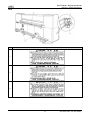
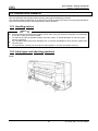
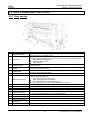
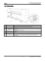
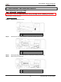
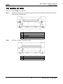
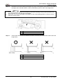
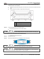
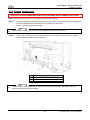
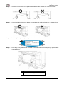
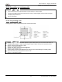
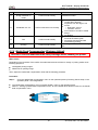
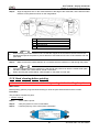
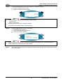
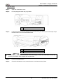
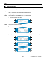
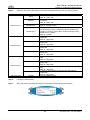
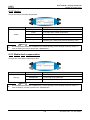
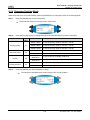
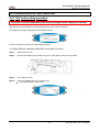
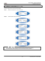
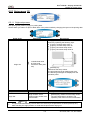
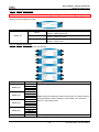
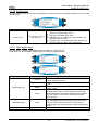
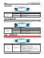
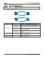
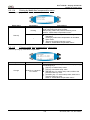
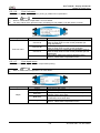
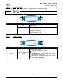
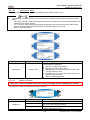
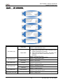
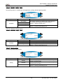
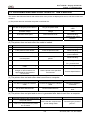
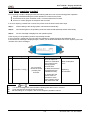
2.2 PARTS NAME AND FUNCTIONS
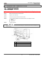
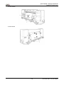
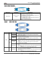
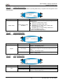
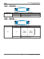
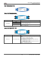
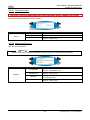
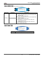
2.2.1 Front section
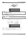
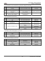
No.
Name
1
Operation panel
2
Front cover
3
Pressure roller
4
Platen
5
Media guide
6
Foot switch
7
Maintenance cover
8
9
10
11
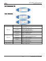
Waste fluid valve
Stand
Winding unit
Cushioning roller
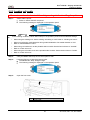
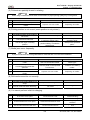
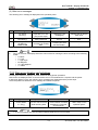
12
3-way cock cover
13
14
15
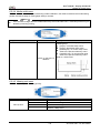
AC inlet
Interface connector
Foot switch connector
Network internet face
connector
Hard disk slot
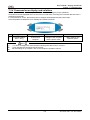
16
17
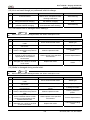
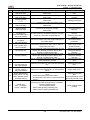
Function
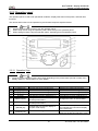
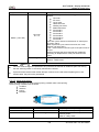
This panel is used to set operational conditions, the status of the printer, and other
functions. (Refer to : Operation panel)
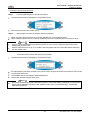
This cover keeps the operator safe from the drive parts of the printer while it is
operating. Open and/or close the cover only when performing the following operations.
•
Media setting and replacement
•
Cleaning inside the printer
•
Media jamming
Set inside the front cover. This roller is used to press the media from above and keep it
flat when printing.
Set inside the front cover. There is an ink drying device built in. On the surface, there is
a cutter groove for paper cutting.
This is used to feed the media smoothly when setting the media and when printing.
There is an ink drying device built in.
This switch is used to raise and lower the pressure roller.
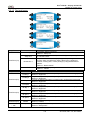
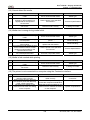
This cover protects the user from the internal components of the product. Opened
during the following conditions:
•
When switching the unit ON or OFF
•
When cleaning the print head surface.
•
When cleaning the print head inside the cover.
There is a waste fluid tray to collect waste fluid from the print head.
Opened when discharging waste fluid from the waste fluid tank. This is normally closed.
This stand is used to install the printer on a flat surface.
Winds and collects the printed media.
Used to guide the printed media to the winding unit.
Cover to protect operators from the internal mechanism of the product. Open when the
print head is cleaned. Normally this cover should be closed.
Insert the power cable plug.
Connector to connect Centronics Interface.
Connector to set foot switch cable.
Connector to connect Ethernet cable.
For attaching the optional hard disk. When the hard disk is not used, close the cover.
25
AP-75102, Rev. 2.0, 28/11/2007