1
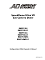
SpeedDome Ultra VII
22x Camera Dome
RAS915LS
RAS915LS-1
RAS916LS
RAS916LS-1
RAS916WLS
RAS916WLS-1
Configuration Utility Operator’s Manual
8200-0184-02 D
SpeedDome® Ultra VII
22x Camera Dome
Configuration Utility Operator’s Manual
Version – 0710-0147-0107
EQUIPMENT MODIFICATION CAUTION
Equipment changes or modifications not expressly approved by Sensormatic Electronics Corporation, the party
responsible for FCC compliance, could void the user's authority to operate the equipment and could create a
hazardous condition.
FCC COMPLIANCE
This equipment has been tested and complies with the limits for a Class A digital device, according to Part 15 of the
FCC Rules. These limits provide reasonable protection against harmful interference when the equipment operates in a
commercial environment. This equipment generates, uses, and can radiate radio frequency energy, and, if not
installed and used according to these instructions, may cause harmful interference to radio communications.
Operation of this equipment in a residential area is likely to cause harmful interference. If this equipment is used in a
residential area, users must correct the interference at their own expense.
LIMITED RIGHTS NOTICE
For units of the Department of Defense, all documentation and manuals were developed at private expense and no
part of it was developed using Government Funds. The restrictions governing the use and disclosure of technical data
marked with this legend are set forth in the definition of "limited rights" in paragraph (a) (15) of the clause of DFARS
252.227.7013. Unpublished - rights reserved under the Copyright Laws of the United States.
SOFTWARE LICENSE AGREEMENT
A Software License Agreement appears in Appendix S of this manual. Please read it carefully. Using the SpeedDome
Ultra VII Camera Dome Configuration Utility software indicates that you accept the terms and conditions of this
agreement.
NOTICE
The information in this manual was current when published. The manufacturer reserves the right to revise and
improve its products. All specifications are therefore subject to change without notice.
© Copyright 2003
Sensormatic Electronics Corporation
Under copyright laws, the contents of this manual may not be copied, photocopied, reproduced, translated or reduced
to any electronic medium or machine-readable form, in whole or in part, without prior written consent of Sensormatic
Electronics.
American Dynamics and SpeedDome are trademarks or registered trademarks of Sensormatic Electronics Corporation.
Product names mentioned herein may be trademarks or registered trademarks of other companies.
Thank you for using American Dynamics products. We support our products through an extensive and worldwide
network of dealers. The dealer, through whom you originally purchased this product, is your point of contact if you
have a need for service or support. Our dealers are fully empowered to provide the very best in customer service and
support. Dealers should contact American Dynamics at (800) 507-6268 or (561) 912-6259, or on the web at
www.americandynamics.net.
02/2004 - BSL
PN-8200-0184-02, Rev. D
TABLE OF CONTENTS
PREFACE: BEFORE YOU BEGIN ...................................................................................................................................... V
What’s In This Manual? ................................................................................................................................................... vi
Text Conventions ............................................................................................................................................................ vii
Related Documents ........................................................................................................................................................ vii
Getting Help .................................................................................................................................................................... vii
CHAPTER 1: USING THE DOME CONFIGURATION UTILITY....................................................................................... 1–1
What is the Dome Configuration Utility? ....................................................................................................................... 1–2
Starting the Dome Configuration Utility ......................................................................................................................... 1–2
Working with the Dome Configuration Utility ................................................................................................................. 1–3
Entering the Dome's Password ..................................................................................................................................... 1–3
Restoring Factory Settings............................................................................................................................................ 1–4
Exiting the Configuration Utility ..................................................................................................................................... 1–5
Accessing the Quick Set Menu ..................................................................................................................................... 1–5
Where To Go Next ........................................................................................................................................................ 1–7
Keeping Records for the Dome's Settings .................................................................................................................... 1–8
CHAPTER 2: CONFIGURING PAN, TILT, ZOOM, AND SYNCHRONIZATION OPTIONS ............................................. 2–1
Overview of Pan / Tilt / Zoom/Synchronization Options Screen.................................................................................... 2–2
Setting the Automatic “Flip” Feature ............................................................................................................................. 2–2
Adjusting the Zoom Stop Settings................................................................................................................................. 2–3
Configuring the Line Lock Setting ................................................................................................................................. 2–4
Configuring the Freeze Frame Setting .......................................................................................................................... 2–5
Configuring Auto Iris/Auto Focus Resume Settings ...................................................................................................... 2–6
What To Do Next .......................................................................................................................................................... 2–7
CHAPTER 3: CONFIGURING CAMERA FEATURES ..................................................................................................... 3–1
Overview of Camera Settings ....................................................................................................................................... 3–1
Adjusting White Balance Settings ................................................................................................................................. 3–2
Working with AGC and Open Shutter Settings.............................................................................................................. 3–3
What To Do Next .......................................................................................................................................................... 3–6
CHAPTER 4: CONFIGURING ALARMS, AREAS, HOME, PRIVACY SETTINGS, PRESETS AND SCAN LIMITS ....... 4–1
Overview of Alarms, Areas, Home, North Position, Preset, Privacy, and Scan Limit Settings ...................................... 4–2
Configuring Alarm Actions............................................................................................................................................. 4–3
Configuring Normal Input States for Alarms.................................................................................................................. 4–5
Assigning the Dome’s Home Position ........................................................................................................................... 4–6
Setting the North Position ............................................................................................................................................. 4–8
Programming Area Boundaries..................................................................................................................................... 4–9
Establishing Privacy Zones ......................................................................................................................................... 4–11
Programming Presets ................................................................................................................................................. 4–16
Establishing Scan Limits ............................................................................................................................................. 4–17
What To Do Next ........................................................................................................................................................ 4–20
CHAPTER 5: CONFIGURING TEXT DISPLAYED ON-SCREEN .................................................................................... 5–1
Overview of On-Screen Text Display Settings .............................................................................................................. 5–1
Displaying or Hiding Status Information ........................................................................................................................ 5–2
Displaying or Hiding All Name Information.................................................................................................................... 5–3
Displaying Diagnostic Tests During Reset .................................................................................................................... 5–4
Displaying Direction Indicators...................................................................................................................................... 5–5
Configuring the Display of Name Information................................................................................................................ 5–6
Assigning or Changing Name Information..................................................................................................................... 5–7
Changing the Settings for Text Displayed On-Screen................................................................................................... 5–9
What To Do Next ........................................................................................................................................................ 5–11
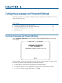
CHAPTER 6: CONFIGURING LANGUAGE AND PASSWORD SETTINGS ....................................................................6-1
Overview of Language and Password Settings..............................................................................................................6-1
Selecting a Language for Dome Messages and Prompts ..............................................................................................6-2
Setting and Enabling the Dome Password.....................................................................................................................6-3
What To Do Next ...........................................................................................................................................................6-4
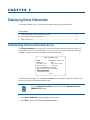
CHAPTER 7: DISPLAYING DOME INFORMATION .........................................................................................................7-1
Understanding the Dome Information Screen ................................................................................................................7-1
Viewing Dome Operating Statistics................................................................................................................................7-2
What To Do Next ...........................................................................................................................................................7-3
APPENDIX A: SENSORNET AND RS-422 PROTOCOLS COMMAND SUMMARY ...................................................... A–1
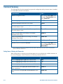
Command Summary .................................................................................................................................................... A–2
Supported Controllers and Matrix Switching Systems.................................................................................................. A–3
Performance Notes ...................................................................................................................................................... A–6
APPENDIX B: MANCHESTER PROTOCOL COMMAND SUMMARY ........................................................................... B–1
Command Summary .................................................................................................................................................... B–2
Supported Controllers .................................................................................................................................................. B–4
Performance Notes ...................................................................................................................................................... B–4
APPENDIX C: PELCO COAXITRON AND “P” PROTOCOLS COMMAND SUMMARY................................................ C–1
Supported SpeedDome Ultra VII Features................................................................................................................... C–2
Pelco Command Summary .......................................................................................................................................... C–3
Performance Notes ...................................................................................................................................................... C–4
Tested Pelco Equipment .............................................................................................................................................. C–4
Supported Pelco Features ........................................................................................................................................... C–4
APPENDIX D: PANASONIC UP-THE-COAX (UTC) PROTOCOL COMMAND SUMMARY........................................... D–1
Supported SpeedDome Ultra VII Features................................................................................................................... D–2
Panasonic UTC Command Summary .......................................................................................................................... D–3
Performance Notes ...................................................................................................................................................... D–4
Programming Presets .................................................................................................................................................. D–4
Tested Panasonic Equipment ...................................................................................................................................... D–5
APPENDIX E: AD UP-THE-COAX (UTC) PROTOCOL COMMAND SUMMARY ........................................................... E–1
Command Summary .................................................................................................................................................... E–2
Supported Keyboards .................................................................................................................................................. E–4
Performance Notes ...................................................................................................................................................... E–4
APPENDIX F: VICON COMMAND SUMMARY................................................................................................................F–1
Supported SpeedDome Ultra VII Features....................................................................................................................F–1
Vicon Command Summary ...........................................................................................................................................F–2
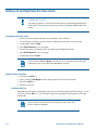
Operating the Dome Configuration Menu......................................................................................................................F–3
Setting Left and Right Auto Pan Scan Limits ................................................................................................................F–4
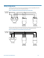
Wiring Configurations....................................................................................................................................................F–5
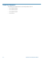
Tested Vicon Equipment ...............................................................................................................................................F–6
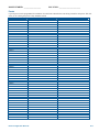
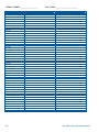
APPENDIX R: DOME CONFIGURATION RECORDS..................................................................................................... R–1
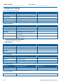
Configuration Settings.................................................................................................................................................. R–2
Pan / Tilt / Zoom / Sync Options ............................................................................................................. R–2
Camera Functions ................................................................................................................................... R–2
Set Alarm Actions.................................................................................................................................... R–2
Set Alarm States ..................................................................................................................................... R–2
Set Home Position................................................................................................................................... R–2
Set North Position ................................................................................................................................... R–2
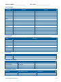
Area Boundaries...................................................................................................................................... R–3
Privacy Zones.......................................................................................................................................... R–3
Scan Limits .............................................................................................................................................. R–3
On-Screen Text Display .......................................................................................................................... R–3
Text Attribute Options.............................................................................................................................. R–3
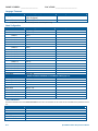
Language Password................................................................................................................................ R–4
Name Configuration ................................................................................................................................ R–4
Dome Information.................................................................................................................................... R–4
Presets .................................................................................................................................................... R–5
APPENDIX S: SOFTWARE LICENSE AGREEMENT..................................................................................................... S–1
SPEEDDOME ULTRA VII GLOSSARY
INDEX
iv
SpeedDome Ultra VII Operator's Manual
PREFACE
Before You Begin
This preface provides important information that you should be familiar with before using the
SpeedDome Ultra VII camera dome. It includes a document overview, text conventions, a list of
related documents, and how to obtain product help.
In This Preface
•
•
•
•
What’s In This Manual?..................................................................................................vi
Text Conventions ...........................................................................................................vii
Related Documents ........................................................................................................vii
Getting Help ...................................................................................................................vii
v
What’s In This Manual?
The SpeedDome Ultra VII Configuration Utility Operator's Manual is organized as follows:
• Chapter 1:Using the Dome Configuration Utility, describes how to use the SpeedDome Ultra VII
Camera Dome configuration utility.
• Chapter 2: Configuring Pan, Tilt, Zoom, and Synchronization Options, describes how to set the
“flip” feature, zoom stop, line lock, Freeze Frame and resuming auto iris/auto focus mode settings.
• Chapter 3: Configuring Camera Features, describes how to configure camera settings to improve
color and low-light performance.
• Chapter 4: Configuring Alarms, Areas, Home, Privacy Settings, Presets and Scan Limits,
describes how to configure settings associated with alarm inputs, the home position, and the North
setting. In addition, you can also set the boundaries for up to 16 areas, establish left and right scan
limits, as well as program presets and Privacy Zones.
• Chapter 5: Configuring Text Displayed On-Screen, describes how to configure settings
associated with displaying text on-screen. This includes names and status information, as well as
the text format and direction indicators.
• Chapter 6: Configuring Language and Password Settings, describes how to set the language for
the menus and prompts. It also describes how to set and enable a password to prevent unauthorized
use of the configuration utility.
IMPORTANT
If Portuguese is the selected language, the characters “ã” and “õ ” are not available for
display on-screen. This is due to a limitation of the dome’s text overlay chip.
• Chapter 7: Displaying Dome Information, explains how to display essential information about
your dome if service should be required.
• Appendix A: SensorNet and RS-422 Protocols Command Summary, provides information about
commands specific to using the dome in a SensorNet or RS-422 environment.
• Appendix B: Manchester Command Protocol Summary, provides information about commands
specific to using the dome in a Manchester environment.
• Appendix C: Pelco Coaxitron and “P” Protocols Command Summary, provides information
about features and commands supported by Pelco Coaxitron and “P” protocols.
• Appendix D: Panasonic Up-the-Coax (UTC) Protocol Command Summary, provides
information about features and commands supported by Panasonic UTC protocol.
• Appendix E: AD Up-the-Coax (UTC) Protocol Command Summary, provides information about
features and commands supported by AD UTC protocol.
• Appendix F: Vicon Protocol Command Summary, provides information about features and
commands supported by Vicon protocol.
• Appendix R: Dome Configuration Records, provides a convenient place for listing the
configuration information associated with your camera dome.
• Appendix S: Software License Agreement, lists the terms and conditions for using this product.
vi
SpeedDome Ultra VII Operator's Manual
Text Conventions
This book uses text in different ways to identify different kinds of information.
Bold Italics
Used for terms specific to the system, and text that requires special
emphasis, for example Preset.
Italics
Used for menu selections or settings, for example, On-screen Text
Display.
Bold
Used for names of buttons, for example, Zoom.
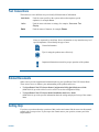
Notes are separated by ruled lines. Notes call attention to any items that may be of
special importance. Icons identify the type of note.
General information
Tips for using the product more effectively
Important information essential to proper operation of the product
Related Documents
Other sources provide supplemental information about your SpeedDome Ultra VII Camera Dome.
These sources serve to enhance your understanding of the product and its use.
• The SpeedDome Ultra VII Camera Dome Configuration Utility Quick Reference Guide
(8200-0184-03) provides a brief overview of how to use the configuration utility.
• The SpeedDome Ultra VII Camera Dome Installation and Service Guide
(8200-0184-01) provides specific information about the wiring and physical set up of the camera
dome.
Getting Help
If you have a question about the operation of this product and cannot find the answer in this manual,
consult with your supervisor. If your supervisor cannot answer your question, contact your Sales
Representative.
Preface
vii
N O T E S :
viii
SpeedDome Ultra VII Operator's Manual
CHAPTER 1
Using the Dome Configuration Utility
The SpeedDome Ultra VII 22x camera dome is an optical zoom camera enclosed in a compact dome
housing. The camera dome supports advanced features such as 11X digital zoom (up to 242X total
zoom), open shutter settings, privacy zones, and direction indicators. The Dome Configuration Utility
is used to customize the camera dome's settings.
This chapter introduces you to the Dome Configuration Utility. It explains how to start the utility,
navigate through the menus, and change settings. It also explains where to find specific information
about customizing dome settings.
In This Chapter
•
•
•
•
•
•
•
•
•
What is the Dome Configuration Utility? ....................................................................1–2
Starting the Dome Configuration Utility......................................................................1–2
Working with the Dome Configuration Utility ............................................................1–3
Entering the Dome's Password..................................................................................... 1–3
Restoring Factory Settings ........................................................................................... 1–4
Exiting the Configuration Utility .................................................................................1–5
Accessing the Quick Set Menu ....................................................................................1–5
Where To Go Next ......................................................................................................1–7
Keeping Records for the Dome's Settings ...................................................................1–8
What is the Dome Configuration Utility?
The Dome Configuration Utility provides a means to setting features for your camera dome via a text
overlay menu. You access this utility using a keystroke combination on your camera controller. The
utility provides settings relating to camera functions, alarms, text display, privacy zones, direction
indicators and password protection. Some items supplement similar features that may be available
through your controller.
Refer to your controller operating instructions for information about button locations mentioned in
this document.
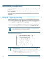
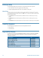
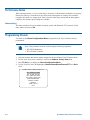
Starting the Dome Configuration Utility
The Dome Configuration Utility is started using a series of keyboard commands. Depending on the
controller and network protocol in use, the commands required to start the configuration utility differ.
• If the dome is installed in a SensorNet or RS-422 environment, press and hold Iris Open, press
and hold a Focus button (near or far), then press Zoom Out.
• If the dome is installed in a Manchester environment, place the controller in programming mode
(turn the keyswitch to Prog or disable the lock), enter 66, then press Set Preset (Set Shot).
Note: Other protocols and controllers may be supported. The Appendixes located at
the end of this manual provide additional information.
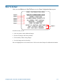
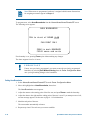
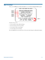
The following menu appears on the monitor:
DOME CONFIGURATION MENU
PAN/TILT/ZOOM/SYNC OPTS
CAMERA FUNCTIONS
ALARMS/AREAS/PRESETS/PZ
ON-SCREEN TEXT DISPLAY
LANGUAGE / PASSWORD
DOME INFORMATION
RESET TO FACTORY SETTINGS
QUIT WITHOUT SAVING
EXIT AND SAVE CHANGES
IMPORTANT
If you have password protection enabled for the configuration utility, the Enter
Password screen appears first. You must correctly enter the password before the
Dome Configuration Menu will appear. For information about entering the
password, refer to Entering the Dome's Password on page 1–3.
1–2
SpeedDome Ultra VII Operator's Manual
Working with the Dome Configuration Utility
Once the Dome Configuration Menu is displayed, you may select a menu item, and then modify the
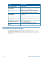
settings you want to change. The following table summarizes the controller commands for SensorNet,
RS-422, and Manchester protocols. For combination keystrokes, press and hold each button in
sequence, then release.
If you want to …
Use …
Move the highlight bar.
Pan/Tilt
Select the highlighted item on the screen.
Focus
Increase the value of the selected setting or display the next
choice for the setting
Zoom In
Decrease the value of the selected field, or display the
previous choice for the field.
Zoom Out
During naming, move the cursor to the right of the current
character in the name.
Zoom In
During naming, move the cursor to the left of the current
character in the name.
Zoom Out
Save changes and exit the utility from any screen.
Iris Close, then Focus
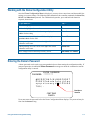
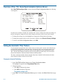
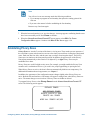
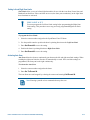
Entering the Dome's Password
A dome password can be used to prevent unauthorized users from starting the configuration utility. If
password protection is enabled the Enter Password screen appears when the command to start the
configuration utility is entered.
ENTER PASSWORD
PASSWORD: ********
ABCDEFGHIJKLMNOPQRST
UVWXYZabcdefghijklmn
opqrstuvwxyz 0123456
789/CONTINUE
CANCEL
Blank Space
Character
Users must enter the password before the Dome Configuration Menu displays. The password may be
from 1 to 8 characters long.
Using the Dome Configuration Utility
1–3
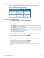
To enter the password using SensorNet, RS-422, or Manchester protocols:
1. Use the Pan/Tilt control to move the highlight the appropriate character.
2. Press Focus to select the highlighted character.
If you need to change a character that has been entered:
• Zoom In moves the cursor to the right in the Password field.
• Zoom Out moves the cursor to the left in the Password field.
As each character in the password is selected, asterisks (*) appear in the Password field. When you
have finished entering the password, select Continue. If the correct password has been entered, the
Dome Configuration Menu appears. If the correct password was not entered, the Enter Password
screen remains on the monitor.
If you do not want to start the configuration utility, select Cancel to return to normal dome
operation.
IMPORTANT
If you forget the password, contact your Sales Representative for assistance.
For information about programming and enabling password protection, see Chapter 6.
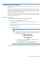
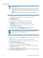
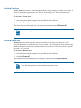
Restoring Factory Settings
Some screens provide a choice to restore factory settings. This choice applies only to those settings currently
displayed on the screen. To reset all configuration settings, choose Reset to Factory Settings from the
Dome Configuration Menu. The following prompt appears:
Reset to Factory Settings
No
Press Zoom to display the options.
• If you want to restore the factory settings, select Yes.
• If you do not want to restore the factory settings, select No.
Press Focus to accept the displayed option.
I M P O R T A N T
Selecting Reset to Factory Settings from the Dome Configuration Menu does not change
the following settings: Camera Name, Alarm Names, Area Names, Preset Names, Pattern
Names, Area Boundaries, Privacy Zones, and Presets. To reset names to the default settings, see
Chapter 5: Configuring Text Displayed On-Screen.
1–4
SpeedDome Ultra VII Operator's Manual
Exiting the Configuration Utility
Under SensorNet, RS-422, and Manchester protocols, you may save your changes and exit the utility from any
screen by pressing and holding Iris Close, then pressing Focus. From the Dome Configuration Menu, you
have two choices for exiting the utility: Exit and Save Changes or Quit Without Saving. Use the
Pan/Tilt control to move the highlight bar up and down on the screen.
• If you want to keep the changes you made, move the highlight bar to Exit and Save Changes, and select.
The utility closes.
• If you want to exit without making changes, move the highlight bar to Quit Without Saving, and select.
The following prompt appears on the screen:
Data Not Saved. Quit Anyway?
No
Press Zoom to display the options.
• To cancel the changes, select Yes.
• To keep the changes, select No. If you choose No, the Dome Configuration Menu is displayed.
Press Focus to accept the displayed option.
I M P O R T A N T
The following settings do not restore when selecting Quit Without Saving from the Dome
Configuration Menu: Area Boundaries and AGC/Shutter Limit.
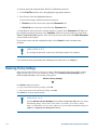
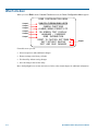
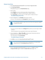
Accessing the Quick Set Menu
SpeedDome Ultra VII provides a Quick Set Menu for commonly used features and functions when
used with compatible controllers. This allows you to change or activate features without starting the
dome configuration menu.
0
1
2
3
4
15
16
17
20
TOGGLE QUICK SET MENU
DOME CONFIG MENU
AUTO IRIS/AUTO FOCUS
FLIP
PEEL PATTERN
SMOOTH SCAN
STEPPED SCAN
RANDOM SCAN
DOME INFORMATION
To access a feature on the menu, enter the number and press the Quick Set button (varies by
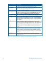
controller). The following provides a description of the available options.
Using the Dome Configuration Utility
1–5
Quick Set Command
Description
0+Quick Set
Toggles between displaying and hiding the quick set menu.
1+ Quick Set
Displays the SpeedDome Ultra configuration menu. Refer to the dome
manual for information about the available settings.
2+ Quick Set
Resumes Auto Focus/Auto Iris mode.
3+ Quick Set
Rotates the SpeedDome 180° from its current pointing direction. This is
the same as pressing the Flip button on controllers with that feature.
4+ Quick Set
Runs the default Apple Peel Pattern continuously.
15+ Quick Set
Initiates a smooth scan between the left and right scan limits, starting at
the left scan limit. If no scan limits have been set, initiates a smooth 360°
clockwise rotation around the dome axis using the current tilt, zoom and
focus settings.
16+ Quick Set
Initiates a scan between the left and right scan limits pausing briefly
every 10° (at 1x zoom), starting at the left scan limit. When the right scan
limit is reached, the scan is reversed. If no scan limits have been set,
initiates a clockwise rotation around the dome axis pausing briefly every
10° (at 1x zoom) for 3 seconds using the current tilt, zoom and focus
settings.
17+ Quick Set
Initiates a scan between the left and right scan limits pausing randomly
between the limits. If no scan limits have been set, initiates a clockwise or
counter-clockwise rotation around the dome axis using the current tilt,
zoom and focus settings. The dome pauses randomly as it rotates around
the axis.
20+ Quick Set
Displays the Dome Information screen available through the dome
configuration menu.
Refer to your controller instructions to determine if the Quick Set Menu is supported.
1–6
SpeedDome Ultra VII Operator's Manual
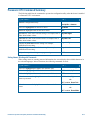
Where To Go Next
Now that you understand how to start and work with the Dome Configuration Utility, you are ready
to begin changing the settings for your dome. Use the following chart to determine which chapters
you should use next.
Chapter
Topics Covered
Chapter 2: Configuring Pan, Tilt,
Zoom, and Synchronization Options
− Set the “flip” feature to rotate the dome 180°
− Set the first zoom stop (22X or 33X) and maximum zoom (up
to 242X)
− Set line lock to prevent vertical rolling when switching
between cameras
Chapter 3: Configuring Camera
Features
− Enable automatic or manual White Balance settings (red and
blue values)
− Set the open shutter options to improve camera performance in
low light situations
− Enable automatic or manual Gain settings and set maximum
gain values
Chapter 4: Configuring Alarms,
− Set alarm actions to initiate a preset, pattern, or no action when
Areas, Home, Privacy Settings, Presets
alarm conditions are detected
and Scan Limits
− Configure normal input states for alarms to be open or closed
− Send input states to host controller
− Set a “home” position for dome
− Establish a North position for use with the direction indicators
− Program Privacy Zones to prevent operators from viewing
restricted areas
− Program area boundaries
− Program presets
− Set scan limits
Chapter 5: Configuring Text
Displayed On-Screen
− Display or hide dome status information
− Display or hide camera, preset, pattern, area or alarm name
information
− Display diagnostic information or “splash” screen during dome
reset
− Display direction indicators
− Assign names to camera, presets, patterns, areas, and alarms
− Reset all names to factory defaults
− Set text attributes (outline and translucent characters)
Chapter 6: Configuring Language and − Choose the language for the menus and prompts
Password Settings
− Set a password to limit access to the Dome Configuration
Utility
− Enable or disable password protection
Chapter 7: Displaying Dome
Information
Using the Dome Configuration Utility
− Display dome version information
− Display dome performance statistics
1–7
Chapter
Topics Covered
Appendix A: SensorNet and
RS-422 Command Summary
− Summarizes the controller commands available for
SensorNet/RS-422
Appendix B: Manchester
Command Summary
− Summarizes the controller commands available for Manchester
Appendix C: Pelco Coaxitron and “P”
Protocols Command Summary
− Summarizes the controller commands available for Pelco
Coaxitron and “P” protocols
− Performance limitations for Manchester
− Performance limitations for Coaxitron and “P” protocols
Appendix D: Panasonic Up-the-Coax
Command Summary
− Summarizes the controller commands available for Panasonic
UTC protocol
− Performance limitations for UTC protocol
Appendix E: AD Up-the-Coax
Command Summary
− Summarizes the controller commands available for AD-UTC
protocol
Appendix F: Vicon Protocol
Command Summary
− Summarizes the controller commands available for the Vicon
protocol
Appendix R: Dome Configuration
Records
− Lists the default dome settings
Appendix S: Software License
Agreement
− Lists the terms and conditions for using this product
− Provide space for documenting changes to settings
Keeping Records for the Dome's Settings
Keep records for each SpeedDome Ultra VII camera dome installed at your facility.
Appendix R: Dome Configuration Records summarizes the default values for each configuration
setting. Space is provided for documenting the settings you change. Note any changes you make to
the dome settings.
1–8
SpeedDome Ultra VII Operator's Manual
CHAPTER 2
Configuring Pan, Tilt, Zoom, and Synchronization
Options
This chapter describes the use of the Pan/Tilt/Zoom/Sync Opts menu. Use this screen to set the
Auto Flip feature, configure the Zoom Stop settings, and set the Line Lock option.
In This Chapter
•
•
•
•
•
•
•
Overview of Pan / Tilt / Zoom/Synchronization Options Screen ................................ 2–2
Setting the Automatic “Flip” Feature...........................................................................2–2
Adjusting the Zoom Stop Settings ...............................................................................2–3
Configuring the Line Lock Setting ..............................................................................2–4
Configuring the Freeze Frame Setting .........................................................................2–5
Configuring Auto Iris/Auto Focus Resume Settings....................................................2–6
What To Do Next .........................................................................................................2–7
Overview of Pan / Tilt / Zoom/Synchronization Options Screen
When Pan/Tilt/Zoom/Sync Opts is selected from the Dome Configuration Menu, the following
screen appears:
PROPORTIONAL FLIP
1ST ZOOM STOP X
MAX TOTAL ZOOM X
LINE LOCK
FREEZE FRAME
I/F RETURN TO AUTO
OFF/ON
33/22
44...242
ON/OFF
OFF/ON
OFF/ON/
IRIS/FOCUS
Use this screen to enable or disable the “automatic flip” feature, configure the zoom stop settings, set
the line lock options, change the freeze frame settings, and return to auto iris/auto focus settings.
• To change the settings, move the highlight bar to appropriate field and make the changes.
• To change the settings for this screen to the factory defaults, select Reset to Factory Settings.
• To return to the Dome Configuration Menu, select Exit.
Setting the Automatic “Flip” Feature
Use the automatic (proportional) “flip” feature when you need to track someone who walks directly
under the dome and continues on the other side. You start the flip by moving the tilt control to its
lower limit and holding for a brief period. When the flip engages, the dome automatically rotates
180°. You may then continue to track the person as long as the tilt control stays in its lower limit.
Once the tilt control is released, the dome resumes normal operation.
The dome is initially installed with the automatic flip feature disabled. In this situation, the dome
stops when the tilt down reaches its lower limit.
Changing the Automatic Flip Setting
1. Select Pan/Tilt/Zoom/Sync Opts from the Dome Configuration Menu.
The highlight bar appears on the Proportional Flip setting.
2. Change the setting.
• Select On to enable the flip feature.
• Select Off to disable the flip feature.
The default setting is Off.
3. Select Exit. The Dome Configuration Menu appears. Continue with What To Do Next on page
2–7.
2–2
SpeedDome Ultra VII Operator's Manual
Adjusting the Zoom Stop Settings
The SpeedDome Ultra VII includes a 22X optical zoom camera with 11X digital zoom capability.
The maximum possible zoom is 242X. Zoom stop settings define how the zoom function is
partitioned. Depending on the current zoom level, the camera will either stop at the first zoom stop
setting or continue to the maximum zoom setting. The following example explains how zoom stop
settings work.
The default camera settings are 33X for the first zoom stop setting and 88X for the maximum zoom
setting. If the current zoom level is less than 33X, pressing Zoom In continuously causes the zoom to
stop at 33X. If the zoom level is 33X or greater, pressing Zoom In continuously causes the zoom to
stop at the maximum zoom setting of 110X. The second zoom stop remains in effect until the zoom
function is reduced to less than the first zoom stop setting (33X) and the zoom button is released for
one second or longer. To achieve higher zoom levels, change the maximum zoom setting.
2X is the margin of error for the zoom stop settings.
Changing the Zoom Stop Settings
1. Select Pan/Tilt/Zoom/Sync Opts from the Dome Configuration Menu.
2. To change the first zoom stop, continue with step 3. To change the maximum zoom setting,
continue with step 5.
3. Move the highlight bar to 1st Zoom Stop X. Change the setting.
• Select 22 to set the first zoom stop to 22X magnification.
• Select 33 to set the first zoom stop to 33X magnification.
The default setting is 33X.
4. To change the maximum zoom setting, continue with step 5. Otherwise, continue with step 6.
5. Move the highlight bar to the Max Total Zoom X setting. Change the value of the setting.
• The values for the setting are: 44, 66, 88, 110, 132, 154, 176, 198, 220, and 242X
magnification.
The default setting is 88X.
6. Select Exit. The Dome Configuration Menu appears. Continue with What To Do Next on page
2–7.
Configuring Pan, Tilt, Zoom, and Synchronization Options
2–3
Configuring the Line Lock Setting
Use the Line Lock setting to prevent vertical rolling or adjust the appearance of overlay text on color
monitors.
If you experience problems with vertical video rolling when switching multiple cameras to a single
monitor, enabling the Line Lock setting phase locks the video with the AC power line. All cameras
connected to the same power supply will be synchronized. This synchronization prevents the video
from rolling vertically when cameras are switched.
With the Line Lock disabled, the appearance of text displayed on color monitors may be improved.
However, the video will no longer be phase locked with the AC power line. Video may roll vertically
when switching between cameras.
Changing the Line Lock Setting
1. Select Pan/Tilt/Zoom/Sync Opts from the Dome Configuration Menu.
2. Move the highlight bar to Line Lock. Change the setting.
• Select On to enable the line lock. This phase locks the video with the AC power line to
prevent video rolling.
• Select Off to disable the line lock. This stops the phase lock, but may improve the appearance
of text displayed on color monitors.
The default setting is On.
IMPORTANT
Changing the Line Lock setting is not immediate. The dome must reinitialize
(reset) for the change to take place. When the configuration utility is exited,
the following prompt appears:
DOME MUST RESET TO
CHANGE LINELOCK MODE.
•
•
RESET DOME NOW?
NO
If you do not want to reinitialize the dome, select No. Changes to the
Line Lock setting will not take effect.
If you want to reinitialize the dome, select Yes. Changes to the Line
Lock setting will take effect when the dome finishes the reset.
3. Select Exit. The Dome Configuration Menu appears. Continue with What To Do Next on page
2–7.
2–4
SpeedDome Ultra VII Operator's Manual
Configuring the Freeze Frame Setting
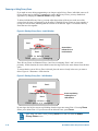
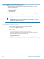
If you need to maintain a static image when calling automatic functions, such as presets or patterns,
use the Freeze Frame setting. This prevents the display of the dome movement and lens adjustments
from being displayed on-screen while the preset or pattern is being sought.
When the Freeze Frame setting is enabled, the scene currently displayed on the monitor will be
preserved (frozen) on-screen until the pattern or preset is ready for display. The image then switches
smoothly to the new scene. You may want to use this setting if using a digital video recorder.
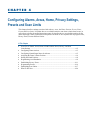
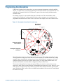
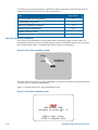
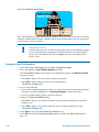
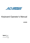
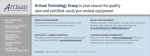
For example, if the dome is installed in a lobby of a busy building, you may want to program presets
that show different areas in the lobby. Figure 2-1 shows a sample floor plan for the lobby.
Figure 2-1: Lobby Floor Plan
Entry
Security
Office Door
Waiting
Area
Dome
Reception
Desk
Hallway
Elevator
If Freeze Frame is disabled, each time the dome points to a different preset, you will see the dome’s
movement to the new scene, as well as any lens adjustments that are required. For example, if the
dome is currently pointing at Reception Desk, and the preset number assigned to the Entry is selected,
you will see a blur of motion as the dome quickly pans past other areas in the lobby before focusing
on the Entry scene.
If Freeze Frame is enabled, the current scene is displayed on-screen until all dome movement and
lens adjustments are complete. For example, the Reception Desk scene will be frozen on-screen until
the dome completes the movement and lens adjustments necessary to display the selected preset.
When the adjustments are finished, the Entry scene is automatically displayed.
Configuring Pan, Tilt, Zoom, and Synchronization Options
2–5
Changing the Freeze Frame Setting
1. Select Pan/Tilt/Zoom/Sync Opts from the Dome Configuration Menu.
2. Move the highlight bar to Freeze Frame. Change the setting.
• Select On to enable Freeze Frame. This freezes the current scene when presets or patterns are
selected.
• Select Off to disable Freeze Frame. This displays the dome motion and lens adjustments when
presets or patterns are selected.
The default setting is Off.
3. Select Exit. The Dome Configuration Menu appears. Continue with What To Do Next on page
2–7.
Configuring Auto Iris/Auto Focus Resume Settings
Normally, the camera’s iris and focus settings return to automatic mode when the dome moves a
minimum of one frame from its current pointing position. In some situations, you may want to
maintain specific iris and/or focus adjustments based upon your surveillance needs.
Use the I/F Return to Auto setting to configure the auto iris and auto focus resume settings. Four
settings are available.
Setting
Description
ON
Both return to auto iris and return to auto focus settings are enabled.
Moving the dome resumes auto mode for both iris and focus changes.
OFF
Both return to auto iris and return to auto focus settings are disabled.
Moving the dome does not resume auto mode for iris and focus changes.
IRIS
Only return to auto iris is enabled. Return to auto focus is disabled.
Moving the dome resumes auto iris mode without changing focus settings.
FOCUS
Only return to auto focus is enabled. Return to auto iris is disabled.
Moving the dome resumes auto focus mode without changing iris settings.
Changing the Auto Iris/Auto Focus Resume Setting
1. Select Pan/Tilt/Zoom/Sync Opts from the Dome Configuration Menu.
2. Move the highlight bar to I/F Return to Auto. Change the setting.
• Select On to enable both resume auto iris and resume auto focus.
• Select Off to disable both resume auto iris and resume auto focus.
• Select Iris to enable resume auto iris only.
• Select Focus to enable resume auto focus only.
The default setting is On.
3. Select Exit. The Dome Configuration Menu appears. Continue with What To Do Next on page
2–7.
2–6
SpeedDome Ultra VII Operator's Manual
What To Do Next
When you select Exit from the Pan/Tilt/Zoom screen, the Dome Configuration Menu appears.
DOME CONFIGURATION MENU
Chapter 2
Chapter 3
Chapter 4
Chapter 5
Chapter 6
Chapter 7
PAN/TILT/ZOOM/SYNC OPTS
CAMERA FUNCTIONS
ALARMS/AREAS/PRESETS/PZ
ON-SCREEN TEXT DISPLAY
LANGUAGE / PASSWORD
DOME INFORMATION
RESET TO FACTORY SETTINGS
QUIT WITHOUT SAVING
EXIT AND SAVE CHANGES
Chapter 1
From this screen you can:
• Select an option to make additional changes.
• Restore all settings to the factory defaults.
• Exit the utility without saving changes.
• Save the changes and exit the utility.
Move the highlight bar to an item and select it. Refer to the related chapter for additional information.
Configuring Pan, Tilt, Zoom, and Synchronization Options
2–7
N O T E S :
2–8
SpeedDome Ultra VII Operator's Manual
CHAPTER 3
Configuring Camera Features
This chapter describes the settings used to control the camera features. It describes how to change the
white balance settings, automatic gain control, and open shutter settings to improve camera
performance.
In This Chapter
•
•
•
•
Overview of Camera Settings ......................................................................................3–1
Adjusting White Balance Settings ...............................................................................3–2
Working with AGC and Open Shutter Settings ...........................................................3–3
What To Do Next ......................................................................................................... 3–6
Overview of Camera Settings
When Camera Functions is selected from the Dome Configuration Menu, the following screen
appears:
CAMERA FUNCTIONS
Auto White Bal
OFF/ON
W Bal Adj: Red 0-511
Blue 0-511
AGC/Shutter
Max Gain
Open Shutter(NTSC)0-28 dB
Open Shutter(PAL) 0-28 dB
Limit
1/2-1/60 s
2/3-1/50 s
RESET TO FACTORY SETTINGS
EXIT
From this screen you can adjust the white balance settings, set the IR mode for the camera, enable or
disable Wide Dynamic Range, set the automatic gain control (AGC) feature, adjust the AGC level,
and configure the open shutter settings.
• To change settings, move the highlight bar to the appropriate field and make the changes.
• To change the settings for this screen to the factory defaults, select Reset to Factory Settings.
• To return to the Dome Configuration Menu, select Exit.
Adjusting White Balance Settings
White balance is normally compensated for by the automatic white balance gain control. In some
lighting conditions, you may need to manually adjust the red and blue settings for optimal viewing.
When Automatic White Balance is enabled, the red and blue setting values are based on feedback
from the camera. When Automatic White Balance is disabled, the camera uses the red and blue
setting values to control the white balance. When Automatic White Balance is first switched from
On to Off, the red and blue values displayed are based on the current feedback from the camera. The
red and blue values range from 0 to 511. Changes occur in increments of 5.
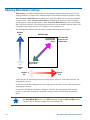
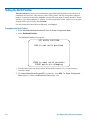
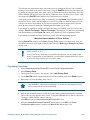
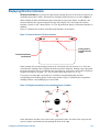
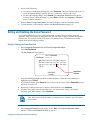
The following chart illustrates the red and blue settings relationship to white balance.
Maximum
Blue
WHITE BALANCE
On-screen Color
appears Magenta
(Purple)
511
Both Red and Blue
settings are set to
maximum values.
On-screen Color
appears Green
0
Minimum
Blue
Minimum 0
Red
511
Maximum
Red
As the value for the red setting increases, the image appears more red. As the value decreases, the
image appears less red.
As the value for the blue setting increases, the image appears more blue. As the value decreases, the
image appears less blue.
As the values for both the red and blue settings are increased, the image appears more magenta
(purple). As the values for both the red and blue settings are decreased, the image appears more
green.
Tip: Auto White Bal must be set to Off to manually change the Red and Blue settings.
Changes to the red and blue settings occur in increments of 5.
3–2
SpeedDome Ultra VII Operator's Manual
Changing Automatic White Balance Settings
1. Select Camera Functions from the Dome Configuration Menu. The highlight appears on the
Auto White Bal setting.
2. Change the setting.
• Select Off to manually adjust the red or blue settings. Continue with step 3.
• Select On for automatic white balance. Continue with step 7.
The default setting is On.
3. Do one of the following:
• To change the red setting, move the highlight bar to W Bal Adj: Red, then continue with
step 4.
• To change the blue setting, continue with step 5.
4. Adjust the red setting. The values range from 0 to 511.
There is no default value for the red setting.
5. Do one of the following:
• To change the blue setting, move the highlight bar to Blue, then continue with step 6.
• If you are finished making changes, continue with step 7.
6. Adjust the blue setting. The values range from 0 to 511.
There is no default value for the blue setting.
7. Select Exit. The Dome Configuration Menu appears. Continue with What To Do Next on
page 3–6.
Working with AGC and Open Shutter Settings
The SpeedDome Ultra VII dome provides settings for compensating for low-light scenes in color:
Automatic Gain Control and Open Shutter. Automatic Gain Control (AGC) amplifies the video signal
in scenes with minimal light. Many low-light scenes result in picture noise. As gain is increased, the
picture noise is also amplified.
When AGC is enabled, the camera automatically adjusts the gain setting value. When AGC is
disabled, no gain is applied to the video signal. This may make the video appear darker on the
monitor.
The gain setting for the camera differs from the maximum gain (Max Gain) setting available on the
Camera Functions menu. The Max Gain setting is an upper limit for how much gain can be
increased when AGC is enabled. The trade-off between picture level (brightness) and noise may be
adjusted by setting the Max Gain value. Lower values for Max Gain setting may result in a darker
picture with less noise. Higher values for Max Gain setting may result in a brighter picture with more
noise.
In addition to the AGC settings, you may also adjust the Open Shutter settings to improve dome
performance in low light conditions. For more information, continue with Understanding How
Advanced Shutter Settings Improve Low-Light Performance.
Configuring Camera Features
3–3
Understanding How Advanced Shutter Settings Improve Low-Light Performance
The camera dome supports the ability to view color images from extremely low-light situations. This
feature is called Open Shutter and is only in effect during low-light situations where an image would
not be obtainable otherwise. It does not affect the camera performance in normal or bright light
situations.
When the Open Shutter is enabled and the scene illumination is too low to obtain a clear image at the
normal video rate, the camera collects luminance information from multiple fields. As it does so, the
current video information is retransmitted until new information is available from the camera. Under
these conditions, moving objects will appear blurred, and still images may appear blurred, choppy,
and with more static than video obtained under normal lighting conditions.
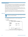
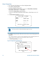
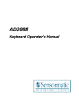
The Shutter Limit value sets the video update time in fractions of a second. Depending on the
lighting conditions, the video information may be updated more frequently, but no slower than the
limit set.
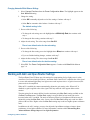
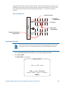
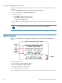
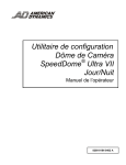
Figure 3–1 illustrates a Shutter Limit of 1/4.
Figure 3–1: Graphical view of Shutter Limit settings
Red Light
Red Light
250
msec
Red Light
250
msec
Green Light
180
msec
In this example, the dome receives information about the color of the traffic light. While the light is
red, the image is relatively static. With the shutter limit set to 1/4 second (250 milliseconds), updated
red light information is transmitted at 1/4-second intervals. When the light changes from red to green,
updated light color information becomes available. The dome must now transmit information about
the green light. This update occurs as soon as the green light information is available. This may occur
before the 1/4-second interval elapses. In this example, the light changed to green after 180milliseconds. Thereafter the green light information is transmitted at 1/4-second intervals until new
light color information becomes available.
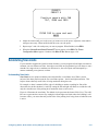
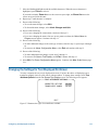
If the light were to change from red to green halfway through the field integration interval (125
milliseconds), it may appear that both the red and green lights are lit simultaneously. This situation is
illustrated in Figure 3–2.
Figure 3–2: Mixed field integration
Red Light
Red Light
250
msec
Red/Green Light
125
msec
Green Light
125
msec
Adjusting the Shutter Limit sets the update time used to maintain the image quality. If you want to
videotape an incident in low-light conditions, you may find that tape quality is not acceptable. To
ensure that the videotape quality is acceptable for possible prosecution purposes, you may want to test
the Shutter Limit settings under the expected lighting conditions.
3–4
SpeedDome Ultra VII Operator's Manual
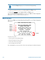
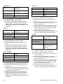
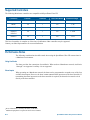
The Relationship between AGC and Open Shutter Settings
Table 3–1 explains which settings may be changed based on the current AGC/Shutter setting.
Table 3–1: AGC Maximum Gain and Shutter Limit settings
AGC/Shutter Setting
Max Gain
Limit
AGC Off
N/A
N/A
AGC On
0-28dB (NTSC)
N/A
0-29dB (PAL)
Open Shutter
0-28dB (NTSC)
1/2-1/60 (NTSC)
0-29dB (PAL)
2/3-1/50 (PAL)
Configuring AGC and Open Shutter Settings
1. Select Camera Functions from the Dome Configuration Menu.
2. Move the highlight to AGC/Shutter mode field. The highlight appears in the first field (AGC/
Mode).
3. Select one of the following:
• Select AGC On to set AGC to automatic mode. This allows you to adjust the maximum AGC
gain setting (in decibels). Continue with step 4.
• Select AGC Off to set the AGC to minimum level. You cannot adjust the maximum AGC gain
or shutter limit settings. Continue with step 7.
• Select Open Shutter to enable field integration. This allows you to adjust the maximum AGC
gain and shutter limit settings. Continue with step 4.
The default setting is Open Shutter.
4. Move the highlight to Max Gain field. Change the setting. The following settings are available:
• For NTSC cameras, the setting values range from 0 to 28dB.
• For PAL cameras, the setting values range from 0 to 28dB.
5. If you need to change the shutter limit setting, continue with step 6. Otherwise, continue with
step 7.
6. Move the highlight to the Limit field. Change the setting. The following settings are available:
• For NTSC cameras, the setting values range from 1/2 to 1/60.
• For PAL cameras, the setting values range from 2/3 to 1/50.
The default setting is 1/4 for NTSC and 1/4 for PAL.
7. Select Exit. The Dome Configuration Menu appears. Continue with What To Do Next on
page 3–6.
Configuring Camera Features
3–5
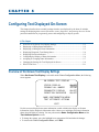
What To Do Next
When you select Exit from the Camera Functions screen, the Dome Configuration Menu appears.
DOME CONFIGURATION MENU
Chapter 2
Chapter 3
Chapter 4
Chapter 5
Chapter 6
Chapter 7
PAN/TILT/ZOOM/SYNC OPTS
CAMERA FUNCTIONS
ALARMS/AREAS/PRESETS/PZ
ON-SCREEN TEXT DISPLAY
LANGUAGE / PASSWORD
DOME INFORMATION
RESET TO FACTORY SETTINGS
QUIT WITHOUT SAVING
EXIT AND SAVE CHANGES
Chapter 1
From this screen you can:
• Select an option to make additional changes.
• Restore settings to the factory defaults.
• Exit the utility without saving changes.
• Save the changes and exit the utility.
Move the highlight bar to an item and select it. Refer to the related chapter for additional information.
3–6
SpeedDome Ultra VII Operator's Manual
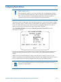
CHAPTER 4
Configuring Alarms, Areas, Home, Privacy Settings,
Presets and Scan Limits
This chapter describes settings associated with Alarms, Areas, the Home Position, Privacy Zones,
Presets and Scan Limits. It explains how to set a default action to run when a dome alarm occurs, as
well as how to define the normal alarm input states. It describes how to set a default position for the
dome and assign a dome position that corresponds with North. It also explains how to program Areas,
Privacy Zones, Presets and Scan Limits.
In This Chapter
•
•
•
•
•
•
•
•
•
•
Overview of Alarms, Areas, Home, North Position, Preset, Privacy, and Scan
Limit Settings ..............................................................................................................4–2
Configuring Alarm Actions..........................................................................................4–3
Configuring Normal Input States for Alarms...............................................................4–5
Assigning the Dome’s Home Position .........................................................................4–6
Setting the North Position ............................................................................................4–8
Programming Area Boundaries....................................................................................4–9
Establishing Privacy Zones ........................................................................................4–11
Programming Presets .................................................................................................4–16
Establishing Scan Limits............................................................................................4–17
What To Do Next .......................................................................................................4–20
Overview of Alarms, Areas, Home, North Position, Preset, Privacy, and
Scan Limit Settings
When Alarms/Areas/Home/Presets/PZ is selected from the Dome Configuration Menu, the
following screen appears:
ALARMS/AREAS/HOME/PRESETS/PZ
SET ALARM ACTIONS
SET ALARM STATES
SET HOME POSITION
SET NORTH POSITION
AREA BOUNDARIES
PRIVACY ZONES
PRESETS
SCAN LIMITS
EXIT
From this menu you can choose to configure alarm actions, configure normal states for alarm inputs,
assign the “home position”, establish the north position for the dome, set area boundaries, set privacy
zones, program presets and set scan limits.
• To make changes, select a menu item to display the associated settings.
• To change the settings, move the highlight bar to appropriate field and make the changes.
• To return to the Dome Configuration Menu, select Exit.
4–2
SpeedDome Ultra VII Operator's Manual
Configuring Alarm Actions
IMPORTANT
When operating on Manchester networks, the dome can be programmed to respond to
any of the four available alarm inputs. However, the dome cannot transmit alarm input
states to the host controller. If transmitting the alarm state to the host controller is
required, the alarm device must be wired directly to the host controller.
The dome provides four alarm inputs. By connecting alarm devices—such as smoke alarms, twilight
sensors, or motion sensors—to these inputs, you can enhance the usability of your video surveillance
system. You can further improve your video surveillance by assigning a dome action (a preset or
pattern) to start whenever an alarm input changes from normal to abnormal.
When Set Alarm Actions is selected from Alarms/Areas/Home/Presets/PZ screen, the
following screen appears:
SET ALARM ACTIONS
INTERNAL ALARMS
INPUT NO.
ACTION
1
NO ACTION
2
PRESET
1-96
3
PATTERN 1-3
4
NO ACTION
SEND INPUTS TO HOST?
YES / NO
EXIT
Use this screen to assign a preset or pattern to occur whenever the alarm's input state changes from
normal to abnormal. You may also choose to have no action occur when the alarm's input state
changes.
Alarms can be processed internally by the dome, externally by the controller, or both. You may
choose to send changes in the input state to the host controller. If the changes in input state are sent to
the host controller, the host actions have higher priority than the associated dome actions.
Note: An active internal alarm only resets when the input state changes to “normal.” A
manual reset is not available.
Configuring Alarms, Areas, Home, Privacy Settings, Presets, and Scan Limits
4–3
Setting Alarm Actions
IMPORTANT
Some controllers allow the alarm actions for domes to be specified at the controller. See
the appendixes for information about which controllers support this function. Do not use
both the dome configuration utility and the controller to assign the alarm actions for the
same input.
Use only the dome configuration utility or the controller to the assign the alarm
actions.
1. Select Alarms/Areas/Home/Presets/PZ from the Dome Configuration Menu.
2. Select Set Alarm Actions.
The Set Alarm Action screen appears.
3. Move the highlight bar to the appropriate alarm input. Change the setting.
• Select Preset to use a preset as the alarm action. Continue with step 4.
• Select Pattern to use a pattern as the alarm action. Continue with step 4.
• Select No Action if you do not want to set an alarm action. Continue with step 6.
The default setting is No Action.
4. Move the highlight bar to the Action Number field and select the action number.
• For preset, select the number from 1 through 96. Continue with step 5.
Note: The protocol (or controller) used may support fewer presets. Refer to the
appropriate Appendix for additional information.
• For pattern, select the number from 1 through 3 for the pattern you want to assign. Continue
with step 5.
If the selected pattern is not programmed, the dome runs the Apple Peel pattern.
5. If you need to make additional changes to the alarm actions for this dome, repeat steps 3 and 4.
When finished, continue with step 6.
6. Move the highlight bar to Send Inputs to Host?
• Choose Yes to forward changes in input states to the host controller.
• Choose No to prevent changes in the input states from being forwarded to the host controller.
The default setting is Yes.
7. Select Exit to return to the Alarm/Areas/Home/PZ screen.
8. When the Alarm/Areas/Home/PZ screen appears, select Exit. The Dome Configuration Menu
appears. Continue with What To Do Next on page 4–20.
4–4
SpeedDome Ultra VII Operator's Manual
Configuring Normal Input States for Alarms
IMPORTANT
Some controllers allow the normal input states for domes to be specified at the
controller. These controllers include VM96, AD matrices with AD2083-02A code units
or AD168 matrix with the AD168CCM or AD2083-02A code unit. Do not use both the
dome configuration utility and the controller to assign the normal input states. Use only
the dome configuration utility or the controller to assign the normal input states.
The normal input state for an alarm is the state that the device maintains when an alarm is not
occurring. For example, you have a smoke detector connected to a dome input. Under normal
circumstances, the smoke detector should not be detecting smoke. When smoke is detected, the alarm
input changes states (from open to closed) and an alarm is issued.
To configure the normal state for the alarm, select Set Alarm States from the
Alarm/Areas/Home/Presets/PZ screen. The following screen appears:
SET ALARM STATES
INPUT NO.
1
2
3
4
NORMAL STATE
OPEN
OPEN
OPEN
OPEN
/
/
/
/
CLOSED
CLOSED
CLOSED
CLOSED
EXIT
Use this screen to assign open or closed as the normal state for the dome alarm inputs. When an input
state changes from normal to abnormal and an internal alarm action is associated with the input, the
alarm is triggered. The normal state is used by both internal alarms and controller defined alarms.
IMPORTANT
When operating on Manchester networks, the dome can be programmed to respond to
any of the four available alarm inputs. However, the alarm input states cannot be
transmitted to the host controller. If transmitting the alarm input state to the host
controller is required, the alarm device must be wired directly to the host controller.
Configuring Alarms, Areas, Home, Privacy Settings, Presets, and Scan Limits
4–5
Setting Alarm Input States
1. Select Alarms/Areas/Home/Presets/PZ from the Dome Configuration Menu.
2. Select Set Alarm States.
3. Select the appropriate input line, and then change the setting.
• Select Open if the alarm normal input state is open.
• Select Closed if the alarm normal input state is closed.
The default setting is Open.
Note: In most cases, the normal input state for a dome's input should match the contact
type of the connected switch.
4. Repeat step 3 for each input requiring change. When finished, continue with step 5.
5. Select Exit to return to the Alarms/Areas/Home/Presets/PZ screen.
6. When the Alarms/Areas/Home/Presets/PZ screen appears, select Exit. The Dome
Configuration Menu appears. Continue with What To Do Next on page 4–20.
Assigning the Dome’s Home Position
The home position is a preset or pattern that automatically runs after a designated period of dome
inactivity. Use this option if you want a specific area to be under surveillance once an operator stops
moving the dome.
To assign the home position, select Set Home Position from the
Alarms/Areas/Home/Presets/PZ screen. The following screen appears:
SET HOME POSITION
HOME POSITION
NO ACTION
PRESET 1-96
PATTERN 1-3
RETURN TIME MINS 1-60 (10)
EXIT
Tip: When a pattern is selected as the home position, the pattern runs until stopped
manually by issuing a camera command, such as Tilt or Focus.
4–6
SpeedDome Ultra VII Operator's Manual
Setting the Home Position
1. Select Alarms/Areas/Home/Presets/PZ from the Dome Configuration Menu.
2. Select Set Home Position.
The highlight bar appears on the Home Position setting.
3. Select a setting.
• Select Preset to use a preset as the home position. Continue with step 4.
• Select Pattern to use a pattern as the home position. Continue with step 4.
• Select No Action if you do not want to set a home position. Continue with step 5.
The default setting is No Action.
4. Move the highlight bar to the Number field, and select a number.
• For preset, select the number from 1 through 96. Continue with step 5.
Note: The protocol used may support fewer presets. Refer to the appropriate Appendix
for additional information.
• For pattern, select the number from 1 through 3 for the pattern you want to assign. Continue
with step 5.
If the selected pattern is not programmed, the dome runs the Apple Peel pattern.
5. Move the highlight bar to Return Time Mins. Set the amount of time that the dome must
remain inactive before returning to the home position.
• The setting ranges from 1 to 60 minutes.
The default setting is 10 minutes.
6. Select Exit to return to the Alarms/Areas/Home/Presets/PZ screen.
Note: If you selected a preset that has not been programmed, preset programming
automatically starts. See Programming Presets on page 4–16.
7. When the Alarms/Areas/Home/Presets/PZ screen appears, select Exit. The Dome
Configuration Menu appears. Continue with What To Do Next on page 4–20.
Configuring Alarms, Areas, Home, Privacy Settings, Presets, and Scan Limits
4–7
Setting the North Position
Direction Indicators permit you to understand the approximate pointing position of the dome to an
established reference point. This reference point is called “North” and may correspond to magnetic
north (if it is known) or some other landmark or fixture. When the dome is initially installed, “North”
defaults to a pre-defined position (0° pan/tilt). You may program the “North” position to be any point
along the dome's pan axis (also called azimuth).
For more information about Direction Indicators, see Chapter 5.
Programming the North Position
1. Select Alarms/Areas/Home/Presets/PZ from the Dome Configuration Menu.
2. Select Set North Position.
The Set North Position screen appears:
SET NORTH POSITION
PAN to new north position
ZOOM to mark north position
FOCUS quits w/o changing
3. Point the dome to the new North position. When satisfied with the view, save the setting, or
cancel the change.
4. The Alarms/Areas/Home/Presets/PZ screen appears. Select Exit. The Dome Configuration
Menu appears. Continue with What To Do Next on page 4–20.
4–8
SpeedDome Ultra VII Operator's Manual
Programming Area Boundaries
If the dome is installed in a location where you can see numerous departments or other identifiable
objects, you might want to consider programming area boundaries. Areas are programmed start- and
end-points of a camera's field of view. Each area is a part of a circular viewing area that extends
around the dome.
For example, Figure 4–1 represents the floor plan of a break room. The room includes a main
entrance, tables with chairs, vending machines, lockers, and an emergency exit. Areas have been
programmed around the fixtures in the room. As shown in this example, areas can be different sizes.
Figure 4–1: An example of areas found in a break room.
Entrance
Start of Area 1/
End of Area 8
Emergency
Exit
Vending Machines
Area
1
Area
8
Areas appear smaller
when zoomed in.
Lockers
Area
7
Area
2
Dome
Area
6
Area
5
Area
3
Area
4
Areas appear larger when
zoomed out.
The ending point of one area is the starting point for the next area. The ending point of the last area
cannot go past the starting point of the first area. In this example, the area that includes the vending
machines cannot extend past the starting point of the area that includes the emergency exit. If your
controller supports areas, these are separate from the areas you can program with the dome. You
should not use both the controller and the configuration utility to define areas.
The zoom level also affects how large areas appear. When you zoom in to an area, the area may
appear to be small. When you pan the dome, area boundaries may appear to be close. However, if you
zoom out, the area appears to be larger. When you pan the dome, the area boundaries appear further
apart. With this in mind, it will be easier to establish area boundaries if the zoom level is small than if
the zoom level is large.
Configuring Alarms, Areas, Home, Privacy Settings, Presets, and Scan Limits
4–9
Note: When areas are programmed, each area is assigned a default name. Instructions
for assigning new names appear in Chapter 5.
To program areas, select Area Boundaries from the Alarms/Areas/Home/Presets/PZ screen.
The following screen appears:
AREA BOUNDARIES
PAN to start of BOUND 1-16
PAN RIGHT ONLY
ZOOM to mark BOUNDARY
FOCUS saves and exits
If no boundary is set, pressing Focus quits without making any changes.
The dome supports from 2 to 16 areas.
IMPORTANT
If areas were previously programmed, you cannot restore the previously programmed
boundaries by selecting Quit Without Saving from the Dome Configuration Menu
once you begin making changes to the boundaries.
Setting Area Boundaries
1. Select Alarms/Areas/Home/Presets/PZ from the Dome Configuration Menu.
2. Move the highlight bar to Area Boundaries, then select.
The Area Boundaries screen appears.
3. Adjust the camera to the starting point of the first area, and press Zoom to mark the boundary.
4. Adjust the dome to the right until the ending point of the area is seen. If you attempt to move left,
an error message appears. See the note on page 4–11 for information.
5. Mark the end-point of the area.
The area number automatically advances.
6. Repeat steps 4 and 5 for each area you want to establish.
4–10
SpeedDome Ultra VII Operator's Manual
Note:
You will receive an error message under the following conditions:
• If you attempt to program an area boundary that passes the starting point of the
first area
• If you move the camera left after establishing the first boundary
Return to step 2 and start again.
7. When the last area boundary is set, save the changes. A message appears confirming that the areas
have been successfully saved. Press Focus to continue.
8. When the Alarms/Areas/Home/Presets/PZ screen appears, select Exit. The Dome
Configuration Menu appears. Continue with What To Do Next on page 4–20.
Establishing Privacy Zones
Privacy Zones are “masked” sections of the dome’s viewing area. These masks prevent operators of
the surveillance system who do not have access to the dome password from viewing these designated
zones. Each zone has four sides, and the zones may overlap to form irregular shapes. The Privacy
Zones move in relation to the dome pan/tilt position. In addition, the apparent size of the Privacy
Zone adjusts automatically as the zoom level is adjusted. Up to eight Privacy Zones may be
established for a dome.
Privacy Zones are useful for high security areas. For example, you might establish a Privacy Zone
around a safe’s combination. However, you could view people approaching or opening the safe.
When Privacy Zones are active, the dome's firmware automatically disables text transparency. For
additional information about text appearance, see Chapter 5.
In addition, the appearance of the configuration menus changes slightly when Privacy Zones are
active. Both the first and last lines of the menus will appear in enlarged text when Privacy Zones are
active. The menus change to one-sized text if Privacy Zones are hidden or deleted.
To program Privacy Zones, select Privacy Zones from the Alarms/Areas/Home/Presets/ PZ
screen. The following screen appears:
PRIVACY ZONES
ADD PRIVACY ZONES
DELETE SPECIFIC ZONE
DELETE ALL ZONES
HIDE ALL ZONES? NO/YES
EXIT
Configuring Alarms, Areas, Home, Privacy Settings, Presets, and Scan Limits
4–11
From this screen you can program up to eight Privacy Zones, delete all or specific Privacy Zones, or
temporarily hide all Privacy Zones. For more information see:
Topic
Page Number
How Privacy Zones are Programmed
4–12
Programming Privacy Zones
4–13
Removing or Hiding Privacy Zones
4–14
Deleting Specific Privacy Zones
4–15
Deleting All Privacy Zones
4–15
Hiding Privacy Zones
4–15
How Privacy Zones are Programmed
Privacy Zones are established by selecting three points on the display image to create a mask. The
fourth point on the Privacy Zone is automatically generated by mirroring the longest axis between the
three selected points. Figure 4–2 illustrates how Privacy Zones are programmed.
Figure 4–2: Privacy Zone programming example
Point 1
+
Point+
2
4 mirrors
+ Point
the longest axis.
+
Point 3
The dome’s firmware prevents you from establishing a zone that is too small or too large (greater than
90-degrees pan or tilt from the starting point).
Figure 4–3 illustrates the Privacy Zone programming screen:
Figure 4–3: Privacy Zone Programming screen
NEW PRIVACY ZONE
Navigate to corner 1(2, 3)
ZOOM to Mark Corner
FOCUS to Abandon Zone
4–12
SpeedDome Ultra VII Operator's Manual
The circled arrows represent the target area on the screen for creating the Privacy Zone. Normally,
this target area remains in the center of the screen. Using the Pan/Tilt control moves the target area
by panning or tilting the dome. If the dome reaches its maximum tilt position, the Privacy Zone may
still be established in the upper part of the display. When this occurs, the arrows move relative to the
movement of the Pan/Tilt control until the top of the display area is reached.
The boundary points on the Privacy Zone are selected by pressing Zoom. Once a boundary point is
selected, the arrows “blink” until the target area is moved to a valid area. Once the target moves to a
valid area, the arrows stop blinking. If you move the target more than 90-degrees from a selected
point, the arrows begin to blink again, indicating that the boundary is too large.
If you attempt to establish a boundary point while the arrows are blinking you will receive an error
message: Zone is Too Small or Zone is Too Large. If this happens, you must start programming
from the beginning. Pressing Focus Far returns you to the Privacy Zone programming screen.
If you attempt to program more than eight Privacy Zones, the following message appears:
Maximum Allowed Number of Zones Defined
Pressing Focus Far returns to the Program Privacy Zones screen. To program a new zone, you
must delete at least one of the eight existing Privacy Zones. See Removing or Hiding Privacy Zones
on page 4–14.
IMPORTANT
Areas of the Privacy Zone may be exposed during rapid pan / tilt movements of the
dome. To compensate for this limitation, you may want to program the Privacy Zone to
be 20 to 25% larger than the area you want to mask.
Programming Privacy Zones
1. Select Alarms/Areas/Home/Presets/PZ from the Dome Configuration Menu.
2. Select Privacy Zones.
3. The Program Privacy Zones screen appears. Select Add Privacy Zone.
4. Use the Pan/Tilt control to position the arrows over the boundary point. Press Zoom to create.
5. Repeat step 4 to create boundary points 2 and 3.
Tip: Remember, if the arrows are blinking, you are not in a valid target area. Only
select a point if the arrows are not blinking.
6. After the third boundary point is created, the fourth boundary point is automatically calculated.
The new Privacy Zone appears on the screen. To program additional Privacy Zones, repeat steps
3 through 5. When finished, continue with step 7.
7. Select Exit to return to Alarms/Areas/Home/Presets/PZ screen.
8. When the Alarms/Areas/Home/Presets/PZ screen appears, select Exit. The Dome
Configuration Menu appears. Continue with What To Do Next on page 4–20.
Configuring Alarms, Areas, Home, Privacy Settings, Presets, and Scan Limits
4–13
Removing or Hiding Privacy Zones
If you made an error during programming or no longer require Privacy Zones, individual zones or all
Privacy Zones may be deleted. To temporarily remove the Privacy Zones, you may disable their
appearance by changing the Hide All Zones setting to Yes.
To delete individual Privacy Zones, you must adjust the position of the arrows to the area of the
screen where the zone is recognized by the firmware. If multiple Privacy Zones are close together or
overlap, the arrows blink, indicating that the selection is not allowed. Figure 4–4 illustrates Privacy
Zones that are close together.
Figure 4–4: Deleting Privacy Zones – Invalid Selection
Zone 2
Zone 1
Navigate to zone
Zone 3
Arrows blink to
indicate this is an
invalid selection.
ZOOM to delete zone
FOCUS quits w/o changing
Three Privacy Zones are illustrated. Zones 1 and 2 are overlapping. Zone 1 and 3 are in close
proximity. In this situation, the arrows blink because the target area is the same distance from all three
zones.
To ensure that the correct Privacy Zone is deleted, place the arrows clearly in the zone you want to
delete. Figure 4–5 illustrates a valid selection.
Figure 4–5: Deleting Privacy Zone – Valid Selection
Zone 2
Zone 1
Navigate to zone
Zone 3
Arrows stop blinking
indicating this is a
valid selection.
ZOOM to delete zone
FOCUS quits w/o changing
By moving to the left, the arrows stop blinking when the target area enters Zone 1. Pressing Zoom
allows you to delete Zone 1. If you do not want to delete the zone, press Focus.
Note: Once you delete a zone, pressing Focus saves and exits from the Delete
Privacy Zones screen.
4–14
SpeedDome Ultra VII Operator's Manual
Deleting Specific Privacy Zones
To delete individual Privacy Zones, use the following procedure. To delete all Privacy Zones, see Deleting All
Privacy Zones on page 4–15.
1.
Select Alarms/Areas/Home/Presets/PZ from the Dome Configuration Menu.
2.
Select Privacy Zones.
The Program Privacy Zones screen displays.
3.
Select Delete Specific Zones.
4.
Position the arrows in the Privacy Zone that you want to delete. Press Zoom to delete.
If you do not want to delete the zone, press Focus.
5.
Repeat steps 3 and 4 for each Privacy Zone you want to delete. When finished, select Exit.
6.
When the Alarms/Areas/Home/Presets/PZ screen appears, select Exit. The Dome Configuration Menu
appears. Continue with What To Do Next on page 4–20.
Deleting All Privacy Zones
To delete all Privacy Zones, use the following procedure. To delete individual Privacy Zones, see Deleting
Specific Privacy Zones on page 4–15.
1.
Select Alarms/Areas/Home/Presets/PZ from the Dome Configuration Menu.
2.
Select Privacy Zones. The Program Privacy Zones screen displays.
3.
Select Delete All Zones.
4.
The following prompt appears on-screen:
You are about to delete
All Privacy Zones
Cancel
Continue
5.
To delete all Privacy Zones, select Continue.
If you do not want to delete all Privacy Zones, select Cancel. The Program Privacy Zones screen
displays.
6.
Select Exit to return to Alarms/Areas/Home/Presets/PZ screen.
7.
When the Alarms/Areas/Home/Presets/PZ screen appears, select Exit. The Dome Configuration Menu
appears. Continue with What To Do Next on page 4–20.
Hiding Privacy Zones
If you want to temporarily disable the appearance of Privacy Zones, you may “hide” them. This allows you to
keep the Privacy Zones that have been programmed while disabling their appearance on-screen.
To hide all Privacy Zones:
1.
Select Alarms/Areas/Home/Presets/PZ from the Dome Configuration Menu.
2.
Select Privacy Zones.
The Program Privacy Zones screen displays.
3.
Select Hide All Zones. Change the setting.
• Select Yes to hide all Privacy Zones.
• Select No to make all Privacy Zones active.
The default setting is No.
4.
Select Exit to return to Alarms/Areas/Home/Presets/PZ screen.
5.
When the Alarms/Areas/Home/Presets/PZ screen appears, select Exit. The Dome Configuration Menu
appears. Continue with What To Do Next on page 4–20.
Configuring Alarms, Areas, Home, Privacy Settings, Presets, and Scan Limits
4–15
Programming Presets
If you need to view specific places routinely, you should program presets. A preset is a programmed
video scene with automatic pan, tilt, zoom, focus and iris settings. Once programmed, entering the
number and pressing a button on your controller automatically calls up the preset. In addition, presets
may be assigned to alarm actions or as the “home” position for the dome. As many as 96 presets,
whose positions are saved in the dome’s firmware, may be programmed.
VM96 and AD matrices installed as RS-422 and SensorNet networks support “virtual views.” This
means that the pan, tilt, zoom, focus, and iris settings are stored within the controller, not the dome.
You cannot use the “virtual views” that you define on those systems as the home position or an alarm
action. You must use the presets programmed using this utility.
AD168 matrices with an AD168CCM control code module support Manchester, RS-422, and
SensorNet networks and provide 64 “virtual views.” All other AD matrices support Manchester and
64 dome presets or, using an AD2083-02A code unit, RS-422 networks and provide 16 “virtual
views.”
Setting Presets
Note: When presets are programmed, each preset is assigned a default name. Instructions
for assigning new names appear in Chapter 5.
1. Select Alarms/Areas/Home/Presets/PZ from the Dome Configuration Menu.
2. Select Presets.
The Select Preset to Program screen appears:
SELECT PRESET TO PROGRAM
PRESET
NUMBER
PRESET NAME
1-96
PRESET 1-96
FOCUS FAR to program preset
EXIT
3. Select the number for the preset that you want to program. The Presets screen appears.
4–16
SpeedDome Ultra VII Operator's Manual
PRESETS
PRESET X
Position camera with PAN
TILT, ZOOM and IRIS
FOCUS FAR to save and exit
EXIT
4. Adjust the camera until you see the scene you want to use as the preset. Adjust the zoom and iris
settings as necessary. When satisfied with the scene, save the preset.
5. Repeat steps 3 and 4 for each preset you want to program. When finished, select Exit.
6. When the Alarms/Areas/Home/Presets/PZ screen appears, select Exit. The Dome
Configuration Menu appears. Continue with What To Do Next on page 4–20.
Establishing Scan Limits
If your controller supports the Quick Set menu function, you can program left and right scan limits to
automate your surveillance activities. Once these scan limits are programmed you can choose to run a
smooth scan, stepped scan, or random scan. When active, the scan repeats until interrupted by a
camera command, preset, pattern, or alarm.
Understanding Scan Limits
Scan Limits are two points around the pan axis that define a surveillance area. When a scan is
activated, the dome pans between the two surveillance points— the left and right scan limits. This
helps to ensure that only useful video is being monitored during the scan.
For example, a dome is mounted off the edge of a building to monitor a parking lot. Part of the
observable area in this situation is a wall. By setting the left and right scan limits to exclude the wall,
only the viewable area of the parking lot is monitored when a scan is active.
Figure 4–6 illustrates the scan limits. The dashed circle represents the domes field of view. The solid
line curve represents the scan area. By setting the left and right scan limits where the building’s wall
becomes visible, you ensure that only useful video of the parking lot is being observed when the scan
is active.
Configuring Alarms, Areas, Home, Privacy Settings, Presets, and Scan Limits
4–17
Figure 4–6: Left and Right Scan Limits
Left Scan
Limit
Building
Parking
Lot
Dome
Right Scan
Limit
Scan Types
Three types of scans may be activated: smooth scan, stepped scan, and random scan.
A smooth scan slowly pans between the left and right scan limits, starting at the left scan limit. When
the right scan limit is reached, the scan reverses. Figure 4–6 on page 4–18 illustrates the smooth scan.
A stepped scan pans slowly pausing momentarily every 10° between the left and right scan limits.
Once the right scan limit is reached, the scan reverses. Figure 4–7 illustrates the stepped scan. Each
arrowhead represents a 10° step in the scan.
Figure 4–7: Stepped Scan
Building
Left Scan
Limit
Parking
Lot
Dome
Right Scan
Limit
A random scan pans randomly between the left and right scan limits. For example, the scan may start
at point in the scan, then pan right 40° and pause, pan right 10° and pause, pan left 20° and pause, and
4–18
SpeedDome Ultra VII Operator's Manual
pan right until it reaches the right scan limit. Figure 4–8 illustrates a random scan. In this figure, the
dashed line represents the scan area, and the solid line represents the scan pattern. The circle on the
scan represents the start point. Each arrowhead represents a pause. “X” represents a change in
direction.
Figure 4–8: Random Scan
1. Random scan starts
4. Third pause.
Change direction.
Building
Left Scan
Limit
5. Right scan limit reached.
Change direction.
Dome
2. First pause.
Parking
Lot
3. Second pause.
Change direction.
Right Scan
Limit
Programming Scan Limits
Note: Scan Limits can only be used with controllers that support the Quick Set menu.
The Quick Set menu is not available for domes used with the Manchester protocol.
1. Select Alarms/Areas/Home/Presets/PZ from the Dome Configuration Menu.
2. Select Scan Limits.
The Scan Limits screen appears:
SCAN LIMITS
PAN to LEFT limit
ZOOM to mark BOUNDARY
Cancel RIGHT limit to Delete
CANCEL
Configuring Alarms, Areas, Home, Privacy Settings, Presets, and Scan Limits
4–19
Note: Press Focus during steps 3 or 4 to cancel scan limit programming.
3. Adjust the pan position of the dome to set the left scan limit. Press Zoom to select.
4. Pan the dome to the right to set the right scan limit. Press Zoom to select.
When the Alarms/Areas/Home/Presets/PZ screen appears, select Exit. The Dome Configuration
Menu appears. Continue with What To Do Next on page 4–20.
What To Do Next
When you select Exit from the Alarms/Areas/Home/Presets/PZ screen, the Dome Configuration
Menu appears.
DOME CONFIGURATION MENU
Chapter 2
Chapter 3
Chapter 4
Chapter 5
Chapter 6
Chapter 7
PAN/TILT/ZOOM/SYNC OPTS
CAMERA FUNCTIONS
ALARMS/AREAS/PRESETS/PZ
ON-SCREEN TEXT DISPLAY
LANGUAGE / PASSWORD
DOME INFORMATION
RESET TO FACTORY SETTINGS
QUIT WITHOUT SAVING
EXIT AND SAVE CHANGES
Chapter 1
From this screen you can:
• Select an option to make additional changes.
• Restore all settings to the factory defaults.
• Exit the utility without saving changes.
• Save the changes and exit the utility.
Move the highlight bar to an item and select it. Refer to the related chapter for additional information.
4–20
SpeedDome Ultra VII Operator's Manual
CHAPTER 5
Configuring Text Displayed On-Screen
This chapter describes how to modify settings related to text displayed by the dome. It includes
settings for displaying dome status information, names, diagnostics, and pointing direction. It also
provides instructions for programming names and configuring text display options.
In This Chapter
•
•
•
•
•
•
•
•
•
Overview of On-Screen Text Display Settings ............................................................5–1
Displaying or Hiding Status Information .....................................................................5–2
Displaying or Hiding All Name Information ...............................................................5–3
Displaying Diagnostic Tests During Reset ..................................................................5–4
Displaying Direction Indicators...................................................................................5–5
Configuring the Display of Name Information............................................................5–6
Assigning or Changing Name Information..................................................................5–7
Changing the Settings for Text Displayed On-Screen .................................................5–9
What To Do Next....................................................................................................... 5–11
Overview of On-Screen Text Display Settings
When On-Screen Text Display is selected from the Dome Configuration Menu, the following
screen appears:
ON-SCREEN TEXT DISPLAY
STATUS DISPLAY
DISABLE ALL NAMES?
DIAGNOSTIC DISPLAY
DIRECTION INDICATOR
ON/OFF
YES/NO
ON/OFF
ON/OFF
NAME CONFIGURATION MENU
TEXT ATTRIBUTE OPTIONS
EXIT
Use this screen to display dome status information, enable or disable the display of all name
information, display diagnostic information after a dome reset, and display direction information
about where the dome is pointing. You may also start the Name Configuration Menu and the
Text Attribute Options screens.
• To change the settings, move the highlight bar to appropriate field and make the changes.
• To return to the Dome Configuration Menu, select Exit.
Displaying or Hiding Status Information
You can choose to display the status of the zoom setting, auto focus, and auto iris. This information
will appear in the upper left corner of the monitor. The information only appears when there is a
change in the status of any item and remains on the screen for 5 seconds. If “D” appears next to the
zoom factor, the digital zoom is active (zooms greater than 22X).
Figure 5-1: Example of Zoom, Auto Focus and Auto Iris Status Information
ZOOM X 92 D
AUTO IRIS OFF
AUTO FOCUS ON
Note: Displaying status information is separate from displaying name information. If the
Disable All Names? setting is set to Yes, the status information still appears if Status
Display is set to On.
Changing the Display of Status Information
1. Select On-Screen Text Display from the Dome Configuration Menu.
The highlight bar appears on Status Display.
2. Change the setting.
• Select On to display dome status information on the monitor.
• Select Off to prevent dome status information from appearing on the monitor.
The default setting is Off.
3. Select Exit. The Dome Configuration Menu appears. Continue with What To Do Next on page
5–11.
5–2
SpeedDome Ultra VII Operator's Manual
Displaying or Hiding All Name Information
The dome provides the ability to display the dome name, the area where the dome is pointing, the
name of the preset or pattern that is running, and alarm names. When the display of camera or area
names is enabled, the information appears on the screen continuously. Preset, pattern, and alarm
names appear only while they are active.
Figure 5-2: Display Locations for Name Information
CAMERA NAME
PRESET NAME/PATTERN NAME
ALARM NAME
AREA NAME
You may choose to disable displaying all name information, or you may choose to display selected or
all name information.
Changing the Display of All Name Information
1. Select On-Screen Text Display from the Dome Configuration Menu.
2. Move the highlight to Disable All Names?
3. Change the setting.
•
Select Yes to disable the appearance of all name information.
•
Select No to enable the appearance of all or some name information. Then continue with
Configuring the Display of Name Information on page 5–6.
The default setting is No.
4. Select Exit. The Dome Configuration Menu appears. Continue with What To Do Next on page
5–11.
Configuring Text Displayed On-Screen
5–3
Displaying Diagnostic Tests During Reset
You can choose to have dome diagnostic tests run whenever the dome resets. The diagnostic
information displayed includes:
•
Communications Loopback Test
•
Camera Loopback Test
•
Motor Circuit Test.
If you do not want diagnostic information to appear when the dome resets, a screen displaying the
firmware version numbers for the Boot and Application code and the maximum optical zoom for the
dome appears.
IMPORTANT
Enabling diagnostic tests may cause a momentary loss of communication on the network
when the dome diagnostics are executed.
Changing the Display of Diagnostic Information
1. Select On-Screen Text Display from the Dome Configuration Menu.
2. Move the highlight to Diagnostic Display.
3. Change the setting.
• If you want diagnostic tests to run when the dome resets, select On.
• If you do not want diagnostic tests to run when the dome resets, select Off. This choice
displays the firmware versions whenever the dome resets.
The default setting is Off.
4. Select Exit. The Dome Configuration Menu appears. Continue with What To Do Next on page
5–11.
5–4
SpeedDome Ultra VII Operator's Manual
Displaying Direction Indicators
Direction Indicators let you know the approximate pointing direction of the dome in relation to an
established point called “North”. Directions for setting the North Position are covered in Chapter 4.
When enabled, the Direction Indicators appear along the top edge of the display. In addition, a tilt
elevation indicator also appears along the left edge of the display. The value of the tilt elevation
indicator is relative to the “virtual horizon” of 0° tilt. By default, the display of Direction Indicators is
disabled.
Figure 5-3 illustrates the locations of the Direction Indicators on the display.
Figure 5-3: Screen locations for Direction Indicators
NE
60
E
Pointing direction
around the Pan axis
(0–359°)
12
Tilt elevation/declination
from Horizontal
In this example, the current pointing position is 60° from North. The tilt elevation is 12° above the
virtual horizon. Panning to the left points the dome towards the Northeast. Panning to the right points
the dome towards the East. If you tilt below the virtual horizon, the negative values will be displayed
along the left edge (for example, –25). The elevation values range from +25° to –90°.
If you pan to a position that corresponds to a well-known navigational heading, the label
corresponding to the heading appears in the center position. Figure 5-4 illustrates the navigational
headings and their corresponding degrees from North.
Figure 5-4: Navigational headings and corresponding degrees from North
N
NW
315°
W 270°
225°
SW
0°
NE
45°
Dome
180°
90° E
135°
SE
S
In this illustration, the black circle in the center represents the dome, the dotted circle represents the
pan axis, and the arrowheads represent panning the dome to the right.
Configuring Text Displayed On-Screen
5–5
Figure 5-5 represents pointing the dome precisely at 225° from North (Southwest) with a tilt of 25°
below the virtual horizon. Panning to the left points the dome towards the South. Panning to the right
points the dome towards the West.
Figure 5-5: Pointing the dome precisely southwest with a tilt elevation of –25°
S
SW
W
-25
Changing the Display of Direction Indicators
1. Select On-Screen Text Display from the Dome Configuration Menu.
2. Move the highlight to Direction Indicator.
3. Change the setting.
• Select On to display the direction information.
• Select Off to prevent the direction information from displaying.
The default setting is Off.
4. Select Exit. The Dome Configuration Menu appears. Continue with What To Do Next on page
5–11.
Configuring the Display of Name Information
Use the Name Configuration Menu to select which name information appears on-screen. To
display this screen, select Name Configuration Menu from the On-Screen Text Display screen.
The following screen appears:
NAME CONFIGURATION MENU
CAMERA NAME
AREA NAME
PRESET NAME
PATTERN NAME
ALARM NAME
ON/OFF
ON/OFF
ON/OFF
ON/OFF
OFF/ON
FOCUS FAR to program names
RESET PROGRAMMABLE NAMES
EXIT
You can choose to enable or disable the display of camera, area, preset, pattern, and alarm names
from this screen. You can reset all programmable names to their default settings. You may also
initiate name programming from this screen. See Assigning or Changing Name Information on
page 5–7.
5–6
SpeedDome Ultra VII Operator's Manual
Changing the Display of Selected Name Information
1. Select On-Screen Text Display from the Dome Configuration Menu.
2. Move the highlight to Name Configuration Menu and select.
The Name Configuration Menu appears.
3. Move the highlight bar to the item whose display setting you want to change.
4. Change the setting.
• Choose On to display name information on the monitor.
• Choose Off to prevent name information from appearing on the monitor.
The default settings are Off for Camera, Areas, Presets, and Patterns, and On for
Alarms.
5. Repeat steps 3 and 4 for each item you want to change.
6. Do one of the following:
• To reset all programmable names to their default values, select Reset Programmable
Names. Continue with step 7.
• If you do not want to reset the programmable names, continue with step 8.
7. The following prompt appears on the screen:
RESET PROGRAMMABLE NAMES
NO
• To reset all names to the default value, select Yes. The Name Configuration Menu displays.
“Programmable Names Have Been Reset” appears at the bottom of the screen.
• To cancel resetting of names, select No. The Name Configuration Menu displays.
The default selection is No.
8. Do one of the following:
• To change programmable name information continue with Assigning or Changing Name
Information on page 5–7.
• To return to the On-Screen Text Display settings screen select Exit. Continue with step 9.
9. Select Exit. The Dome Configuration Menu appears. Continue with What To Do Next on page
5–11.
Assigning or Changing Name Information
With the Name Configuration Menu displayed, you can select a menu item to begin name
programming.
Names for each selection can be up to 19 characters long. The following characters are available:
•
A-Z (upper case)
•
a-z (lower case)
•
0-9
•
Blank Space
•
Minus Sign (-)
•
Forward Slash (/)
Configuring Text Displayed On-Screen
5–7
Setting or Changing Names
1. Select On-Screen Text Display from the Dome Configuration Menu.
2. Select Name Configuration Menu.
The Name Configuration Menu appears.
3. Select the name setting you want to change. The choices are Camera Name, Area Name,
Preset Name, Pattern Name, and Alarm Name.
• If you choose Camera Name, continue with step 6.
• If you choose Area Name, Preset Name, Pattern Name, or Alarm Name, continue with
step 4.
4. The Select Name to Program screen appears.
SELECT NAME TO PROGRAM
PRESET/PATTERN/AREA/ALARM
NUMBER
CURRENT NAME
1-96
1-3
1-16
1-4
Preset 1-96
Pattern 1-3
Area 1-16
Alarm 1-4
FOCUS FAR to program names
EXIT
Note: Gray text refers to other options that may appear on-screen.
5. Press Zoom to change the number. When the item whose name you want to change appears press
Focus Far.
Note: If Presets, Patterns, or Areas have been programmed, the dome automatically points to the
starting position of the associated selection each time the number is advanced.
6. The Name Programming screen appears.
Figure 5-6: Example Name Programming Screen
NAME PROGRAMMING
CAMERA/PRESET/PATTERN/AREA/ALARM
NAME: CAMERA.............
A
U
o
7
BCDEFGHIJKLMNOPQRST
VWXYZabcdefghijklmn
pqrstuvwxyz 0123456
89/UNDO CHANGES AND QUIT
EXIT
5–8
Blank Space
character
SpeedDome Ultra VII Operator's Manual
7. Move the blinking highlight around the available characters. When the correct character is
highlighted, press Focus to select it.
If you make a mistake, Zoom In moves the cursor one space right, and Zoom Out moves the
cursor one space left in the name.
8. Repeat step 7 until the name is complete.
9. Do one of the following:
• To save the name changes, select Exit.
• To discard the name changes, select Undo Changes and Quit.
10. Do one of the following:
• If you were changing the camera name, continue with step 12.
• If you were changing the name of an area, preset, pattern or alarm, the Select Name to
Program screen appears. Continue with step 11.
11. Do one of the following:
• To make additional changes to the same type of name selected in step 3, repeat steps 4 through
10.
• To return to the Name Configuration Menu, select Exit, and continue with step 12.
12. Do one of the following:
• To make additional name changes, repeat steps 3 through 11.
• To return to On-Screen Text Display, select Exit. Continue with step 13.
13. Select Exit. The Dome Configuration Menu appears. Continue with What To Do Next on page
5–11.
Changing the Settings for Text Displayed On-Screen
You may customize the way text is displayed on-screen. You have the choice of displaying text as
translucent (slightly clear) or solid, with or without outlines. To change these settings, select Text
Attribute Options from the On-Screen Text Display screen. The following screen appears:
TEXT ATTRIBUTE OPTIONS
CHARACTER OUTLINE
TRANSLUCENT NAMES
ON/OFF
ON/OFF
EXIT
Figure 5-7 illustrates the types of text attributes available.
Configuring Text Displayed On-Screen
5–9
Figure 5-7: Examples of text attributes
If the video background is light, enable character outlines. If on-screen text obscures the video being
displayed, enable translucent names. Character outlines and translucent names may be used together
to best suit your video environment.
IMPORTANT
If you have Privacy Zones enabled, the appearance of the text automatically changes
to solid. Changing the text appearance to translucent will have no effect until the
Privacy Zones are hidden or deleted. See Chapter 4 for more information about
Privacy Zones.
Changing On-Screen Text Appearance
1. Select On-Screen Text Display from the Dome Configuration Menu.
2. Move the highlight to Text Attribute Options and select.
The Text Attribute Options screen appears. The highlight bar appears on Character Outline.
3. Change the setting.
• Select On to display text with an outline around each character.
• Select Off to display without an outline around each character.
The default setting is On.
4. Do one of the following:
• If you want to change the appearance of the text overlay characters for dome names and status
information, move the highlight bar to Translucent Names. Continue with step 5.
• If you are finished making changes, continue with step 6.
5. Change the Translucent Names setting.
• Select On to display text associated with dome names and status information as translucent
(slightly clear).
• Select Off to display text associated with dome names and status information as solid.
The default setting is On.
6. Select Exit to return to the On-Screen Text Display screen.
7. Select Exit. The Dome Configuration Menu appears. Continue with What To Do Next on
page 5–11.
5–10
SpeedDome Ultra VII Operator's Manual
What To Do Next
When you select Exit from the On-Screen Text Display screen, the Dome Configuration Menu
appears.
Figure 5-8: Dome Configuration Menu
DOME CONFIGURATION MENU
Chapter 2
Chapter 3
Chapter 4
Chapter 5
Chapter 6
Chapter 7
PAN/TILT/ZOOM/SYNC OPTS
CAMERA FUNCTIONS
ALARMS/AREAS/PRESETS/PZ
ON-SCREEN TEXT DISPLAY
LANGUAGE / PASSWORD
DOME INFORMATION
RESET TO FACTORY SETTINGS
QUIT WITHOUT SAVING
EXIT AND SAVE CHANGES
Chapter 1
From this screen you can:
• Select an option to make additional changes.
• Restore all settings to the factory defaults.
• Exit the utility without saving changes.
• Save the changes made and exit the utility.
Move the highlight bar to an item and select it. Refer to the related chapter for additional information.
Configuring Text Displayed On-Screen
5–11
N O T E S :
5–12
SpeedDome Ultra VII Operator's Manual
CHAPTER 6
Configuring Language and Password Settings
This chapter explains how to change the language for dome messages and text, and how to set and
enable the dome password.
In This Chapter
•
•
•
•
Overview of Language and Password Settings ............................................................6–1
Selecting a Language for Dome Messages and Prompts .............................................6–2
Setting and Enabling the Dome Password ...................................................................6–3
What To Do Next ......................................................................................................... 6–4
Overview of Language and Password Settings
When Language / Password is selected from the Dome Configuration Menu, the following
screen appears:
LANGUAGE / PASSWORD
LANGUAGE SELECTION
SET PASSWORD
PASSWORD PROTECTION OFF/ON
EXIT
From this screen, you can choose the language for the menus, status information, and prompts from
the dome. You can also set and enable the use of the dome password.
• To make changes, select a menu item to display the associated settings.
• To change the settings, move the highlight bar to appropriate field and make the changes.
• To return to the Dome Configuration Menu, select Exit.
Selecting a Language for Dome Messages and Prompts
The dome supports menus, status information and prompts in English, Spanish, French, German,
Italian, and Portuguese. When the dome is initially installed, the language setting is English.
IMPORTANT
If Portuguese is the selected language, the characters “ã” and “õ” will not be displayed
on the screen. This is due to a limitation of the text overlay chip.
Changing the Language Setting
1. Select Language/Password from the Dome Configuration Menu.
2. Select Language Selection.
The Language Selection screen appears:
LANGUAGE SELECTION
ENGLISH
SPANISH
FRENCH
GERMAN
ITALIAN
PORTUGUESE
EXIT
Move the highlight bar to the preferred language setting.
The default setting is English.
3. Select the highlighted language. The following screen appears:
DOME MUST RESET TO
CHANGE LANGUAGE
SELECT CONTINUE TO RESET
CONTINUE
CANCEL
The highlight bar appears on Cancel.
Note: Changing the language does not alter any previously programmed names.
Only default names, such as Preset 1, change to the new language setting
6–2
SpeedDome Ultra VII Operator's Manual
4. Do one of the following:
• To continue with changing the language, select Continue. The dome automatically resets. To
verify the language change, continue with step 5. Otherwise, continue with step 6.
• To cancel the language change, select Cancel. The Language Selection screen appears.
You may choose a different language, or select Exit to return to the Language / Password
screen. Continue with step 6.
5. Start the Dome Configuration Menu. The menu will appear in the new language setting.
6. To make changes to other settings, continue with What To Do Next on page 6–4.
Setting and Enabling the Dome Password
To prevent unauthorized use of the configuration utility, you may choose to enable password
protection. There are two parts to using passwords with your dome: setting a password and enabling
password use. The dome password can be from 1 to 8 characters long. The characters available
depend on the current language setting.
Setting or Changing the Dome Password
1. Select Language/Password from the Dome Configuration Menu.
2. Select Set Password.
The Set Password screen appears.
SET PASSWORD
PASSWORD: ********
ABC
UVW
opq
789
DEFGHIJKLMNOPQRST
XYZabcdefghijklmn
rstuvwxyz 0123456
/CONTINUE
CANCEL
Blank Space
character
3. Move the blinking highlight around the available characters. When the correct character is
highlighted, press Focus.
If you make a mistake, press Zoom In to move the cursor one space right or Zoom Out to move
the cursor one space left.
4. Repeat step 3 until the password is complete. When finished, select Continue.
5. You must successfully enter the password twice. Use the procedure in step 3 to enter the
password again. When finished, select Continue.
Note: If the passwords do not match, you must start over. Return to step 3 and repeat
the procedure.
6. The Language/Password screen appears. Select Exit. The Dome Configuration Menu
appears. Continue with What To Do Next on page 6–4.
Configuring Language and Password Settings
6–3
Enabling or Disabling Password Protection
Password protection must be enabled before passwords can be used. To enable or disable the dome
password:
1. Select Language/Password from the Dome Configuration Menu.
2. Move the highlight bar to Password Protection.
3. Change the setting.
• Select On to enable password protection.
• Select Off to disable password protection.
The default setting is Off.
4. Select Exit. The Dome Configuration Menu appears. Continue with What To Do Next on page
6–4.
Tip: Instructions for entering the dome password are found in Chapter 1.
What To Do Next
When you select Exit from the Language / Password screen, the Dome Configuration Menu
appears.
DOME CONFIGURATION MENU
Chapter 2
Chapter 3
Chapter 4
Chapter 5
Chapter 6
Chapter 7
PAN/TILT/ZOOM/SYNC OPTS
CAMERA FUNCTIONS
ALARMS/AREAS/PRESETS/PZ
ON-SCREEN TEXT DISPLAY
LANGUAGE / PASSWORD
DOME INFORMATION
RESET TO FACTORY SETTINGS
QUIT WITHOUT SAVING
EXIT AND SAVE CHANGES
Chapter 1
From this screen you can:
• Select an option to make additional changes.
• Restore all settings to the factory defaults.
• Exit the utility without saving changes.
• Save the changes and exit the utility.
Move the highlight bar to an item and select it. Refer to the related chapter for additional information.
6–4
SpeedDome Ultra VII Operator's Manual
CHAPTER 7
Displaying Dome Information
This chapter explains how to display dome information and operating information.
In This Chapter
•
•
•
Understanding the Dome Information Screen..............................................................7–1
Viewing Dome Operating Statistics.............................................................................7–2
What To Do Next ......................................................................................................... 7–3
Understanding the Dome Information Screen
The Dome Information screen provides essential information about the SpeedDome Ultra VII
camera dome if service is required. When you view this screen, you can determine the dome type,
mnemonic, software version, serial number, and manufacture date.
DOME INFORMATION
NAME:
SpeedDome Ultra VII
Mnemonic:
SDU 7
Software Ver:
0710-0147-0100
Device Type:
24770105
SN: 01234567890123456789
Manufacture Date: 11012002
Dome Statistics
EXIT
The information that appears on the Dome Information screen cannot be changed or altered. This
feature is provided for information purposes only.
Note: The Manufacture Date information appears in Month-Date-Year
(MMDDYYYY) format.
• Select Dome Statistics to display additional information.
• Select Exit to return to the Dome Configuration Menu.
Viewing Dome Operating Statistics
When Dome Statistics is selected from the Dome Information screen, the following information
is displayed:
R
L
M
T
DOME STATISTICS
PanStat TiltStat ZoomStat
000000C9 00000085 00000011
0000006A 00000074 00000012
000001B5 00000089 00000048
00000013 00000017 0000000E
Pwr/Run
O 00007615
P 00000000
Pwr/Run
W 00000000
U 00000000
EXIT
From this screen, you can identify the operating statistics for various features of the dome. The
information represents either runtime in seconds or number of occurrences (displayed in hexadecimal
values). The following table describes the abbreviations used.
Abbreviation
R
L
M
T
O
P
W
U
Description
Time moving right in seconds.
Time moving left in seconds.
Total move time in seconds.
Total target count.
Operating time in seconds.
Power failure reset count.
Watchdog reset count. The watchdog tracks software problems that cause the
dome to hang. This number should be zero.
User reset count. This represents the resets initiated by the dome operators.
When you are finished viewing the dome statistics, select Exit to return to the Dome Information
screen.
7–2
SpeedDome Ultra VII Operator's Manual
What To Do Next
When you select Exit from the Dome Information screen, the Dome Configuration Menu appears.
DOME CONFIGURATION MENU
Chapter 2
Chapter 3
Chapter 4
Chapter 5
Chapter 6
Chapter 7
PAN/TILT/ZOOM/SYNC OPTS
CAMERA FUNCTIONS
ALARMS/AREAS/PRESETS/PZ
ON-SCREEN TEXT DISPLAY
LANGUAGE / PASSWORD
DOME INFORMATION
RESET TO FACTORY SETTINGS
QUIT WITHOUT SAVING
EXIT AND SAVE CHANGES
Chapter 1
From this screen you can:
• Select an option to make additional changes.
• Restore all settings to the factory defaults.
• Exit the utility without saving changes.
• Save the changes and exit the utility.
Move the highlight bar to an item and select it. Refer to the related chapter for additional information.
Displaying Dome Information
7–3
N O T E S :
7–4
SpeedDome Ultra VII Operator's Manual
APPENDIX A
SensorNet and RS-422 Protocols Command Summary
This appendix summarizes the SensorNet and RS-422 controller commands used with the
Configuration Utility. It also provides a list of compatible controllers.
In This Appendix
•
•
•
Command Summary.................................................................................................... A–2
Supported Controllers and Matrix Switching Systems ............................................... A–3
Performance Notes ...................................................................................................... A–6
Command Summary
The following table lists the commands to operate the configuration utility when the dome is installed
in a SensorNet or RS-422 environment.
If you want to …
Use …
Start the configuration utility.
Press and hold Iris Open, press
and hold a Focus button, then
press Zoom Out*
Move the highlight bar on the active menu.
Pan/Tilt
Select the highlighted item on the active menu.
Focus
Increase the value of the selected setting. For example, Red or
Blue white balance values.
Zoom In
Decrease the value of the selected field. For example, Red or
Blue white balance values.
Zoom Out
Display the next choice for the setting. For example,
Maximum Zoom setting.
Zoom In
Display the previous choice for the setting. For example,
Maximum Zoom setting.
Zoom Out
Save changes and exit the utility from any screen.
Iris Close, then Focus*
Manually activate or deactivate IR mode.
Press and hold Iris Open, press
and hold Focus Far, then press
Focus Near*
*
These commands not supported with MPLT with ADCC0200 or ADCC0300 controller. Refer to the appropriate
operator’s manual for instructions.
Setting Names / Working with Passwords
When setting names or entering password information, the screen displays the available characters in
the selected languages. In these situations, the following commands are used:
A–2
If you want to …
Use …
Move the highlight left or right in the character field.
Pan
Move the highlight up or down in the character field.
Tilt
Select the highlighted character in the character field.
Focus
Move the cursor to the right of the current character in the
name or password.
Zoom In
Move the cursor to the left of the current character in the
name.
Zoom Out
SpeedDome Ultra VII Operator's Manual
Supported Controllers and Matrix Switching Systems
This section provides information about the SensorNet and RS-422 controllers and matrix switchers that are
compatible with SpeedDome Ultra VII. Refer to the controller information for details concerning specific functions
supported.
Note: This list of controllers is complete as of the time of publication. Other controllers may be
supported. Contact your Sales Representative for current information.
Controller/Switcher
• VM8
• VM16/ADTT16
• VM16E/ADTT16E
• VM32/AD32
• VM96
• AD2150/AD2350
Page Number
A–3
A–3
A–3
A–4
A–4
A–4
VM8
Supported Protocol
Maximum Presets
Maximum Patterns
(1)
Quick Set Menu
Address Range
SensorNet
0
1
Not supported
1-8
Notes:
(1) Apple Peel only. Programmable patterns are not
available.
VM16/ADTT16 (White Touch Tracker)
Supported Protocols
SensorNet
RS-422
Maximum Presets
Maximum Patterns
Quick Set Menu
Address Range
(2)
(1)
96 – SensorNet
4 – RS-422
3
Not supported
1-16
Notes:
(1) Requires RCSN422 code converter.
(2) Patterns are limited by time and the number of
available dome commands. Total time for each
pattern cannot exceed 6 minutes 50 seconds.
Total dome commands used in the all patterns
cannot exceed 99.
SensorNet and RS-422 Protocols Command Summary
Controller/Switcher
• AD1650
• AD168
• AD2050
• MegaPower LT
• MegaPower 48
• MegaPower 1024
Page Number
A–4
A–4
A–5
A–5
A–5
A–5
VM16E/ADTT16E (Black Touch Tracker)
Supported Protocols
SensorNet
RS-422
Maximum Presets
Maximum Patterns
(2)
(1)
96 – SensorNet
4 – RS-422
3
(3)
Quick Set Menu
Yes
Address Range
1-16 or
1-64
(3)
Notes:
(1) Requires RCSN422 code converter.
(2) Patterns are limited by time and the number of
available dome commands. Total time for each
pattern cannot exceed 6 minutes 50 seconds.
Total dome commands used in all patterns cannot
exceed 99.
(3) Requires firmware version 0701-2833-0103
(EEPROM) / 0701-2834-0201 (Flash PROM) or
newer.
A–3
VM32/AD32
AD1650
Supported Protocols
SensorNet
(1)
Maximum Presets
Maximum Patterns
Quick Set Menu
Address Range
(2)
RS-422
96 – SensorNet
4 – RS-422
3
Not supported
1-32
Notes:
(1) Requires RCSN422 code converter.
(2) Patterns are limited by time and the number of
available dome commands. Total time for each
pattern cannot exceed 6 minutes 50 seconds.
Total dome commands used in all patterns cannot
exceed 99.
VM96 (1)
Supported Protocols
SensorNet
RS-422
Maximum Presets
Unlimited
3
Maximum Patterns
Quick Set Menu
Address Range
(3)
(2)
Notes:
(1) Requires software version 5.2 or newer.
(2) Preset information is stored at the host, not the
dome.
(3) Patterns are limited by time and the number of
available dome commands. Total time for each
pattern cannot exceed 6 minutes 50 seconds.
Total dome commands used in all patterns cannot
exceed 99.
AD2150/AD2350
RS-422
Maximum Presets
16
3
Maximum Patterns
Quick Set Menu
Address Range
(4)
(2)
(1)
or 60
(3)
Not supported
1-32
Notes:
(1) Requires the AD2083-02 series code converter.
(2) Preset information is stored at the converter, not
the dome.
(3) Requires AD2083-02 with firmware version 070111YB-156A or newer. Preset information is stored
in the dome, not the converter.
(4) Patterns are limited by time and the number of
available dome commands. Total time for each
pattern cannot exceed 6 minutes 50 seconds.
Total dome commands used in all patterns cannot
exceed 99.
A–4
RS-422
Maximum Presets
16
3
Maximum Patterns
Quick Set Menu
Address Range
(4)
(2)
(1)
or 60
(3)
Not supported
1-128
(5)
Notes:
(1) Requires the AD2083-02 series code converter.
(2) Preset information is stored at the converter, not the
dome.
(3) Requires AD2083-02 with firmware version 0701-11YB156A or newer. Preset information is stored in the
dome, not the converter.
(4) Patterns are limited by time and the number of available
dome commands. Total time for each pattern cannot
exceed 6 minutes 50 seconds. Total dome commands
used in all patterns cannot exceed 99.
(5) Requires additional equipment to achieve these
numbers. A dome address within each group of 64 or 99
cameras is reserved as a global broadcast address.
AD168
Not supported
1-96
Supported Protocol
Supported Protocol
Supported Protocols
SensorNet
RS-422
Maximum Presets
Maximum Patterns
Quick Set Menu
Address Range
(5)
16
3
(1)(2)
(1)
(1) or (2)
, 64
(1)(3)
, or 60
(4)
Not supported
SensorNet: 1-180
RS-422: 1-99
(2)(6)
1-180
(1)(6)
or
Notes:
(1) Requires the appropriate code control module.
(2) Requires the AD2083-02 series code converter.
(3) Presets information is stored at the converter or control
module, not the dome.
(4) Requires AD2083-02 with firmware version 0701-11YB156A or newer. Preset information is stored in the
dome, not the converter.
(5) Patterns are limited by time and the number of available
dome commands. Total time for each pattern cannot
exceed 6 minutes 50 seconds. Total dome commands
used in all patterns cannot exceed 99.
(6) Requires additional equipment to achieve these
numbers. A dome address within each group of 64 or 99
cameras is reserved as a global broadcast address.
SpeedDome Ultra VII Operator's Manual
AD2050
MegaPower 48
Supported Protocol
RS-422
Maximum Presets
16
60
Maximum Patterns
(1)
(4)
Quick Set Menu
Address Range
(2)
96
(2)
(1)
3
Maximum Patterns
Not supported
Quick Set Menu
Yes
Address Range
1-48
(5)
(1) Requires the AD2083-02 series code converter.
(2) Preset information is stored at the converter, not the
dome.
(3) Requires AD2083-02 with firmware version 0701-11YB156A or newer. Preset information is stored in the
dome, not the converter.
(4) Patterns are limited by time and the number of available
dome commands. Total time for each pattern cannot
exceed 6 minutes 50 seconds. Total dome commands
used in all patterns cannot exceed 99.
(5) Requires additional equipment to achieve these
numbers. A dome address within each group of 64 or 99
cameras is reserved as a global broadcast address.
MegaPower LT
Maximum Patterns
Maximum Presets
3
Notes:
(1)
SensorNet
RS-422
or
(3)
1-1024
Supported Protocol
Maximum Presets
Supported Protocols
SensorNet
96
3
(2)
Quick Set Menu
Yes
Address Range
1-32
Notes:
(1) Patterns are limited by time and the number of available
dome commands. Total time for each pattern cannot
exceed 6 minutes 50 seconds. Total dome commands
used in all patterns cannot exceed 99.
(2) Requires a compatible keyboard.
SensorNet and RS-422 Protocols Command Summary
(3)
Notes:
(1) Preset information is stored at the host, not the
dome.
(2) Patterns are limited by time and the number of
available dome commands. Total time for each
pattern cannot exceed 6 minutes 50 seconds.
Total dome commands used in all patterns cannot
exceed 99.
(3) Requires firmware 1.07 or newer and a compatible
keyboard.
MegaPower 1024
Supported Protocol
RS-422
Maximum Presets
16
60
Maximum Patterns
Quick Set Menu
Address Range
(4)
(2)
(1)
or
(3)
3
Not supported
1-1024
(5)
Notes:
(1) Requires the AD2083-02 series code converter.
(2) Preset information is stored at the converter, not
the dome.
(3) Requires AD2083-02 with firmware version 070111YB-156A or newer. Preset information is stored
in the dome, not the converter.
(4) Patterns are limited by time and the number of
available dome commands. Total time for each
pattern cannot exceed 6 minutes 50 seconds.
Total dome commands used in all patterns cannot
exceed 99.
(5) Requires additional equipment to achieve these
numbers. A dome address within each group of 64
or 99 cameras is reserved as a global broadcast
address.
A–5
Performance Notes
The following considerations should be made when using the SpeedDome Ultra VII camera dome in
a SensorNet or RS-422 environment.
Alarm Action Configuration
The following controllers allow the alarm actions for domes to be specified at the controller:
•
•
•
•
•
•
VM16 Plus/ADTT16/ADTT16E
VM32/AD32/AD32E
VM96
Touch Tracker 16 Elite
AD matrices with AD2083-02A code units
AD168/MP168 with CCM or AD2083-02A.
Do not use both the dome configuration utility and the controller to assign the alarm actions for the
same input. Use only the dome configuration utility or the controller to the assign the alarm
actions.
A–6
SpeedDome Ultra VII Operator's Manual
APPENDIX B
Manchester Protocol Command Summary
This appendix summarizes the Manchester controller commands used with the Configuration Utility.
It also provides a list of additional Manchester commands that can be used with the dome and
compatible controllers.
In This Appendix
•
•
•
Command Summary.................................................................................................... B–2
Supported Controllers ................................................................................................. B–4
Performance Notes ...................................................................................................... B–4
Command Summary
The following table lists the commands to operate the configuration utility when the dome is installed
in a Manchester environment. The keyboard must be in programming mode to perform these
functions.
If you want to …
Use …
Start the configuration utility.
66, then press
Set Preset1
Move the highlight bar on the active menu.
Pan/Tilt
Select the highlighted item on the active menu.
Focus
Increase the value of the selected setting. For example, Red or Blue
white balance values.
Zoom In
Decrease the value of the selected field. For example, Red or Blue
white balance values.
Zoom Out
Display the next choice for the setting. For example, Maximum
Zoom setting.
Zoom In
Display the previous choice for the setting. For example, Maximum
Zoom setting.
Zoom Out
Save changes and exit the utility from any screen.
Iris Close, then Focus
Setting Names / Working with Passwords
When setting names or entering password information, the screen displays the available characters in
the selected languages. In these situations, the following commands are used:
1
If you want to …
Use …
Move the highlight left or right in the character field.
Pan
Move the highlight up or down in the character field.
Tilt
Select the highlighted character in the character field.
Focus
Move the cursor to the right of the current character in the name or
password.
Zoom In
Move the cursor to the left of the current character in the name.
Zoom Out
The label may read Set Shot on some keyboards.
B–2
SpeedDome Ultra VII Operator's Manual
Additional Manchester Commands
The following tables summarize the special commands available when using the dome in a
Manchester network. These commands are available when you enter the number listed and press the
Set Preset or Call Preset button on the controller.
Set Commands
This table describes the functions that can be performed when you enter the number listed then press
the Set Preset button. The keyboard must be in programming mode to perform these functions.
If you want to …
Use …
Reset the Dome
65 Set Preset
Activate / Deactivate V-phase delay setting adjustment
67 Set Preset
Cancel Pattern Programming
68 Set Preset
Save Pattern Programming
69 Set Preset
Program Pattern 1
70 Set Preset
Program Pattern 2
71 Set Preset
Program Pattern 3
72 Set Preset
Call Commands
This table describes the functions that can be performed when you enter the number listed then press
the Call Preset button.
2
If you want to …
Use …
Resume Auto Focus / Auto Iris
66 Call Preset
Rotate dome 180° from current position (“flip”)
67 Call Preset
Activate/Deactivate IR mode
68 Call Preset2
Repeats following pattern
69 Set Preset
Run Pattern 1
70 Set Preset
Run Pattern 2
71 Set Preset
Run Pattern 3
72 Set Preset
This command changes the IR Mode setting on the Camera Functions menu. See Chapter 3 for information.
Manchester Protocol Command Summary
B–3
Supported Controllers
The following Manchester controllers are compatible with SpeedDome Ultra VII:
Controller
Presets 3
Patterns
Quick Set Menu
Address Range 4
AD2150
64
3
No
1-32
MP48
64
3
No
1-48
AD168/MP168
64
3
No
1-180
AD2050
AD1024
64
3
No
1-1024
AD2052
64
3
No
1-512
This list of controllers is complete as of the time of publication. Other controllers may be supported.
Contact your Sales Representative for current information.
Performance Notes
The following considerations should be made when using the SpeedDome Ultra VII camera dome in
a Manchester environment.
Using Auxiliaries
The dome provides four connections for auxiliaries. When used on a Manchester network, Auxiliaries
1 through 3 are supported. Auxiliary 4 is not supported.
Alarm Inputs
When operating on a Manchester network, the dome can be programmed to respond to any of the four
available alarm inputs. However, the dome cannot transmit alarm input states to the host controller. If
transmitting the alarm input states to the host controller is required, the alarm device must be wired
directly to the host controller.
3
4
Preset information is stored by the dome, not the host.
Additional equipment is required to achieve these numbers.
B–4
SpeedDome Ultra VII Operator's Manual
APPENDIX C
Pelco Coaxitron and “P” Protocols Command Summary
This appendix summarizes the SpeedDome Ultra VII features that are supported by the Pelco
Coaxitron and “P” protocols. In addition, it provides the controller commands used with the
Configuration Utility. It also supplies information about tested Pelco equipment and supported Pelco
features.
In This Appendix
•
•
•
•
•
Supported SpeedDome Ultra VII Features.................................................................. C–2
Pelco Command Summary.......................................................................................... C–3
Performance Notes ...................................................................................................... C–4
Tested Pelco Equipment.............................................................................................. C–4
Supported Pelco Features............................................................................................ C–4
Supported SpeedDome Ultra VII Features
The following SpeedDome Ultra VII features are supported with Coaxitron and P protocols:
•
11X digital zoom (up to 242X total zoom)
•
85 Total Presets (1-32, 35-87)
•
3 Patterns
•
16 Areas
•
4 Alarm Inputs and Outputs
•
8 Privacy Zones
•
Programmable Names (camera, preset, pattern, areas, and alarms)
•
Open Shutter settings
•
Proportional Flip
•
Direction Indicator display
•
Multi-language Dome Configuration Utility (available in English, French, German, Italian,
Portuguese, and Spanish) with Password Protection
Unsupported SpeedDome Ultra VII Features
The following SpeedDome Ultra VII features are not supported with the Pelco Coaxitron and “P”
protocols:
C–2
•
Save and exit from configuration menus using Iris Close and Focus keys
•
Apple Peel pattern (default SpeedDome pattern)
•
V-Phase adjustment
SpeedDome Ultra VII Operator's Manual
Pelco Command Summary
The following table lists the commands to operate the configuration utility when the dome is installed
in a Pelco environment.
If you want to …
Use …
Start the configuration utility.
Set Preset 95
Move the highlight bar on the active menu.
Tilt Up/Down
Select the highlighted item on the active menu.
Iris Open (or Focus)
Increase the value of the selected setting. For example, Red or Blue
white balance values.
Pan Right (or Zoom In)
Decrease the value of the selected field. For example, Red or Blue
white balance values.
Pan Left (or Zoom Out)
Display the next choice for the setting. For example, Maximum
Zoom setting.
Pan Right (or Zoom In)
Display the previous choice for the setting. For example, Maximum
Zoom setting.
Pan Left (or Zoom Out)
Setting Names / Working with Passwords
When setting names or entering password information, the screen displays the available characters in
the selected languages. In these situations, the following commands are used:
If you want to …
Use …
Move the highlight left or right in the character field.
Pan
Move the highlight up or down in the character field.
Tilt
Select the highlighted character in the character field.
Iris Open (or Focus)
Move the cursor to the right of the current character in the name or
password.
Pan Right (or Zoom In)
Move the cursor to the left of the current character in the name.
Pan Left (or Zoom Out)
Additional Controller Commands
Use the following controller commands to perform these SpeedDome Ultra functions:
If you want to...
Use...
Flip the dome 180°
Call Preset 33
Return to 0° pan
Call Preset 34
Turn IR Mode On
Set Preset 88
Turn IR Mode Off
Set Preset 89
Reset Dome
Set Preset 94
Pelco Coaxitron and “P” Protocols Command Summary
C–3
Performance Notes
The following SpeedDome Ultra VII features are not supported with the Pelco protocols:
•
PAL video format. This will be supported after further testing.
•
Long line length applications that require video amplifiers or fiber optics.
Address Settings
The dome must have the correct address setting to operate with Pelco Coaxitron and “P” protocols.
For Coaxitron protocol, the address must be set to 893. For “P” protocol, the address setting is based
upon the baud rate setting:
•
For 2400 baud, the x100 switch must be set to 6; the x10 and x1 switches may be set to any
number.
•
For 4800 baud, the x100 switch must be set to 0; the x10 and x1 switches may be set to any
number.
•
For 9600 baud, the x100 switch must be set to 7, the x10 and x1 switches may set to any number.
Tested Pelco Equipment
The following Pelco equipment has been tested with SpeedDome Ultra VII:
•
Pelco 9760CTX
•
Pelco MPT 9500
Supported Pelco Features
SpeedDome Ultra VII supports Left and Right Scan Limits, Auto Scan, Frame Scan and Random
Scan when installed under the Pelco Coaxitron and “P” Protocol environment. The following
commands are supported:
C–4
If you want to...
Use...
Program the Left Scan Limit
Set Preset 92
Program the Right Scan Limit
Set Preset 93
Activate Auto Scan
Call Preset 99
Activate Frame Scan
Call Preset 98
Activate Random Scan
Call Preset 97
Deactivate Auto, Frame or Random Scan
Call Preset 96
SpeedDome Ultra VII Operator's Manual
Setting Left and Right Scan Limits
Scan Limits allow you to set left and right boundaries for use with the Auto Scan, Frame Scan, and
Random Scan functions. If the scan limits are not set, the dome pans continuously to the right when
these functions are activated.
IMPORTANT
You must program the Left Scan Limit setting before programming the Right Scan
Limit setting. This procedure erases any previously programmed Right Scan Limit
setting.
To program the Scan Limits:
1. Select the camera number assigned to the SpeedDome Ultra VII dome.
2. Use the pan/tilt control to position the dome’s pointing direction to the Left Scan Limit.
3. Enter Set Preset 92 to save the setting.
4. Position the dome’s pointing direction to Right Scan Limit.
5. Enter Set Preset 93 to save the setting.
Activating Auto Scan
Auto Scan allows the dome to continuously pan between the left and right scan limit settings. When
reaching the right scan limit, the direction is automatically reversed. If no scan limit settings are
programmed, the dome pans to the right continuously.
To activate the Auto Scan:
1. Select the camera number assigned to the dome.
2. Enter Go To Preset 99.
The Auto Scan runs until stopped by selecting the camera and entering Call Preset 96.
Note: Entering a pan/tilt or lens command also stops the scan.
Pelco Coaxitron and “P” Protocols Command Summary
C–5
Activating Frame Scan
Frame Scan pans between the left and right scan limits, pausing briefly (3 seconds) at each frame. A
frame is equivalent to approximately 10° when the zoom setting is 1X. If the scan limits are not
programmed, the Frame Scan pans to the right, pausing at each frame.
To activate the Frame Scan:
1. Select the camera number assigned to the SpeedDome Ultra VII dome.
2. Enter Call Preset 98.
The Frame Scan runs until stopped by selecting the camera and entering Call Preset 96.
Note: Entering a pan/tilt or lens command also stops the scan.
Activating Random Scan
Random Scan pans between the left and right scan limits for random periods between 1 and 9
seconds, then pauses for periods between 1 and 9 seconds. If the scan limits are not programmed, the
Random Scan pans to the right for random periods between 1 and 9 seconds, then pauses for periods
between 1 and 9 seconds.
To activate the Random Scan:
1. Select the camera number assigned to the SpeedDome Ultra VII dome.
2. Enter Call Preset 97.
The Random Scan runs until stopped by selecting the camera and entering Call Preset 96.
Note: Entering a pan/tilt or lens command also stops the scan.
C–6
SpeedDome Ultra VII Operator's Manual
APPENDIX D
Panasonic Up-the-Coax (UTC) Protocol Command
Summary
This appendix summarizes the SpeedDome Ultra VII features that are supported by the Panasonic
UTC protocol. In addition, it provides the controller commands used with the Configuration Utility. It
also provides information about tested Panasonic equipment.
In This Appendix
•
•
•
•
•
Supported SpeedDome Ultra VII Features.................................................................. D–2
Panasonic UTC Command Summary ......................................................................... D–3
Performance Notes ...................................................................................................... D–4
Programming Presets .................................................................................................. D–4
Tested Panasonic Equipment ...................................................................................... D–5
Supported SpeedDome Ultra VII Features
The following SpeedDome Ultra VII features are supported with the UTC (Up-the-Coax) protocol:
•
11X digital zoom (up to 242X total zoom)
•
64 Total Presets
•
Apple Peel Pattern (using Auto Pan keys)
•
16 Areas
•
4 Alarm Inputs and Outputs
•
8 Privacy Zones
•
Programmable Names (camera, preset, pattern, areas, and alarms)
•
Open Shutter settings
•
Proportional Flip
•
Direction Indicator display
•
Dome Configuration Utility (available in English, French, German, Italian, Portuguese, and
Spanish) with Password Protection
Unsupported SpeedDome Ultra VII Features
The following SpeedDome Ultra VII features are not supported with the Panasonic UTC protocol:
D–2
•
Save and exit from configuration menus using Iris Close and Focus keys.
•
Patterns.
•
V-Phase adjustment.
•
PAL video format. This will be supported after further testing.
•
Long line length applications that require video amplifiers or fiber optics.
SpeedDome Ultra VII Operator's Manual
Panasonic UTC Command Summary
The following table lists the commands to operate the configuration utility when the dome is installed
in a Panasonic UTC environment.
If you want to …
Use …
Start the configuration utility.
Camera Set ON
Set Up/Esc + Camera
Move the highlight bar on the active menu.
Up/Down
Select the highlighted item on the active menu.
SET
Increase the value of the selected setting. For example, Red or
Blue white balance values.
Joystick Right
Decrease the value of the selected field. For example, Red or
Blue white balance values.
Joystick Left
Display the next choice for the setting. For example,
Maximum Zoom setting.
Joystick Right
Display the previous choice for the setting. For example,
Maximum Zoom setting.
Joystick Left
Adjust dome position during menu programming.
ALT
Setting Names / Working with Passwords
When setting names or entering password information, the screen displays the available characters in
the selected languages. In these situations, the following commands are used:
If you want to …
Use …
Move the highlight left or right in the character field.
ALT enabled, Left/Right
Move the highlight up or down in the character field.
ALT enabled, Up/Down
Select the highlighted character in the character field.
SET
Move the cursor to the right of the current character in the
name or password.
ALT disabled, Right
Or
ALT enabled, Zoom Tele
Move the cursor to the left of the current character in the
name.
ALT disabled, Left
Or
ALT enabled, Zoom Wide
Panasonic Up-the-Coax (UTC) Protocol Command Summary
D–3
Performance Notes
When selecting a dome, a 3- to 5-second delay is necessary for the Panasonic multiplexer to properly
identify the dome type. If the dome is moved before the interrogation is complete, the controller
recognizes the dome as a “single speed” dome. Once the dome stops moving and the interrogation
completes, the normal 8 speed settings are available.
Address Setting
The dome must have the correct address setting to operate with Panasonic UTC protocol. Set the
dome address switches to 890.
Programming Presets
You must use the Dome Configuration Menu to program Presets. Up to 64 Presets may be
programmed.
Note: This procedure has been verified using the following equipment:
• WJ-SX550 Multiplexer
• WV-CU550A Controller
1. Select the monitor and camera number assigned to the Speed Dome Ultra VII camera dome.
2. Use the arrow keys on the controller to scroll to the Camera Setup Menu (D4).
3. Press F1 (On) key to display the Dome Configuration Menu.
4. Use the joystick to move the highlight to Alarms/Areas/Home/Presets/PZ. Press Set to
select.
ALARMS/AREAS/HOME/PRESETS/PZ
SET ALARM ACTIONS
SET ALARM STATES
SET HOME POSITION
SET NORTH POSITION
AREA BOUNDARIES
PRIVACY ZONES
PRESETS
SCAN LIMITS
EXIT
D–4
SpeedDome Ultra VII Operator's Manual
5. Use the joystick to move the highlight to Presets. Press Set to select. The Select Preset to
Program screen displays.
SELECT PRESET TO PROGRAM
PRESET
NUMBER
PRESET NAME
1-64
PRESET 1-64
FOCUS FAR to program preset
EXIT
6. Use the joystick to select the Preset you want to program. If the Preset has been programmed the
dome automatically moves to that position.
•
•
Move the joystick right to increase the preset number.
Move the joystick left to decrease the preset number.
When the correct Preset number appears, press Set to begin programming.
7. The Presets screen displays. Use the joystick to adjust the dome to the correct pan/tilt position.
PRESETS
PRESET X
Position camera with PAN
TILT, ZOOM and IRIS
FOCUS FAR to save and exit
EXIT
IMPORTANT! If using the WV-CU550A Controller with the WJ-SX550 Multiplexer, you must
press F3 (A. Res) to adjust the zoom, focus, or iris settings. This places the controller in normal
navigating mode. Make the necessary adjustments. When finished, press F1 (On) to resume
menu mode.
8. Press Set to save the Preset information.
9. To program more Presets, repeat steps 5 through 8. To exit the Dome Configuration Menu and
save changes, press F4 (Exit).
To verify the Preset programming, enter a Preset number (1-64) and press Preset.
Tested Panasonic Equipment
The following Panasonic equipment has been tested with SpeedDome Ultra VII:
•
WJ-SX550 Multiplexer
•
WV-CU550A Controller
Panasonic Up-the-Coax (UTC) Protocol Command Summary
D–5
N O T E S :
D–6
SpeedDome Ultra VII Operator's Manual
APPENDIX E
AD Up-the-Coax (UTC) Protocol Command Summary
This appendix summarizes the AD-UTC controller commands used with the Configuration Utility. It
also provides a list of additional AD-UTC commands that can be used with the dome and compatible
controllers.
In This Appendix
•
•
•
Command Summary.................................................................................................... E–2
Supported Keyboards .................................................................................................. E–4
Performance Notes ...................................................................................................... E–4
Command Summary
The following table lists the commands to operate the configuration utility when the dome is installed
in an AD Up-the-Coax (AD-UTC) environment. The keyboard must be in programming mode to
perform these functions.
If you want to …
Start the configuration utility.
Use …
F
,
+
(Function, and then
Shift+Menu)
Move the highlight bar on the active menu.
Use the Joystick
(Pan/Tilt)
Select the highlighted item on the active menu.
or
(Focus Far or Focus Near)
Increase the value of the selected setting.
For example, Red or Blue white balance values.
Decrease the value of the selected field. For example, Red or
Blue white balance values.
(Zoom In) or
Twist joystick clockwise
(Zoom Out) or
Twist joystick counter-clockwise
Display the next choice for the setting. For example,
Maximum Zoom setting.
(Zoom In)
Display the previous choice for the setting. For example,
Maximum Zoom setting.
(Zoom Out)
Save changes and exit the utility from any screen.
F
,
+
(Function, and then
Shift+Clear)
Setting Names / Working with Passwords
When setting names or entering password information, the screen displays the available characters in
the selected languages. In these situations, the following commands are used:
If you want to …
Use …
Move the highlight left or right in the character field.
Joystick Left/Right
Move the highlight up or down in the character field.
Joystick Tilt Up/Down
Select the highlighted character in the character field.
or
(Focus Far or Focus Near)
Move the cursor to the right of the current character in the
name or password.
Move the cursor to the left of the current character in the
name.
E–2
(Zoom In) or
Twist joystick clockwise
(Zoom Out) or
Twist joystick counter-clockwise
SpeedDome Ultra VII Operator's Manual
Additional AD-UTC Commands
The following tables summarize the special commands available when using the dome in an AD-UTC
network. These commands are available when you enter the keyboard combination provided.
If you want to …
Program selected Preset
Use …
F
, Preset number,
(Function, Preset number (196), and then Preset)
Recall selected Preset
Preset number,
(Preset number, then Preset)
Start selected Pattern programming
F
, Pattern number,
+
(Function, Pattern number
1-3, then Shift+Preset)
Save Pattern programming
Pattern number,
F
(Pattern number (1-3), then
Function)
Run selected Pattern continuously
Pattern number, then
and
(Pattern number, Shift and
Preset)
Resume Auto Focus mode
F
+
or
F
+
(Function+Focus Far or
Function+Focus Near)
Resume Auto Iris mode
F
+
or
F
+
(Function+Iris Open or
Function+Iris Close)
Rotate dome 180° from current position (“flip”)
AD Up-the-Coax (UTC) Protocol Command Summary
(Flip)
E–3
Supported Keyboards
The following AD keyboards are compatible with SpeedDome Ultra VII when used with a suitable
AD-UTC host:
Keyboard
Presets
Patterns
Quick Set Menu
ADCC0200
96
3
Yes
ADCC0300
96
3
Yes
This list of keyboards is complete as of the time of publication. Other keyboards may be supported.
Contact your Sales Representative for current information.
Performance Notes
Keep the following considerations in mind when using the SpeedDome Ultra VII camera dome in the
AD-UTC environment.
Address Setting
The SpeedDome Ultra VII camera dome must be set to address 891 to operate in the AD-UTC
environment. When the dome initializes or resets, the address and protocol information (UTC_T)
appear on-screen.
Accessing the Quick Set Menu
The Quick Set Menu provides easy access to specific SpeedDome Ultra VII functions from the
keyboard. To access the Quick Set menu, select the dome, and press
(Quick Set button).
Figure E-1: Quick Set Menu
0
1
2
3
4
15
16
17
20
Enter a number and press
E–4
TOGGLE QUICK SET MENU
DOME CONFIG MENU
AUTO IRIS/AUTO FOCUS
FLIP
PEEL PATTERN
SMOOTH SCAN
STEPPED SCAN
RANDOM SCAN
DOME INFORMATION
to use a quick set function. The following table describes the options.
SpeedDome Ultra VII Operator's Manual
Table E-1: Quick Set Menu commands
Quick Set Command / Menu Item
Description
: Toggle Quick Set Menu
Toggles between displaying and hiding the quick set
menu.
1+
: Dome Config Menu
Displays the SpeedDome Ultra configuration menu.
Refer to the dome manual for information about the
available settings.
2+
: Auto Iris/Auto Focus
Resumes Auto Focus/Auto Iris mode.
3+
: Flip
Rotates the SpeedDome 180° from its current pointing
direction. This is the same as pressing the Flip button.
4+
: Peel Pattern
Runs the default Apple Peel Pattern continuously.
0+
: Smooth Scan
Initiates a smooth scan between the left and right scan
limits, starting at the left scan limit. If no scan limits
have been set, initiates a smooth 360° clockwise
rotation around the dome axis using the current tilt,
zoom and focus settings.
: Stepped Scan
Initiates a scan between the left and right scan limits
pausing briefly every 10° (at 1x zoom), starting at the
left scan limit. When the right scan limit is reached,
the scan is reversed. If no scan limits have been set,
initiates a clockwise rotation around the dome axis
pausing briefly every 10° (at 1x zoom) for 3 seconds
using the current tilt, zoom and focus settings.
17+
: Random Scan
Initiates a scan between the left and right scan limits
pausing randomly between the limits. If no scan limits
have been set, initiates a clockwise or counterclockwise rotation around the dome axis using the
current tilt, zoom and focus settings. The dome pauses
randomly as it rotates around the axis.
20+
: Dome Information
Displays the Dome Information screen available
through the dome configuration menu.
15+
16+
Note: You can access any quick set feature by entering the menu number and pressing
.
After a selection is made, the Quick Set menu automatically closes. To close the menu without
selecting a menu item, press
.
AD Up-the-Coax (UTC) Protocol Command Summary
E–5
N O T E S :
E–6
SpeedDome Ultra VII Operator's Manual
APPENDIX F
Vicon Command Summary
This appendix summarizes the SpeedDome Ultra VII features that are supported by the Vicon
protocol. In addition, it provides the controller commands used with the Configuration Utility. It also
provides information about tested Vicon equipment and supported Vicon features.
In This Appendix
•
•
•
•
•
•
•
Supported SpeedDome Ultra VII Features...................................................................F–1
Vicon Command Summary .........................................................................................F–2
Operating the Dome Configuration Menu ...................................................................F–3
Setting Names / Working with Passwords ...................................................................F–3
Setting Left and Right Auto Pan Scan Limits ..............................................................F–4
Wiring Configurations .................................................................................................F–5
Tested Vicon Equipment..............................................................................................F–6
Supported SpeedDome Ultra VII Features
The following SpeedDome Ultra VII features are supported with the Vicon protocol:
•
•
•
•
•
•
•
•
•
•
•
•
•
11X digital zoom (up to 242X total zoom) for SpeedDome Ultra VII 22x dome
79 Total Presets (1-79)
3 Patterns
16 Areas
4 Alarm Inputs and Outputs
8 Privacy Zones
Programmable Names (camera, preset, pattern, areas, and alarms)
Open Shutter settings
Proportional Flip
Apple Peel pattern (default SpeedDome pattern)
V-Phase adjustment
Direction Indicator display
Multi-language Dome Configuration Utility (available in English, French, German, Italian,
Portuguese, and Spanish) with Password Protection
Vicon Command Summary
The following table lists the Vicon controller key sequence to control the indicated SpeedDome Ultra
VII functions.
If you want to …
Use …
Set Auto Iris ON/OFF
(LED indicates Auto Iris state: ON = AUTO)
A/I Toggles state
Set Auto Focus ON/OFF
(LED indicates Auto Focus state: ON = AUTO)
Press and Hold L-Spd
Goto Presets
Run/Pgm switch to RUN
Enter 1-79 Enter
Program Presets
Run/Pgm switch to PGM
Enter 1-79 Enter
Run PEEL Pattern and Repeat
AUX5
Rotate dome 180° (“Flip”)
AUX6
Start Pattern 1-3 Definition
Run/Pgm switch to PGM
Enter 80-82 Enter
End Pattern Definition
Run/Pgm switch to PGM
Enter 86 Enter
Review Pattern
Run/Pgm switch to PGM
Enter 87 Enter
Accept Pattern
Run/Pgm switch to PGM
Enter 88 Enter
Run Pattern 1-3
Run/Pgm switch to RUN
Enter 80-82 Enter
Repeat Pattern 1-3
Run/Pgm switch to RUN
Enter 83-85 Enter
Set Pattern to Peel
Enter 89 Enter
Vphase Dome
Run/Pgm switch to PGM
Enter 93 Enter
A/P Toggles state
Note: The A/I LED blinks indicating that you are in the vphase
mode. Enter key sequence again to turn vphase adjustment off.
The A/I LED stops blinking and indicates Auto Iris State.
• Pan Right to increment
• Pan Left to decrement
Enter 94 Enter
Start Dome Configuration Menu
See Operating the Dome Configuration Menu on page F–3.
F–2
Turn IR Mode On
Run/Pgm switch to PGM
Enter 95 Enter
Turn IR Mode Off
Run/Pgm switch to PGM
Enter 96 Enter
Reset Dome
Run/Pgm switch to PGM
Enter 97 Enter
SpeedDome Ultra VII Operator's Manual
If you want to …
Use …
Auto Pan Left Limit
Run/Pgm switch to PGM
Enter 98 Enter
See Setting Left and Right Auto Pan Scan Limits on page F–4.
Auto Pan Right Limit
See Setting Left and Right Auto Pan Scan Limits on page F–4.
Auto Pan ON/OFF
(LED indicates Auto Pan state: ON = Auto Pan is running.)
Run/Pgm switch to PGM
Enter 99 Enter
Run/Pgm switch to RUN A/P
Toggles state
Operating the Dome Configuration Menu
The following table lists the commands to operate the configuration utility when the dome is installed
in a Vicon environment.
If you want to …
Use …
Start the configuration utility.
Run/Pgm switch to PGM
Enter 94 Enter
Move the highlight bar on the active menu.
Tilt Up/Down
Select the highlighted item on the active menu.
A/P or AUX5
Increase the value of the selected setting.
For example, Red or Blue white balance values.
Pan Right (or Zoom In)
Decrease the value of the selected field.
For example, Red or Blue white balance values.
Pan Left (or Zoom Out)
Display the next choice for the setting. For example, Maximum
Zoom setting.
Pan Right (or Zoom In)
Display the previous choice for the setting. For example,
Maximum Zoom setting.
Pan Left (or Zoom Out)
Setting Names / Working with Passwords
When setting names or entering password information, the screen displays the available characters in
the selected languages. In these situations, the following commands are used:
If you want to …
Use …
Move the highlight left or right in the character field.
Pan Left/Right
Move the highlight up or down in the character field.
Tilt Up/Down
Select the highlighted character in the character field.
A/P
Move the cursor to the right of the current character in the
name or password.
Pan Right (or Zoom In)
Move the cursor to the left of the current character in the
name.
Pan Left (or Zoom Out)
Vicon Protocol Command Summary
F–3
Setting Left and Right Auto Pan Scan Limits
IMPORTANT
You must program the Left Scan Limit setting before programming the Right Scan
Limit setting. This procedure erases any previously programmed Right Scan Limit
setting.
Programming the Scan Limits:
1. Select the camera number assigned to the SpeedDome Ultra VII dome.
2. Use the pan/tilt joystick to position the dome’s pointing direction to the Left Scan Limit.
3. Set Run/Pgm switch to Pgm.
4. Enter Set Preset 98 to save the setting.
5. Position the dome’s pointing direction, by panning right to Right Scan Limit.
6. Enter Set Preset 99 to save the setting.
7. Set Run/Pgm switch to Run.
Note: If both the Left and Right scan limits are set to the same position, the dome
continuously pans to the right when Auto Pan is activated.
Setting the Auto Pan Speed
1. Press and hold A/P key.
2. Move joystick to Pan Right until the desired speed is observed on the monitor.
3. Release the A/P key.
4. Release the joystick
Activating Auto Pan
Auto Pan allows the dome to continuously pan between the left and right scan limit settings. To start
Auto Pan, press the A/P key. If no scan limit settings are programmed, the dome pans to the right
continuously.
Note: Auto Pan will be cancelled if the operator issues a Pan, Flip,
Preset, or Pattern command.
F–4
SpeedDome Ultra VII Operator's Manual
Wiring Configurations
In Vicon systems where the domes support loop through, daisy chain the SpeedDome Ultra VII
domes off the last Vicon dome in the communications chain.
Figure F-1: SpeedDome Ultra VII dome loop-through wiring from Vicon dome
To controller or
other domes
In
Out
Command
In
Out
Response
Vicon dome
SpeedDome
Ultra VII dome
SpeedDome
Ultra VII dome
In Vicon systems where the domes support RS-485 daisy chaining, daisy chain the SpeedDome Ultra
VII domes off the controller or one of the Vicon domes in the communications chain.
Figure F-2: SpeedDome Ultra VII dome RS-485 wiring from Vicon dome
To controller or
other domes
+ In
Command
+ Out
Response
R+ R- T+ T-
R+ R- T+ T-
SpeedDome
Ultra VII dome
SpeedDome
Ultra VII dome
Vicon dome
Vicon Protocol Command Summary
F–5
Tested Vicon Equipment
The following Vicon equipment has been tested with SpeedDome Ultra VII:
F–6
•
Vicon 1300 CPU Systems
•
Vicon 1400 CPU Systems
•
Vicon 1500 CPU Systems
•
Vicon VPS 324
SpeedDome Ultra VII Operator's Manual
APPENDIX R
Dome Configuration Records
Use the pages in this appendix to record the configuration settings for your SpeedDome
Ultra VII Camera Dome. Make copies of these pages for each dome. Whenever you change settings
for a dome, update the information recorded on these pages.
In This Appendix
•
•
•
•
•
•
•
•
•
•
•
•
•
•
•
Pan / Tilt / Zoom / Sync Options ................................................................................ R–2
Camera Functions ....................................................................................................... R–2
Set Alarm Actions ....................................................................................................... R–2
Set Alarm States.......................................................................................................... R–2
Set Home Position....................................................................................................... R–2
Set North Position ....................................................................................................... R–2
Area Boundaries.......................................................................................................... R–3
Privacy Zones.............................................................................................................. R–3
Scan Limits ................................................................................................................. R–3
On-Screen Text Display.............................................................................................. R–3
Text Attribute Options ................................................................................................ R–3
Language / Password................................................................................................... R–4
Name Configuration.................................................................................................... R–4
Dome Information....................................................................................................... R–4
Presets ......................................................................................................................... R–5
DOME NUMBER: ___________________
LOCATION: ________________________
Configuration Settings
Pan / Tilt / Zoom / Sync Options
Menu Item
Proportional Flip
1st Zoom Stop X
Max Total Zoom X
Line Lock
Freeze Frame
I/F Return to Auto
Default Setting (Choices)
Off (On / Off)
33 (22 /33)
88 (44, 66, 88, 110, 132, 154, 176, 198, 220, 242)
On (On / Off)
Off (Off/On)
On (On/Off/Iris/Focus)
Current Setting
Default Setting (Choices)
On (On / Off)
0-511
0-511
Open Shutter (AGC On/AGC Off/Open Shutter)
28 (0-28dB NTSC)
28 (0-28dB PAL)
1/4 (1/2 – 1/60 NTSC)
1/4 (2/3 - 1/50 PAL)
Current Setting
Camera Functions
Menu Item
Auto White Bal
White Bal Adj: Red 1
White Bal Adj: Blue 1
AGC/Shutter
Max Gain 2
Limit 3
1
2
3
Auto White Bal must be set to Off to use these settings.
AGC On or Open Shutter must be active to use this setting.
Open Shutter must be active to use this setting.
Set Alarm Actions
Menu Item
Alarm No. 1
Alarm No. 2
Alarm No. 3
Alarm No. 4
Send Inputs to Host
Default Setting (Choices)
Current Setting
No Action (Preset 1-96 / Pattern 1-3 / No Action)
No Action (Preset 1-96 / Pattern 1-3 / No Action)
No Action (Preset 1-96 / Pattern 1-3 / No Action)
No Action (Preset 1-96 / Pattern 1-3 / No Action)
Yes (Yes / No)
Set Alarm States
Menu Item
Input No. 1
Input No. 2
Input No. 3
Input No. 4
Default Setting (Choices)
Open (Open / Closed)
Open (Open / Closed)
Open (Open / Closed)
Open (Open / Closed)
Current Setting
Default Setting (Choices)
Current Setting
Set Home Position
Menu Item
Home Position
Return Time (Mins) 4
4
No Action (Preset 1-96/ Pattern 1-3 / No Action)
10 (1 - 60 Minutes)
Home Position must be set to Preset or Pattern for this setting to apply.
Set North Position
Describe North position:
R–2
SpeedDome Ultra VII Operator's Manual
DOME NUMBER: ___________________
LOCATION: ________________________
Area Boundaries
Up to 16 areas can be programmed. Use this form to identify the start and end points of each area. This will assist you in restoring the boundaries if the areas should be erased.
Area Number
Area 1
Area 2
Area 3
Area 4
Area 5
Area 6
Area 7
Area 8
Area 9
Area 10
Area 11
Area 12
Area 13
Area 14
Area 15
Area 16
Start Point
End Point
Privacy Zones
Up to eight Privacy Zones can be programmed. Use this form to identify the number of Privacy Zones programmed and areas being obscured.
Number
Zone 1
Zone 2
Zone 3
Zone 4
Zone 5
Zone 6
Zone 7
Zone 8
Description
Scan Limits
Scan Limit
Left
Description
Right
On-Screen Text Display
Menu Item
Status Display
Disable All Names
Diagnostic Display
Direction Indicator
Default Setting (Choices)
Off (On / Off)
No (Yes / No)
Off (On / Off)
Off (On / Off)
Current Setting
Text Attribute Options
Menu Item
Character Outline
Translucent Names
Dome Configuration Records
Default Setting (Choices)
On (On / Off)
On (On / Off)
Current Setting
R–3
DOME NUMBER: ___________________
LOCATION: ________________________
Language / Password
Menu Item
Language Selection
Password Protection
Note:
Default Setting (Choices)
English (English / Spanish / French / German /
Italian / Portuguese)
Off (On / Off)
Current Setting
The SpeedDome Ultra VII password should be provided to authorized operators only.
Name Configuration
Menu Item
Camera Name
Area Name
Area No. 1
Area No. 2
Area No. 3
Area No. 4
Area No. 5
Area No. 6
Area No. 7
Area No. 8
Area No. 9
Area No. 10
Area No. 11
Area No. 12
Area No. 13
Area No. 14
Area No. 15
Area No. 16
Preset Name
Pattern Name
Pattern No. 1
Pattern No. 2
Pattern No. 3
Alarm Name
Alarm No. 1
Alarm No. 2
Alarm No. 3
Alarm No. 4
Default Setting (Choices)
Current Setting
Off (On / Off)
Off (On / Off)
Area 1
Area 2
Area 3
Area 4
Area 5
Area 6
Area 7
Area 8
Area 9
Area 10
Area 11
Area 12
Area 13
Area 14
Area 15
Area 16
Off (On / Off)
REFER TO PRESET WORKSHEET FOR NAME SETTINGS (page R–5)
Off (On / Off)
Pattern 1
Pattern 2
Pattern 3
On (On / Off)
Alarm 1
Alarm 2
Alarm 3
Alarm 4
Dome Information
Record the information found on the Dome Information screen here. The information on this screen cannot be modified and is provided for service
use.
Item
Device Information
Name:
Mnemonic:
Software Version:
Device Type:
Serial Number (SN):
Manufacture Date:
R–4
SpeedDome Ultra VII Operator's Manual
DOME NUMBER: ___________________
LOCATION: ________________________
Presets
Up to 96 presets can be programmed for each dome. Use this form to describe the scene being viewed for each preset. This will
assist you in restoring the presets if they should be erased.
Preset Number
Preset 1
Preset 2
Preset 3
Preset 4
Preset 5
Preset 6
Preset 7
Preset 8
Preset 9
Preset 10
Preset 11
Preset 12
Preset 13
Preset 14
Preset 15
Preset 16
Preset 17
Preset 18
Preset 19
Preset 20
Preset 21
Preset 22
Preset 23
Preset 24
Preset 25
Preset 26
Preset 27
Preset 28
Preset 29
Preset 30
Preset 31
Preset 32
Preset 33
Preset 34
Preset 35
Preset 36
Preset 37
Preset 38
Preset 39
Preset 40
Preset 41
Preset 42
Preset 43
Preset 44
Preset 45
Preset 46
Preset 47
Preset 48
Dome Configuration Records
Description
Assigned Name
R–5
DOME NUMBER: ___________________
Preset Number
Preset 49
Preset 50
Preset 51
Preset 52
Preset 53
Preset 54
Preset 55
Preset 56
Preset 57
Preset 58
Preset 59
Preset 60
Preset 61
Preset 62
Preset 63
Preset 64
Preset 65
Preset 66
Preset 67
Preset 68
Preset 69
Preset 70
Preset 71
Preset 72
Preset 73
Preset 74
Preset 75
Preset 76
Preset 77
Preset 78
Preset 79
Preset 80
Preset 81
Preset 82
Preset 83
Preset 84
Preset 85
Preset 86
Preset 87
Preset 88
Preset 89
Preset 90
Preset 91
Preset 92
Preset 93
Preset 94
Preset 95
Preset 96
R–6
Description
LOCATION: ________________________
Assigned Name
SpeedDome Ultra VII Operator's Manual
APPENDIX S
Software License Agreement
By using this software, you accept the terms and conditions of this license agreement. Read this
license agreement carefully.
1. General. Software is being licensed to the Customer pursuant to the following terms and conditions,
which supplement any purchase or lease agreement (the "Equipment Agreement") between Customer
and Sensormatic Electronics Corporation ("SEC"). By accepting receipt of, or by using, such Software,
the Customer agrees to be bound by the terms of this Software License Agreement (the "License
Agreement"). The term “Software” means all computer programs, instructions, data and databases, in
any form or on any media, supplied by SEC (or its suppliers) to Customer and all current and future
versions, revisions, updates, upgrades and new releases thereof. Except as otherwise provided in this
License Agreement, the terms and conditions of the Equipment Agreement apply to the Software, the
related technical and user manuals ("Documentation") and the license provided herein.
2. License. SEC licenses the Software and the Documentation to Customer, for the license fee(s) set
forth (or included in the product prices set forth) in the Equipment Agreement and subject to the
terms and conditions of this License Agreement. The license is non-exclusive and is limited by the
terms of this License Agreement. Customer may not transfer the license except to a party to whom the
equipment is transferred and then only with the written consent of SEC. The Software and
Documentation are being licensed and not sold or leased to Customer. SEC or its suppliers who have
authorized SEC to sublicense certain of the Software and Documentation retain ownership of the
Software and Documentation. The Software is being licensed for use only on (i) a single computer
(A) owned or leased by Customer and identified in the Equipment Agreement or (B) otherwise
identified in the Documentation as compatible with the Software, or (ii) a back-up machine if and so
long as such computer becomes temporarily inoperable.
3. Term. The term of the license is perpetual, except that it will terminate automatically if Customer
sells or otherwise disposes of the Software or its related equipment or Customer breaches any
provision of this License Agreement or the Equipment Agreement. If the license terminates, SEC will
have the right to take possession of all copies of the Software and Documentation in the possession of
Customer or to require Customer to destroy all such copies and certify such destruction in writing to
SEC.
4. Ownership. Customer agrees and acknowledges that (i) SEC (or its suppliers) is the sole owner of the
Software and Documentation (including all copies thereof, in whatever form or media, delivered to or
made by Customer) and all patent, copyright and other intellectual property rights with respect thereto
and (ii) the Software and Documentation constitute valuable trade secrets, confidential information
and proprietary properties of SEC and its suppliers. Accordingly, Customer agrees that it will have
no rights in the Software or Documentation other than those granted under this License Agreement
and agrees to abide by the restrictions on its use of the Software and Documentation set forth in
Section 5 of this License Agreement.
5. Use and Copies. Customer may use the Software and Documentation only in conjunction with the
other equipment identified in the Equipment Agreement, as part of the access control, closed circuit
television or other security system being acquired from SEC and for Customer's internal business
purposes. SEC will furnish the Software to Customer solely in object code form.
Customer may make up to 2 copies of the Software solely for back-up and archival purposes.
Customer will not remove or modify the copyright and other proprietary notices and legends of SEC
and its suppliers contained in the Software and Documentation and will reproduce all such notices
and legends on all copies of the Software made by Customer. Customer may not make copies of the
Documentation, but may obtain additional copies of the Documentation from SEC at its established
rates. Except as permitted above, copying of the Software and Documentation is forbidden.
Customer will not sell, assign, sublicense or transfer this license or sell or otherwise transfer the
Software or Documentation (or any portion thereof) to others. Customer will maintain the Software
and Documentation in confidence and not disclose any data or other information contained in the
Software or Documentation to any party, except for Customer's employees and agents who require
access to the Software for the purposes of Customer's internal business and who use it in accordance
with the terms of this License Agreement. Customer will not use the Software for the provision of
time-sharing services to others. Customer will not modify the Software or decompile, disassemble or
otherwise reverse engineer the Software and will not have the right to create derivative works of the
Software, including, without limitation, translated or localized versions of the Software. Customer
will not export or re-export the Software or the Documentation or any portion thereof without
appropriate United States or foreign governmental licenses.
Customer will implement appropriate measures, such as the requirement that employees and others
permitted access to the Software enter into appropriate non-disclosure agreements, to satisfy its
obligations hereunder and, generally, will treat the Software and Documentation with the same degree
of care and confidentiality which Customer provides for its own confidential information. Customer
acknowledges that it may be held legally responsible for any copyright infringement or trade secret
violation that is caused, in whole or in part, by its failure to abide by the terms of this License
Agreement. Since unauthorized transfer, use or disclosure of the Software and Documentation would
diminish their value to SEC and its suppliers, who would have no adequate remedy at law if
Customer breaches its obligations under this License Agreement, SEC and its suppliers (who are
direct and intended beneficiaries of this License Agreement) will be entitled to injunctive relief, in
addition to such other remedies and relief that would be available to them in the event of such a
breach.
6. Limited Warranty; Limitation of Liability. The provisions of the Equipment Agreement respecting
maintenance and warranty will not apply to the Software or the Documentation, unless specifically
stated otherwise and agreed to in writing by both parties. SEC's sole warranties with respect to the
Software and Documentation are that (i) SEC has title to the Software and Documentation and/or the
right to grant Customer the license set forth in this License Agreement and (ii) the magnetic media on
which the Software is recorded is free from defects in materials and workmanship under normal use.
SEC's sole obligation under this warranty will be to replace any defective media returned to it free of
charge. The period of this warranty will be 12 months from the date of the Equipment Agreement
(the “Warranty Period”).
EXCEPT AS SET FORTH IN THIS SECTION 6, SEC DISCLAIMS ANY WARRANTY,
EXPRESS OR IMPLIED, WITH RESPECT TO THE SOFTWARE OR THE DOCUMENTATION
OR THEIR OPERATION OR USE, INCLUDING, WITHOUT LIMITATION, ANY IMPLIED
WARRANTY OF MERCHANTABILITY OR OF FITNESS FOR A PARTICULAR PURPOSE OR
USE. SOME STATES DO NOT ALLOW THE EXCLUSION OF IMPLIED WARRANTIES, SO
THE ABOVE EXCLUSION DOES NOT APPLY IN SUCH STATES. THIS WARRANTY GIVES
YOU SPECIFIC LEGAL RIGHTS, AND YOU MAY ALSO HAVE OTHER RIGHTS THAT
VARY FROM STATE TO STATE.
S–2
SpeedDome Ultra VII Operator's Manual
SEC AND ITS SUPPLIERS, EMPLOYEES, AGENTS AND FRANCHISEES WILL IN NO EVENT
BE LIABLE FOR ANY INCIDENTAL, CONSEQUENTIAL OR OTHER DIRECT OR INDIRECT
DAMAGES (FOR LOSS OF BUSINESS INFORMATION OR PROFITS OR OTHERWISE)
SUFFERED BY CUSTOMER, ANY OF ITS EMPLOYEES OR AGENTS OR ANY OTHER
PERSON ARISING OUT OF OR IN CONNECTION WITH THE USE OR INABILITY TO USE
THE SOFTWARE OR THE DOCUMENTATION, OR THE MAINTENANCE OR SUPPORT
THEREOF, EVEN IF THEY HAVE BEEN ADVISED OF THE POSSIBILITY OF SUCH
DAMAGES. SEC neither assumes nor authorizes any employee, agent or franchisee to assume for
SEC any other liability in connection with the license, use or performance of the Software or
Documentation.
Customer is solely responsible for the selection of the Software to achieve customer’s intended
results, for the conformity of the computer on which the Software is run to SEC’s specifications or
requirements and for the maintenance of such computer in good working order and repair. SEC’s
suppliers do not warrant the Software, assume any liability regarding the use of the Software or
undertake to provide any maintenance, support or information regarding the Software.
7. U.S. Government Restricted Rights. The Software and Documentation are provided with restricted
rights. Use, duplication or disclosure by the U.S. Government is subject to restrictions as set forth in
subparagraphs (c)(1)(ii) of the Rights in Technical Data and Computer Software Clause of
Department of Defense Federal Acquisition Supplement (DFARS) 252.227-7013 or in subparagraph
(g)(3)(i) of Federal Acquisition Regulations (FAR) 52.227-14, Alternate III, as applicable.
8. Indemnity. SEC will defend and hold Customer harmless from any claim, action, suit or proceeding
brought against Customer to the extent that it is based on a claim that the use of the Software, as such,
in accordance with this License Agreement and not as a result of the combination thereof with any
other article, computer software or process, constitutes an infringement of any United States patent or
copyright or the violation of any trade secret, if SEC is notified thereof promptly after its
commencement and is given control of the defense thereof and any negotiations for its settlement and
full cooperation by Customer.
SEC will pay all damages and costs awarded against Customer in connection with any such claim,
except that SEC will not be liable for any amounts paid under any compromise or settlement made
without its consent. If the Software is either claimed or held to infringe or violate any patent or
copyright, SEC may, at its sole option and expense, and Customer will permit SEC to, procure for
Customer the right to continue using the Software or modify it so that it becomes non-infringing or
replace it with a non-infringing counterpart. If neither of such alternatives is available on terms
which are reasonable in SEC's judgment, Customer will return all copies of the Software and
Documentation in the possession of Customer to SEC, at SEC's request, and SEC will refund a
reasonable portion of the license fees paid by Customer to SEC. This Section 8 sets forth SEC's
entire liability regarding infringement and the like.
Software License Agreement
S–3
N O T E S :
S–4
SpeedDome Ultra VII Operator's Manual
SPEEDDOME ULTRA VII GLOSSARY
Alarm Actions
The assigned responses for the dome when inputs change from normal to abnormal
states. The dome may run a Preset, Pattern, or have no assigned action for each of the
four dome inputs. The dome may also send alarm states to the host controller for
processing. See also Input and Normal Input State.
Apple Peel
Pattern
The default pattern of the SpeedDome Ultra VII. This pattern consists of three complete
revolutions starting at the ceiling line and tilting down 30° each revolution.
Areas
Programmed start and end points of the dome's field of view around its pan axis. Each
area is a part of a circular viewing area that extends around the dome. The areas can be
different sizes. Up to 16 areas can be programmed for the dome.
Automatic “Flip”
feature
Allows the dome to automatically turn 180-degrees when the camera tilts to its lower
limit and stays in that position for a brief delay. When the dome flips (rotates), the
camera starts moving upward as long as the tilt control is kept in the down position.
Once the control is released, the tilt control returns to its normal operational mode. The
flip feature is useful when you need to track someone who walks directly beneath the
dome and continues on the other side. This is also referred to as “proportional flip.”
Automatic Gain
Control (AGC)
Allows for the amplification of the video signal in scenes with minimal ambient light.
Many low-light scenes result in picture noise. As gain is increased, the picture noise is
also amplified. When AGC is enabled, the value of the gain setting is based on feedback
from the camera. When AGC is disabled, the camera uses the value set for the manual
gain setting. The trade-off between picture level and noise may be adjusted when AGC
is disabled. See also Open Shutter.
Configuration
Utility
The text overlay menu system used for setting dome features. The utility is accessed
using a keystroke combination. The utility provides settings for camera functions,
zoom, alarms, text display, and password protection.
Direction
Indicators
Provides for the display of the camera dome's pointing direction based on the North
setting. This information appears on the top line of the monitor when the setting is
enabled. In addition, the tilt setting appears on the left side of the monitor. By default,
North is set to 0° Pan/Tilt. This setting may be changed using the Set North Position
setting. See also North Position.
Dome
Information
A Dome Configuration Menu choice that provides essential information about the
SpeedDome Ultra VI camera dome if service is required. When you view this screen,
you can determine the dome type, mnemonic, software version, serial number, and
manufacture date. The information on this screen cannot be modified. See Dome
Statistics.
Dome Statistics
A feature that identifies the operating statistics for the dome. The information displayed
represents either runtime in seconds or number of occurrences. See Dome Information.
Dome Status
Information
Relates to zoom, focus, and iris settings. You may choose to have this information
displayed on the monitor when any of these settings change. If display of status
information is enabled, it appears in the upper left corner of the monitor.
Flip
To automatically rotate the dome 180° from its current pointing position.
See Automatic “Flip” feature.
Freeze Frame
A feature that allows the current image to be maintained on-screen when switching to a
preset or pattern. This function prevents the display of the dome movement and lens
adjustments while the preset or pattern position is sought. Once the preset or pattern is
ready for display, the image switches smoothly to the new scene. See Preset and
Pattern.
Home Position
The default position to which the dome returns after an assigned period of inactivity
passes. The default position may be a Preset, Pattern, or No Action.
Input
A connection point on the dome that enables the system to monitor Input Devices. There
are four inputs available for the dome.
Input Devices
External devices that provide information about the condition of system components
connected to the inputs on the dome. Typical input devices include door contacts,
motion detectors and smoke detectors.
Line Lock
Allows you to phase lock the video with the AC power line. When line lock is enabled,
it prevents vertical video rolling when switching multiple cameras to a single monitor.
If text appears slightly tinted on color monitors, disabling the line lock may prevent this
problem.
Name
Information
Relates to the display the dome name, the area where the dome is pointing, the name of
the preset or pattern that is running, and alarm names. The display of each type of name
setting can be enabled or disabled. When the display of camera or area names is
enabled, the information appears on the screen continuously. Preset, pattern, and alarm
names appear only while they are active.
Normal Input
State
Describes the expected state of a device connected to one of four dome inputs. The
normal state may be open or closed. When a device is not in its normal input state, an
alarm is issued. Transmitting the dome input states to the host controller is not
supported with Manchester.
North Position
User-definable setting that may correspond to magnetic north or some well-known
landmark. Used to approximate the camera dome's pointing direction when Direction
Indicators are enabled.
Open Shutter
Setting used to improve the quality of video obtained in extreme low-light situations.
When the Open Shutter setting is enabled, low-light information is collected over
multiple fields based on the Shutter Limit setting. As a result, video may appear blurred
or choppy in extreme low-light situations. This setting does not effect camera operation
in normal lighting situations. See also Automatic Gain Control (AGC).
Password
Protection
Prevents unauthorized users from starting the Configuration Utility. The password may
be from 1 to 8 characters long.
Pattern
A series of pan, tilt, zoom and focus movements from a single programmable dome. Up
to 3 patterns may be programmed for the dome.
Peel
Button found on some controllers that initiates the Apple Peel pattern.
See Apple Peel Pattern.
Preset
Programmed video scene, based on a specific pan, tilt, zoom, and focus settings. Up to
96 presets may be programmed for the dome. For domes running in a Manchester
network, only 64 presets may be programmed. See also Virtual Views.
Glossary-2
SpeedDome Ultra VII Operator's Manual
Privacy Zones
Masked areas of the camera dome's viewing area. These masks prevent operators of the
surveillance system from viewing these designated zones. Each Privacy Zone has four
sides, and the zones may overlap to form irregular shapes. The Privacy Zones move in
relation to the dome pan/tilt position. In addition, the apparent size of the Privacy Zone
adjusts automatically as the lens zooms in or out. Up to eight Privacy Zones may be
established for a camera dome.
Quick Set Menu
A special menu that provides access to commonly used features and functions when
used with compatible controllers. This allows for changing or activating features
without starting the dome configuration menu.
Random Scan
An automated scan that pans randomly between the left and right scan limits, starting at
any point between the scan limits. See Smooth Scan and Stepped Scan.
Scan
Automated surveillance between predefined scan limits. Three types of scans are
available: smooth scan, stepped scan, and random scan. See Smooth Scan, Stepped
Scan, and Random Scan.
Scan Limits
Two points around the dome’s pan axis, which define a surveillance area.
Shutter Limit
Setting used to define the maximum exposure time for the Open Shutter setting. The
values for the setting range from 1/2 to 1/60 for NTSC, and 2/3 to 1/50 for PAL. The
default setting is 1/4 for NTSC and 1/3 for PAL.
Smooth Scan
An automated scan that slowly pans between the left and right scan limits, starting at
the left scan limit. When the right scan limit is reached, the scan reverses. See Stepped
Scan and Random Scan.
Stepped Scan
An automated scan that pans slowly pausing momentarily every 10° between the left
and right scan limits. Once the right scan limit is reached, the scan reverses. See
Smooth Scan and Random Scan.
Virtual Views
Similar to Preset. However, virtual views store the pan, tilt, zoom, focus, and iris
settings within the controller, not the dome. Virtual Views cannot be used for the Home
Position or Alarm Actions.
White balance
Adjustments in the color hue (red and blue) gains for a camera so that true white
appears white in the image. It is normally compensated for by the automatic gain
control. In some lighting conditions, you may need to manually adjust the red and blue
settings for optimal viewing. When Automatic White Balance is enabled, the camera
measures the image and automatically adjusts the red and blue settings to balance white.
When Automatic White Balance is disabled, the camera uses the values set for the red
and blue settings to balance white.
Zoom
To adjust the magnification of the camera lens to make an object appear closer (larger)
or farther away (smaller). See also Zoom stop factors.
Zoom stop
factors
Defines how the zoom function is partitioned. The first zoom stop setting may be 22X
or 33X. The default first zoom stop setting is 33X. The maximum zoom stop setting
may be 44, 66, 88, 110, 132, 154, 176, 198, 220, or 242X. The default maximum zoom
stop setting is 88X.
SpeedDome Ultra VII Glossary
Glossary-3
N O T E S :
Glossary-4
SpeedDome Ultra VII Operator's Manual
INDEX
–A–
Advanced Shutter Settings
Overview, 3–4
Alarm Actions
Configuring, 4–3
Area Boundaries
Overview, 4–9, 4–10
Programming, 4–10
Auto Focus
configuring settings, 2–6
Auto Iris
configuring settings, 2–6
Auto Iris/Auto Focus, 1–6, E–5
Auto Scan
Pelco protocols, C–5
Automatic Flip
Configuring, 2–2
Automatic Gain Control (AGC)
Overview, 3–3
–C–
Changing name information, 5–8
Compatible Controllers
RS-422, A–3
SensorNet, A–3
Configuration Settings
where to find information, 1–7
Configuration Utility
Commands used, 1–3
Description, 1–2
Exiting, 1–5
Starting, 1–2
Controller Commands
AD-UTC, E–2
Manchester, B–2
Call commands, B–3
Set commands, B–3
Panasonic UTC, D–3
Pelco Coaxitron, C–3
Pelco P protocol, C–3
RS-422, A–2
SensorNet, A–2
Vicon, F–2
–D–
Diagnostic Information
Changing display, 5–4
Displaying, 5–4
Directional Indicators
Description, 5–5
Dome Config Menu, 1–6, E–5
Peel Pattern, 1–6, E–5
Dome Information
Overview, 7–1
Dome Statistics
Viewing, 7–2
Dome Status Information
Changing display, 5–2, 5–6
Displaying or Hiding, 5–2
Performance Notes
AD-UTC Address Setting, E–4
AD-UTC Quick Set Menu, E–4
Alarm Inputs, B–4
Panasonic UTC address setting,
D–4
Pelco Address Settings, C–4
RS-422
configuring alarm actions, A–6
SensorNet
configuring alarm actions, A–6
Using Auxiliaries, B–4
Preset
Programming
Panasonic UTC, D–4
Presets
Overview, 4–16
Programming, 4–16
Privacy Zones
Deleting all zones, 4–15
Deleting specific zones, 4–15
Hiding, 4–8, 4–15
Overview, 4–11
Programming, 4–13
Protocols
Vicon, F–2
–F–
Factory Settings
Restoring, 1–4
Flip, 1–6, E–5
Frame Scan
Pelco protocols, C–6
Freeze Frame, 2–5
–H–
Home Position
Configuring, 4–7
Overview, 4–6
–L–
Language
Selecting, 6–2
Language and Password
Overview of settings, 6–1
Line Lock
Configuring, 2–4
–N–
Name Information
Changing, 5–7
Changing display of all, 5–3
Changing display of selected, 5–7
Displaying or Hiding, 5–3
Using Name Configuration Menu,
5–6
Normal Input States
Configuring, 4–5
Setting open or closed, 4–6
North Position
Setting, 4–8
–P–
Passwords
Changing, 6–2, 6–3
Enabling or Disabling, 6–4
Entering, 1–2, 1–3
Setting, 6–3
–R–
Random Scan, 1–6, E–5
Pelco protocols, C–6
Relationship between AGC and
Open Shutter settings, 3–5
–S–
Scan Limits, 4–17
programming, 4–19
understanding, 4–17
Scan Types
random, 4–18
smooth, 4–18
stepped, 4–18
Setting Scan Limits
Pelco protocols, C–5
Settings Overview
Alarms, Areas, Home Postion,
North Position, Presets and
Privacy Zones, 4–2
Camera, 3–1
On-screen Text Display, 5–1
Pan, Tilt, Zoom, and
Synchronization, 2–2
Smooth Scan, 1–6, E–5
Stepped Scan, 1–6, E–5
Supported Controllers
Manchester, B–4
Supported Features
Coaxitron, C–2
P Protocol, C–2
Panasonic UTC, D–2
Pelco specific, C–4
Vicon protocol, F–1
Supported Keyboards
AD-UTC, E–4
Index-2
–T–
–W–
Text Display Attributes
Changing appearance, 5–9, 5–10
Toggle Quick Set Menu, 1–6, E–5
–U–
Unsupported Features
Coaxitron, C–2
P Protocol, C–2
Panasonic UTC, D–2
White Balance Settings
Overview, 3–2
–Z–
Zoom Stop Settings
Configuring, 2–3
SpeedDome Ultra VII Operator's Manual
Please visit our website for more information
www.americandynamics.net
© 2003 Sensormatic Electronics Corporation
Product specifications subject to change without notice.
Certain product names mentioned herein may be trade names
and/or registered trademarks of other companies.
8200-0184-02 D