1
SpeedDome® Ultra 8
Camera Dome
Configuration Utility
Version 2.14
Operator’s Guide
8200-0600-01 C
SpeedDome® Ultra 8
Camera Dome
Configuration Utility Operator’s Guide
Version – 2.14
EQUIPMENT MODIFICATION CAUTION
Equipment changes or modifications not expressly approved by Sensormatic Electronics Corporation, the
party responsible for FCC compliance, could void the user's authority to operate the equipment and could
create a hazardous condition.
FCC COMPLIANCE
This equipment has been tested and complies with the limits for a Class A digital device, according to
Part 15 of the FCC Rules. These limits provide reasonable protection against harmful interference when
the equipment operates in a commercial environment. This equipment generates, uses, and can radiate
radio frequency energy, and, if not installed and used according to these instructions, may cause harmful
interference to radio communications.
Operation of this equipment in a residential area is likely to cause harmful interference. If this equipment
is used in a residential area, users must correct the interference at their own expense.
LIMITED RIGHTS NOTICE
For units of the Department of Defense, all documentation and manuals were developed at private
expense and no part of it was developed using Government Funds. The restrictions governing the use and
disclosure of technical data marked with this legend are set forth in the definition of "limited rights" in
paragraph (a) (15) of the clause of DFARS 252.227.7013. Unpublished - rights reserved under the
Copyright Laws of the United States.
SOFTWARE LICENSE AGREEMENT
A Software License Agreement appears in Appendix I: End User License Agreement of this manual.
Please read it carefully. Using the SpeedDome Ultra 8 Camera Dome Configuration Utility software
indicates that you accept the terms and conditions of this agreement.
NOTICE
The information in this manual was current when published. The manufacturer reserves the right to revise
and improve its products. All specifications are therefore subject to change without notice.
© Copyright 2009 Sensormatic Electronics Corporation
Under copyright laws, the contents of this manual may not be copied, photocopied, reproduced, translated
or reduced to any electronic medium or machine-readable form, in whole or in part, without prior written
consent of Sensormatic Electronics.
American Dynamics and SpeedDome are trademarks or registered trademarks of Sensormatic Electronics
Corporation. Product names mentioned herein may be trademarks or registered trademarks of other
companies.
Thank you for using American Dynamics products. We support our products through an extensive and
worldwide network of dealers. The dealer, through whom you originally purchased this product, is your
point of contact if you have a need for service or support. Our dealers are fully empowered to provide the
very best in customer service and support. Dealers should contact American Dynamics at (800) 507-6268
or (561) 912-6259, or on the web at www.americandynamics.net.
SPEEDDOME ULTRA 8 CONFIGURATION UTILITY
OPERATOR’S GUIDE
8200-0600-01, REV. C
2 of 138
Contents
Preface: Before You Begin................................................................................................................................ 5
What’s In This Guide? .......................................................................................................................... 5
Text Conventions .................................................................................................................................. 6
Related Documents ............................................................................................................................... 7
Getting Help.......................................................................................................................................... 7
Chapter 1: Using the Dome Configuration Utility.................................................................................................. 8
What is the Dome Configuration Utility? ............................................................................................. 8
Starting the Dome Configuration Utility .............................................................................................. 8
Working with the Dome Configuration Utility..................................................................................... 9
Entering the Dome's Password............................................................................................................ 10
Restoring Factory Settings .................................................................................................................. 11
Exiting the Configuration Utility ........................................................................................................ 11
Accessing the DirectSet Menu............................................................................................................ 12
Keeping Records for the Dome's Settings........................................................................................... 17
Chapter 2: Configuring Pan, Tilt, Zoom, and Synchronization Options................................................................. 18
Setting the Automatic “Flip” Feature.................................................................................................. 18
Adjusting the Zoom Stop Settings ...................................................................................................... 19
Configuring the Line Lock Setting ..................................................................................................... 21
Configuring the Freeze Frame Setting ................................................................................................ 21
Return to Auto After Calling a Preset ................................................................................................. 23
Chapter 3: Configuring Camera Features ......................................................................................................... 26
Adjusting White Balance Settings ...................................................................................................... 27
Understanding How IR (Black & White) Mode Operates .................................................................. 28
Understanding Wide Dynamic Range................................................................................................. 30
Working with AGC and Open Shutter Settings .................................................................................. 32
Setting Up Electronic Image Stabilization (EIS) ................................................................................ 35
Chapter 4: Configuring Alarms, Areas, Home, Privacy Settings, Presets and Scan Limits ..................................... 37
Configuring Alarm Actions ................................................................................................................ 38
Configuring Normal Input States for Alarms...................................................................................... 40
Assigning the Dome’s Home Position ................................................................................................ 41
Setting the North Position ................................................................................................................... 43
Programming Area Boundaries........................................................................................................... 44
Establishing Privacy Zones................................................................................................................. 47
Programming Sequences..................................................................................................................... 52
Pattern Options—Fixed or Variable Speed......................................................................................... 57
Recording Patterns When Configured for 16...................................................................................... 58
Changing Camera Functions and Motion Detection Setup within Presets ......................................... 59
Establishing Scan Limits..................................................................................................................... 64
AD Up-the-Coax Protocol .................................................................................................................. 67
Chapter 5: Configuring Text Displayed On-Screen ............................................................................................ 71
Displaying or Hiding Status Information............................................................................................ 71
Displaying or Hiding All Name Information ...................................................................................... 72
Displaying Diagnostic Tests During Reset ......................................................................................... 73
Displaying Direction Indicators .......................................................................................................... 74
Configuring the Display of Name Information................................................................................... 76
Assigning or Changing Name Information ......................................................................................... 77
Changing the Settings for Text Displayed On-Screen ........................................................................ 79
SPEEDDOME ULTRA 8 CONFIGURATION UTILITY
OPERATOR’S GUIDE
8200-0600-01, REV. C
3 of 138
Chapter 6: Configuring Language and Password Settings.................................................................................. 82
Selecting a Language for Dome Messages and Prompts .................................................................... 82
Setting and Enabling the Dome Password .......................................................................................... 84
Chapter 7: Displaying Dome Information .......................................................................................................... 86
Understanding the Dome Information Screen..................................................................................... 86
Viewing Dome Model Information..................................................................................................... 87
Viewing Dome Operating Statistics.................................................................................................... 88
Initializing Dome ................................................................................................................................ 89
Using the Calibration Screen .............................................................................................................. 90
Using the IO Configuration Menu ...................................................................................................... 92
Viewing Base IO Status Information .................................................................................................. 93
Working With the Base IO Control Screen ........................................................................................ 93
Changing the Dome Address .............................................................................................................. 94
Appendix A: SensorNet and RS-422 Command Summary ................................................................................. 97
Command Summary ........................................................................................................................... 97
Supported Controllers and Matrix Switching Systems ....................................................................... 98
Performance Notes............................................................................................................................ 101
Appendix B: Manchester Command Summary ................................................................................................ 102
Command Summary ......................................................................................................................... 102
Supported Controllers ....................................................................................................................... 104
Performance Notes............................................................................................................................ 104
Appendix C: Pelco Coaxitron and “P” Protocols Command Summary................................................................ 105
Supported SpeedDome Ultra 8 Camera Dome Features................................................................... 105
Pelco Command Summary................................................................................................................ 105
Performance Notes............................................................................................................................ 106
Tested Pelco Equipment ................................................................................................................... 107
Supported Pelco Features.................................................................................................................. 107
Appendix D: Panasonic Up-the-Coax (UTC) Protocol Command Summary ....................................................... 109
Supported SpeedDome Ultra 8 Camera Dome Features................................................................... 109
Panasonic UTC Command Summary ............................................................................................... 109
Performance Notes............................................................................................................................ 110
Programming Presets ........................................................................................................................ 110
Tested Panasonic Equipment ............................................................................................................ 112
Appendix E: AD Up-the-Coax (UTC) Command Summary ............................................................................... 113
Command Summary ......................................................................................................................... 113
Supported Controllers ....................................................................................................................... 115
Performance Notes............................................................................................................................ 115
Appendix F: Vicon Command Summary ......................................................................................................... 119
Supported SpeedDome Ultra 8 Camera Dome Features................................................................... 119
Vicon Command Summary............................................................................................................... 119
Operating the Dome Configuration Menu ........................................................................................ 120
Setting Left and Right Auto Pan Scan Limits................................................................................... 121
Tested Vicon Equipment................................................................................................................... 122
Appendix G: Bosch Biphase Protocol............................................................................................................. 123
Appendix H: Dome Configuration Records...................................................................................................... 125
Configuration Settings ...................................................................................................................... 126
Appendix I: End User License Agreement ...................................................................................................... 132
Glossary...................................................................................................................................................... 135
SPEEDDOME ULTRA 8 CONFIGURATION UTILITY
OPERATOR’S GUIDE
8200-0600-01, REV. C
4 of 138
Preface: Before You Begin
This preface provides important information that you should be familiar with before using the
SpeedDome Ultra 8 camera dome. It includes a document overview, text conventions, a list of
related documents, and how to obtain product help.
What’s In This Guide?
The SpeedDome Ultra 8 Camera Dome Configuration Utility Operator's Guide is organized as
follows:
• Chapter 1: Using the Dome Configuration Utility, describes how to use the SpeedDome
Ultra 8 Camera Dome configuration utility.
• Chapter 2: Configuring Pan, Tilt, Zoom, and Synchronization Options, describes how to
set the “flip” feature, zoom stop, line lock, and Freeze Frame settings.
• Chapter 3: Configuring Camera Features, describes how to configure camera settings to
improve color and low-light performance.
• Chapter 4: Configuring Alarms, Areas, Home, Privacy Settings, Presets and Scan Limits,
describes how to configure settings associated with alarm inputs, the home position, and the
North setting. In addition, you can also set the boundaries for up to 16 areas; establish left
and right scan limits, as well as program presets and Privacy Zones.
• Chapter 5: Configuring Text Displayed On-Screen, describes how to configure settings
associated with displaying text on-screen. This includes names and status information, as
well as the text format and direction indicators.
• Chapter 6: Configuring Language and Password Settings, describes how to set the
language for the menus and prompts. It also describes how to set and enable a password to
prevent unauthorized use of the configuration utility.
IMPORTANT
If Portuguese is the selected language, the characters “ã” and “õ” are not available
for display on-screen. This is due to a limitation of the dome’s text overlay chip.
• Chapter 7: Displaying Dome Information explains how to display essential information
about your dome if service should be required.
• Appendix A: SensorNet and RS-422 Command Summary provides information about
commands specific to using the dome in a SensorNet or RS-422 environment.
• Appendix B: Manchester Command Summary provides information about commands
specific to using the dome in a Manchester environment.
• Appendix C: Pelco Coaxitron and “P” Protocols Command Summary provides
information about features and commands supported by Pelco Coaxitron and “P” protocols.
• Appendix D: Panasonic Up-the-Coax (UTC) Protocol Command Summary provides
information about features and commands supported by Panasonic UTC protocol.
SPEEDDOME ULTRA 8 CONFIGURATION UTILITY
OPERATOR’S GUIDE
8200-0600-01, REV. C
5 of 138
• Appendix E: AD Up-the-Coax (UTC) Command Summary provides information about
features and commands supported by AD UTC protocol.
• Appendix F: Vicon Command Summary provides information about features and
commands supported by Vicon protocol.
• Appendix G: Bosch Biphase Protocol provides information about features and commands
supported by Bosch Biphase protocol.
• Appendix H: Dome Configuration Records provides a convenient place for listing the
configuration information associated with your camera dome.
• Appendix I: End User License Agreement lists the terms and conditions for using this
product.
• Glossary provides a compilation of terms associated with SpeedDome and camera
functions, features, and capabilities.
Text Conventions
This guide uses text in different ways to identify different kinds of information.
Bold Italics
Used for terms specific to the system, and text that requires special
emphasis; for example Preset.
Italics
Used for menu selections or settings; for example, On-screen Text
Display.
Bold
Used for names of buttons; for example, Zoom.
Notes are separated by ruled lines. Notes call attention to any items that may be of special
importance. Icons identify the type of note.
General information
Tips for using the product more effectively
Important information essential to proper operation of the product
SPEEDDOME ULTRA 8 CONFIGURATION UTILITY
OPERATOR’S GUIDE
8200-0600-01, REV. C
6 of 138
Related Documents
Other sources provide supplemental information about your SpeedDome Ultra 8 camera dome.
These sources serve to enhance your understanding of the product and its use.
• The SpeedDome Ultra 8 Camera Dome Configuration Utility Quick Reference Guide
(8200-0600-02) provides a brief overview of how to use the configuration utility.
• The SpeedDome Ultra 8 Camera Dome Installation and Service Guide
(8200-0600-03) provides specific information about the wiring and physical set up of the
camera dome.
Getting Help
If you have a question about the operation of this product and cannot find the answer in this
manual, consult with your supervisor. If your supervisor cannot answer your question, contact
your Sales or Technical Support Representative.
SPEEDDOME ULTRA 8 CONFIGURATION UTILITY
OPERATOR’S GUIDE
8200-0600-01, REV. C
7 of 138
Chapter 1: Using the Dome Configuration Utility
The SpeedDome Ultra 8 camera dome consists of a 35X or 22X optical zoom camera enclosed
in compact dome housing. The 35X camera provides a black-and-white mode to enhance
images obtained under low lighting conditions. The 35X camera also supports Wide Dynamic
Range (WDR), which improves video performance under simultaneous indoor and outdoor
lighting conditions, such as looking through an open door or window. In addition, the camera
dome supports advanced features, such as 12X digital zoom (up to 420X total zoom), open
shutter settings, privacy zones, direction indicators, and freeze frame.
The 22X camera supports advanced features, such as 11X digital zoom (up to 242X total
zoom), open shutter settings, privacy zones, direction indicators, and freeze frame.
The Dome Configuration Utility is used to customize the camera dome settings.
This chapter introduces you to the Dome Configuration Utility. It explains how to start the
utility, navigate through the menus, and change settings. It also explains where to find specific
information about customizing dome settings.
What is the Dome Configuration Utility?
The Dome Configuration Utility provides a means to setting features for your camera dome via
a text overlay menu. You access this utility using a keystroke combination on your camera
controller. The utility provides settings relating to camera functions, alarms, text display,
privacy zones, direction indicators and password protection. Some items supplement similar
features that may be available through your controller.
Refer to your controller operating instructions for information about button locations
mentioned in this document.
Starting the Dome Configuration Utility
The Dome Configuration Utility is started using a series of keyboard commands. Depending
on the controller and network protocol in use, the commands required to start the configuration
utility differ.
• If the dome is installed in a SensorNet or RS-422 environment, press and hold Iris Open,
press and hold a Focus button (near or far), then press Zoom Out (Zoom Wide).
• If the dome is installed in a Manchester environment, place the controller in programming
mode (turn the keyswitch to Prog), enter 66, and press Set Preset (Set Shot).
Note: Other protocols and controllers may also be supported. The Appendixes
located at the end of this manual provide additional information.
SPEEDDOME ULTRA 8 CONFIGURATION UTILITY
OPERATOR’S GUIDE
8200-0600-01, REV. C
8 of 138
The following menu appears on the monitor:
Figure 1. Dome Configuration Menu
DOME CONFIGURATION MENU
Chapter 2
Chapter 3
Chapter 4
Chapter 5
Chapter 6
Chapter 7
PAN/TILT/ZOOM/SYNC OPTS
CAMERA FUNCTIONS
ALARMS/AREAS/HOME/PRESETS/PZ
ON-SCREEN TEXT DISPLAY
LANGUAGE / PASSWORD
DOME INFORMATION
RESET TO FACTORY SETTINGS
QUIT WITHOUT SAVING
EXIT AND SAVE CHANGES
Chapter 1
IMPORTANT
If you have password protection enabled for the configuration utility, the Enter
Password screen appears first. You must correctly enter the password before the
Dome Configuration Menu will appear. For information about entering the
password, refer to Entering the Dome's Password on page 10.
Working with the Dome Configuration Utility
Once the Dome Configuration Menu is displayed, you can select a menu item, and then
modify the settings you want to change. The following table summarizes the controller
commands for SensorNet, RS-422, and Manchester protocols. For combination keystrokes,
press and hold each button in sequence, then release.
Table 1. Controller commands
If you want to …
Use …
Move the highlight bar.
Pan/Tilt
Select the highlighted item on the screen.
Focus
Increase the value of the selected setting or display the next
choice for the setting
Zoom In
Decrease the value of the selected field, or display the
previous choice for the field.
Zoom Out
During naming, move the cursor to the right of the current
character in the name.
Zoom In
During naming, move the cursor to the left of the current
character in the name.
Zoom Out
Save changes and exit the utility from any screen.
Iris Close, then Focus
SPEEDDOME ULTRA 8 CONFIGURATION UTILITY
OPERATOR’S GUIDE
8200-0600-01, REV. C
9 of 138
Entering the Dome's Password
A dome password can be used to prevent unauthorized users from starting the configuration
utility. If password protection is enabled, the Enter Password screen appears when the
command to start the configuration utility is entered.
Figure 2. Enter Password screen
ENTER PASSWORD
PASSWORD: ********
ABCDEFGHIJKLMNOPQRST
UVWXYZabcdefghijklmn
opqrstuvwxyz 0123456
789/CONTINUE
CANCEL
Blank Space
Character
Users must enter the password before the Dome Configuration Menu displays. The password
can be from 1 to 8 characters long.
To enter the password using SensorNet, RS-422, or Manchester protocols:
1. Use the Pan/Tilt control to move the highlight the appropriate character.
2. Press Focus to enter the highlighted character.
If you need to change a character that has been entered:
• Zoom In moves the cursor to the right in the Password field.
• Zoom Out moves the cursor to the left in the Password field.
As each character in the password is selected, asterisks (*) appear in the Password field.
When you have finished entering the password, select Continue. If the correct password has
been entered, the Dome Configuration Menu appears. If the correct password was not
entered, the Enter Password screen remains on the monitor.
If you do not want to start the configuration utility, select Cancel to return to normal dome
operation.
IMPORTANT
If you forget the password, contact your Sales Representative for assistance.
For information about programming and enabling password protection, see Chapter 6:
Configuring Language and Password Settings on page 82.
SPEEDDOME ULTRA 8 CONFIGURATION UTILITY
OPERATOR’S GUIDE
8200-0600-01, REV. C
10 of 138
Restoring Factory Settings
Some screens provide a choice to restore factory settings. This choice applies only to those
settings currently displayed on the screen. To reset all configuration settings, choose Reset to
Factory Settings from the Dome Configuration Menu. The following prompt appears:
Reset to Factory Settings
No
Press Zoom to display the options.
•
If you want to restore the factory settings, select Yes.
•
If you do not want to restore the factory settings, select No.
Press Focus to accept the displayed option.
IMPORTANT
Selecting Reset to Factory Settings from the Dome Configuration Menu does
not change the following settings: Camera Name, Alarm Names, Area Names, Preset
Names, Pattern Names, Area Boundaries, Privacy Zones, and Presets. To reset
names to the default settings, see Chapter 5: Configuring Text Displayed OnScreen.
Exiting the Configuration Utility
Under SensorNet, RS-422, and Manchester protocols, you can save your changes and exit the
utility from any screen by pressing and holding Iris Close, then pressing Focus. From the
Dome Configuration Menu, you have two choices for exiting the utility: Exit and Save
Changes or Quit Without Saving. Use the Pan/Tilt control to move the highlight bar up
and down on the screen.
• If you want to keep the changes you made, move the highlight bar to Exit and Save
Changes, and select. The utility closes.
• If you want to exit without making changes, move the highlight bar to Quit Without
Saving, and select. The following prompt appears on the screen:
Data Not Saved, Quit Anyway?
No
Press Zoom to display the options.
•
To cancel the changes, select Yes.
•
To keep the changes, select No. If you choose No, the Dome Configuration Menu is
displayed.
Press Focus to accept the displayed option.
SPEEDDOME ULTRA 8 CONFIGURATION UTILITY
OPERATOR’S GUIDE
8200-0600-01, REV. C
11 of 138
IMPORTANT
The following settings do not restore when selecting Quit Without Saving from the
Dome Configuration Menu: Area Boundaries and AGC/Shutter Limit.
Accessing the DirectSet Menu
The DirectSet Menu provides easy access to commonly used SpeedDome Ultra 8 camera dome
features when used with compatible controllers. This allows you to change or activate features
without starting the dome configuration menu. Four pages of menu options are available for
the 35X camera dome (Figure 3 through Figure 6 below) and the 22X camera dome (Figure 7
through Figure 10 on page 14).
Note: Some DirectSet menu features are not supported by the 22X camera dome.
Each menu feature description in Table 2 beginning on page 15 shows which
camera dome supports that feature.
Figure 3. DirectSet Menu (35X)–Page 1 of 4
0 TOGGLE DIRECT SET MENU
1 DOME CONFIG MENU
2 AUTO IRIS & AUTO FOCUS
3 FLIP
4 PEEL PATTERN
5 SET NORTH POSITION
6 LINE LOCK OFF
7 LINE LOCK ON
10 NIGHT MODE
FOCUS FAR=next page
SPEEDDOME ULTRA 8 CONFIGURATION UTILITY
OPERATOR’S GUIDE
8200-0600-01, REV. C
12 of 138
Figure 4. DirectSet Menu (35X)–Page 2 of 4
11
12
13
14
15
16
17
20
48
Use
DAY MODE
AUTO DAY/NIGHT MODE
WDR ON
WDR OFF
SMOOTH SCAN
STEPPED SCAN
RANDOM SCAN
DOME INFORMATION
EIS OFF
FOCUS to select page
Figure 5. DirectSet Menu (35X)–Page 3 of 4
49
50
51
52
53
54
55
56
57
Use
EIS 5 Hz
EIS 10 Hz
SEQUENCE 1
SEQUENCE 2
SEQUENCE 3
SEQUENCE 4
SEQUENCE 5
SEQUENCE 6
SEQUENCE 7
FOCUS to select page
Figure 6. DirectSet Menu (35X)–Page 4 of 4
58 SEQUENCE 8
59 SEQUENCE 9
60 SEQUENCE 10
61 SEQUENCE 11
62 SEQUENCE 12
63 SEQUENCE 13
64 SEQUENCE 14
65 SEQUENCE 15
66 SEQUENCE 16
FOCUS NEAR=previous page
SPEEDDOME ULTRA 8 CONFIGURATION UTILITY
OPERATOR’S GUIDE
8200-0600-01, REV. C
13 of 138
Figure 7. DirectSet Menu (22X) –Page 1 of 4
0 TOGGLE DIRECT SET MENU
1 DOME CONFIG MENU
2 AUTO IRIS & AUTO FOCUS
3 FLIP
4 PEEL PATTERN
5 SET NORTH POSITION
6 LINE LOCK OFF
7 LINE LOCK ON
15 SMOOTH SCAN
FOCUS FAR=next page
Figure 8. DirectSet Menu (22X)–Page 2 of 4
16
17
20
51
52
53
54
55
56
Use
STEPPED SCAN
RANDOM SCAN
DOME INFORMATION
SEQUENCE 1
SEQUENCE 2
SEQUENCE 3
SEQUENCE 4
SEQUENCE 5
SEQUENCE 6
FOCUS to select page
Figure 9. DirectSet Menu (22X)–Page 3 of 4
57
58
59
60
61
62
63
64
65
Use
SPEEDDOME ULTRA 8 CONFIGURATION UTILITY
OPERATOR’S GUIDE
SEQUENCE
SEQUENCE
SEQUENCE
SEQUENCE
SEQUENCE
SEQUENCE
SEQUENCE
SEQUENCE
SEQUENCE
FOCUS to
7
8
9
10
11
12
13
14
15
select page
8200-0600-01, REV. C
14 of 138
Figure 10. DirectSet Menu (22X)–Page 4 of 4
66 SEQUENCE 16
FOCUS NEAR=previous page
To access a feature on the menu, enter the number and press the DirectSet button (varies by
controller). To display the different pages of the menu, press Focus Far or Focus Near.
Table 2 provides a description of the available features.
Table 2. DirectSet commands
DirectSet Command
0+DirectSet
1+ DirectSet
2+ DirectSet
3+ DirectSet
4+ DirectSet
5+ DirectSet
6+ DirectSet
7+ DirectSet
Description
(35X/22X) Toggle DirectSet Menu: Toggles between displaying
and hiding the DirectSet menu.
(35X/22X) Dome Config Menu: Displays the SpeedDome Ultra
configuration menu.
(35X/22X) Auto Iris/Auto Focus: Resumes Auto Focus/Auto Iris
mode.
(35X/22X) Flip: Rotates the SpeedDome 180° from its current
pointing direction. This is the same as pressing the Flip button on
compatible controllers.
(35X/22X) Peel Pattern: Runs the default Apple Peel Pattern. This
is the same as pressing the Peel button on compatible controllers.
(35X/22X) Set North Position:
(35X/22X) Line Lock Off:
(35X/22X) Line Lock On:
10+ DirectSet
(35X) Night Mode: Sets the dome IR mode setting to ON. The
dome switches to full-time black-and-white (B/W) mode.
11+ DirectSet
(35X) Day Mode: Sets the dome IR mode setting to OFF. The
dome switches to full-time color mode.
SPEEDDOME ULTRA 8 CONFIGURATION UTILITY
OPERATOR’S GUIDE
8200-0600-01, REV. C
15 of 138
DirectSet Command
Description
12+ DirectSet
(35X) Auto Day/Night Mode: Resumes the most recently selected
automatic IR mode setting.
• Auto High: B/W mode activates ~30 lux.
• Auto Mid: B/W mode activates ~3 lux.
• Auto Low: B/W mode activates ~0.5 lux.
13+ DirectSet
(35X) WDR On: Enables Wide Dynamic Range (WDR). Use this
setting when both bright and low light areas need to be viewed
simultaneously.
14+ DirectSet
(35X) WDR Off: Disables Wide Dynamic Range (WDR). Use this
setting when the light level is constant or when changes in lighting
conditions are gradual.
15+ DirectSet
16+ DirectSet
17+ DirectSet
20+ DirectSet
(35X/22X) Smooth Scan: Initiates a smooth 360° clockwise
rotation around the dome axis using the current tilt, zoom and
focus settings.
(35X/22X) Stepped Scan: Initiates a clockwise rotation around the
dome axis pausing briefly every 10° (at 1X zoom) for 3 seconds
using the current tilt, zoom and focus settings.
(35X/22X) Random Scan: Initiates a clockwise or counterclockwise rotation around the dome axis using the current tilt,
zoom and focus settings. The dome pauses randomly as it rotates
around the axis.
(35X/22X) Dome Information: Displays the Dome Information
screen available through the dome configuration menu.
48+ DirectSet
(35X) EIS Off:
49+ DirectSet
(35X) EIS 5Hz
50+ DirectSet
(35X) EIS 10Hz
51+ DirectSet
(35X/22X) Sequence: Runs Sequence 1
52+ DirectSet
(35X/22X) Sequence: Runs Sequence 2
53+ DirectSet
(35X/22X) Sequence: Runs Sequence 3
54+ DirectSet
(35X/22X) Sequence: Runs Sequence 4
55+ DirectSet
(35X/22X) Sequence: Runs Sequence 5
56+ DirectSet
(35X/22X) Sequence: Runs Sequence 6
57+ DirectSet
(35X/22X) Sequence: Runs Sequence 7
58+ DirectSet
(35X/22X) Sequence: Runs Sequence 8
59+ DirectSet
(35X/22X) Sequence: Runs Sequence 9
60+ DirectSet
(35X/22X) Sequence: Runs Sequence 10
61+ DirectSet
(35X/22X) Sequence: Runs Sequence 11
SPEEDDOME ULTRA 8 CONFIGURATION UTILITY
OPERATOR’S GUIDE
8200-0600-01, REV. C
16 of 138
DirectSet Command
Description
62+ DirectSet
(35X/22X) Sequence: Runs Sequence 12
63+ DirectSet
(35X/22X) Sequence: Runs Sequence 13
64+ DirectSet
(35X/22X) Sequence: Runs Sequence 14
65+ DirectSet
(35X/22X) Sequence: Runs Sequence 15
66+ DirectSet
(35X/22X) Sequence: Runs Sequence 16
255+ DirectSet
(35X/22X) Reset Dome
Refer to your controller instructions to determine if the DirectSet Menu is supported.
Keeping Records for the Dome's Settings
Keep records for each SpeedDome Ultra 8 camera dome installed at your facility.
Appendix H: Dome Configuration Records summarizes the default values for each
configuration setting. Space is provided for documenting the settings you change. Note any
changes you make to the dome settings.
SPEEDDOME ULTRA 8 CONFIGURATION UTILITY
OPERATOR’S GUIDE
8200-0600-01, REV. C
17 of 138
Chapter 2: Configuring Pan, Tilt, Zoom, and Synchronization
Options
This chapter describes the use of the Pan/Tilt/Zoom/Sync Opts menu. Use this screen to set
the Auto Flip feature, configure the Zoom Stop settings, set the Line Lock option, and configure
the Freeze Frame setting.
When Pan/Tilt/Zoom/Sync Opts is selected from the Dome Configuration Menu, the
following screen appears:
Figure 11. Pan/Tilt/Zoom/Sync Options screen
PAN/TILT/ZOOM/SYNC OPTS
PROPORTIONAL FLIP
1ST ZOOM STOP X
MAX TOTAL ZOOM X
LINE LOCK
FREEZE FRAME
RETURN TO AUTO
OFF
35
420
OFF
OFF
RESET TO FACTORY SETTINGS
EXIT
Use this screen to enable or disable the “automatic flip” feature, configure the zoom stop
settings, and set the line lock options.
• To change the settings, move the highlight bar to appropriate field and make the changes.
• To change the settings for this screen to the factory defaults, select Reset to Factory
Settings.
• To return to the Dome Configuration Menu, select Exit.
Setting the Automatic “Flip” Feature
Use the automatic (proportional) “flip” feature when you need to track someone who walks
directly under the dome and continues on the other side. You start the flip by moving the tilt
control to its lower limit and holding for a brief period. When the flip engages, the dome
automatically rotates 180°. You may then continue to track the person as long as the tilt control
stays in its lower limit. Once the tilt control is released, the dome resumes normal operation.
The dome is initially installed with the automatic flip feature disabled. In this situation, the
dome stops when the tilt down reaches its lower limit.
SPEEDDOME ULTRA 8 CONFIGURATION UTILITY
OPERATOR’S GUIDE
8200-0600-01, REV. C
18 of 138
Changing the Automatic Flip Setting
1. Select Pan/Tilt/Zoom/Sync Opts from the Dome Configuration Menu.
The highlight bar appears on the Proportional Flip setting.
2. Change the setting.
• Select On to enable the flip feature.
• Select Off to disable the flip feature.
The default setting is Off.
3. Select Exit. The Dome Configuration Menu appears.
Adjusting the Zoom Stop Settings
Zoom stop settings define how the zoom function is partitioned. Depending on the current
zoom level, the camera will either stop at the first zoom stop setting or continue to the
maximum zoom setting.
22X Camera Dome
The SpeedDome Ultra 8 22X camera dome includes a 22X optical zoom camera with 11X
digital zoom capability. The maximum possible zoom is 242X.
The following example explains how 22X camera zoom stop settings work.
The default 22X camera settings are 33X for the first zoom stop setting and 88X for the
maximum zoom setting. If the current zoom level is less than 33X, pressing Zoom In
continuously causes the zoom to stop at 33X. If the zoom level is 33X or greater, pressing
Zoom In continuously causes the zoom to stop at the maximum zoom setting of 88X. The
second zoom stop remains in effect until the zoom function is reduced to less than the first
zoom stop setting (33X) and the zoom button is released for one second or longer. To achieve
higher zoom levels, change the maximum zoom setting.
2X is the margin of error for the zoom stop settings.
Changing the 22X Camera Zoom Stop Settings
1. Select Pan/Tilt/Zoom/Sync Opts from the Dome Configuration Menu.
2. To change the first zoom stop, continue with step 3. To change the maximum zoom
setting, go to step 5.
3. Move the highlight bar to 1st Zoom Stop X, and change the setting.
• Select 22 to set the first zoom stop to 22X magnification.
• Select 33 to set the first zoom stop to 33X magnification.
The default setting is 33X.
4. To change the maximum zoom setting, continue with step 5. Otherwise, go to step 6.
SPEEDDOME ULTRA 8 CONFIGURATION UTILITY
OPERATOR’S GUIDE
8200-0600-01, REV. C
19 of 138
5. Move the highlight bar to the Max Total Zoom X setting, and change the value of the
setting.
• The values for this setting are: 44, 66, 88, 110, 132, 154, 198, 220, and 242X
magnification.
The default maximum zoom setting is 88X.
6. Select Exit. The Dome Configuration Menu appears.
35X Camera Dome
The SpeedDome Ultra 8 35X camera dome includes a 35X optical zoom camera with 12X
digital zoom capability. The maximum possible zoom is 420X.
The following example explains how 35X camera zoom stop settings work.
The default camera settings are 52X for the first zoom stop setting and 140X for the maximum
zoom setting. If the current zoom level is less than 52X, pressing Zoom In continuously
causes the zoom to stop at 52X. If the zoom level is 52X or greater, pressing Zoom In
continuously causes the zoom to stop at the maximum zoom setting of 140X. The second
zoom stop remains in effect until the zoom function is reduced to less than the first zoom stop
setting (52X) and the zoom button is released for one second or longer. To achieve higher
zoom levels, change the maximum zoom setting.
Changing the 35X Camera Zoom Stop Settings
1. Select Pan/Tilt/Zoom/Sync Opts from the Dome Configuration Menu.
2. To change the first zoom stop, continue with step 3. To change the maximum zoom
setting, go to step 5.
3. Move the highlight bar to 1st Zoom Stop X, and change the setting.
• Select 35 to set the first zoom stop to 35X magnification.
• Select 52 to set the first zoom stop to 52X magnification.
The default setting is 52X.
4. To change the maximum zoom setting, continue with step 5. Otherwise, go to step 6.
5. Move the highlight bar to the Max Total Zoom X setting, and change the value of the
setting.
• The values for the setting are: 71, 94, 117, 140, 163, 186, 209, 232, 255, 278, 301,
324, 347, 370, 393, and 420X magnification.
The default maximum zoom setting is 140X.
6. Select Exit. The Dome Configuration Menu appears.
SPEEDDOME ULTRA 8 CONFIGURATION UTILITY
OPERATOR’S GUIDE
8200-0600-01, REV. C
20 of 138
Configuring the Line Lock Setting
Use the Line Lock setting to prevent vertical rolling or adjust the appearance of overlay text
on color monitors.
If you experience problems with vertical video rolling when switching multiple cameras to a
single monitor, enabling the Line Lock setting phase locks the video with the AC power line.
All cameras connected to the same power supply will be synchronized. This synchronization
prevents the video from rolling vertically when cameras are switched.
With the Line Lock disabled, the appearance of text displayed on color monitors may be
improved. However, the video will no longer be phase locked with the AC power line. Video
may roll vertically when switching between cameras.
Changing the Line Lock Setting
1. Select Pan/Tilt/Zoom/Sync Opts from the Dome Configuration Menu.
2. Move the highlight bar to Line Lock. Change the setting.
• Select On to enable the line lock. This phase locks the video with the AC power line to
prevent video rolling.
• Select Off to disable the line lock. This stops the phase lock, but may improve the
appearance of text displayed on color monitors.
The default setting is Off.
3. Select Exit. The Dome Configuration Menu appears.
Configuring the Freeze Frame Setting
If you need to maintain a static image when calling automatic functions, such as presets or
patterns, use the Freeze Frame setting. This prevents the display of the dome movement and
lens adjustments from being displayed on-screen while the preset or pattern is being sought.
When the Freeze Frame setting is enabled, the scene currently displayed on the monitor will be
preserved (frozen) on-screen until the pattern or preset is ready for display. The image then
switches smoothly to the new scene. You may want to use this setting if using a digital video
recorder.
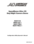
For example, if the dome is installed in a lobby of a busy building, you may want to program
presets that show different areas in the lobby. Figure 12 shows a sample floor plan for the
lobby.
SPEEDDOME ULTRA 8 CONFIGURATION UTILITY
OPERATOR’S GUIDE
8200-0600-01, REV. C
21 of 138
Figure 12. Lobby Floor Plan
Waiting
Area
Security
Office Door
Entry
Dome
Reception
Desk
Hallway
Elevator
If Freeze Frame is disabled, each time the dome points to a different preset, you will see the
dome movement to the new scene, as well as any lens adjustments that are required. For
example, if the dome is currently pointing at Reception Desk, and the preset number assigned
to the Entry is selected, you will see a blur of motion as the dome quickly pans past other areas
in the lobby before focusing on the Entry scene.
If Freeze Frame is enabled, the current scene is displayed on-screen until all dome movement
and lens adjustments are complete. For example, the Reception Desk scene will be frozen
on-screen until the dome completes the movement and lens adjustments necessary to display
the selected preset. When the adjustments are finished, the Entry scene is automatically
displayed.
Changing the Freeze Frame Setting
1. Select Pan/Tilt/Zoom/Sync Opts from the Dome Configuration Menu.
2. Move the highlight bar to Freeze Frame. Change the setting.
• Select On to enable Freeze Frame. This freezes the current scene when presets or
patterns are selected.
• Select Off to disable Freeze Frame. This displays the dome motion and lens adjustments
when presets or patterns are selected.
The default setting is Off.
3. Select Exit. The Dome Configuration Menu appears.
SPEEDDOME ULTRA 8 CONFIGURATION UTILITY
OPERATOR’S GUIDE
8200-0600-01, REV. C
22 of 138
Freeze Frame Performance Notes
The Freeze Frame feature allows the current image to be maintained on-screen when switching
to a preset or pattern. If presets or patterns are included as part of a sequence or tour, the total
movement and lens adjustment time should be included as part of the dwell time to ensure that
the scene will be displayed before moving to the next scene.
Note: This information also applies if you attempt to rapidly call up a series of
presets or patterns without allowing the dome to adjust to the final position for
the preset or pattern.
For example, if it takes 2 seconds for the dome to adjust from displaying Preset 1 to Preset 2,
the 2 second adjustment time should be factored into the sequence/tour dwell time. If the dwell
time is set for 10 seconds, only 8 seconds of live video from the Preset 2 will be seen before
the next event in the sequence is displayed.
The following formula may be useful when calculating actual viewing time for events in a
sequence or tour:
Dwell Time
–
Dome Adjustment Time
=
Actual Viewing Time
Return to Auto After Calling a Preset
When calling a Preset, the SpeedDome Ultra camera adopts the IR Mode and EIS setting
uniquely created for that Preset. When an operator moves the dome from its Preset position,
the dome can return to global IR Mode and EIS settings only if programmed to do so through
the Return to Auto screen.
Follow the steps below to program Return to Auto:
1. Access the Dome Configuration Menu by pressing Iris Open, Focus Far, and Zoom
Out on your controller.
Figure 13. Dome Configuration Menu
DOME CONFIGURATION MENU
PAN/TILT/ZOOM/SYNC OPTS
CAMERA FUNCTIONS
ALARMS/AREAS/HOME/PRESETS/PZ
ON-SCREEN TEXT DISPLAY
LANGUAGE / PASSWORD
DOME INFORMATION
RESET TO FACTORY SETTINGS
QUIT WITHOUT SAVING
EXIT AND SAVE CHANGES
SPEEDDOME ULTRA 8 CONFIGURATION UTILITY
OPERATOR’S GUIDE
8200-0600-01, REV. C
23 of 138
2. Use the joystick to highlight Pan / Tilt / Zoom / Sync Opts, and press Focus Far to
select. The Pan / Tilt / Zoom / Sync Opts screen appears.
Figure 14. Pan/Tilt/Zoom/Sync Options screen
PAN/TILT/ZOOM/SYNC OPTS
PROPORTIONAL FLIP
1ST ZOOM STOP X
MAX TOTAL ZOOM X
LINE LOCK
FREEZE FRAME
RETURN TO AUTO
OFF
35
420
OFF
OFF
RESET TO FACTORY SETTINGS
EXIT
3. Use the joystick to highlight Return to Auto, and press Focus Far to select. The Return
to Auto screen appears.
Figure 15. Return to Auto screen (35X)
RETURN TO AUTO
FOCUS
IRIS
CAMERA FUNCTIONS
ON
ON
ON
RESET TO FACTORY SETTINGS
EXIT
SPEEDDOME ULTRA 8 CONFIGURATION UTILITY
OPERATOR’S GUIDE
8200-0600-01, REV. C
24 of 138
Note: The Camera Functions auto return feature is only available on 35X camera
domes and does not appear on the 22X camera dome Return to Auto screen.
Figure 16. Return to Auto screen (22X)
RETURN TO AUTO
FOCUS
IRIS
ON
ON
RESET TO FACTORY SETTINGS
EXIT
4. Use the joystick to highlight each field (Focus, Iris, and Camera Functions). Select
either On or Off as your global camera default setting for each field.
5. Use the joystick to highlight Exit, and press Focus Far to select. When you reach the
Dome Configuration Menu, highlight Exit and Save Changes, and press Focus Far.
Note: The Reset to Factory Settings field resets only the fields on the Return
To Auto screen.
SPEEDDOME ULTRA 8 CONFIGURATION UTILITY
OPERATOR’S GUIDE
8200-0600-01, REV. C
25 of 138
Chapter 3: Configuring Camera Features
This chapter describes the settings used to control the camera features. It describes how to
change the white balance settings, IR mode, wide dynamic range settings, automatic gain
control (AGC), and open shutter settings to improve camera performance.
Note: The IR mode, WDR, and EIS features are only available on 35X camera
domes. These features do not appear on the 22X camera dome Camera Functions
menu.
When Camera Functions is selected from the Dome Configuration Menu, one of the
following screens appears:
Figure 17. Camera Functions screen (35X)
CAMERA FUNCTIONS
Auto White Bal
ON
IR MODE/nM Auto Mid /Visible
WDR
OFF
AGC/Shutter Max Gain Limit
Open Shutter 26 dB
1/3 s
EIS
OFF
RESET TO FACTORY SETTINGS
EXIT
Figure 18. Camera Functions screen (22X)
CAMERA FUNCTIONS
Auto White Bal
ON
AGC/Shutter Max Gain
Open Shutter 28 dB
Limit
1/3 s
RESET TO FACTORY SETTINGS
EXIT
SPEEDDOME ULTRA 8 CONFIGURATION UTILITY
OPERATOR’S GUIDE
8200-0600-01, REV. C
26 of 138
• To change settings, move the highlight bar to the appropriate field and make the desired
changes.
• To change the settings for this screen to the factory defaults, select Reset to Factory
Settings.
• To return to the Dome Configuration Menu, select Exit.
Adjusting White Balance Settings
White balance is normally compensated for by the automatic white balance gain control. In
some lighting conditions, you may need to manually adjust the red and blue settings for
optimal viewing.
When Automatic White Balance is enabled, the red and blue setting values are based on
feedback from the camera. When Automatic White Balance is disabled, the camera uses the
red and blue setting values to control the white balance. When Automatic White Balance is
first switched from On to Off, the red and blue values displayed are based on the current
feedback from the camera. The red and blue values range from 0 to 511. Changes occur in
increments of 5.
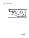
The following chart illustrates the red and blue settings relationship to white balance.
Figure 19. White Balance color relationships
Maximum
Blue
WHITE BALANCE
On-screen Color
appears Magenta
(Purple)
511
Both Red and
Blue settings
are maximized.
On-screen Color
appears Green
0
Minimum
Blue
511 Maximum
Red
Minimum 0
Red
As the value for the red setting increases, the image appears more red. As the value decreases,
the image appears less red.
SPEEDDOME ULTRA 8 CONFIGURATION UTILITY
OPERATOR’S GUIDE
8200-0600-01, REV. C
27 of 138
As the value for the blue setting increases, the image appears more blue. As the value
decreases, the image appears less blue.
As the values for both the red and blue settings are increased, the image appears more magenta
(purple). As the values for both the red and blue settings are decreased, the image appears
more green.
Tip: Auto White Bal must be set to Off to manually change the Red and
Blue settings. Changes to the red and blue settings occur in increments of 5.
Changing Automatic White Balance Settings
1. Select Camera Functions from the Dome Configuration Menu. The highlight appears
on the Auto White Bal setting.
2. Change the setting.
• Select Off to manually adjust the red or blue settings. Continue with step 3.
• Select On for automatic white balance. Continue with step 7.
The default setting is On.
3. Do one of the following:
• To change the red setting, move the highlight bar to W Bal Adj: Red, and then
continue with step 4.
• To change the blue setting, continue with step 5.
4. Adjust the red setting. The values range from 0 to 511 and change in increments of 5.
There is no default value for the red setting.
5. Do one of the following:
• To change the blue setting, move the highlight bar to Blue, then continue with step 6.
• If you are finished making changes, continue with step 7.
6. Adjust the blue setting. The values range from 0 to 511 and change in increments of 5.
There is no default value for the blue setting.
7. Select Exit. The Dome Configuration Menu appears.
Understanding How IR (Black & White) Mode Operates
Note: The IR mode feature is only available on 35X camera domes.
The SpeedDome Ultra 8 camera dome provides a black-and-white (B/W) mode to improve
camera performance when the light level falls below certain thresholds. This allows clear
images to be obtained under low-light conditions. This is referred to as IR Mode. There are
SPEEDDOME ULTRA 8 CONFIGURATION UTILITY
OPERATOR’S GUIDE
8200-0600-01, REV. C
28 of 138
five IR Mode settings: Off, nM On, nM Auto High, nM Auto Mid, and nM Auto Low.
Table 3 lists the approximate lux values when the camera is expected to switch between color
and B/W modes. Actual values depend on the current zoom setting of the camera and the light
source.
Table 3. IR Mode approximate lux parameters
IR Mode
Setting
Camera Performance
B/W Mode
Activates
B/W Mode
Deactivates
Off
No B/W capabilities
N/A
N/A
nM On
Full-time B/W mode
N/A
N/A
nM Auto High
Cleanest possible picture
No field integration effect
~30 lux
~135-155 lux
nM Auto Mid
(Default)
Minimizes field integration
effect
~3 lux
~20-25 lux
nM Auto Low
Maximizes color low-light
performance
~.5 lux
~10-12 lux
For more information, see the following topics:
•
Changing the IR Mode Setting
•
Manually Activating or Deactivating the IR Mode
Changing the IR Mode Setting
1. Select Camera Functions from the Dome Configuration Menu.
2. Move the highlight to the IR Mode field. Change the setting.
• Select OFF to disable the IR mode. The camera will operate in color mode only.
• Select nM ON to enable full-time B/W mode.
• Select nM Auto High to enable automatic B/W mode at approximately 30 lux.
• Select nM Auto Mid to enable automatic B/W mode at approximately 3 lux.
• Select nM Auto Low to enable automatic B/W mode at approximately .5 lux.
The default setting is Auto Mid.
3. Select Exit. The Dome Configuration Menu appears.
Manually Activating or Deactivating the IR Mode
The IR mode may be activated or deactivated using a combination of keyboard commands.
This allows you to change between color and B/W modes as needed.
•
To change the mode using SensorNet or RS-422 protocols: press and hold Iris Open,
press and hold Focus Far, then press Focus Near.
•
To change the mode using Manchester protocol: enter 68, and then press Call Preset.
Using the manual command has the following affect on the menu settings:
SPEEDDOME ULTRA 8 CONFIGURATION UTILITY
OPERATOR’S GUIDE
8200-0600-01, REV. C
29 of 138
Table 4. IR Mode menu settings
If the current IR Mode setting is...
The setting changes to...
IR Mode nM On
IR Mode Off
IR Mode Off
IR Mode nM On
IR Mode nM Auto High, nM Auto Mid, or nM
Auto Low
IR Mode nM On
Tip: If you need to resume nM Auto High, nM Auto Mid, or nM Auto Low IR
mode settings, you must use the Dome Configuration Menu. See Changing the
IR Mode Setting on page 29.
Understanding Wide Dynamic Range
Note: The Wide Dynamic Range feature is only available on 35X camera domes.
Wide Dynamic Range (WDR) is a feature that allows clear viewing of both bright and low
light areas in a scene. Use this feature if you need to view both indoor and outdoor lighting
conditions simultaneously.
For example, a dome is installed in the loading dock area of a building. When the door to the
loading dock area is closed Figure 20, the light level remains constant and the interior scene
can be viewed clearly without iris adjustments.
Figure 20. Example scene of a loading dock with the door closed
When the door is open, additional light from outside enters the room and distortion occurs.
Without WDR, you could adjust the iris of the camera to compensate for the lighting change;
SPEEDDOME ULTRA 8 CONFIGURATION UTILITY
OPERATOR’S GUIDE
8200-0600-01, REV. C
30 of 138
however you cannot clearly see both activities inside and outside of the loading dock area
simultaneously.
For example, if you close the iris, the outside scene will improve, but the interior scene will
become too dark to view clearly. In Figure 21, the car near the loading dock door can be seen
clearly, but the interior of the room appears too dark.
Figure 21. Example scene of loading dock with door open and iris close adjustment
If you want to view the interior scene, open the iris to make the dark scene appear brighter.
However, this causes the outdoor scene to appear too bright. In Figure 22, it is difficult to see
the car near the loading dock door.
Figure 22. Example scene with loading dock door open and iris open adjustment
With WDR enabled, you can see the scenes both inside and outside the loading dock area. In
Figure 23, you can see the boxes stacked inside the loading dock area and the car approaching
the door.
SPEEDDOME ULTRA 8 CONFIGURATION UTILITY
OPERATOR’S GUIDE
8200-0600-01, REV. C
31 of 138
Figure 23. Example scene with loading dock door open and WDR enabled
Note: When WDR is enabled, you might notice a slight flicker to the video
image. This is a normal characteristic of WDR operation.
Changing the Wide Dynamic Range Setting
1. Select Camera Functions from the Dome Configuration Menu.
2. Move the highlight to the WDR field, and then change the setting.
• Select OFF to disable WDR. Use this setting when the light level is constant or changes
in lighting conditions are gradual.
• Select ON to enable WDR. Use this setting when both bright- and low-light areas need
to be viewed simultaneously.
The default setting is OFF.
3. Select Exit. The Dome Configuration Menu appears.
Note: When Electronic Image Stabilization (EIS) is enabled, the Wide Dynamic
Range feature cannot be enabled and does not display on the Camera Functions
screen.
Working with AGC and Open Shutter Settings
The SpeedDome Ultra 8 camera dome provides settings for compensating for low-light scenes
in color: Automatic Gain Control and Open Shutter. Automatic Gain Control (AGC) amplifies
the video signal in scenes with minimal light. Many low-light scenes result in picture noise. As
gain is increased, the picture noise is also amplified.
SPEEDDOME ULTRA 8 CONFIGURATION UTILITY
OPERATOR’S GUIDE
8200-0600-01, REV. C
32 of 138
When AGC is enabled, the camera automatically adjusts the gain setting value. When AGC is
disabled, no gain is applied to the video signal. This may make the video appear darker on the
monitor.
The gain setting for the camera differs from the maximum gain (Max Gain) setting available
on the Camera Functions menu. The Max Gain setting is an upper limit for how much gain
can be increased when AGC is enabled. The trade-off between picture level (brightness) and
noise may be adjusted by setting the Max Gain value. Lower values for Max Gain setting
may result in a darker picture with less noise. Higher values for Max Gain setting may result
in a brighter picture with more noise.
In addition to the AGC settings, you may also adjust the Open Shutter settings to improve
dome performance in low light situations.
Understanding How Advanced Shutter Settings Improve Low-Light Performance
The camera dome supports the ability to view color images from extremely low-light
situations. This feature is called Open Shutter and is only in effect during low-light situations
where an image would not be obtainable otherwise. It does not affect the camera performance
in normal or bright light situations.
When the Open Shutter is enabled and the scene illumination is too low to obtain a clear image
at the normal video rate, the camera collects luminance information from multiple fields. As it
does so, the current video information is retransmitted until new information is available from
the camera. Under these conditions, moving objects will appear blurred, and still images may
appear blurred, choppy, and with more static than video obtained under normal lighting
conditions.
The Shutter Limit value sets the video update time in fractions of a second. Depending on the
lighting conditions, the video information may be updated more frequently, but no slower than
the limit set.
Figure 24 illustrates a Shutter Limit of 1/4.
Figure 24. Graphical view of Shutter Limit settings
250
msec
250
msec
180
msec
In this example, the dome receives information about the color of the traffic light. While the
light is red, the image is relatively static. With the shutter limit set to 1/4 second
(250 milliseconds), updated red light information is transmitted at 1/4-second intervals. When
the light changes from red to green, updated light color information becomes available. The
dome must now transmit information about the green light. This update occurs as soon as the
green light information is available. This may occur before the 1/4-second interval elapses. In
this example, the light changed to green after 180 milliseconds. Thereafter the green light
information is transmitted at 1/4-second intervals until new light color information becomes
available.
If the light were to change from red to green halfway through the field integration interval
(125 milliseconds), it may appear that both the red and green lights are on simultaneously. This
situation is illustrated in Figure 25.
SPEEDDOME ULTRA 8 CONFIGURATION UTILITY
OPERATOR’S GUIDE
8200-0600-01, REV. C
33 of 138
Figure 25. Mixed field integration
Red Light
Red Light
Red/Green Light
250
msec
125
msec
Green Light
125
msec
Adjusting the Shutter Limit sets the update time used to maintain the image quality. If you
want to videotape an incident in low-light conditions, you may find that tape quality is not
acceptable. To ensure that the videotape quality is acceptable for possible prosecution
purposes, you may want to test the Shutter Limit settings under the expected lighting
conditions.
The Relationship between AGC and Open Shutter Settings
The following table shows which settings can be changed based on the current AGC/Shutter
setting.
Table 5. AGC and Open Shutter Relationships
AGC/Shutter Setting
Max Gain
Limit
AGC Off
N/A
N/A
AGC On
NTSC: 10–32dB (35X camera)
NTSC: 0–28dB (22X camera)
PAL: 0–29dB (both 35X and 22X)
N/A
Open Shutter
NTSC: 10–32dB (35X camera)
NTSC: 0–28dB (22X camera)
PAL: 0–29dB (both 35X and 22X)
NTSC: 1/2–1/60
PAL: 2/3–1/50
Configuring AGC and Open Shutter Settings
1. Select Camera Functions from the Dome Configuration Menu.
2. Move the highlight to AGC/Shutter mode field. The highlight appears in the first field
(AGC/ Mode).
3. Select one of the following:
• Select AGC On to set AGC to automatic mode. This allows you to adjust the maximum
AGC gain setting (in decibels). Continue with step 4.
• Select AGC Off to set the AGC to minimum level. You cannot adjust the maximum
AGC gain or shutter limit settings. Continue with step 7.
• Select Open Shutter to enable field integration. This allows you to adjust the
maximum AGC gain and shutter limit settings. Continue with step 4.
The default setting is Open Shutter.
4. Move the highlight to Max Gain field. Change the setting. The following settings are
available:
• For 22X cameras, the setting values range from 0 to 28dB.
• For 35X cameras, the setting values range from 10 to 32dB.
SPEEDDOME ULTRA 8 CONFIGURATION UTILITY
OPERATOR’S GUIDE
8200-0600-01, REV. C
34 of 138
5. If you have selected Open Shutter and need to change the shutter limit setting, continue
below. Otherwise, continue with step 7.
6. Move the highlight to the Limit field. Change the setting. The following settings are
available:
• For NTSC cameras, the setting values range from 1/2 to 1/60.
• For PAL cameras, the setting values range from 2/3 to 1/50.
The default setting is 1/4 for NTSC and 1/3 for PAL.
7. Select Exit. The Dome Configuration Menu appears.
Setting Up Electronic Image Stabilization (EIS)
Note: The EIS feature is only available on 35X camera domes.
You can turn off EIS or adjust the EIS sensitivity level for 35X cameras on your system
through the Camera Functions screen.
Follow the steps below:
1. Access the Dome Configuration Menu (Figure 26) by pressing Iris Open, Focus Far,
and Zoom Out on your controller.
Figure 26. Dome Configuration Menu
DOME CONFIGURATION MENU
PAN/TILT/ZOOM/SYNC OPTS
CAMERA FUNCTIONS
ALARMS/AREAS/HOME/PRESETS/PZ
ON-SCREEN TEXT DISPLAY
LANGUAGE / PASSWORD
DOME INFORMATION
RESET TO FACTORY SETTINGS
QUIT WITHOUT SAVING
EXIT AND SAVE CHANGES
2. Use the joystick to highlight Camera Functions and press Focus Far to select. The
Camera Functions screen (Figure 27) appears.
SPEEDDOME ULTRA 8 CONFIGURATION UTILITY
OPERATOR’S GUIDE
8200-0600-01, REV. C
35 of 138
Figure 27. Camera Functions screen
CAMERA FUNCTIONS
Auto White Bal
ON
IR MODE/nM Auto Mid /Visible
WDR
OFF
AGC/Shutter Max Gain Limit
Open Shutter 26 dB
1/3 s
EIS
OFF
RESET TO FACTORY SETTINGS
EXIT
3. Make your desired changes. EIS settings provide the following choices:
• 10 Hz = Default setting designed to stabilize the dome when unwanted dome
movements are at 10 Hz.
• 5 Hz = Designed to stabilize the dome when unwanted dome movements are at 5 Hz.
• Off = Turns off Electronic Image Stabilization.
Note: When EIS is enabled, the WDR feature cannot be enabled and does not
appear on the Camera Functions screen.
SPEEDDOME ULTRA 8 CONFIGURATION UTILITY
OPERATOR’S GUIDE
8200-0600-01, REV. C
36 of 138
Chapter 4: Configuring Alarms, Areas, Home, Privacy Settings,
Presets and Scan Limits
This chapter describes settings associated with Alarms, Areas, the Home Position, Privacy
Zones, Presets and Scan Limits. It explains how to set a default action to run when a dome
alarm occurs, as well as how to define the normal alarm input states. It describes how to set a
default position for the dome and assign a dome position that corresponds with North. It also
explains how to program Areas, Privacy Zones, Presets and Scan Limits.
When Alarms/Areas/Home/Presets/PZ is selected from the Dome Configuration Menu,
the following screen appears:
Figure 28. Alarms/Areas/Home/Presets/PZ screen
ALARMS/AREAS/HOME/PRESETS/PZ
SET ALARM ACTIONS
SET ALARM STATES
SET HOME POSITION
SET NORTH POSITION
AREA BOUNDARIES
PRIVACY ZONES
PRESETS
SCAN LIMITS
EXIT
From this menu you can choose to configure alarm actions, configure normal states for alarm
inputs, assign the “home position,” establish the north position for the dome, set area
boundaries, set privacy zones, and program presets.
• To make changes, select a menu item to display the associated settings.
• To change the settings, move the highlight bar to appropriate field and make the changes.
• To return to the Dome Configuration Menu, select Exit.
SPEEDDOME ULTRA 8 CONFIGURATION UTILITY
OPERATOR’S GUIDE
8200-0600-01, REV. C
37 of 138
Configuring Alarm Actions
IMPORTANT
When operating on Manchester networks, the dome can be programmed to respond
to any of the four available alarm inputs. However, the dome cannot transmit alarm
input states to the host controller. If transmitting the alarm state to the host controller
is required, the alarm device must be wired directly to the host controller.
The dome provides four alarm inputs. By connecting alarm devices, such as smoke alarms,
twilight sensors, or motion sensors, to these inputs, you can enhance the usability of your
video surveillance system. You can further improve your video surveillance by assigning a
dome action, such as a preset or pattern, to start whenever an alarm input changes from normal
to abnormal.
When Set Alarm Actions is selected from Alarms/Areas/Home/Presets/PZ screen, the
following screen appears:
Figure 29. Set Alarm Actions screen
SET ALARM ACTIONS
INPUT
1
2
3
4
NO
NO
NO
NO
ACTION
ACTION
ACTION
ACTION
ACTION
SEND INPUTS TO HOST? YES
EXIT
Use this screen to assign a preset or pattern to occur whenever the alarm's input state changes
from normal to abnormal. You may also choose to have no action occur when the alarm's input
state changes.
Alarms can be processed internally by the dome, externally by the controller, or both. You
may choose to send changes in the input state to the host controller. If the changes in input
state are sent to the host controller, the host actions have higher priority than the associated
dome actions.
Note: An active internal alarm only resets when the input state changes to
“normal.” A manual reset is not available.
SPEEDDOME ULTRA 8 CONFIGURATION UTILITY
OPERATOR’S GUIDE
8200-0600-01, REV. C
38 of 138
Setting Alarm Actions
IMPORTANT
Some controllers allow the alarm actions for domes to be specified at the controller.
See the appendixes for information about which controllers support this function. Do
not use both the dome configuration utility and the controller to assign the alarm
actions for the same input.
Use only the dome configuration utility or the controller to the assign the alarm
actions.
1. Select Alarms/Areas/Home/Presets/PZ from the Dome Configuration Menu.
2. Select Set Alarm Actions.
The Set Alarm Action screen appears.
3. Move the highlight bar to the appropriate alarm input. Change the setting.
• Select from the following alarm actions: Preset, Pattern, Output, Sequence,
Random Scan, Stepped Scan, or Smooth Scan.
• Select No Action if you do not want to set an alarm action. Continue with step 6.
The default setting is No Action.
4. Move the highlight bar to the Action field and select the action number.
• For preset, select the number from 1 through 96. Continue with step 5.
Note: The protocol (or controller) used may support fewer presets. Refer to
the appropriate Appendix for additional information.
• For pattern, select the number from 1 through 3 for the pattern you want to assign.
Continue with step 5.
If the selected pattern is not programmed, the dome runs the Apple Peel pattern.
• For output, select the number from 1 through 3 for the output you want to assign.
Continue with step 5.
• For sequence, select the number from 1 through 16 for the sequence you want to
assign. Continue with step 5.
• For random scan, stepped scan, and smooth scan, continue with step 5.
5. If you need to make additional changes to the alarm actions for this dome, repeat steps 3
and 4. When finished, continue with step 6.
6. Move the highlight bar to Send Inputs to Host?
• Choose Yes to forward changes in input states to the host controller.
• Choose No to prevent changes in the input states from being forwarded to the host
controller.
The default setting is Yes.
7. Select Exit to return to the Alarm/Areas/Home/PZ screen.
SPEEDDOME ULTRA 8 CONFIGURATION UTILITY
OPERATOR’S GUIDE
8200-0600-01, REV. C
39 of 138
8. When the Alarm/Areas/Home/PZ screen appears, select Exit. The Dome Configuration
Menu appears.
Configuring Normal Input States for Alarms
IMPORTANT
Some controllers allow the normal input states for domes to be specified at the
controller. These controllers include VM96, AD matrices with AD2083-02A code
units or AD168 matrix with the AD168CCM or AD2083-02A code unit. Do not use
both the dome configuration utility and the controller to assign the normal input
states. Use only the dome configuration utility or the controller to assign the
normal input states.
The normal input state for an alarm is the state that the device maintains when an alarm is not
occurring. For example, you have a smoke detector connected to a dome input. Under normal
circumstances, the smoke detector should not be detecting smoke. When smoke is detected, the
alarm input changes states (from open to closed) and an alarm is issued.
To configure the normal state for the alarm, select Set Alarm States from the
Alarm/Areas/Home/Presets/PZ screen. The following screen appears:
Figure 30. Set Alarm States screen
SET ALARM STATES
INTERNAL ALARMS
INPUT
NORMAL STATE
1
2
3
4
OPEN
OPEN
OPEN
OPEN
EXIT
Use this screen to assign open or closed as the normal state for the dome alarm inputs. When
an input state changes from normal to abnormal and an internal alarm action is associated with
the input, the alarm is triggered. The normal state is used by both internal alarms and controller
defined alarms.
SPEEDDOME ULTRA 8 CONFIGURATION UTILITY
OPERATOR’S GUIDE
8200-0600-01, REV. C
40 of 138
IMPORTANT
When operating on Manchester networks, the dome can be programmed to respond
to any of the four available alarm inputs. However, the alarm input states cannot be
transmitted to the host controller. If transmitting the alarm input state to the host
controller is required, the alarm device must be wired directly to the host controller.
Setting Alarm Input States
1. Select Alarms/Areas/Home/Presets/PZ from the Dome Configuration Menu.
2. Select Set Alarm States.
3. Select the appropriate input line, and then change the setting.
• Select Open if the alarm normal input state is open.
• Select Closed if the alarm normal input state is closed.
The default setting is Open.
Note: In most cases, the normal input state for a dome's input should match the
contact type of the connected switch.
4. Repeat step 3 for each input requiring change. When finished, continue with step 5.
5. Select Exit to return to the Alarms/Areas/Home/Presets/PZ screen.
6. When the Alarms/Areas/Home/Presets/PZ screen appears, select Exit. The Dome
Configuration Menu appears.
Assigning the Dome’s Home Position
The home position is a preset or pattern that automatically runs after a designated period of
dome inactivity. Use this option if you want to keep a specific area to be under surveillance
whenever the dome is not moving.
To assign the home position, select Set Home Position from the
Alarms/Areas/Home/Presets/PZ screen. The following screen (Figure 31) appears:
SPEEDDOME ULTRA 8 CONFIGURATION UTILITY
OPERATOR’S GUIDE
8200-0600-01, REV. C
41 of 138
Figure 31. Set Home Position screen
SET HOME POSITION
ACTION
PRESET
RETURN TIME MINS
1
10
EXIT
Tip: When a pattern is selected as the home position, the pattern runs until stopped
manually by issuing a camera command, such as Tilt or Focus.
Setting the Home Position
1. Select Alarms/Areas/Home/Presets/PZ from the Dome Configuration Menu.
2. Select Set Home Position.
The highlight bar appears on the Home Position setting.
3. Select a setting.
• Select from the following home positions: Preset, Pattern, Output, Sequence,
Random Scan, Stepped Scan, or Smooth Scan.
Refer to Understanding Scan Limits on page 64 for additional details.
• Select No Action if you do not want to set a home position. Continue with step 5.
The default setting is No Action.
4. Move the highlight bar to the Number field, and select a number.
• For preset, select the number from 1 through 96. Continue with step 5.
Note: The protocol used may support fewer presets. Refer to the
appropriate Appendix for additional information.
• For pattern, select the number from 1 through 3 for the pattern you want to assign.
Continue with step 5.
SPEEDDOME ULTRA 8 CONFIGURATION UTILITY
OPERATOR’S GUIDE
8200-0600-01, REV. C
42 of 138
If the selected pattern is not programmed, the dome runs the Apple Peel pattern.
• For output, select the number from 1 through 3 for the output you want to assign.
Continue with step 5.
• For sequence, select the number from 1 through 16 for the sequence you want to
assign. Continue with step 5.
• For random scan, stepped scan, and smooth scan, continue with step 5.
5. Move the highlight bar to Return Time Mins. Set the amount of time that the dome must
remain inactive before returning to the home position.
• The setting ranges from 1 to 60 minutes.
The default setting is 10 minutes.
6. Select Exit to return to the Alarms/Areas/Home/Presets/PZ screen.
Note: If you selected a preset that has not been programmed, preset programming
automatically starts. See Changing Camera Functions and Motion Detection
Setup within Presets on page 59.
7. When the Alarms/Areas/Home/Presets/PZ screen appears, select Exit. The Dome
Configuration Menu appears.
Setting the North Position
Direction Indicators permit you to understand the approximate pointing position of the dome
to an established reference point. This reference point is called “North” and may correspond to
magnetic north (if it is known) or some other landmark or fixture. When the dome is initially
installed, “North” defaults to a pre-defined position (0° pan/tilt). You may program the
“North” position to be any point along the dome's pan axis (also called azimuth).
For more information about Direction Indicators, see Chapter 5: Configuring Text Displayed
On-Screen.
Programming the North Position
1. Select Alarms/Areas/Home/Presets/PZ from the Dome Configuration Menu.
2. Select Set North Position.
The following screen (Figure 32) appears:
SPEEDDOME ULTRA 8 CONFIGURATION UTILITY
OPERATOR’S GUIDE
8200-0600-01, REV. C
43 of 138
Figure 32. Set North Position screen
SET NORTH POSITION
PAN to new north position
ZOOM to mark north position
FOCUS quits w/o changing
3. Point the dome to the new North position. When satisfied with the view, save the setting,
or cancel the change.
4. The Alarms/Areas/Home/Presets/PZ screen appears. Select Exit. The Dome
Configuration Menu appears.
Programming Area Boundaries
If the dome is installed in a location where you can see numerous departments or other
identifiable objects, you might want to consider programming area boundaries. Areas are
programmed start- and end-points of a camera's field of view. Each area is a part of a circular
viewing area that extends around the dome.
For example, Figure 33 represents the floor plan of a break room. The room includes a main
entrance, tables with chairs, vending machines, lockers, and an emergency exit. Areas have
been programmed around the fixtures in the room. As shown in this example, areas can be
different sizes.
SPEEDDOME ULTRA 8 CONFIGURATION UTILITY
OPERATOR’S GUIDE
8200-0600-01, REV. C
44 of 138
Figure 33. An example of areas found in a break room
Entrance
Start of Area 1/
End of Area 8
Emergency
Exit
Vending Machines
Area
1
Area
8
Areas appear smaller
when zoomed in.
Lockers
Area
7
Area
2
Dome
Area
6
Area
5
Area
3
Area
4
Areas appear larger when
zoomed out.
The ending point of one area is the starting point for the next area. The ending point of the last
area cannot go past the starting point of the first area. In this example, the area that includes
the vending machines cannot extend past the starting point of the area that includes the
emergency exit. If your controller supports areas, these are separate from the areas you can
program with the dome. You should not use both the controller and the configuration utility to
define areas.
The zoom level also affects how large areas appear. When you zoom in to an area, the area
may appear to be small. When you pan the dome, area boundaries may appear to be close.
However, if you zoom out, the area appears to be larger. When you pan the dome, the area
boundaries appear further apart. With this in mind, it will be easier to establish area boundaries
if the zoom level is small than if the zoom level is large.
Note: When areas are programmed, each area is assigned a default name.
Instructions for assigning new names appear in Chapter 5: Configuring Text
Displayed On-Screen on page 71.
SPEEDDOME ULTRA 8 CONFIGURATION UTILITY
OPERATOR’S GUIDE
8200-0600-01, REV. C
45 of 138
To program areas, select Area Boundaries from the Alarms/Areas/Home/Presets/PZ
screen. The following screen appears:
Figure 34. Area Boundaries screen
AREA BOUNDARIES
PAN to START OF BOUND
1
PAN RIGHT ONLY
ZOOM to mark BOUNDARY
FOCUS quits w/o changing
If no boundary is set, pressing Focus quits without making any changes.
The dome supports from 2 to 16 areas.
IMPORTANT
If areas were previously programmed, you cannot restore the previously
programmed boundaries by selecting Quit Without Saving from the Dome
Configuration Menu once you begin making changes to the boundaries.
Setting Area Boundaries
1. Select Alarms/Areas/Home/Presets/PZ from the Dome Configuration Menu.
2. Move the highlight bar to Area Boundaries, then select.
The Area Boundaries screen appears.
3. Adjust the camera to the starting point of the first area, and press Zoom to mark the
boundary.
4. Adjust the dome to the right until the ending point of the area is seen. If you attempt to
move left, an error message appears. See the note on page 47 for information.
2
5. Mark the end-point of the area.
The area number automatically advances.
6. Repeat steps 4 and 5 for each area you want to establish.
SPEEDDOME ULTRA 8 CONFIGURATION UTILITY
OPERATOR’S GUIDE
8200-0600-01, REV. C
46 of 138
Note: You will receive an error message under the following conditions:
• If you attempt to program an area boundary that passes the starting point of
the first area
• If you move the camera left after establishing the first boundary
Return to step 2 and start again.
7. When the last area boundary is set, save the changes. A message appears confirming that
the areas have been successfully saved. Press Focus to continue.
8. When the Alarms/Areas/Home/Presets/PZ screen appears, select Exit. The Dome
Configuration Menu appears.
Establishing Privacy Zones
Privacy Zones are “masked” sections of the dome’s viewing area. These masks prevent
operators of the surveillance system who do not have access to the dome password from
viewing these designated zones. Each zone has four sides, and the zones may overlap to form
irregular shapes. The Privacy Zones move in relation to the dome pan/tilt position. In addition,
the apparent size of the Privacy Zone adjusts automatically as the zoom level is adjusted. Up to
eight Privacy Zones may be established for a dome.
Privacy Zones are useful for high security areas. For example, you might establish a Privacy
Zone around a safe’s combination. However, you could view people approaching or opening
the safe.
When Privacy Zones are active, the dome's firmware automatically disables text transparency.
For additional information about text appearance, see Chapter 5: Configuring Text Displayed
On-Screen on page 71.
In addition, the appearance of the configuration menus changes slightly when Privacy Zones
are active. Both the first and last lines of the menus will appear in enlarged text when Privacy
Zones are active. The menus change to one-sized text if Privacy Zones are hidden or deleted.
To program Privacy Zones, select Privacy Zones from the Alarms/Areas/Home/Presets/
PZ screen. The following screen (Figure 35) appears:
SPEEDDOME ULTRA 8 CONFIGURATION UTILITY
OPERATOR’S GUIDE
8200-0600-01, REV. C
47 of 138
Figure 35. Privacy Zones screen
PRIVACY ZONES
ADD PRIVACY ZONE
DELETE SPECIFIC ZONES
DELETE ALL ZONES
HIDE ALL ZONES NO
EXIT
From this screen, you can program up to eight Privacy Zones, delete all or specific Privacy
Zones, or temporarily hide all Privacy Zones.
How Privacy Zones are Programmed
Privacy Zones are established by selecting three points on the display image to mask. The
fourth point on the Privacy Zone is automatically generated by mirroring the longest axis
between the three selected points. Figure 36 illustrates how Privacy Zones are programmed.
Figure 36. Privacy Zone programming example
Point 1 +
Point 2 +
+ Point 4 mirrors
the longest axis.
+
Point 3
The dome’s firmware prevents you from establishing a zone that is too small or too large
(greater than 90-degrees pan or tilt from the starting point).
Figure 37 illustrates the Privacy Zone programming screen:
SPEEDDOME ULTRA 8 CONFIGURATION UTILITY
OPERATOR’S GUIDE
8200-0600-01, REV. C
48 of 138
Figure 37. Privacy Zone Programming screen
NEW PRIVACY ZONE
Navigate
corner
1
ZOOM to mark corner
FOCUS to abandon zone
The circled arrows represent the target area on the screen for creating the Privacy Zone.
Normally, this target area remains in the center of the screen. Using the Pan/Tilt control
moves the target area by panning or tilting the dome. If the dome reaches its maximum tilt
position, the Privacy Zone may still be established in the upper part of the display. When this
occurs, the arrows move relative to the movement of the Pan/Tilt control until the top of the
display area is reached.
The boundary points on the Privacy Zone are selected by pressing Zoom. Once a boundary
point is selected, the arrows “blink” until the target area is moved to a valid area. Once the
target moves to a valid area, the arrows stop blinking. If you move the target more than 90degrees from a selected point, the arrows begin to blink again, indicating that the boundary is
too large.
If you attempt to establish a boundary point while the arrows are blinking you will receive an
error message: Zone is Too Small or Zone is Too Large. If this happens, you must start
programming from the beginning. Pressing Focus Far returns you to the Privacy Zone
programming screen.
If you attempt to program more than eight Privacy Zones, the following message appears:
Maximum Allowed Number of Zones Defined
Pressing Focus Far returns to the Program Privacy Zones screen. To program a new zone,
you must delete at least one of the eight existing Privacy Zones. See Removing or Hiding
Privacy Zones on page 50.
IMPORTANT
Areas of the Privacy Zone may be exposed during rapid pan / tilt movements of the
dome. To compensate for this limitation, you may want to program the Privacy
Zone to be 20 to 25% larger than the area you want to mask.
SPEEDDOME ULTRA 8 CONFIGURATION UTILITY
OPERATOR’S GUIDE
8200-0600-01, REV. C
49 of 138
Programming Privacy Zones
1. Select Alarms/Areas/Home/Presets/PZ from the Dome Configuration Menu.
2. Select Privacy Zones.
3. The Program Privacy Zones screen appears. Select Add Privacy Zone.
4. Use the Pan/Tilt control to position the arrows over the boundary point. Press Zoom to
create.
5. Repeat step 4 to create boundary points 2 and 3.
Tip: Remember, if the arrows are blinking, you are not in a valid target area.
Only select a point if the arrows are not blinking.
6. After the third boundary point is created, the fourth boundary point is automatically
calculated. The new Privacy Zone appears on the screen. To program additional Privacy
Zones, repeat steps 3 through 5. When finished, continue with step 7.
7. Select Exit to return to Alarms/Areas/Home/Presets/PZ screen.
8. When the Alarms/Areas/Home/Presets/PZ screen appears, select Exit. The Dome
Configuration Menu appears.
Removing or Hiding Privacy Zones
If you make an error during programming or no longer require Privacy Zones, individual zones
or all Privacy Zones may be deleted. To temporarily remove the Privacy Zones, you may
disable their appearance by changing the Hide All Zones setting to Yes.
To delete individual Privacy Zones, you must adjust the position of the arrows to the area of
the screen where the zone is recognized by the firmware. If multiple Privacy Zones are close
together or overlap, the arrows blink, indicating that the selection is not allowed. Figure 38
illustrates Privacy Zones that are close together.
Figure 38. Deleting Privacy Zones – Invalid Selection
Zone 2
Zone 1
Navigate
zone
Zone 3
ZOOM to delete zone
FOCUS quits w/o changing
Arrows blink to
indicate this is an
invalid selection.
Three Privacy Zones are illustrated. Zones 1 and 2 are overlapping. Zone 1 and 3 are in close
proximity. In this situation, the arrows blink because the target area is the same distance from
all three zones.
SPEEDDOME ULTRA 8 CONFIGURATION UTILITY
OPERATOR’S GUIDE
8200-0600-01, REV. C
50 of 138
To ensure that the correct Privacy Zone is deleted, place the arrows clearly in the zone you
want to delete. Figure 39 illustrates a valid selection.
Figure 39. Deleting Privacy Zone – Valid Selection
Zone 2
Zone 1
Navigate
zone
Zone 3
ZOOM to delete zone
FOCUS quits w/o changing
Arrows stop blinking
indicating this is a
valid selection.
By moving to the left, the arrows stop blinking when the target area enters Zone 1. Pressing
Zoom allows you to delete Zone 1. If you do not want to delete the zone, press Focus
Note: Once you delete a zone, pressing Focus saves and exits the Delete
Privacy Zones screen.
Deleting Specific Privacy Zones
To delete individual Privacy Zones, use the following procedure. To delete all Privacy Zones,
see Deleting All Privacy Zones.
1. Select Alarms/Areas/Home/Presets/PZ from the Dome Configuration Menu.
2. Select Privacy Zones.
The Program Privacy Zones screen displays.
3. Select Delete Specific Zones.
4. Position the arrows in the Privacy Zone that you want to delete. Press Zoom to delete. If
you do not want to delete the zone, press Focus.
5. Repeat steps 3 and 4 for each Privacy Zone you want to delete. When finished, select Exit.
6. When the Alarms/Areas/Home/Presets/PZ screen appears, select Exit. The Dome
Configuration Menu appears.
Deleting All Privacy Zones
To delete all Privacy Zones, use the following procedure. To delete individual Privacy Zones,
see Deleting Specific Privacy Zones.
1. Select Alarms/Areas/Home/Presets/PZ from the Dome Configuration Menu.
2. Select Privacy Zones. The Program Privacy Zones screen displays.
3. Select Delete All Zones.
SPEEDDOME ULTRA 8 CONFIGURATION UTILITY
OPERATOR’S GUIDE
8200-0600-01, REV. C
51 of 138
4. The following prompt appears:
YOU ARE ABOUT TO DELETE
ALL PRIVACY ZONES
CANCEL
CONTINUE
5. To delete all Privacy Zones, select Continue.
If you do not want to delete all Privacy Zones, select Cancel. The Program Privacy
Zones screen displays.
6. Select Exit to return to Alarms/Areas/Home/Presets/PZ screen.
7. When the Alarms/Areas/Home/Presets/PZ screen appears, select Exit. The Dome
Configuration Menu appears.
Hiding Privacy Zones
If you want to temporarily disable the appearance of Privacy Zones, you may “hide” them.
This allows you to keep the Privacy Zones that have been programmed while disabling their
appearance on-screen.
To hide all Privacy Zones:
1. Select Alarms/Areas/Home/Presets/PZ from the Dome Configuration Menu.
2. Select Privacy Zones.
The Program Privacy Zones screen displays.
3. Select Hide All Zones. Change the setting.
• Select Yes to hide all Privacy Zones.
• Select No to make all Privacy Zones active.
The default setting is No.
4. Select Exit to return to Alarms/Areas/Home/Presets/PZ screen.
5. When the Alarms/Areas/Home/Presets/PZ screen appears, select Exit. The Dome
Configuration Menu appears.
Programming Sequences
A Sequence is a sequential display of multiple camera Presets. Sequences provide a methodical
and effective way to monitor multiple areas of interest by switching to different Presets
automatically. Sequences are programmed from the Select Preset to Program screen.
Sequences are created by identifying Preset views to include in the Sequence and specifying a
dwell time that controls how long each Preset remains on-screen before switching to another
Preset. Up to 16 Sequences can be created, each with 16 steps (Presets).
Steps to Programming Sequences
Follow the steps below to program Sequences.
1. Access the Dome Configuration Menu (Figure 40) by pressing Iris Open, Focus Far,
and Zoom Out on your controller.
SPEEDDOME ULTRA 8 CONFIGURATION UTILITY
OPERATOR’S GUIDE
8200-0600-01, REV. C
52 of 138
Figure 40. Dome Configuration Menu screen
DOME CONFIGURATION MENU
PAN/TILT/ZOOM/SYNC OPTS
CAMERA FUNCTIONS
ALARMS/AREAS/HOME/PRESETS/PZ
ON-SCREEN TEXT DISPLAY
LANGUAGE / PASSWORD
DOME INFORMATION
RESET TO FACTORY SETTINGS
QUIT WITHOUT SAVING
EXIT AND SAVE CHANGES
2. Highlight Alarms / Areas / Home / Presets / PZ and press Focus Far to select. The
Alarms/Areas/Home/Presets/PZ screen appears.
Figure 41. Alarms/Areas/Home/Presets/PZ screen
ALARMS/AREAS/HOME/PRESETS/PZ
SET ALARM ACTIONS
SET ALARM STATES
SET HOME POSITION
SET NORTH POSITION
AREA BOUNDARIES
PRIVACY ZONES
PRESETS
SCAN LIMITS
EXIT
3. Highlight Presets and press Focus Far. The Select Preset To Program screen
(Figure 42) appears.
SPEEDDOME ULTRA 8 CONFIGURATION UTILITY
OPERATOR’S GUIDE
8200-0600-01, REV. C
53 of 138
Figure 42. Select Preset to Program screen
SELECT PRESET TO PROGRAM
PRESET
NUMBER
1
PRESET NAME
PRESET
1
MOTION DETECTION SETUP
SEQUENCE SETUP MENU
CAMERA FUNCTIONS
FOCUS FAR to program preset
EXIT
4. Highlight Sequence Setup Menu and press Focus Far. The Sequence Setup Menu
screen appears.
Figure 43. Sequence Setup Menu screen
SEQUENCE SETUP MENU
SEQUENCE NUMBER
1
STEP 1-4
DWELL TIME
STEP PRESET
MIN / SEC
1
0
0
0
2
0
0
0
3
0
0
0
4
0
0
0
EXIT
5. Highlight the Sequence Number field. Press Zoom In/Out to change values (1-16).
6. Highlight the Step field. Press Zoom In/Out to scroll through available steps. Steps are
displayed in groups of 1-4, 5-8, 9-12, and 13-16.
7. Highlight the Preset field and press Zoom In/Out until the desired Preset number
appears (1-96).
8. Highlight the Dwell Time Min field and press Zoom In/Out until the number of minutes
you want the Preset to remain on-screen appears (0-10 minutes).
9. Highlight the Dwell Time Sec field and press Zoom In/Out until the number of seconds
you want the Preset to remain on-screen appears (0-60 seconds in 10-second increments).
SPEEDDOME ULTRA 8 CONFIGURATION UTILITY
OPERATOR’S GUIDE
8200-0600-01, REV. C
54 of 138
10. Repeat steps 7 through 9 above until the first 4 presets have been programmed. If more
Presets are desired, highlight the Step field and use Zoom In/Out to display sequence
steps 5-8.
11. When finished, highlight Exit and press Focus Far to select.
12. At the Dome Configuration Menu screen, highlight Exit and Save Changes and
press Focus Far to save.
Running Sequences 1-16
Two options are available for running Sequences:
•
Option 1 – If your keyboard supports the DirectSet command, you can use it to run a
Sequence immediately (see Accessing the DirectSet Menu on page 12). Consult your
keyboard manual for information on DirectSet functions.
•
Option 2 - Use the Set Home Position method to schedule one Sequence to run when the
dome returns to its home position (after a defined period of inactivity).
Follow the steps below to run Sequences from the Set Home Position screen:
1. Access the Dome Configuration Menu (Figure 44) by pressing Iris Open, Focus Far,
and Zoom Out on your controller.
Figure 44. Dome Configuration Menu screen
DOME CONFIGURATION MENU
PAN/TILT/ZOOM/SYNC OPTS
CAMERA FUNCTIONS
ALARMS/AREAS/HOME/PRESETS/PZ
ON-SCREEN TEXT DISPLAY
LANGUAGE / PASSWORD
DOME INFORMATION
RESET TO FACTORY SETTINGS
QUIT WITHOUT SAVING
EXIT AND SAVE CHANGES
2. Highlight Alarms / Areas / Home / Presets / PZ and press Focus Far to select. The
Alarms/Areas/Home/Presets/PZ screen (Figure 45) appears.
SPEEDDOME ULTRA 8 CONFIGURATION UTILITY
OPERATOR’S GUIDE
8200-0600-01, REV. C
55 of 138
Figure 45. Alarms/Areas/Home/Presets/PZ screen
ALARMS/AREAS/HOME/PRESETS/PZ
SET ALARM ACTIONS
SET ALARM STATES
SET HOME POSITION
SET NORTH POSITION
AREA BOUNDARIES
PRIVACY ZONES
PRESETS
SCAN LIMITS
EXIT
3. Highlight Set Home Position and press Focus Far. The Set Home Position screen
appears.
Figure 46. Set Home Position screen
SET HOME POSITION
ACTION
PRESET
RETURN TIME MINS
1
10
EXIT
4. On the highlighted Action field, press Zoom In/Out until Sequence appears.
5. Highlight the number field. Press Zoom In/Out until your desired Sequence number
appears.
6. Highlight the Return Time Mins field. Press Zoom In/Out to specify when the dome is
to return to its home position after a period of inactivity (1-60 min.). This triggers the
Sequence to run.
7. Highlight the Exit field and press Focus Far to select.
8. Continue to exit until the completely out of all programming menus.
SPEEDDOME ULTRA 8 CONFIGURATION UTILITY
OPERATOR’S GUIDE
8200-0600-01, REV. C
56 of 138
Note: If a Preset or a Pattern is called by an alarm while a Sequence is running,
the Sequence will be interrupted.
Pattern Options—Fixed or Variable Speed
A Pattern is a series of programmed pan/tilt/zoom dome movements. The SpeedDome Ultra 8
camera dome allows you to create fixed speed or variable speed Patterns (variable speed
Patterns are dependent on system capability).
The camera dome provides three options when configuring the system for Patterns:
Table 6. Pattern configuration options
Setting
Off
Description
Allows programming of three fixed speed Patterns. The three
Patterns are limited to a total of 99 pan/tilt/zoom movements
(e.g., if one Pattern uses 50 movements, the remaining two
Patterns are limited to a total of 49 movements). Note: The VM1
and VM96 systems only support the OFF setting.
3
Allows programming of three variable speed Patterns. Each
Pattern can have up to 99 pan/tilt/zoom movements.
16
Allows programming of 16 variable speed Patterns. Each Pattern
can have up to 99 pan/tilt/zoom movements.
Use the following steps to configure the dome for Patterns:
1. Enter the Dome Configuration Menu by pressing Iris Open, Focus Far, and Zoom
Out on your controller.
Figure 47. Dome Configuration Menu screen
DOME CONFIGURATION MENU
PAN/TILT/ZOOM/SYNC OPTS
CAMERA FUNCTIONS
ALARMS/AREAS/HOME/PRESETS/PZ
ON-SCREEN TEXT DISPLAY
LANGUAGE / PASSWORD
DOME INFORMATION
RESET TO FACTORY SETTINGS
QUIT WITHOUT SAVING
EXIT AND SAVE CHANGES
SPEEDDOME ULTRA 8 CONFIGURATION UTILITY
OPERATOR’S GUIDE
8200-0600-01, REV. C
57 of 138
2. Highlight On-Screen Text Display and press Focus Far to select. The On-Screen
Text Display screen appears.
Figure 48. On-Screen Text Display screen
ON-SCREEN TEXT DISPLAY
STATUS DISPLAY
ON
DISABLE ALL NAMES?
NO
DIAGNOSTICS DISPLAY ON
DIRECTION INDICATOR ON
PATTERN SELECT
OFF
NAME CONFIGURATION MENU
TEXT ATTRIBUTE OPTIONS
EXIT
3. Highlight the Pattern Select field and press Zoom In/Out to select OFF, 3, or 16.
4. Highlight Exit and press Focus Far to select. The Dome Configuration Menu appears.
5. Highlight Exit and Save Changes and press Focus Far to save.
Recording Patterns When Configured for 16
Recording Patterns when the Pattern Select field is set for OFF, 3, or 16 is accomplished
through keyboard commands (consult your keyboard user guide). However, additional steps
are required when the Pattern Select field is set for 16.
Note: If the controller being used supports the use of 16 Patterns, the 16 Pattern
Feature will execute patterns 1–16 automatically.
Follow the steps below to record 16 variable-speed Patterns:
1. Enter the appropriate keyboard commands to record a Pattern, using 1, 2, or 3 as your
Pattern number (consult your keyboard user guide for specific steps.). The Pattern Select
screen (Figure 49) appears.
SPEEDDOME ULTRA 8 CONFIGURATION UTILITY
OPERATOR’S GUIDE
8200-0600-01, REV. C
58 of 138
Figure 49. Pattern Select screen
PATTERN SELECT
1
5
9
13
2
6
10
14
3
7
11
15
4
8
12
16
FOCUS FAR TO CONTINUE
2. Highlight a desired Pattern number (1-16). Press Focus Far to continue.
3. Pan/tilt/zoom the dome as desired for the Pattern.
4. Execute the keyboard’s Pattern save command to save the Pattern.
Running 16 Patterns
When a dome is configured for 16 Patterns, running a Pattern requires displaying the Pattern
Select screen (Figure 49). Follow the steps below to run a Pattern.
1. Enter the appropriate keyboard command to run Patterns 1, 2, or 3. The Pattern Select
screen appears.
2. Highlight the desired Pattern number (1-16) to run.
3. Press Focus Far to select. The Pattern Select screen disappears and the Pattern runs.
Note: If the controller being used supports the use of 16 Patterns, the 16 Pattern
Feature will execute patterns 1-16 automatically.
Changing Camera Functions and Motion Detection Setup within
Presets
When Presets are created, they adopt the dome parameters defined in the Camera Functions
screen and/or the Motion Detection screen. You can now customize camera functions for each
Preset by accessing the Camera Functions screen, or you can set up motion detection by
accessing the Motion Detection Setup screen from the Presets screen.
SPEEDDOME ULTRA 8 CONFIGURATION UTILITY
OPERATOR’S GUIDE
8200-0600-01, REV. C
59 of 138
Note: If you change the parameters in the Camera Functions menu and/or
change the motion detection setup for an existing Preset, you will need to
reprogram the Preset to save the changes.
Follow the steps below to change camera functions and/or motion detection within Presets:
1. Access the Dome Configuration Menu (Figure 50) by pressing Iris Open, Focus Far,
and Zoom Out on your controller.
Figure 50. Dome Configuration Menu screen
DOME CONFIGURATION MENU
PAN/TILT/ZOOM/SYNC OPTS
CAMERA FUNCTIONS
ALARMS/AREAS/HOME/PRESETS/PZ
ON-SCREEN TEXT DISPLAY
LANGUAGE / PASSWORD
DOME INFORMATION
RESET TO FACTORY SETTINGS
QUIT WITHOUT SAVING
EXIT AND SAVE CHANGES
2. Highlight Alarms / Areas / Home / Presets / PZ and press Focus Far to select. The
Alarms / Areas / Home / Presets / PZ screen appears.
Figure 51. Alarms/Areas/Home/Presets/PZ screen
ALARMS/AREAS/HOME/PRESETS/PZ
SET ALARM ACTIONS
SET ALARM STATES
SET HOME POSITION
SET NORTH POSITION
AREA BOUNDARIES
PRIVACY ZONES
PRESETS
SCAN LIMITS
EXIT
3. Highlight Presets and press Focus Far to select. The Select Preset To Program
screen appears (Figure 52).
SPEEDDOME ULTRA 8 CONFIGURATION UTILITY
OPERATOR’S GUIDE
8200-0600-01, REV. C
60 of 138
Figure 52. Select Preset to Program screen
SELECT PRESET TO PROGRAM
PRESET
NUMBER
1
PRESET NAME
PRESET
1
MOTION DETECTION SETUP
SEQUENCE SETUP MENU
CAMERA FUNCTIONS
FOCUS FAR to program preset
EXIT
4. Highlight the Preset Number field, and press Zoom In/Out until your desired Preset
number appears.
5. To set up motion detection, highlight Motion Detection Setup, and press Focus Far.
The Motion Detection Setup screen appears (Figure 53). If motion detection is not
required for the preset, skip to step 12.
Figure 53. Motion Detection Setup screen
MOTION DETECTION SETUP
1
ZONE
1
SENS
0
ACTION
NO ACTION
HIDE ALL ZONES
NO
DELETE ALL ZONES
UPDATE SENS AND ACTION
FOCUS FAR to prog zone
EXIT
6. The Preset number field is highlighted. Press Zoom In/Out until the Preset number you
want to use for this motion detection setup (1-96) appears.
7. Use the joystick to highlight the Zone field. Press the Zoom In/Out button until the zone
number (1-8) you want to apply to the Preset appears.
8. Highlight the Sens field. Press the Zoom In/Out button until the sensitivity level you
want to apply to your zone appears.
SPEEDDOME ULTRA 8 CONFIGURATION UTILITY
OPERATOR’S GUIDE
8200-0600-01, REV. C
61 of 138
Note: Zone sensitivity ranges from zero (no sensitivity) to five (high
sensitivity). Zero is used to disable individual zones on a temporary basis.
9. Highlight the Action field. Press the Zoom In/Out button until the action you want
appears. Action determines how the system will respond when motion is detected. Choices
are:
•
•
•
•
No Action* – no action occurs
Preset (1-96) – calls a Preset
Pattern (1-16) – runs a Pattern
Output (1-4) – activates an output.
* When No Action is programmed on the Motion Detection Setup screen, the dome’s
return to a Home position is delayed as long as motion occurs within the time specified on
the return-to-home screen.
10. Press Focus Far. The Active Zone Position Programming screen appears (Figure 54).
Figure 54. Active zone position programming screen (35X camera dome)
MOTION DETECTION SETUP
ZONE
1
Rectangular
zone
indicator
ESC/FOCUS=save+exit
11. Using the joystick, move the rectangular zone indicator to a desired location, and then
press Focus Far to save and exit.
Note: The rectangular zone indicator appears on-screen when the joystick is
moved.
12. Repeat steps 6 through 11 to create additional detection zones (1-8).
When the Motion Detection Setup screen appears, highlight Exit and press Focus
In/Out to save the setting. Motion detection works in conjunction with existing Presets.
SPEEDDOME ULTRA 8 CONFIGURATION UTILITY
OPERATOR’S GUIDE
8200-0600-01, REV. C
62 of 138
To begin monitoring motion detection, call the Preset to which motion detection has been
applied.
Note: Motion detection is not guaranteed to capture 100% of all activity. Motion
detection can be hidden without erasing the motion detection configuration (for
example, during the day when motion is expected). To hide motion detection,
select Yes on the Hide All Zones field on the Motion Detection Setup
screen (Figure 53 on page 61).
13. To change a camera function, highlight Camera Functions and press Focus Far. One
of the following Camera Functions screens will appear.
Figure 55. Camera Functions screen (35X camera dome)
CAMERA FUNCTIONS
Auto White Bal
ON
IR MODE/nM Auto Mid /Visible
WDR
OFF
AGC/Shutter Max Gain Limit
Open Shutter 26 dB
1/3 s
EIS
OFF
RESET TO FACTORY SETTINGS
EXIT
Figure 56. Camera Functions screen (22X camera dome)
CAMERA FUNCTIONS
Auto White Bal
ON
AGC/Shutter Max Gain
Open Shutter 28 dB
Limit
1/3 s
RESET TO FACTORY SETTINGS
EXIT
14. Make your desired changes.
SPEEDDOME ULTRA 8 CONFIGURATION UTILITY
OPERATOR’S GUIDE
8200-0600-01, REV. C
63 of 138
15. Highlight Exit and press the Focus Far button to select. The Select Preset to Program
screen appears.
16. Program (or reprogram) the Preset by selecting Focus Far to program a preset.
Note: If you change the parameters in the Camera Functions menu or change
Motion Detection Setup for an existing Preset, you will need to reprogram the
Preset to save the changes.
Establishing Scan Limits
Scan limits can be defined in the Dome Configuration Menu. The three types of scan can
only be activated from the Home Position function or from a controller that supports the
DirectSet menu function. The DirectSet menu is not available for domes used with Manchester
protocol.
Once these scan limits are programmed you can choose to run a smooth scan, stepped scan, or
random scan. When active, the scan repeats until interrupted by a camera command, preset,
pattern, or alarm.
Understanding Scan Limits
Scan Limits are two points around the pan axis that define a surveillance area. When a scan is
activated, the dome pans between the two surveillance points— the left and right scan limits.
This helps to ensure that only useful video is being monitored during the scan.
For example, a dome is mounted off the edge of a building to monitor a parking lot. Part of the
observable area in this situation is a wall. By setting left and right scan limits to exclude the
wall, only the viewable area of the parking lot is monitored when a scan is active.
Figure 57 illustrates the scan limits. The dashed circle represents the domes field of view. The
solid line curve represents the scan area. By setting left and right scan limits where the
building’s wall becomes visible, you ensure that only useful video of the parking lot is being
observed when the scan is active.
SPEEDDOME ULTRA 8 CONFIGURATION UTILITY
OPERATOR’S GUIDE
8200-0600-01, REV. C
64 of 138
Figure 57. Left and Right Scan Limits
Building
Left Scan
Limit
Parking
Lot
Dome
Right Scan
Limit
Scan Types
Three types of scans may be activated: smooth scan, stepped scan, and random scan.
A smooth scan slowly pans between the left and right scan limits, starting at the left scan limit.
When the right scan limit is reached, the scan reverses. Figure 57 illustrates the smooth scan.
A stepped scan pans slowly, pausing briefly every 10° between the left and right scan limits.
Once the right scan limit is reached, the scan reverses. Figure 58 illustrates the stepped scan.
Each arrowhead represents a 10° step in the scan.
Figure 58. Stepped Scan
Building
Left Scan
Limit
Dome
Parking
Lot
Right Scan
Limit
SPEEDDOME ULTRA 8 CONFIGURATION UTILITY
OPERATOR’S GUIDE
8200-0600-01, REV. C
65 of 138
A random scan pans randomly between the left and right scan limits. For example, the scan
may start at point in the scan, then pan right 40° and pause, pan right 10° and pause, pan left
20° and pause, and pan right until it reaches the right scan limit. Figure 59 illustrates a random
scan. In this figure, the dashed line represents the scan area, and the solid line represents the
scan pattern. The circle on the scan represents the start point. Each arrowhead represents a
pause. “X” represents a change in direction.
Figure 59. Random Scan
1. Random scan starts
4. Third pause.
Change direction.
Building
Left Scan
Limit
5. Right scan limit reached.
Change direction.
Dome
2. First pause.
Parking
Lot
3. Second pause.
Change direction.
Right Scan
Limit
Programming Scan Limits
Note: For all types of scans, the current camera tilt and zoom settings are used
when the scan is activated. Any changes of tilt or zoom during the programming
of the scan limits are ignored.
1. Select Alarms/Areas/Home/Presets/PZ from the Dome Configuration Menu.
2. Select Scan Limits.
SPEEDDOME ULTRA 8 CONFIGURATION UTILITY
OPERATOR’S GUIDE
8200-0600-01, REV. C
66 of 138
The Scan Limits screen appears.
Figure 60. Scan Limits screen
SCAN LIMITS
PAN to LEFT limit
ZOOM to mark BOUNDARY
Cancel RIGHT limit to Delete
CANCEL
Note: Press Focus during steps 3 or 4 to cancel scan limit programming.
3. Adjust the pan position of the dome to set the left scan limit. Press Zoom to select.
4. Pan the dome to the right to set the right scan limit. Press Zoom to select.
5. When the Alarms/Areas/Home/Presets/PZ screen appears, select Exit. The Dome
Configuration Menu appears.
AD Up-the-Coax Protocol
The AD Up-the-Coax (AD-UTC) protocol is a new protocol developed by American
Dynamics. It provides video and two-way dome control signals on a single cable for
compatible American Dynamics switchers and keyboards.
Note: At the time of publication, the following American Dynamics keyboards
are compatible with AD-UTC protocol: ADCC0200 and ADCC0300. The
commands provided in this document assume that one of these keyboards is
being used. Contact your Sales or Technical Support Representative for current
information.
SPEEDDOME ULTRA 8 CONFIGURATION UTILITY
OPERATOR’S GUIDE
8200-0600-01, REV. C
67 of 138
AD-UTC Command Summary
Table 7 lists the commands to operate the configuration utility in AD-UTC environment. The
keyboard must be in programming mode to perform these functions.
Table 7. AD-UTC commands summary
Command
F
,
+
(Function, and then
Shift+Menu)
Joystick
(Pan/Tilt)
(Focus Far)
Function
Start the configuration utility.
Move the highlight bar on the active menu.
Select the highlighted item on the active menu.
Or
(Focus Near)
(Zoom In) or Twist
joystick clockwise
Increase the value of the selected setting.
Display the next choice for the setting.
(Zoom Out) or Twist
joystick counterclockwise
Decrease the value of the selected setting.
Display the previous choice for the setting.
F
,
+
(Function, and then
Shift+Clear)
Save changes and exit the utility from any screen.
When setting names or entering password information, the screen displays the available
characters in the selected language. Table 8 provides the name programming and password
entry commands:
Table 8. Name Programming/Password Entry Commands
Command
Joystick Left/Right
Joystick Up/Down
(Focus Far)
Function
Move the highlight left or right in the character field.
Move the highlight up or down in the character field.
Select the highlighted character in the character field.
Or
(Focus Near)
(Zoom In) or Twist
joystick clockwise
(Zoom Out) or Twist
joystick counterclockwise
SPEEDDOME ULTRA 8 CONFIGURATION UTILITY
OPERATOR’S GUIDE
Move the cursor to the right of the current character in
the name or password.
Move the cursor to the left of the current character in
the name.
8200-0600-01, REV. C
68 of 138
Additional Dome Commands
Table 9 provides the special commands available when using the dome in an AD-UTC
network. These commands are available when you enter the keyboard combination provided.
Table 9. Additional dome commands
Command
F
Function
Program selected Preset
(Function), Preset #
(1-96), and then
(Preset)
Recall selected Preset
Preset # (1-96), and then
(Preset)
F
(Function), pattern # (1-3), (Ver. 0.20 keyboard only) Start selected Pattern programming
+
and then
(Shift+Preset)
Pattern # (1-3), and then
(Function)
F
(Ver. 0.20 keyboard only) Run selected Pattern continuously
Pattern # (1-3), and then
+
(Ver. 0.20 keyboard only) Save Pattern programming
(Shift and Preset)
(Function), pattern #
(Pattern),
(1-3), then
move joystick as desired, enter
F
Pattern number, and then
(Function)
F
(Function), pattern #
(Pattern), and
(1-3), then
F
then
F
(Ver. 1.0 keyboard only) Program a Pattern in RS-485 mode
(Ver. 1.0 keyboard only) Delete a Pattern in RS-485 mode
(Function)
(Function), pattern #
(1-3), then
(Pattern),
move joystick as desired, and
(Pattern)
then
(Ver. 1.0 keyboard only) Program a Pattern in RS-232 mode
(Function), pattern #
(1-3), then
(Pattern), and
(Pattern)
then
(Ver. 1.0 keyboard only) Delete a Pattern in RS-232 mode
F
F
F
+
(Function+Focus
Resume Auto Focus mode
Far)
Or
F
+
(Function+Focus
Near)
+
(Function+Iris Open)
F
Resume Auto Iris mode
Or
F
+
(Function+Iris Close)
(Flip)
SPEEDDOME ULTRA 8 CONFIGURATION UTILITY
OPERATOR’S GUIDE
Rotate dome 180° from current position (“flip”)
8200-0600-01, REV. C
69 of 138
Performance Notes
Keep the following considerations in mind when using the SpeedDome Ultra 8 camera dome
in the AD-UTC environment:
Address Setting
The camera dome must be set to address 891 to operate in the AD-UTC environment. When
the dome initializes or resets, the address and protocol information (UTC_T) appear on-screen.
Accessing the DirectSet Menu
The DirectSet Menu provides easy access to specific camera dome functions from the
keyboard. To access the DirectSet menu, select the dome, and then press the DirectSet or Info
button (varies by controller) to display the menu.
Refer to the Accessing the DirectSet Menu on page 12 for detailed information.
SPEEDDOME ULTRA 8 CONFIGURATION UTILITY
OPERATOR’S GUIDE
8200-0600-01, REV. C
70 of 138
Chapter 5: Configuring Text Displayed On-Screen
This chapter describes how to modify settings related to text displayed by the dome. It includes
settings for displaying dome status information, names, diagnostics, and pointing direction. It
also provides instructions for programming names and configuring text display options.
When On-Screen Text Display is selected from the Dome Configuration Menu, the
following screen appears:
Figure 61. On-Screen Text Display screen
ON-SCREEN TEXT DISPLAY
STATUS DISPLAY
ON
DISABLE ALL NAMES?
NO
DIAGNOSTICS DISPLAY ON
DIRECTION INDICATOR ON
PATTERN SELECT
OFF
NAME CONFIGURATION MENU
TEXT ATTRIBUTE OPTIONS
EXIT
Use this screen to display dome status information, enable or disable the display of all name
information, display diagnostic information after a dome reset, and display direction
information about where the dome is pointing. You can also start the Name Configuration
Menu and the Text Attribute Options screens.
• To change the settings, move the highlight bar to the appropriate field and make the changes.
• To return to the Dome Configuration Menu, select Exit.
Displaying or Hiding Status Information
You can choose to display the status of the zoom setting, auto iris, and auto focus. This
information appears in the upper left corner of the monitor (Figure 62). The information only
appears when there is a change in the status of any item and remains on the screen for
5 seconds. If “D” appears next to the zoom factor, the digital zoom is active (zooms greater
than 22X).
SPEEDDOME ULTRA 8 CONFIGURATION UTILITY
OPERATOR’S GUIDE
8200-0600-01, REV. C
71 of 138
Figure 62. Example of Zoom, Auto Iris, and Auto Focus Status Information
ZOOM X140D
AUTO IRIS OFF
AUTO FOCUS ON
Note: Displaying status information is separate from displaying name information.
If the Disable All Names? setting is set to Yes, the status information still
appears if Status Display is set to On.
Changing the Display of Status Information
1. Select On-Screen Text Display from the Dome Configuration Menu.
The highlight bar appears on Status Display.
2. Change the setting.
• Select On to display dome status information on the monitor.
• Select Off to prevent dome status information from appearing on the monitor.
The default setting is Off.
3. Select Exit. The Dome Configuration Menu appears.
Displaying or Hiding All Name Information
The dome provides the ability to display the dome name, the area where the dome is pointing,
the name of the preset or pattern that is running, and alarm names. When the display of camera
or area names is enabled, the information appears on the screen continuously. Preset, pattern,
and alarm names appear only while they are active.
SPEEDDOME ULTRA 8 CONFIGURATION UTILITY
OPERATOR’S GUIDE
8200-0600-01, REV. C
72 of 138
Figure 63. Display Locations for Name Information
CAMERA NAME
PRESET NAME/PATTERN NAME
ALARM NAME
AREA NAME
You can choose to disable displaying all name information, or you can choose to display
selected or all name information.
Changing the Display of All Name Information
1. Select On-Screen Text Display from the Dome Configuration Menu.
2. Move the highlight to Disable All Names?
3. Change the setting.
•
Select Yes to disable the appearance of all name information.
•
Select No to enable the appearance of all or some name information. Then continue
with Configuring the Display of Name Information on page 76.
The default setting is No.
4. Select Exit. The Dome Configuration Menu appears.
Displaying Diagnostic Tests During Reset
You can choose to have dome diagnostic tests run whenever the dome resets. The diagnostic
information displayed includes:
•
Communications Loopback Test
•
Camera Loopback Test
•
Motor Circuit Test
If you do not want diagnostic information to appear when the dome resets, a screen displaying
the firmware version numbers for the Boot and Application code and the maximum optical
zoom for the dome appears.
SPEEDDOME ULTRA 8 CONFIGURATION UTILITY
OPERATOR’S GUIDE
8200-0600-01, REV. C
73 of 138
IMPORTANT
Enabling diagnostic tests may cause a momentary loss of communication on the
network when the dome diagnostics are executed.
Changing the Display of Diagnostic Information
1. Select On-Screen Text Display from the Dome Configuration Menu.
2. Move the highlight to Diagnostic Display.
3. Change the setting.
• If you want diagnostic tests to run when the dome resets, select On.
• If you do not want diagnostic tests to run when the dome resets, select Off. This choice
displays the firmware versions whenever the dome resets.
The default setting is Off.
4. Select Exit. The Dome Configuration Menu appears.
Displaying Direction Indicators
Direction Indicators let you know the approximate pointing direction of the dome in
relation to an established point called “North”. Directions for setting the North Position are
covered in Chapter 4: Configuring Alarms, Areas, Home, Privacy Settings, Presets and Scan
Limits.
When enabled, the Direction Indicators appear along the top edge of the display. In addition, a
tilt elevation indicator also appears along the left edge of the display. The value of the tilt
elevation indicator is relative to the “virtual horizon” of 0° tilt. By default, the display of
Direction Indicators is disabled.
Figure 64 illustrates the locations of the Direction Indicators on the display.
Figure 64. Screen locations for Direction Indicators
NE
60
Pointing direction
around the Pan axis
(0–359°)
12
Tilt elevation/
declination from
Horizontal
SPEEDDOME ULTRA 8 CONFIGURATION UTILITY
OPERATOR’S GUIDE
E
8200-0600-01, REV. C
74 of 138
In this example, the current pointing position is 60° from North. The tilt elevation is 12° above
the virtual horizon. Panning to the left points the dome towards the Northeast. Panning to the
right points the dome towards the East. If you tilt below the virtual horizon, the negative
values will be displayed along the left edge (for example, –25). The elevation values range
from +25° to -90°.
If you pan to a position that corresponds to a well-known navigational heading, the label
corresponding to the heading appears in the center position. Figure 65 illustrates the
navigational headings and their corresponding degrees from North.
Figure 65. Navigational headings and corresponding degrees from North
N
0°
NW
315°
W
Dome
270°
225°
SW
180°
NE
45°
90° E
135°
SE
S
In this illustration, the black circle in the center represents the dome, the dotted circle
represents the pan axis, and the arrowheads represent panning the dome to the right.
Figure 66 represents pointing the dome precisely at 225° from North (Southwest) with a tilt of
25° below the virtual horizon. Panning to the left points the dome towards the South. Panning
to the right points the dome towards the West.
Figure 66. Pointing the dome precisely southwest with a tilt elevation of –25°
S
SW
W
–25
SPEEDDOME ULTRA 8 CONFIGURATION UTILITY
OPERATOR’S GUIDE
8200-0600-01, REV. C
75 of 138
Changing the Display of Direction Indicators
1. Select On-Screen Text Display from the Dome Configuration Menu.
2. Move the highlight to Direction Indicator.
3. Change the setting.
• Select On to display the direction information.
• Select Off to prevent the direction information from displaying.
The default setting is Off.
4. Select Exit. The Dome Configuration Menu appears.
Configuring the Display of Name Information
Use the Name Configuration Menu to select which name information appears on-screen. To
display this screen, select Name Configuration Menu from the On-Screen Text Display
screen. The following screen appears:
Figure 67. Name Configuration Menu
NAME CONFIGURATION MENU
CAMERA NAME
AREA NAME
PRESET NAME
PATTERN NAME
ALARM NAME
OFF
OFF
OFF
OFF
ON
FOCUS FAR to program names
RESET PROGRAMMABLE NAMES
EXIT
You can choose to enable or disable the display of camera, area, preset, pattern, and alarm
names from this screen. You can reset all programmable names to their default settings. You
may also initiate name programming from this screen. See Assigning or Changing Name
Information on page 77.
Changing the Display of Selected Name Information
1. Select On-Screen Text Display from the Dome Configuration Menu.
2. Select Name Configuration Menu.
The Name Configuration Menu appears.
3. Move the highlight bar to the item whose display setting you want to change.
4. Change the setting.
• Choose On to display name information on the monitor.
SPEEDDOME ULTRA 8 CONFIGURATION UTILITY
OPERATOR’S GUIDE
8200-0600-01, REV. C
76 of 138
• Choose Off to prevent name information from appearing on the monitor.
The default settings are Off for Camera, Areas, Presets, and Patterns, and
On for Alarms.
5. Repeat steps 3 and 4 for each item you want to change.
6. Do one of the following:
• To reset all programmable names to their default values, select Reset Programmable
Names. Continue with step 7.
• If you do not want to reset the programmable names, continue with step 8.
7. The following prompt appears on the screen:
RESET PROGRAMMABLE NAMES
NO
• To reset all names to the default value, select Yes. The Name Configuration Menu
displays. “Prog. Names Have Been Reset” appears at the bottom of the screen.
• To cancel resetting of names, select No. The Name Configuration Menu displays.
The default selection is No.
8. Do one of the following:
• To change programmable name information, continue with Assigning or Changing
Name Information on page 77.
• To return to the On-Screen Text Display settings screen, select Exit. Continue with
step 9.
9. Select Exit. The Dome Configuration Menu appears.
Assigning or Changing Name Information
With the Name Configuration Menu displayed, you can select a menu item to begin name
programming.
Names for each selection can be up to 19 characters long. The following characters are
available:
•
A-Z (upper case)
•
a-z (lower case)
•
0-9
•
Blank Space
•
Minus Sign (-)
•
Forward Slash (/)
Setting or Changing Names
1. Select On-Screen Text Display from the Dome Configuration Menu.
2. Select Name Configuration Menu.
The Name Configuration Menu appears.
3. Select the name setting you want to change. The choices are Camera Name, Area
Name, Preset Name, Pattern Name, and Alarm Name.
• If you choose Camera Name, continue with step 6.
• If you choose Area Name, Preset Name, Pattern Name, or Alarm Name, continue
with step 4.
SPEEDDOME ULTRA 8 CONFIGURATION UTILITY
OPERATOR’S GUIDE
8200-0600-01, REV. C
77 of 138
4. The Select Name to Program screen appears.
Figure 68. Select Name to Program screen
SELECT NAME TO PROGRAM
NUMBER
1
CURRENT NAME
FOCUS FAR to program names
EXIT
5. Press Zoom to change the number. When the item whose name you want to change
appears press Focus Far.
Note: If Presets, Patterns, or Areas have been programmed, the dome
automatically points to the starting position of the associated selection each time
the number is advanced.
6. The Name Programming screen appears.
Figure 69. Example Name Programming Screen
NAME PROGRAMMING
NAME: ALARM 1
ABCDEFGHIJKLMNOPQRST
UVWXYZabcdefghijklmn
opqrstuvwxyz 0123456
789/UNDO CHANGES AND QUIT
EXIT
Blank Space
character
7. Move the blinking highlight around the available characters. When the correct character is
highlighted, press Focus to select it.
If you make a mistake, Zoom In moves the cursor one space right, and Zoom Out moves
the cursor one space left in the name.
SPEEDDOME ULTRA 8 CONFIGURATION UTILITY
OPERATOR’S GUIDE
8200-0600-01, REV. C
78 of 138
8. Repeat step 7 until the name is complete.
9. Do one of the following:
• To save the name changes, select Exit.
• To discard the name changes, select Undo Changes and Quit.
10. Do one of the following:
• If you were changing the camera name, continue with step 12.
• If you were changing the name of an area, preset, pattern or alarm, the Select Name to
Program screen appears. Continue with step 11.
11. Do one of the following:
• To make additional changes to the same type of name selected in step 3, repeat steps 4
through 10.
• To return to the Name Configuration Menu, select Exit, and continue with step 12.
12. Do one of the following:
• To make additional name changes, repeat steps 3 through 11.
• To return to On-Screen Text Display, select Exit. Continue with step 13.
13. Select Exit. The Dome Configuration Menu appears.
Changing the Settings for Text Displayed On-Screen
You may customize the way text is displayed on-screen. You have the choice of displaying
text as translucent (slightly clear) or solid, with or without outlines.
To change these settings, select Text Attribute Options from the On-Screen Text Display
screen. The following screen appears:
Figure 70. Text Attribute Options screen
TEXT ATTRIBUTE OPTIONS
CHARACTER OUTLINE
TRANSLUCENT NAMES
ON
4
EXIT
SPEEDDOME ULTRA 8 CONFIGURATION UTILITY
OPERATOR’S GUIDE
8200-0600-01, REV. C
79 of 138
Figure 71 illustrates the types of text attributes available.
Figure 71. Examples of text attributes
If the video background is light, enable character outlines. If on-screen text obscures the video
being displayed, enable translucent names. Character outlines and translucent names may be
used together to best suit your video environment.
IMPORTANT
If you have Privacy Zones enabled, the appearance of the text automatically
changes to solid. Changing the text appearance to translucent will have no effect
until the Privacy Zones are hidden or deleted. See Chapter 4: Configuring
Alarms, Areas, Home, Privacy Settings, Presets and Scan Limits for more
information about Privacy Zones.
Changing On-Screen Text Appearance
1. Select On-Screen Text Display from the Dome Configuration Menu.
2. Select Text Attribute Options.
The Text Attribute Options screen appears. The highlight bar appears on Character
Outline.
3. Change the setting.
• Select On to display text with an outline around each character.
• Select Off to display without an outline around each character.
The default setting is On.
4. Do one of the following:
• If you want to change the text appearance for dome names and status information, move
the highlight bar to Translucent Names. Continue with step 5.
• If you are finished making changes, continue with step 6.
SPEEDDOME ULTRA 8 CONFIGURATION UTILITY
OPERATOR’S GUIDE
8200-0600-01, REV. C
80 of 138
5. Change the Translucent Names setting within a range of 2 through 7.
• Select 2 to display text associated with dome names and status information at its most
translucent (slightly clear).
• Select 7 to display text associated with dome names and status information as solid
(opaque).
The default setting is 4.
6. Select Exit to return to the On-Screen Text Display screen.
7. Select Exit. The Dome Configuration Menu appears.
SPEEDDOME ULTRA 8 CONFIGURATION UTILITY
OPERATOR’S GUIDE
8200-0600-01, REV. C
81 of 138
Chapter 6: Configuring Language and Password Settings
This chapter explains how to change the language for dome messages and text, and how to set
and enable the dome password.
When Language / Password is selected from the Dome Configuration Menu, the
following screen appears:
Figure 72. Language / Password screen
LANGUAGE / PASSWORD
LANGUAGE SELECTION
SET PASSWORD
PASSWORD PROTECTION OFF
EXIT
From this screen, you can choose the language for the menus, status information, and prompts
from the dome. You can also set and enable the use of the dome password.
• To make changes, select a menu item to display the associated settings.
• To change the settings, move the highlight bar to appropriate field and make the changes.
• To return to the Dome Configuration Menu, select Exit.
Selecting a Language for Dome Messages and Prompts
The dome supports menus, status information, and prompts in English, Spanish, French,
German, Italian, and Portuguese.
Note: When the dome is initially installed, the default language setting is
English.
SPEEDDOME ULTRA 8 CONFIGURATION UTILITY
OPERATOR’S GUIDE
8200-0600-01, REV. C
82 of 138
IMPORTANT
If Portuguese is the selected language, the characters “ã” and “õ” will not be
displayed on the screen. This is due to a limitation of the text overlay chip.
Changing the Language Setting
1. Select Language / Password from the Dome Configuration Menu. The Language /
Password screen appears (Figure 72).
2. Select Language Selection from the Language / Password screen. The following
screen appears:
Figure 73. Language Selection screen
LANGUAGE SELECTION
ENGLISH
SPANISH
FRENCH
GERMAN
ITALIAN
PORTUGUESE
EXIT
3. To select the desired language, move the highlight bar to the appropriate language setting,
and then press Focus Far.
The following screen appears for a few seconds, and then the Language / Password
screen appears in the newly selected language.
SPEEDDOME ULTRA 8 CONFIGURATION UTILITY
OPERATOR’S GUIDE
8200-0600-01, REV. C
83 of 138
Figure 74. Change Language screen
Change Language
Please Wait
Note: Changing the language does not alter any previously programmed names.
Only default names, such as Preset 1, change to the new language setting
4. Select Exit to return to the Dome Configuration Menu.
Setting and Enabling the Dome Password
To prevent unauthorized use of the configuration utility, you may choose to enable password
protection. There are two parts to using passwords with your dome: setting a password and
enabling password use. The dome password can be from 1 to 8 characters long. The characters
available depend on the current language setting.
Setting or Changing the Dome Password
1. Select Language/Password from the Dome Configuration Menu.
2. Select Set Password.
The Set Password screen appears.
SPEEDDOME ULTRA 8 CONFIGURATION UTILITY
OPERATOR’S GUIDE
8200-0600-01, REV. C
84 of 138
Figure 75. Set Password screen
SET PASSWORD
PASSWORD: ********
ABCDEFGHIJKLMNOPQRST
UVWXYZabcdefghijklmn
opqrstuvwxyz 0123456
789/CONTINUE
CANCEL
Blank Space
character
3. Move the blinking highlight around the available characters. When the correct character is
highlighted, press Focus Far.
If you make a mistake, press Zoom In to move the cursor one space right or Zoom Out
to move the cursor one space left.
4. Repeat step 3 until the password is complete. When finished, select Continue.
5. You must successfully enter the password twice. Use the procedure in step 3 to enter the
password again. When finished, select Continue.
Note: If the passwords do not match, you must start over. Return to step 3 and
repeat the procedure.
6. The Language/Password screen appears. Select Exit. The Dome Configuration Menu
appears.
Enabling or Disabling Password Protection
Password protection must be enabled before passwords can be used. To enable or disable the
dome password:
1. Select Language/Password from the Dome Configuration Menu.
2. Move the highlight bar to Password Protection.
3. Change the setting.
• Select ON to enable password protection.
• Select OFF to disable password protection.
The default setting is OFF.
4. Select Exit. The Dome Configuration Menu appears.
Tip: Instructions for entering the dome password are found in Chapter 1.
SPEEDDOME ULTRA 8 CONFIGURATION UTILITY
OPERATOR’S GUIDE
8200-0600-01, REV. C
85 of 138
Chapter 7: Displaying Dome Information
This chapter explains how to display dome information and operating information.
Understanding the Dome Information Screen
The Dome Information screen varies depending on the camera dome and enables you to view
essential information about the camera dome if service is required.
The information that appears in the dome information screens, Dome Model and Dome
Statistics, cannot be altered and is provided for information purposes only. However, the Init
Dome , Calibration, and IO Configuration screens require user interaction, while the
Base IO Status and Base IO Control screens contain fields that can be changed.
Figure 76. Dome Information screen–camera domes with outdoor IO boards
DOME INFORMATION
DOME MODEL
DOME STATISTICS
INIT DOME
CALIBRATION
BASE IO STATUS
BASE IO CONTROL
EXIT
Figure 77. Dome Information screen–camera domes with indoor IO boards
DOME INFORMATION
DOME MODEL
DOME STATISTICS
INIT DOME
CALIBRATION
EXIT
SPEEDDOME ULTRA 8 CONFIGURATION UTILITY
OPERATOR’S GUIDE
8200-0600-01, REV. C
86 of 138
Figure 78. Dome Information screen–camera domes with legacy IO boards
DOME INFORMATION
DOME MODEL
DOME STATISTICS
INIT DOME
IO CONFIGURATION
EXIT
• (All dome models) Select Dome Model to display basic dome information (Figure 79 on
page 88).
• (All dome models) Select Dome Statistics to display additional information (Figure 80
on page 88).
• (All dome models) Select Init Dome to clear all user-programmed data and set dome to
factory defaults (Figure 81 on page 89). When used with a legacy I/O board, Init Dome
only clears memory in the dome.
• (Indoor and outdoor domes only) Select Calibration to display the camera calibration
screens (Figure 83 on page 91).
• (Legacy IO board only) Select IO Configuration to configure a camera attached to a
legacy IO board for either indoor or outdoor operation (Figure 85 on page 92).
• (Outdoor domes only) Select Base IO Status to display base IO operating conditions and
status (Figure 86 on page 93).
• (Outdoor domes only) Select Base IO Control to display the base IO firmware version,
enable firmware updates, and control the camera dome blower and heater (Figure 87 on
page 94).
• Select Exit to return to the Dome Configuration Menu.
Viewing Dome Model Information
(All dome models) The Dome Model screen provides basic dome information that includes the
dome model and type, mnemonic, software and FPGA versions, serial number, and
manufacture date.
SPEEDDOME ULTRA 8 CONFIGURATION UTILITY
OPERATOR’S GUIDE
8200-0600-01, REV. C
87 of 138
Figure 79. Dome Model screen
DOME MODEL
NAME:
ADSDU835D
Mnemonic
SDU8
Software Ver 0101-0150-A108
FPGA Ver 2006/10/31 15:58
Device Type
0150
Camera: 2003-0054-01 NTSC
SN 00000000001234567890
Manufacture Date 01212003
EXIT
Note: The Manufacture Date information appears in Month-Date-Year
(MMDDYYYY) format.
When you are finished viewing the dome model information, select Exit to return to the
Dome Information screen.
Viewing Dome Operating Statistics
(All dome models) When Dome Statistics is selected from the Dome Information screen,
the following information is displayed:
Figure 80. Dome Statistics screen
DOME STATISTICS
PanStat TiltStat ZoomStat
R 000000D0 00000074 0000006C
L 000005E5 00000A5C 00000092
M 0000D8E9 00000F8A 0000019A
T 0000051E 0000050A 00000002
001 SENSORNET
Pwr/Run
Pwr/Run
O 002D389
W 00000000
P 0000002
U 00000000
EXIT
SPEEDDOME ULTRA 8 CONFIGURATION UTILITY
OPERATOR’S GUIDE
8200-0600-01, REV. C
88 of 138
From this screen, you can identify the operating statistics for various features of the dome. The
information represents either runtime in seconds or number of occurrences (displayed in
hexadecimal values). The following table describes the abbreviations used.
Table 10. Dome Statistics screen abbreviations
Abbreviation
Description
R
Time moving right in seconds.
L
Time moving left in seconds.
M
Total move time in seconds.
T
Total target count.
O
Operating time in seconds.
P
Power failure reset count.
W
Watchdog reset count. The watchdog tracks software problems that
cause the dome to hang. This number should be zero.
U
User reset count. This represents the resets initiated by the dome
operators.
When you are finished viewing the dome statistics, select Exit to return to the Dome
Information screen.
Initializing Dome
When Init Dome is selected from the Dome Information screen, the following screen is
displayed. It enables you to initialize the dome to factory defaults.
Figure 81. Init Dome screen
INIT DOME?
NO
Do one of the following:
•
If you want to clear all user-programmed data and set the dome to factory defaults, select
YES to start initialization. When you choose Yes, a screen is displayed that indicates the
SPEEDDOME ULTRA 8 CONFIGURATION UTILITY
OPERATOR’S GUIDE
8200-0600-01, REV. C
89 of 138
dome is being initialized (Figure 82). After initialization is complete, the Dome
Information screen is redisplayed.
•
If you do not want to clear dome user-programmed data and set to factory defaults, select
NO to cancel the initialization process and return to the Dome Information screen.
Note: The Init Dome command erases all memory content from the IO board,
including all presets and patterns that have been saved. Whenever you update
the dome firmware, it is important to use the Init dome command after the
upgrade has completed.
Figure 82. Initializing dome screen
Init Dome!
Initializing
Please Wait
Using the Calibration Screen
(Indoor and outdoor domes) Calibration refers to using the configuration utility to define a
zero reference point (or target) from which all other camera targets will be referenced when a
dome is replaced on a base.
Note: This procedure is only performed when an installed camera dome is
replaced by another dome in an existing base. The new dome then can be
calibrated to conform with the data already stored in the dome base.
During calibration, the replacement camera is pointed at the desired target, which is the first
object the dome being replaced was set to and whose position was initially recorded in the base
memory. This object becomes the calibration reference point for the new dome camera. This
should be a permanent object that will not or cannot be moved, such as a door, and its position
should be written down for future reference.
SPEEDDOME ULTRA 8 CONFIGURATION UTILITY
OPERATOR’S GUIDE
8200-0600-01, REV. C
90 of 138
Note: This feature is only applicable to the Indoor Housing IO board:
P/N 0312-3006-01, and the Outdoor Housing IO board: P/N 0312-2124-03.
1. When Calibration is selected from the Dome Information screen, the following screen
is displayed and prompts you to enter a password.
Figure 83. Calibration password screen
CALIBRATION
PASSWORD:
0123456789
EXIT
2. Enter the correct password (135246) from the keyboard, select Exit, and then press
Focus Far. The calibration screen (Figure 84) is displayed, which allows you to define
and set the camera’s zero-reference point.
Note: The password, 135246, cannot be changed.
3. Use the crosshair (looks like a plus symbol) in the middle of the screen to position the
camera on the zero reference point (target), and then press Focus Far to set the
calibration reference point. The Dome Information screen is then redisplayed.
SPEEDDOME ULTRA 8 CONFIGURATION UTILITY
OPERATOR’S GUIDE
8200-0600-01, REV. C
91 of 138
Figure 84. Calibration screen
Position Cross-hair
To Target 1
Press Focus Far
To Calibrate
+
Using the IO Configuration Menu
(Indoor and outdoor domes) The IO Configuration screen (Figure 85) allows you to
configure cameras for either indoor or outdoor operation.
•
Indoor operation does not use dome heaters or blowers.
•
Outdoor operation uses dome heaters and blowers. You must set this screen to Outdoor
for the heaters and blowers to work.
Figure 85. IO Configuration screen
IO CONFIGURATION
CONFIGURATION
INDOOR
EXIT
When you are finished configuring the camera’s operational environment, select Exit to return
to the Dome Information screen.
SPEEDDOME ULTRA 8 CONFIGURATION UTILITY
OPERATOR’S GUIDE
8200-0600-01, REV. C
92 of 138
Viewing Base IO Status Information
(Outdoor domes only) When Base IO Status is selected from the Dome Information screen,
the following screen is displayed and shows the base IO operating conditions and status. The
status information is automatically updated as it changes.
Note: This feature is only applicable to the Outdoor Housing IO board: P/N
0312-2124-03.
Figure 86. Base IO Status screen
BASE IO STATUS
BASE App Version: 2.30
BASE Boot Version 2.22
Temp:
40.1 C
Humidity:
37 %
Blower 1:
ON
Blower 2:
ON
Alarm Bits:
00
EXIT
When you are finished viewing the base IO status, select Exit to return to the Dome
Information screen.
Working With the Base IO Control Screen
(Outdoor domes only) When Base IO Control is selected from the Dome Information
screen, the following screen is displayed and shows the base IO firmware version, enables
firmware updates, and controls the camera dome blower and heater
Note: This feature is only applicable to the Outdoor Housing IO board: P/N
0312-2124-03.
SPEEDDOME ULTRA 8 CONFIGURATION UTILITY
OPERATOR’S GUIDE
8200-0600-01, REV. C
93 of 138
Figure 87. Base IO Control screen
BASE IO CONTROL
Update App:
v2.30 => v2.30
Blower Control: AUTO ON
Heater Control: AUTO OFF
EXIT
Note: Each time you upload new code to the dome, be sure to update the IO
base as well. If the number to the left of the arrow is lower than the number to
the right, highlight this line to start the firmware upgrade.
When you are finished working with the base IO controls, select Exit to return to the Dome
Information screen.
Changing the Dome Address
When a dome powers up, it finds Pan/Tilt home, determines the network type, and sequentially
performs the following three tests:
1. The dome checks to see if its own address has changed. If its own address changed since
the last time it was powered up, the dome local configuration memory is cleared.
2. Next, the dome checks to see if its address matches the IO base address.
•
If the dome address does not match the address currently stored in the IO base, the
Dome Address Changed screen (Figure 88) appears and allows you to update the
dome data from the IO board base memory or to clear the IO base memory.
•
If the dome address matches the IO base address, the dome performs the next
verification step.
SPEEDDOME ULTRA 8 CONFIGURATION UTILITY
OPERATOR’S GUIDE
8200-0600-01, REV. C
94 of 138
Figure 88. Dome Address Changed screen
DOME ADDRESS CHANGED!!
UPDATE DOME DATA FROM BASE
CLEAR BASE DATA
Do one of the following:
•
If you want to update the dome data from the base memory, highlight Update
Dome Data from Base, and then press FOCUS FAR. A screen briefly appears
that indicates the base memory is being updated (Figure 89).
Note: Update Dome Data From Base should only be used when
swapping identical dome models.
Figure 89. Restoring Dome Data screen
Restoring Dome Data
Names Buffer
TPB Buffer
•
If you want to clear the base data, highlight Clear Base Data, and then press
FOCUS FAR. The configuration data is then loaded into the base from the dome.
Any user-programmed data in the base remains in the base IO memory. A screen
appears that indicates the base data is being cleared (Figure 90).
SPEEDDOME ULTRA 8 CONFIGURATION UTILITY
OPERATOR’S GUIDE
8200-0600-01, REV. C
95 of 138
Figure 90. Updating IO Base Memory screen
Updating IO Base Memory!
Please Wait!
3. The Restoring Dome Data screen (Figure 91) briefly appears. If you want to ensure IO
base memory is cleared, refer to the Init Dome command on page 89.
Figure 91. Restoring Dome Data screen
Restoring Dome Data
Names Buffer
TPB Buffer
Note: After the verification tests are completed, the last screen displayed before
the dome was powered down will reappear.
SPEEDDOME ULTRA 8 CONFIGURATION UTILITY
OPERATOR’S GUIDE
8200-0600-01, REV. C
96 of 138
Appendix A: SensorNet and RS-422 Command Summary
This appendix summarizes the SensorNet and RS-422 controller commands used with the
Configuration Utility. It also provides a list of compatible controllers.
Command Summary
The following table lists the commands to operate the configuration utility when the dome is
installed in a SensorNet or RS-422 environment.
If you want to …
Use …
Start the configuration utility.
Press and hold Iris Open,
press and hold a Focus
button, then press Zoom
Out*
Move the highlight bar on the active menu.
Pan/Tilt
Select the highlighted item on the active menu.
Focus
Increase the value of the selected setting. For example, Red or
Blue white balance values.
Zoom In
Decrease the value of the selected field. For example, Red or
Blue white balance values.
Zoom Out
Display the next choice for the setting. For example,
Maximum Zoom setting.
Zoom In
Display the previous choice for the setting. For example,
Maximum Zoom setting.
Zoom Out
Save changes and exit the utility from any screen.
Iris Close, then Focus*
Manually activate or deactivate IR mode.
Press and hold Iris Open,
press and hold Focus
Far, then press Focus
Near*
* These commands not supported with MPLT with ADCC0200 or ADCC0300 controller. Refer to the appropriate
operator’s manual for instructions.
SPEEDDOME ULTRA 8 CONFIGURATION UTILITY
OPERATOR’S GUIDE
8200-0600-01, REV. C
97 of 138
Setting Names / Working with Passwords
When setting names or entering password information, the screen displays the available
characters in the selected languages. In these situations, the following commands are used:
If you want to …
Use …
Move the highlight left or right in the character field.
Pan
Move the highlight up or down in the character field.
Tilt
Select the highlighted character in the character field.
Focus
Move the cursor to the right of the current character in the
name or password.
Zoom In
Move the cursor to the left of the current character in the
name.
Zoom Out
Supported Controllers and Matrix Switching Systems
This section provides information about the SensorNet and RS-422 controllers and matrix
switchers that are compatible with the SpeedDome Ultra 8 camera dome. Refer to the
controller information for details concerning specific functions supported.
Note: This list of controllers is complete as of the time of publication. Other
controllers may be supported. Contact your Sales Representative for current
information.
Controller/Switcher
• VM8
• VM16/ADTT16 (White
Touch Tracker)
• VM16E/ADTT16E
(Black Touch Tracker)
• VM32/AD32
• VM96 (1)
• AD2150/AD2350
SPEEDDOME ULTRA 8 CONFIGURATION UTILITY
OPERATOR’S GUIDE
Page
99
99
Controller/Switcher
• AD1650
• AD168
Page
100
100
99
• AD2050
100
99
99
100
• MegaPower LT
• MegaPower 48
• MegaPower 1024/3200/MP CPU
101
101
101
8200-0600-01, REV. C
98 of 138
VM8
Supported Protocol
Maximum Presets
Maximum Patterns (1)
DirectSet Menu
Address Range
VM32/AD32
SensorNet
0
1
Not supported
1-8
Supported Protocols
Maximum Presets
Maximum Patterns (2)
DirectSet Menu
Address Range
Notes:
(1) Apple Peel only. Programmable patterns are not
available.
Notes:
(1) Requires RCSN422 code converter.
(2) Patterns are limited by time and the number of
available dome commands. Total time for each
pattern cannot exceed 6 minutes 50 seconds. Total
dome commands used in all patterns cannot exceed
99.
VM16/ADTT16 (White Touch Tracker)
Supported Protocols
Maximum Presets
Maximum Patterns (2)
DirectSet Menu
Address Range
SensorNet
RS-422 (1)
96 – SensorNet
4 – RS-422
3
Not supported
1-16
VM96 (1)
Supported Protocols
Notes:
(1) Requires RCSN422 code converter.
(2) Patterns are limited by time and the number of
available dome commands. Total time for each
pattern cannot exceed 6 minutes 50 seconds. Total
dome commands used in all patterns cannot exceed
99.
VM16E/ADTT16E (Black Touch Tracker)
Supported Protocols
Maximum Presets
Maximum Patterns (2)
DirectSet Menu
Address Range
SensorNet
RS-422 (1)
96 – SensorNet
4 – RS-422
3
Not supported
1-32
SensorNet
RS-422 (1)
96 – SensorNet
4 – RS-422
3
Yes (3)
1-16 or 1-64 (3)
Maximum Presets
Maximum Patterns (3)
DirectSet Menu
Address Range
SensorNet
RS-422
Unlimited (2)
3
Not supported
1-96
Notes:
(1) Requires software version 5.2 or newer.
(2) Preset information is stored at the host, not the dome.
(3) Patterns are limited by time and the number of
available dome commands. Total time for each
pattern cannot exceed 6 minutes 50 seconds. Total
dome commands used in all patterns cannot exceed
99.
Notes:
(1) Requires RCSN422 code converter.
(2) Patterns are limited by time and the number of
available dome commands. Total time for each
pattern cannot exceed 6 minutes 50 seconds. Total
dome commands used in all patterns cannot exceed
99.
(3) Requires firmware version 0701-2833-0103
(EEPROM) / 0701-2834-0201 (Flash PROM) or
newer.
SPEEDDOME ULTRA 8 CONFIGURATION UTILITY
OPERATOR’S GUIDE
8200-0600-01, REV. C
99 of 138
AD2150/AD2350
Supported Protocol
Maximum Presets
Maximum Patterns (4)
DirectSet Menu
Address Range
AD168
(1)
RS-422
16 (2) or 60 (3)
3
Not supported
1-32
Supported Protocols
Notes:
(1) Requires the AD2083-02 series code converter.
(2) Preset information is stored at the converter, not the
dome.
(3) Requires AD2083-02 with firmware version 070111YB-156A or newer. Preset information is stored in
the dome, not the converter.
(4) Patterns are limited by time and the number of
available dome commands. Total time for each
pattern cannot exceed 6 minutes 50 seconds. Total
dome commands used in all patterns cannot exceed
99.
AD1650
Supported Protocol
Maximum Presets
Maximum Patterns (4)
DirectSet Menu
Address Range
RS-422 (1)
16 (2) or 60 (3)
3
Not supported
1-128 (5)
Notes:
(1) Requires the AD2083-02 series code converter.
(2) Preset information is stored at the converter, not the
dome.
(3) Requires AD2083-02 with firmware version 070111YB-156A or newer. Preset information is stored in
the dome, not the converter.
(4) Patterns are limited by time and the number of
available dome commands. Total time for each
pattern cannot exceed 6 minutes 50 seconds. Total
dome commands used in all patterns cannot exceed
99.
(5) Requires additional equipment to achieve these
numbers. A dome address within each group of 64 or
99 cameras is reserved as a global broadcast address.
SPEEDDOME ULTRA 8 CONFIGURATION UTILITY
OPERATOR’S GUIDE
Maximum Presets
Maximum Patterns (5)
DirectSet Menu
Address Range
SensorNet (1)
RS-422 (1) or (2)
16 (1)(2), 64 (1)(3), or 60 (4)
3
Not supported
SensorNet: 1-180
RS-422: 1-99 (1)(6) or
1-180 (2)(6)
Notes:
(1) Requires the appropriate code control module.
(2) Requires the AD2083-02 series code converter.
(3) Presets information is stored at the converter or
control module, not the dome.
(4) Requires AD2083-02 with firmware version 070111YB-156A or newer. Preset information is stored in
the dome, not the converter.
(5) Patterns are limited by time and the number of
available dome commands. Total time for each
pattern cannot exceed 6 minutes 50 seconds. Total
dome commands used in all patterns cannot exceed
99.
(6) Requires additional equipment to achieve these
numbers. A dome address within each group of 64 or
99 cameras is reserved as a global broadcast address.
AD2050
Supported Protocol
Maximum Presets
Maximum Patterns (4)
DirectSet Menu
Address Range
RS-422 (1)
16 (2) or
60 (3)
3
Not supported
1-1024 (5)
Notes:
(1) Requires the AD2083-02 series code converter.
(2) Preset information is stored at the converter, not the
dome.
(3) Requires AD2083-02 with firmware version 070111YB-156A or newer. Preset information is stored in
the dome, not the converter.
(4) Patterns are limited by time and the number of
available dome commands. Total time for each
pattern cannot exceed 6 minutes 50 seconds. Total
dome commands used in all patterns cannot exceed
99.
(5) Requires additional equipment to achieve these
numbers. A dome address within each group of 64 or
99 cameras is reserved as a global broadcast address.
8200-0600-01, REV. C
100 of 138
MegaPower LT
MegaPower 1024/3200/MP CPU
Supported Protocol
Maximum Presets
Maximum Patterns (1)
DirectSet Menu
Address Range
SensorNet
96
3
Yes (2)
1-32
Supported Protocol
Maximum Presets
Maximum Patterns (4)
DirectSet Menu
Address Range
Notes:
(1) Patterns are limited by time and the number of
available dome commands. Total time for each pattern
cannot exceed 6 minutes 50 seconds. Total dome
commands used in all patterns cannot exceed 99.
(2) Requires a compatible keyboard.
MegaPower 48
Supported Protocols
Maximum Presets
Maximum Patterns (2)
DirectSet Menu
Address Range
SensorNet
RS-422
96 (1)
3
Yes (3)
1-48
Notes:
(1) Preset information is stored at the host, not the dome.
(2) Patterns are limited by time and the number of
available dome commands. Total time for each
pattern cannot exceed 6 minutes 50 seconds. Total
dome commands used in all patterns cannot exceed
99.
(3) Requires firmware 1.07 or newer and a compatible
keyboard.
RS-422 (1)
16 (2) or 60 (3)
3
Not supported
1-1024 (5), 1-3200 (6)
Notes:
(1) Requires the AD2083-02 series code converter.
(2) Preset information is stored at the converter, not the
dome.
(3) Requires AD2083-02 with firmware version 070111YB-156A or newer. Preset information is stored in
the dome, not the converter.
(4) Patterns are limited by time and the number of
available dome commands. Total time for each
pattern cannot exceed 6 minutes 50 seconds. Total
dome commands used in all patterns cannot exceed
99.
(5) Requires additional equipment to achieve these
numbers. A dome address within each group of 64 or
99 cameras is reserved as a global broadcast address.
(6) MegaPower 3200 supports up to 3200.
Performance Notes
The following considerations should be made when using the SpeedDome Ultra 8 camera
dome in a SensorNet or RS-422 environment.
Alarm Action Configuration
The following controllers allow the alarm actions for domes to be specified at the controller:
•
•
•
•
•
•
VM16 Plus/ADTT16/ADTT16E
VM32/AD32/AD32E
VM96
Touch Tracker 16 Elite
AD matrices with AD2083-02A code units
AD168/MP168 with CCM or AD2083-02A.
Do not use both the dome configuration utility and the controller to assign the alarm actions
for the same input. Use only the dome configuration utility or the controller to assign the
alarm actions.
SPEEDDOME ULTRA 8 CONFIGURATION UTILITY
OPERATOR’S GUIDE
8200-0600-01, REV. C
101 of 138
Appendix B: Manchester Command Summary
This appendix summarizes the Manchester controller commands used with the Configuration
Utility. It also provides a list of additional Manchester commands that can be used with the
dome and compatible controllers.
Command Summary
The following table lists the commands to operate the configuration utility when the dome is
installed in a Manchester environment. The keyboard must be in programming mode to
perform these functions.
If you want to …
Use …
Start the configuration utility.
66, then press
Set Preset (1)
Move the highlight bar on the active menu.
Pan/Tilt
Select the highlighted item on the active menu.
Focus
Increase the value of the selected setting. For example, Red or
Blue white balance values.
Zoom In
Decrease the value of the selected field. For example, Red or
Blue white balance values.
Zoom Out
Display the next choice for the setting. For example,
Maximum Zoom setting.
Zoom In
Display the previous choice for the setting. For example,
Maximum Zoom setting.
Zoom Out
Save changes and exit the utility from any screen.
Iris Close, then Focus
(1)
The label may read Set Shot on some keyboards.
Setting Names / Working with Passwords
When setting names or entering password information, the screen displays the available
characters in the selected languages. In these situations, the following commands are used:
If you want to …
Use …
Move the highlight left or right in the character field.
Pan
Move the highlight up or down in the character field.
Tilt
Select the highlighted character in the character field.
Focus
Move the cursor to the right of the current character in the
name or password.
Zoom In
Move the cursor to the left of the current character in the
name.
Zoom Out
SPEEDDOME ULTRA 8 CONFIGURATION UTILITY
OPERATOR’S GUIDE
8200-0600-01, REV. C
102 of 138
Additional Manchester Commands
The following tables summarize the special commands available when using the dome in a
Manchester network. These commands are available when you enter the number listed and
press the Set Preset or Call Preset button on the controller.
Set Commands
This table describes the functions that can be performed when you enter the number listed then
press the Set Preset button. The keyboard must be in programming mode to perform these
functions.
If you want to …
Use …
Reset the Dome
65 Set Preset
Activate / Deactivate V-phase delay setting adjustment
67 Set Preset
Cancel Pattern Programming
68 Set Preset
Save Pattern Programming
69 Set Preset
Program Pattern 1
70 Set Preset
Program Pattern 2
71 Set Preset
Program Pattern 3
72 Set Preset
Call Commands
This table describes the functions that can be performed when you enter the number listed then
press the Call Preset button.
If you want to …
Use …
Resume Auto Focus / Auto Iris
66 Call Preset
Rotate dome 180° from current position (“flip”)
67 Call Preset
Activate/Deactivate IR mode
68 Call Preset (1)
Repeats following pattern
69 Set Preset
Run Pattern 1
70 Set Preset
Run Pattern 2
71 Set Preset
Run Pattern 3
72 Set Preset
(1)
This command changes the IR Mode setting on the Camera Functions menu. See Chapter 3 for
information.
SPEEDDOME ULTRA 8 CONFIGURATION UTILITY
OPERATOR’S GUIDE
8200-0600-01, REV. C
103 of 138
Supported Controllers
The following Manchester controllers are compatible with the SpeedDome Ultra 8 camera
dome:
Controller
Presets
Patterns
DirectSet Menu
Address Range
AD2150
64
3
No
1-64
MP48
64
3
No
1-64
AD168/MP168
64
3
No
1-64
AD2050/2052
64
3
No
1-64
AD1024
64
3
No
1-64
AD MP CPU
64
3
No
1-64
MP3200
64
3
No
1-64
This list of controllers is complete as of the time of publication. Other controllers may be
supported.
Contact your Sales Representative for current information.
Performance Notes
The following considerations should be made when using the SpeedDome Ultra 8 camera
dome in a Manchester environment.
Using Auxiliaries
The dome provides four connections for auxiliaries. When used on a Manchester network,
Auxiliaries 1 through 3 are supported. Auxiliary 4 is not supported.
Alarm Inputs
When operating on a Manchester network, the dome can be programmed to respond to any of
the four available alarm inputs. However, the dome cannot transmit alarm input states to the
host controller. If transmitting the alarm input states to the host controller is required, the alarm
device must be wired directly to the host controller.
SPEEDDOME ULTRA 8 CONFIGURATION UTILITY
OPERATOR’S GUIDE
8200-0600-01, REV. C
104 of 138
Appendix C: Pelco Coaxitron and “P” Protocols Command
Summary
This appendix summarizes the SpeedDome Ultra 8 camera dome features that are supported by
the Pelco Coaxitron and “P” protocols. In addition, it provides the controller commands used
with the Configuration Utility. It also supplies information about tested Pelco equipment and
supported Pelco features.
Supported SpeedDome Ultra 8 Camera Dome Features
With the following exceptions, the SpeedDome Ultra 8 camera dome supports the feature set
described in this operator’s guide when controlled with Pelco Coaxitron and “P” protocols.
Unsupported SpeedDome Ultra 8 Camera Dome Features
•
•
•
•
Pelco controllers that do not support as many presets, patterns, or outputs as the
SpeedDome Ultra 8 camera dome are limited to the maximum quantities they are designed
to support.
Saving and exiting from configuration menus using Iris Close and Focus keys
Apple Peel pattern (default SpeedDome pattern)
V-Phase adjustment
Pelco Command Summary
The following table lists the commands to operate the configuration utility when the dome is
installed in a Pelco environment.
If you want to …
Use …
Start the configuration utility.
Set Preset 95
Move the highlight bar on the active menu.
Tilt Up/Down
Select the highlighted item on the active menu.
Iris Open (or Focus)
Increase the value of the selected setting. For example, Red or
Blue white balance values.
Pan Right (or Zoom In)
Decrease the value of the selected field. For example, Red or
Blue white balance values.
Pan Left (or Zoom Out)
Display the next choice for the setting. For example,
Maximum Zoom setting.
Pan Right (or Zoom In)
Display the previous choice for the setting. For example,
Maximum Zoom setting.
Pan Left (or Zoom Out)
SPEEDDOME ULTRA 8 CONFIGURATION UTILITY
OPERATOR’S GUIDE
8200-0600-01, REV. C
105 of 138
Setting Names / Working with Passwords
When setting names or entering password information, the screen displays the available
characters in the selected languages. In these situations, the following commands are used:
If you want to …
Use …
Move the highlight left or right in the character field.
Pan
Move the highlight up or down in the character field.
Tilt
Select the highlighted character in the character field.
Iris Open (or Focus)
Move the cursor to the right of the current character in the
name or password.
Pan Right (or Zoom In)
Move the cursor to the left of the current character in the
name.
Pan Left (or Zoom Out)
Additional Controller Commands
Use the following controller commands to perform these SpeedDome Ultra functions:
If you want to...
Use...
Flip the dome 180°
Call Preset 33
Return to 0° pan
Call Preset 34
Turn IR Mode On
Set Preset 88
Turn IR Mode Off
Set Preset 89
Reset Dome
Set Preset 94
Performance Notes
The following SpeedDome Ultra 8 camera dome features are not supported with the Pelco
protocols:
• PAL video format. This will be supported after further testing.
• Long line length applications that require video amplifiers or fiber optics.
Address Settings
The dome must have the correct address setting to operate with Pelco Coaxitron and “P”
protocols. For Coaxitron protocol, the address must be set to 893. For “P” protocol, the
address setting is based upon the baud rate setting:
• For 2400 baud, the x100 switch must be set to 6; the x10 and x1 switches may be set to
any number.
• For 4800 baud, the x100 switch must be set to 0; the x10 and x1 switches may be set to
any number.
• For 9600 baud, the x100 switch must be set to 7, the x10 and x1 switches may set to any
number.
SPEEDDOME ULTRA 8 CONFIGURATION UTILITY
OPERATOR’S GUIDE
8200-0600-01, REV. C
106 of 138
Tested Pelco Equipment
The following Pelco equipment has been tested with the SpeedDome Ultra 8 camera dome:
• Pelco 9760CTX
• Pelco MPT 9500
Supported Pelco Features
The SpeedDome Ultra 8 camera dome supports Left and Right Scan Limits, Auto Scan,
Frame Scan and Random Scan when installed under the Pelco Coaxitron and “P” Protocol
environment. The following commands are supported:
If you want to...
Use...
Program the Left Scan Limit
Set Preset 92
Program the Right Scan Limit
Set Preset 93
Activate Auto Scan
Call Preset 99
Activate Frame Scan
Call Preset 98
Activate Random Scan
Call Preset 97
Deactivate Auto, Frame or Random Scan
Call Preset 96
Setting Left and Right Scan Limits
Scan Limits allow you to set left and right boundaries for use with the Auto Scan, Frame Scan,
and Random Scan functions. If the scan limits are not set, the dome pans continuously to the
right when these functions are activated.
IMPORTANT
You must program the Left Scan Limit setting before programming the Right Scan
Limit setting. This procedure erases any previously programmed Right Scan Limit
setting.
To program the Scan Limits:
1. Select the camera number assigned to the SpeedDome Ultra 8 camera dome.
2. Use the pan/tilt control to position the dome’s pointing direction to the Left Scan Limit.
3. Enter Set Preset 92 to save the setting.
4. Position the dome’s pointing direction to Right Scan Limit.
5. Enter Set Preset 93 to save the setting.
SPEEDDOME ULTRA 8 CONFIGURATION UTILITY
OPERATOR’S GUIDE
8200-0600-01, REV. C
107 of 138
Activating Auto Scan
Auto Scan allows the dome to continuously pan between the left and right scan limit settings.
When reaching the right scan limit, the direction is automatically reversed. If no scan limit
settings are programmed, the dome pans to the right continuously.
To activate the Auto Scan:
1. Select the camera number assigned to the dome.
2. Enter Go To Preset 99.
The Auto Scan runs until stopped by selecting the camera and entering Call Preset 96.
Note: Entering a pan/tilt or lens command also stops the scan.
Activating Frame Scan
Frame Scan pans between the left and right scan limits, pausing briefly (3 seconds) at each
frame. A frame is equivalent to approximately 10° when the zoom setting is 1X. If the scan
limits are not programmed, the Frame Scan pans to the right, pausing at each frame.
To activate the Frame Scan:
1. Select the camera number assigned to the SpeedDome Ultra 8 camera dome.
2. Enter Call Preset 98.
The Frame Scan runs until stopped by selecting the camera and entering Call Preset 96.
Note: Entering a pan/tilt or lens command also stops the scan.
Activating Random Scan
Random Scan pans between the left and right scan limits for random periods between 1 and 9
seconds, then pauses for periods between 1 and 9 seconds. If the scan limits are not
programmed, the Random Scan pans to the right for random periods between 1 and 9 seconds,
then pauses for periods between 1 and 9 seconds.
To activate the Random Scan:
1. Select the camera number assigned to the SpeedDome Ultra 8 camera dome.
2. Enter Call Preset 97.
The Random Scan runs until stopped by selecting the camera and entering Call Preset 96.
Note: Entering a pan/tilt or lens command also stops the scan.
SPEEDDOME ULTRA 8 CONFIGURATION UTILITY
OPERATOR’S GUIDE
8200-0600-01, REV. C
108 of 138
Appendix D: Panasonic Up-the-Coax (UTC) Protocol Command
Summary
This appendix summarizes the SpeedDome Ultra 8 camera dome features that are supported by
the Panasonic UTC protocol. In addition, it provides the controller commands used with the
Configuration Utility. It also provides information about tested Panasonic equipment.
Supported SpeedDome Ultra 8 Camera Dome Features
With the following exceptions, the SpeedDome Ultra 8 camera dome supports the feature set
described in this operator’s guide when controlled with the Panasonic UTC (Up-the-Coax)
protocol.
Unsupported SpeedDome Ultra 8 Camera Dome Features
•
•
•
•
•
•
Panasonic controllers that do not support as many presets or outputs as the SpeedDome
Ultra 8 camera dome are limited to the maximum quantities they are designed to support.
Saving and exiting from configuration menus using Iris Close and Focus keys
Patterns
V-Phase adjustment
PAL video format. This will be supported after further testing.
Long line length applications that require video amplifiers or fiber optics
Panasonic UTC Command Summary
The following table lists the commands to operate the configuration utility when the dome is
installed in a Panasonic UTC environment.
If you want to …
Use …
Start the configuration utility.
Camera Set ON
Set Up/Esc + Camera
Move the highlight bar on the active menu.
Up/Down
Select the highlighted item on the active menu.
SET
Increase the value of the selected setting. For example, Red or
Blue white balance values.
Right
Decrease the value of the selected field. For example, Red or
Blue white balance values.
Left
Display the next choice for the setting. For example,
Maximum Zoom setting.
Right
Display the previous choice for the setting. For example,
Maximum Zoom setting.
Left
Adjust dome position during menu programming.
ALT
SPEEDDOME ULTRA 8 CONFIGURATION UTILITY
OPERATOR’S GUIDE
8200-0600-01, REV. C
109 of 138
Setting Names / Working with Passwords
When setting names or entering password information, the screen displays the available
characters in the selected languages. In these situations, the following commands are used:
If you want to …
Use …
Move the highlight left or right in the character field.
ALT enabled, Left/Right
Move the highlight up or down in the character field.
ALT enabled, Up/Down
Select the highlighted character in the character field.
SET
Move the cursor to the right of the current character in the
name or password.
ALT disabled, Right
Or
ALT enabled, Zoom Tele
Move the cursor to the left of the current character in the
name.
ALT disabled, Left
Or
ALT enabled, Zoom Wide
Performance Notes
When selecting a dome, a 3- to 5-second delay is necessary for the Panasonic multiplexer to
properly identify the dome type. If the dome is moved before the interrogation is complete, the
controller recognizes the dome as a “single speed” dome. Once the dome stops moving and the
interrogation completes, the normal 8 speed settings are available.
Address Setting
The dome must have the correct address setting to operate with Panasonic UTC protocol. Set
the dome address switches to 890.
Programming Presets
You must use the Dome Configuration Menu to program Presets. Up to 64 Presets may be
programmed.
Note: This procedure has been verified using the following equipment:
• WJ-SX550 Multiplexer
• WV-CU550A Controller
1. Select the monitor and camera number assigned to the Speed Dome Ultra 8 camera dome.
2. Use the arrow keys on the controller to scroll to the Camera Setup Menu (D4).
3. Press the F1 (On) key to display the Dome Configuration Menu.
4. Use the joystick to move the highlight to Alarms/Areas/Home/Presets/PZ. Press Set
to select.
SPEEDDOME ULTRA 8 CONFIGURATION UTILITY
OPERATOR’S GUIDE
8200-0600-01, REV. C
110 of 138
Figure 92. Alarms / Areas / Home / Presets / PTZ screen
ALARMS/AREAS/HOME/PRESETS/PZ
SET ALARM ACTIONS
SET ALARM STATES
SET HOME POSITION
SET NORTH POSITION
AREA BOUNDARIES
PRIVACY ZONES
PRESETS
SCAN LIMITS
EXIT
5. Use the joystick to move the highlight to Presets. Press Set to select. The Select Preset
to Program screen appears.
Figure 93. Select Preset To Program screen
SELECT PRESET TO PROGRAM
PRESET
NUMBER
1
PRESET NAME
PRESET
1
MOTION DETECTION SETUP
SEQUENCE SETUP MENU
CAMERA FUNCTIONS
FOCUS FAR to program preset
EXIT
6. Use the joystick to select the Preset you want to program. If the Preset has been
programmed the dome automatically moves to that position.
•
•
Move the joystick right to increase the preset number.
Move the joystick left to decrease the preset number.
When the correct Preset number appears, press Set to begin programming.
7. The Presets screen appears. Use the joystick to adjust the dome to the correct pan/tilt
position.
SPEEDDOME ULTRA 8 CONFIGURATION UTILITY
OPERATOR’S GUIDE
8200-0600-01, REV. C
111 of 138
Figure 94. Presets screen
PRESETS
Position camera with PAN,
TILT, ZOOM and IRIS
FOCUS FAR to save and exit
EXIT
IMPORTANT
If using the WV-CU550A Controller with the WJ-SX550 Multiplexer, you must
press F3 (A. Res) to adjust the zoom, focus, or iris settings. This places the
controller in normal navigating mode. Make the necessary adjustments. When
finished, press F1 (On) to resume menu mode.
8. Press Set to save the Preset information.
9. To program more Presets, repeat steps 5 through 8. To exit the Dome Configuration Menu
and save changes, press F4 (Exit).
To verify the Preset programming, enter a Preset number (1-64) and press Preset.
Tested Panasonic Equipment
The following Panasonic equipment has been tested with the SpeedDome Ultra 8 camera
dome:
•
WJ-X550 Multiplexer
•
WV-CU550A Controller
SPEEDDOME ULTRA 8 CONFIGURATION UTILITY
OPERATOR’S GUIDE
8200-0600-01, REV. C
112 of 138
Appendix E: AD Up-the-Coax (UTC) Command Summary
This appendix summarizes the AD-UTC controller commands used with the Configuration
Utility. It also provides a list of additional AD-UTC commands that can be used with the dome
and compatible controllers.
Command Summary
The following table lists the commands to operate the configuration utility when the dome is
installed in an AD-UTC environment. The keyboard must be in programming mode to perform
these functions.
If you want to …
Use …
Start the configuration utility.
F
,
+
(Function, and then Shift+Menu)
Move the highlight bar on the active menu.
Use the Joystick
(Pan/Tilt)
Select the highlighted item on the active menu.
or
(Focus Far or Focus Near)
Increase the value of the selected setting.
For example, Red or Blue white balance values.
Decrease the value of the selected field. For example,
Red or Blue white balance values.
(Zoom In) or
Twist joystick clockwise
(Zoom Out) or
Twist joystick counter-clockwise
Display the next choice for the setting. For example,
Maximum Zoom setting.
(Zoom In)
Display the previous choice for the setting. For
example, Maximum Zoom setting.
(Zoom Out)
Save changes and exit the utility from any screen.
F
,
+
(Function, and then Shift+Clear)
Setting Names / Working with Passwords
When setting names or entering password information, the screen displays the available
characters in the selected languages. In these situations, the following commands are used:
If you want to …
Use …
Move the highlight left or right in the character field.
Joystick Left/Right
Move the highlight up or down in the character field.
Joystick Tilt Up/Down
SPEEDDOME ULTRA 8 CONFIGURATION UTILITY
OPERATOR’S GUIDE
8200-0600-01, REV. C
113 of 138
If you want to …
Use …
Select the highlighted character in the character field.
or
(Focus Far or Focus Near)
Move the cursor to the right of the current character in
the name or password.
Move the cursor to the left of the current character in
the name.
(Zoom In) or
Twist joystick clockwise
(Zoom Out) or
Twist joystick counter-clockwise
Additional AD-UTC Commands
The following tables summarize the special commands available when using the dome in an
AD-UTC network. These commands are available when you enter the keyboard combination
provided.
If you want to …
Use …
Program selected Preset
F
, Preset number,
(Function, Preset number (1-96),
and then Preset)
Recall selected Preset
Preset number,
(Preset number, then Preset)
Start selected Pattern programming
F
+
, pattern number,
(Function, pattern number (1-3),
then Shift+Preset)
Save Pattern programming
Pattern number,
F
(Pattern number (1-3), then
Function)
Run selected Pattern continuously
Pattern number, then
and
(Pattern number, Shift and Preset)
Resume Auto Focus mode
F
+
or
F
+
(Function+Focus Far or
Function+Focus Near)
Resume Auto Iris mode
F
+
or
F
+
(Function+Iris Open or
Function+Iris Close)
Rotate dome 180° from current position (“flip”)
SPEEDDOME ULTRA 8 CONFIGURATION UTILITY
OPERATOR’S GUIDE
(Flip)
8200-0600-01, REV. C
114 of 138
Supported Controllers
The following AD-UTC controllers are compatible with the SpeedDome Ultra 8 camera dome:
Controller
Presets
Patterns
DirectSet Menu
ADCC0200
96
3
Yes
ADCC0300
96
3
Yes
This list of controllers is complete as of the time of publication. Other controllers may be
supported. Contact your Sales Representative for current information.
Performance Notes
The following considerations should be made when using the SpeedDome Ultra 8 camera
dome in the AD-UTC environment.
Address Setting
The SpeedDome Ultra 8 camera dome must be set to address 891 to operate in the AD-UTC
environment. When the dome initializes or resets, the address and protocol information
(UTC_T) appear on-screen.
Accessing the DirectSet Menu
The DirectSet Menu provides easy access to certain SpeedDome Ultra 8 camera dome
functions from the keyboard. Both the 35X and 22X camera domes each have four pages of
settings available.
To access the DirectSet menu, select the dome, and press
(DirectSet button).
35X Camera Dome
DirectSet Menu 1of 4
0 TOGGLE DIRECT SET MENU
1 DOME CONFIGURATION MENU
2 AUTO IRIS & AUTO FOCUS
3 FLIP
4 PEEL PATTERN
5 SET NORTH POSITION
6 LINE LOCK OFF
7 LINE LOCK ON
10 NIGHT MODE
FOCUS FAR=next page
SPEEDDOME ULTRA 8 CONFIGURATION UTILITY
OPERATOR’S GUIDE
DirectSet Menu 2of 4
11
12
13
14
15
16
17
20
48
Use
DAY MODE
AUTO DAY/NIGHT MODE
WDR ON
WDR OFF
SMOOTH SCAN
STEPPED SCAN
RANDOM SCAN
DOME INFORMATION
EIS OFF
FOCUS to select page
8200-0600-01, REV. C
115 of 138
DirectSet Menu 3of 4
49
50
51
52
53
54
55
56
57
Use
DirectSet Menu 4of 4
EIS 5 Hz
EIS 10 Hz
SEQUENCE 1
SEQUENCE 2
SEQUENCE 3
SEQUENCE 4
SEQUENCE 5
SEQUENCE 6
SEQUENCE 7
FOCUS to select page
58 SEQUENCE 8
59 SEQUENCE 9
60 SEQUENCE 10
61 SEQUENCE 11
62 SEQUENCE 12
63 SEQUENCE 13
64 SEQUENCE 14
65 SEQUENCE 15
66 SEQUENCE 16
FOCUS NEAR=previous page
22X Camera Dome
DirectSet Menu 1of 4
DirectSet Menu 2of 4
0 TOGGLE DIRECT SET MENU
1 DOME CONFIG MENU
2 AUTO IRIS & AUTO FOCUS
3 FLIP
4 PEEL PATTERN
5 SET NORTH POSITION
6 LINE LOCK OFF
7 LINE LOCK ON
15 SMOOTH SCAN
FOCUS FAR=next page
16
17
20
51
52
53
54
55
56
Use
DirectSet Menu 3of 4
57
58
59
60
61
62
63
64
65
Use
SEQUENCE
SEQUENCE
SEQUENCE
SEQUENCE
SEQUENCE
SEQUENCE
SEQUENCE
SEQUENCE
SEQUENCE
FOCUS to
STEPPED SCAN
RANDOM SCAN
DOME INFORMATION
SEQUENCE 1
SEQUENCE 2
SEQUENCE 3
SEQUENCE 4
SEQUENCE 5
SEQUENCE 6
FOCUS to select page
DirectSet Menu 4of 4
7
8
9
10
11
12
13
14
15
select page
66 SEQUENCE 16
FOCUS NEAR=previous page
Enter a number and press
to use a DirectSet function. Press Focus Far or Focus Near
to scroll between pages. The following table describes the options.
DirectSet Command / Menu Item
0+
: Toggle DirectSet Menu
1+
: Dome Config Menu
2+
: Auto Iris/Auto Focus
SPEEDDOME ULTRA 8 CONFIGURATION UTILITY
OPERATOR’S GUIDE
Description
(35X/22X) Toggles between displaying and hiding the
DirectSet menu.
(35X/22X) Displays the SpeedDome Ultra configuration
menu. Refer to the dome manual for information about the
available settings.
(35X/22X) Resumes Auto Focus/Auto Iris mode.
8200-0600-01, REV. C
116 of 138
DirectSet Command / Menu Item
Description
(35X/22X) Rotates the SpeedDome 180° from its current
pointing direction. This is the same as pressing the Flip
button.
(35X/22X) Runs the default Apple Peel Pattern
continuously.
3+
: Flip
4+
: Peel Pattern
5+
: Set North Position
(35X/22X) Sets the North Position
6+
: Line Lock Off
(35X/22X) Turns the Line Lock Off
7+
: Line Lock On
(35X/22X) Turns the Line Lock On
10+
: Night Mode
11+
: Day Mode
12+
: Auto/Day Night Mode
13+
: WDR On
14+
: WDR Off
15+
: Smooth Scan
16+
: Stepped Scan
17+
: Random Scan
20+
: Dome Information
48+
: EIS Off
(35X) Sets the dome IR mode setting to ON. The dome
switches to full-time black-and-white (B/W) mode.
(35X) Sets the dome IR mode setting to OFF. The dome
switches to full-time color mode.
(35X) Resumes the most recently selected automatic IR
mode setting.
Auto High: B/W mode activates ~30 lux.
Auto Mid: B/W mode activates ~3 lux.
Auto Low: B/W mode activates ~ 0.5 lux.
(35X) Enables Wide Dynamic Range (WDR). Use this
setting when both bright and low light areas need to be
viewed simultaneously.
(35X) Disables Wide Dynamic Range (WDR). Use this
setting when the light level is constant or changes in
lighting conditions are gradual.
(35X/22X) Initiates a smooth scan between the left and
right scan limits, starting at the left scan limit. If no scan
limits have been set, initiates a smooth 360° clockwise
rotation around the dome axis using the current tilt, zoom
and focus settings.
(35X/22X) Initiates a scan between the left and right scan
limits pausing briefly every 10° (at 1x zoom), starting at the
left scan limit. When the right scan limit is reached, the
scan is reversed. If no scan limits have been set, initiates a
clockwise rotation around the dome axis pausing briefly
every 10° (at 1x zoom) for 3 seconds using the current tilt,
zoom and focus settings.
(35X/22X) Initiates a scan between the left and right scan
limits pausing randomly between the limits. If no scan
limits have been set, initiates a clockwise or counterclockwise rotation around the dome axis using the current
tilt, zoom and focus settings. The dome pauses randomly as
it rotates around the axis.
(35X/22X) Displays the Dome Information screen available
through the dome configuration menu.
(35X) EIS Off
49+
: EIS 5Hz
(35X) EIS 5Hz
50+
: EIS 10Hz
(35X) EIS 10Hz
SPEEDDOME ULTRA 8 CONFIGURATION UTILITY
OPERATOR’S GUIDE
8200-0600-01, REV. C
117 of 138
DirectSet Command / Menu Item
51+
: Sequence 1
Description
(35X/22X) Sequence: Runs Sequence 1
52+
: Sequence 2
(35X/22X) Sequence: Runs Sequence 2
53+
: Sequence 3
(35X/22X) Sequence: Runs Sequence 3
54+
: Sequence 4
(35X/22X) Sequence: Runs Sequence 4
55+
: Sequence 5
(35X/22X) Sequence: Runs Sequence 5
56+
: Sequence 6
(35X/22X) Sequence: Runs Sequence 6
57+
: Sequence 7
(35X/22X) Sequence: Runs Sequence 7
58+
: Sequence 8
(35X/22X) Sequence: Runs Sequence 8
59+
: Sequence 9
(35X/22X) Sequence: Runs Sequence 9
60+
: Sequence 10
(35X/22X) Sequence: Runs Sequence 10
61+
: Sequence 11
(35X/22X) Sequence: Runs Sequence 11
62+
: Sequence 12
(35X/22X) Sequence: Runs Sequence 12
63+
: Sequence 13
(35X/22X) Sequence: Runs Sequence 13
64+
: Sequence 14
(35X/22X) Sequence: Runs Sequence 14
65+
: Sequence 15
(35X/22X) Sequence: Runs Sequence 15
66+
: Sequence 16
(35X/22X) Sequence: Runs Sequence 16
Note: You can access any DirectSet feature by entering the menu number and
pressing
. When a selection is made, the DirectSet menu automatically
closes. To close the menu without making a selection, press
SPEEDDOME ULTRA 8 CONFIGURATION UTILITY
OPERATOR’S GUIDE
.
8200-0600-01, REV. C
118 of 138
Appendix F: Vicon Command Summary
This appendix summarizes the SpeedDome Ultra 8 camera dome features that are supported by
the Vicon protocol. In addition, it provides the controller commands used with the
Configuration Utility. It also provides information about tested Vicon equipment and
supported Vicon features.
Supported SpeedDome Ultra 8 Camera Dome Features
With the following exceptions, the SpeedDome Ultra 8 camera dome supports the feature set
described in this operator’s guide when controlled with the Vicon protocol.
Unsupported SpeedDome Ultra 8Camera Dome Features
•
Vicon controllers that do not support as many presets, patterns, or outputs as the
SpeedDome Ultra 8 camera dome are limited to the maximum quantities they are designed
to support.
Vicon Command Summary
The following table lists the Vicon controller key sequence to control the indicated
SpeedDome Ultra 8 camera dome functions.
If you want to …
Use …
Set Auto Iris ON/OFF
(LED indicates Auto Iris state: ON = AUTO)
A/I Toggles state
Set Auto Focus ON/OFF
(LED indicates Auto Focus state: ON = AUTO)
Press and Hold L-Spd
A/P Toggles state
Goto Presets
Run/Pgm switch to RUN
Enter 1-79 Enter
Program Presets
Run/Pgm switch to PGM
Enter 1-79 Enter
Run PEEL Pattern and Repeat
AUX5
Rotate dome 180° (“Flip”)
AUX6
Start Pattern 1-3 Definition
Run/Pgm switch to PGM
Enter 80-82 Enter
End Pattern Definition
Run/Pgm switch to PGM
Enter 86 Enter
Review Pattern
Run/Pgm switch to PGM
Enter 87 Enter
Accept Pattern
Run/Pgm switch to PGM
Enter 88 Enter
Run Pattern 1-3
Run/Pgm switch to RUN
Enter 80-82 Enter
SPEEDDOME ULTRA 8 CONFIGURATION UTILITY
OPERATOR’S GUIDE
8200-0600-01, REV. C
119 of 138
If you want to …
Use …
Repeat Pattern 1-3
Run/Pgm switch to RUN
Enter 83-85 Enter
Set Pattern to Peel
Enter 89 Enter
Vphase Dome
Run/Pgm switch to PGM
Enter 93 Enter
Note: The A/I LED blinks indicating that you are in the
vphase mode. Enter key sequence again to turn vphase
adjustment off. The A/I LED stops blinking and indicates
Auto Iris State.
• Pan Right to increment
• Pan Left to decrement
Start Dome Configuration Menu
Enter 94 Enter
See Operating the Dome Configuration Menu on
page 120.
Turn IR Mode On
Run/Pgm switch to PGM
Enter 95 Enter
Turn IR Mode Off
Run/Pgm switch to PGM
Enter 96 Enter
Reset Dome
Run/Pgm switch to PGM
Enter 97 Enter
Auto Pan Left Limit
See Setting Left and Right Auto Pan Scan Limits on
page 121.
Run/Pgm switch to PGM
Enter 98 Enter
Auto Pan Right Limit
See Setting Left and Right Auto Pan Scan Limits on
page 121.
Run/Pgm switch to PGM
Enter 99 Enter
Auto Pan ON/OFF
(LED indicates Auto Pan state: ON = Auto Pan is running.)
Run/Pgm switch to RUN
A/P toggles state
Operating the Dome Configuration Menu
The following table lists the commands to operate the configuration utility when the dome is
installed in a Vicon environment.
If you want to …
Use …
Start the configuration utility.
Run/Pgm switch to PGM
Enter 94 Enter
Move the highlight bar on the active menu.
Tilt Up/Down
Select the highlighted item on the active menu.
A/P or AUX5
Increase the value of the selected setting.
For example, Red or Blue white balance values.
Pan Right (or Zoom In)
Decrease the value of the selected field.
For example, Red or Blue white balance values.
Pan Left (or Zoom Out)
Display the next choice for the setting. For example,
Pan Right (or Zoom In)
SPEEDDOME ULTRA 8 CONFIGURATION UTILITY
OPERATOR’S GUIDE
8200-0600-01, REV. C
120 of 138
If you want to …
Maximum Zoom setting.
Use …
Display the previous choice for the setting. For
example, Maximum Zoom setting.
Pan Left (or Zoom Out)
Setting Names / Working with Passwords
When setting names or entering password information, the screen displays the available
characters in the selected languages. In these situations, the following commands are used:
If you want to …
Use …
Move the highlight left or right in the character field.
Pan Left/Right
Move the highlight up or down in the character field.
Tilt Up/Down
Select the highlighted character in the character field.
A/P
Move the cursor to the right of the current character
in the name or password.
Pan Right (or Zoom In)
Move the cursor to the left of the current character in
the name.
Pan Left (or Zoom Out)
Setting Left and Right Auto Pan Scan Limits
IMPORTANT
You must program the Left Scan Limit setting before programming the Right
Scan Limit setting. This procedure erases any previously programmed Right Scan
Limit setting.
Programming the Scan Limits:
1. Select the camera number assigned to the SpeedDome Ultra 8 camera dome.
2. Use the pan/tilt joystick to position the dome’s pointing direction to the Left Scan Limit.
3. Set Run/Pgm switch to Pgm.
4. Enter Set Preset 98 to save the setting.
5. Position the dome’s pointing direction by panning right to Right Scan Limit.
6. Enter Set Preset 99 to save the setting.
7. Set Run/Pgm switch to Run.
SPEEDDOME ULTRA 8 CONFIGURATION UTILITY
OPERATOR’S GUIDE
8200-0600-01, REV. C
121 of 138
Note: If both the Left and Right scan limits are set to the same position, the
dome continuously pans to the right when Auto Pan is activated.
Setting the Auto Pan Speed
1. Press and hold A/P key.
2. Move joystick to Pan Right until the desired speed is observed on the monitor.
3. Release the A/P key.
4. Release the joystick.
Activating Auto Pan
Auto Pan allows the dome to continuously pan between the left and right scan limit settings.
To start Auto Pan, press the A/P key. If no scan limit settings are programmed, the dome pans
to the right continuously.
Note: Auto Pan will be cancelled if the operator issues a Pan, Flip, Preset, or
Pattern command.
Tested Vicon Equipment
The following Vicon equipment has been tested with the SpeedDome Ultra 8 camera dome:
•
Vicon 1300 CPU Systems
•
Vicon 1400 CPU Systems
•
Vicon 1500 CPU Systems
•
Vicon VPS 324
SPEEDDOME ULTRA 8 CONFIGURATION UTILITY
OPERATOR’S GUIDE
8200-0600-01, REV. C
122 of 138
Appendix G: Bosch Biphase Protocol
The following Bosch equipment has been tested with the SpeedDome Ultra 8 camera dome:
•
Phillips/Bosch LTC5136 Controller
To use the Bosch Biphase protocol, the dome address switches must be set to the address range
1–399. Once the dome receives commands, it auto-detects the Biphase protocol.
Standard Biphase keyboard commands:
If you want to …
Use …
Pan, Tilt, Zoom, Focus, Iris
Press designated keyboard keys.
AutoPan
ON/OFF-2-ENTER
Any Pan or Tilt command will cancel AutoPan.
Left Scan Limit Set
Off-90-ENTER, SET-101-ENTER
Right Scan Limit Set
Off-90-ENTER, SET-102-ENTER
Preset Call
SHOT-1-99-ENTER
Preset Save
SET-1-99-ENTER
Relay Output
ON/OFF-65-ENTER
Record A
ON/OFF-100-ENTER
Record B
ON/OFF-101-ENTER
Continuous Playback A
ON/OFF-50-ENTER
Playback A
ON/OFF-51-ENTER
Continuous Playback B
ON/OFF-52-ENTER
Playback B
ON/OFF-53-ENTER
AutoPan Speed
ON/OFF-14-ENTER
To set the speed, press ON-14-ENTER. Move
the joystick to the required speed and, while
maintaining that speed, press OFF-14-ENTER.
Auto Iris
ON-3-ENTER
Pressing either the Iris OPEN or CLOSE key
will place Iris in manual.
Auto Focus
ON-4-ENTER
Pressing either the Focus NEAR or FAR key
will place Focus in manual.
Electronic Image
Stabilization (EIS)
ON/OFF-24-ENTER
SPEEDDOME ULTRA 8 CONFIGURATION UTILITY
OPERATOR’S GUIDE
8200-0600-01, REV. C
123 of 138
SpeedDome Ultra 8 non-standard keyboard commands:
If you want to …
Use …
Flip
ON-18-ENTER
Auto Focus/Iris
Dome Configuration Menu
ON-11-ENTER
ON-46-ENTER
Navigation while in the menus uses normal
SpeedDome Ultra 8 navigation commands,
except that either Focus key can be used for the
menu navigation Enter.
OFF-46-ENTER performs a Quit and Save
function.
ON/OFF-66-ENTER
Display Dome Information
Screen
Reset Dome
Init Dome
SPEEDDOME ULTRA 8 CONFIGURATION UTILITY
OPERATOR’S GUIDE
OFF-90-ENTER, ON-1022-ENTER
OFF-90-ENTER, ON-1023-ENTER
8200-0600-01, REV. C
124 of 138
Appendix H: Dome Configuration Records
Use the pages in this appendix to record the configuration settings for your SpeedDome Ultra 8
camera dome. Make copies of these pages for each dome. Whenever you change settings for a
dome, update the information recorded on these pages.
In This Appendix
•
•
•
•
•
•
•
•
•
•
•
•
•
•
•
Pan / Tilt / Zoom / Sync Options ................................................................................. 126
Camera Functions ........................................................................................................ 126
Set Alarm Actions........................................................................................................ 126
Set Alarm States .......................................................................................................... 126
Set Home Position ....................................................................................................... 127
Set North Position........................................................................................................ 127
Area Boundaries .......................................................................................................... 127
Privacy Zones .............................................................................................................. 127
Scan Limits .................................................................................................................. 127
On-Screen Text Display............................................................................................... 128
Text Attribute Options ................................................................................................. 128
Language / Password ................................................................................................... 128
Name Configuration .................................................................................................... 128
Presets .......................................................................................................................... 129
Dome Information ....................................................................................................... 131
SPEEDDOME ULTRA 8 CONFIGURATION UTILITY
OPERATOR’S GUIDE
8200-0600-01, REV. C
125 of 138
Configuration Settings
Pan / Tilt / Zoom / Sync Options
Menu Item
Default Setting (Choices)
Proportional Flip
Off (On / Off)
1st Zoom Stop X
(35X camera) 52 (35 / 52)
(22X camera) 33 (22 / 33)
Max Total Zoom X
(35X camera) 140 (70 - 420)
(22X camera) 88 (44 - 242)
Line Lock
On (On / Off)
Freeze Frame
Off (Off/On)
Current Setting
Camera Functions
Menu Item
Default Setting (Choices)
Auto White Bal
Current Setting
On (On / Off)
White Bal Adj: Red
1
White Bal Adj: Blue
1
0-511
0-511
IR Mode
Auto Mid (Off/On/Auto High/Auto Mid/ Auto Low)
WDR
Off (Off/On)
AGC/Shutter
Open Shutter (AGC On/AGC Off/Open Shutter)
Max Gain
(35X camera) 26 (10-32dB)
(22X camera) 28 (0-28dB)
2
Limit 3
1
2
3
1/4 (1/2 - 1/60 NTSC)
1/3 (2/3 - 1/50 PAL)
Auto White Bal must be set to Off to use these settings.
AGC On or Open Shutter must be active to use this setting.
Open Shutter must be active to use this setting.
Set Alarm Actions
Menu Item
Default Setting (Choices)
Alarm No. 1
No Action (Preset 1-96 / Pattern 1-3 / Output 1-3/Random-
Current Setting
Scan/Stepped Scan/Smooth-Scan/Sequence 1-16/ No Action)
Alarm No. 2
No Action (Preset 1-96 / Pattern 1-3 / Output 1-3/RandomScan/Stepped Scan/Smooth-Scan/Sequence 1-16/ No Action)
Alarm No. 3
No Action (Preset 1-96 / Pattern 1-3 / Output 1-3/RandomScan/Stepped Scan/Smooth-Scan/Sequence 1-16/ No Action)
Alarm No. 4
No Action (Preset 1-96 / Pattern 1-3 / Output 1-3/RandomScan/Stepped Scan/Smooth-Scan/Sequence 1-16/ No Action)
Send Inputs to Host
Yes (Yes / No)
Set Alarm States
Menu Item
Input No. 1
Input No. 2
Input No. 3
Input No. 4
Default Setting (Choices)
Open (Open / Closed)
Open (Open / Closed)
Open (Open / Closed)
Open (Open / Closed)
SPEEDDOME ULTRA 8 CONFIGURATION UTILITY
OPERATOR’S GUIDE
Current Setting
8200-0600-01, REV. C
126 of 138
Set Home Position
Menu Item
Home Position
Return Time (Mins) 4
4
Default Setting (Choices)
Current Setting
No Action (Preset 1-96/ Pattern 1-3 / No Action)
10 (1-60 Minutes)
Home Position must be set to Preset or Pattern for this setting to apply.
Set North Position
Describe North position:
Area Boundaries
16 areas can be programmed. Identify the start and end points of each area to assist you in restoring the boundaries if the areas were erased.
Area Number
Area 1
Area 2
Area 3
Area 4
Area 5
Area 6
Area 7
Area 8
Area 9
Area 10
Area 11
Area 12
Area 13
Area 14
Area 15
Area 16
Start Point
End Point
Privacy Zones
Eight Privacy Zones can be programmed. Identify the Privacy Zones and areas being obscured.
Number
Zone 1
Zone 2
Zone 3
Zone 4
Zone 5
Zone 6
Zone 7
Zone 8
Description
Scan Limits
Scan Limit
Left
Description
Right
SPEEDDOME ULTRA 8 CONFIGURATION UTILITY
OPERATOR’S GUIDE
8200-0600-01, REV. C
127 of 138
On-Screen Text Display
Menu Item
Status Display
Disable All Names
Diagnostic Display
Direction Indicator
Default Setting (Choices)
Off (On / Off)
No (Yes / No)
Off (On / Off)
Off (On / Off)
Current Setting
Default Setting (Choices)
On (On / Off)
On (On / Off)
Current Setting
Default Setting (Choices)
English (English / Spanish / French /
German / Italian / Portuguese)
Off (On / Off)
Current Setting
Text Attribute Options
Menu Item
Character Outline
Translucent Names
Language / Password
Menu Item
Language Selection
Password Protection
Note: The SpeedDome Ultra 8 camera dome password should be provided to authorized operators only.
Name Configuration
Menu Item
Camera Name
Area Name
Area No. 1
Area No. 2
Area No. 3
Area No. 4
Area No. 5
Area No. 6
Area No. 7
Area No. 8
Area No. 9
Area No. 10
Area No. 11
Area No. 12
Area No. 13
Area No. 14
Area No. 15
Area No. 16
Preset Name
Pattern Name
Pattern No. 1
Pattern No. 2
Pattern No. 3
Alarm Name
Alarm No. 1
Default Setting (Choices)
Current Setting
Off (On / Off)
Off (On / Off)
Area 1
Area 2
Area 3
Area 4
Area 5
Area 6
Area 7
Area 8
Area 9
Area 10
Area 11
Area 12
Area 13
Area 14
Area 15
Area 16
Off (On / Off)
REFER TO PRESET WORKSHEET FOR NAME SETTINGS (page 129)
Off (On / Off)
Pattern 1
Pattern 2
Pattern 3
On (On / Off)
Alarm 1
SPEEDDOME ULTRA 8 CONFIGURATION UTILITY
OPERATOR’S GUIDE
8200-0600-01, REV. C
128 of 138
Menu Item
Alarm No. 2
Alarm No. 3
Alarm No. 4
Default Setting (Choices)
Alarm 2
Alarm 3
Alarm 4
Current Setting
Presets
Up to 96 presets may be programmed for each dome. Describe the scene being viewed for each preset to assist you in
restoring the presets if they were erased.
Preset Number
Preset 1
Preset 2
Preset 3
Preset 4
Preset 5
Preset 6
Preset 7
Preset 8
Preset 9
Preset 10
Preset 11
Preset 12
Preset 13
Preset 14
Preset 15
Preset 16
Preset 17
Preset 18
Preset 19
Preset 20
Preset 21
Preset 22
Preset 23
Preset 24
Preset 25
Preset 26
Preset 27
Preset 28
Preset 29
Preset 30
Preset 31
Preset 32
Preset 33
Preset 34
Preset 35
Preset 36
Preset 37
Preset 38
Preset 39
Preset 40
Preset 41
Preset 42
Preset 43
Preset 44
SPEEDDOME ULTRA 8 CONFIGURATION UTILITY
OPERATOR’S GUIDE
Description
Assigned Name
8200-0600-01, REV. C
129 of 138
Preset Number
Preset 45
Preset 46
Preset 47
Preset 48
Preset 49
Preset 50
Preset 51
Preset 52
Preset 53
Preset 54
Preset 55
Preset 56
Preset 57
Preset 58
Preset 59
Preset 60
Preset 61
Preset 62
Preset 63
Preset 64
Preset 65
Preset 66
Preset 67
Preset 68
Preset 69
Preset 70
Preset 71
Preset 72
Preset 73
Preset 74
Preset 75
Preset 76
Preset 77
Preset 78
Preset 79
Preset 80
Preset 81
Preset 82
Preset 83
Preset 84
Preset 85
Preset 86
Preset 87
Preset 88
Preset 89
Preset 90
Preset 91
Preset 92
Preset 93
Preset 94
Preset 95
Preset 96
SPEEDDOME ULTRA 8 CONFIGURATION UTILITY
OPERATOR’S GUIDE
Description
Assigned Name
8200-0600-01, REV. C
130 of 138
Dome Information
Record the information found on the Dome Model screen. The information on this screen cannot be modified and is provided for service
use.
Item
Device Information
Name:
Mnemonic:
Software Version:
FPGA Version
Device Type:
Camera
Serial Number (SN):
Manufacture Date:
SPEEDDOME ULTRA 8 CONFIGURATION UTILITY
OPERATOR’S GUIDE
8200-0600-01, REV. C
131 of 138
Appendix I: End User License Agreement
END USER LICENSE AGREEMENT
IMPORTANT - READ CAREFULLY: THIS END-USER LICENSE AGREEMENT ("EULA") IS A LEGAL
AGREEMENT BETWEEN YOU ("LICENSEE"), AND SENSORMATIC ELECTRONICS CORPORATION
("TYCO") FOR THE TYCO SOFTWARE ACCOMPANYING THIS EULA, WHICH INCLUDES
COMPUTER SOFTWARE AND MAY INCLUDE MEDIA, PRINTED MATERIALS, AND "ON-LINE" OR
ELECTRONIC DOCUMENTATION (COLLECTIVELY, THE "SOFTWARE PRODUCT"). BY
INSTALLING, COPYING, OR OTHERWISE USING THE SOFTWARE PRODUCT, YOU AGREE TO BE
BOUND BY THE TERMS OF THIS EULA. IF YOU DO NOT AGREE TO THE TERMS OF THIS EULA,
DO NOT INSTALL, USE, DISTRIBUTE IN ANY MANNER,
OR REPLICATE IN ANY MANNER, ANY PART, FILE OR PORTION OF THE SOFTWARE PRODUCT.
1.
SCOPE OF LICENSE. The SOFTWARE PRODUCT is protected by copyright laws and international
copyright treaties, as well as other intellectual property laws and treaties. All title and intellectual property
rights in and to the SOFTWARE PRODUCT (including but not limited to any images, photographs, and text
incorporated into the SOFTWARE PRODUCT), the accompanying printed materials, and any copies of the
SOFTWARE PRODUCT, are owned by Tyco and/or its suppliers. The SOFTWARE PRODUCT is licensed,
not sold. You may not copy the printed materials accompanying the SOFTWARE PRODUCT. All title and
intellectual property rights in and to the content, which may be accessed through use of the SOFTWARE
PRODUCT, are the property of the respective content owner and are protected by applicable copyright or other
intellectual property laws and treaties. This EULA grants you no rights to use such content. All rights not
expressly granted under this EULA are reserved by Tyco and its suppliers.
2.
GRANT OF LICENSE. This EULA grants you the following rights:
a.
Locally Stored Components. The SOFTWARE PRODUCT may include a software code component
that may be stored and operated locally on one or more devices. Once you have provided all required license
fees for these devices (as determined by Tyco in its sole discretion), you may install and/or use one copy of
such component of the SOFTWARE PRODUCT on each of the devices as licensed by Tyco. You may then
use, access, display, run, or otherwise interact with ("use") such component of the SOFTWARE PRODUCT in
connection with operating the device on which it is installed solely in the manner set forth in any
accompanying documentation or, in the absence of such, solely in the manner contemplated by the nature of
the SOFTWARE PRODUCT.
b.
Remotely Stored Components. The SOFTWARE PRODUCT may also include a software code
component for operating one or more devices remotely. You may install and/or one copy of such component
of the SOFTWARE PRODUCT on a remote storage device on an internal network with all of the devices and
may operate such component with each device over the internal network solely in the manner set forth in any
accompanying documentation or, in the absence of such, solely in the manner contemplated by the nature of
the SOFTWARE PRODUCT; provided however, you must still acquire the required number of licenses for
each of the devices with which such component is to be operated.
c.
Embedded Software. The SOFTWARE PRODUCT may also include a software code component that
is resident in a device as provided by Tyco for operating that device. You may use such component of the
SOFTWARE PRODUCT solely in connection with the use of that device, but may not retrieve, copy, or
otherwise transfer that software component to any other media or device without Tyco's express prior written
authorization.
SPEEDDOME ULTRA 8 CONFIGURATION UTILITY
OPERATOR’S GUIDE
8200-0600-01, REV. C
132 of 138
d.
Backup Copy. You may make a back-up copy of the SOFTWARE PRODUCT (other than embedded
software) solely for archival purposes, which copy may only be used to replace a component of the
SOFTWARE PRODUCT for which you have current valid license. Except as expressly provided in this
EULA, you may not otherwise make copies of the SOFTWARE PRODUCT, including the printed materials.
3.
OTHER RIGHTS AND LIMITATIONS.
a.
Limitations on Reverse Engineering and Derivative Works. You may not reverse engineer, decompile,
or disassemble the SOFTWARE PRODUCT, and any attempt to do so shall immediately terminate this license
- except and only to the extent that such activity may be expressly permitted by applicable law notwithstanding
this limitation. You may not make any changes or modifications to any portion of the SOFTWARE
PRODUCT, or create any derivative works, without the written permission of an officer of Tyco. You may not
remove any proprietary notices, marks or labels from the SOFTWARE PRODUCT. You shall institute
reasonable measures to ensure Compliance with the terms and conditions of this EULA.
b.
Copyright Notices. You must maintain all copyright notices on all copies of the SOFTWARE
PRODUCT.
c.
Transfer. You may only transfer your rights under this EULA 1) as part of a permanent sale or transfer
of all of the devices for which the SOFTWARE PRODUCT is licensed as applicable; 2) you transfer all of the
SOFTWARE PRODUCT (including all component parts, the media and printed materials, any upgrades and
this EULA), 3) you do not retain any copies of any portion of the SOFTWARE PRODUCT; the recipient
agrees to the terms of this EULA; and 4) if the SOFTWARE PRODUCT is an upgrade, any transfer must also
include all prior versions of the SOFTWARE PRODUCT. You agree that failure to meet all of these
conditions renders such transfer null and void.
d.
Termination. Without prejudice to any other rights, Tyco may terminate this EULA if you fail to
comply with the terms and conditions herein. In such event, you must immediately destroy all copies of the
SOFTWARE PRODUCT and all of its component parts.
e.
Subsequent EULA. Tyco may also supersede this EULA with a subsequent EULA pursuant to
providing you with any future component, release, upgrade, or other modification or addition to the
SOFTWARE PRODUCT. Similarly, to the extent that the terms of this EULA conflict with any prior EULA
or other agreement between you and Tyco regarding the SOFTWARE PRODUCT, the terms of this EULA
shall prevail.
f.
Trademarks. This EULA does not grant you any rights in connection with any trademarks or service
marks of Tyco, its affiliates, or its suppliers.
g.
Rental. You may not rent, lease or lend the SOFTWARE PRODUCT. You may not make it available
to others or post it on a server or web site.
4.
EXPORT RESTRICTIONS. You agree that you will not export or re-export any portion of the
SOFTWARE PRODUCT, or any direct product thereof (the foregoing collectively referred to as the
"Restricted Components"), to any country, person or entity subject to U.S. export restrictions. You specifically
agree not to export or re-export any of the Restricted Components (i) to any country to which the U.S. has
embargoed or restricted the export of goods or services, which currently include, but are not necessarily limited
to Cuba, Iran, Iraq, Libya, North Korea, Sudan and Syria, or to any national of any such country, wherever
located, who intends to transmit or transport the Restricted Components back to such country; (ii) to any
person or entity who you know or have reason to know will utilize the Restricted Components in the design,
development or production of nuclear, chemical or biological weapons; or (iii) to any person or entity who has
been prohibited from participating in U.S. export transactions by any federal agency of the U.S. government.
You warrant and represent that neither the U.S. Commerce Department, Bureau of Export Administration nor
any other U.S. federal agency has suspended, revoked or denied your export privileges.
SPEEDDOME ULTRA 8 CONFIGURATION UTILITY
OPERATOR’S GUIDE
8200-0600-01, REV. C
133 of 138
5.
U.S. GOVERNMENT RESTRICTED RIGHTS. The SOFTWARE PRODUCT is Commercial
Computer Software provided with "restricted rights" under Federal Acquisition Regulations and agency
supplements to them. Any use, duplication or disclosure by the U.S. Government is subject to restrictions as set
forth in subparagraph (c)(1)(ii) of the Rights in Technical Data and Computer Software clause at DFAR
255.227-7013 et. seq. or 252.211-7015, or subparagraphs (a) through (d) of the Commercial Computer
Software Restricted Rights at FAR 52.227-19, as applicable, or similar clauses in the NASA FAR Supplement.
Contractor/manufacturer is Sensormatic Electronics Corporation, One Town Center Road, Boca Raton, FL
33486.
6.
CHOICE OF LAW. This Software License Agreement is governed by the laws of the State of Florida
and the parties hereby irrevocably agree that they submit themselves to the personal jurisdiction of the state
and federal courts of Florida for purposes of resolving any and all disputes arising under or related to these
terms and conditions.
7.
LIMITED WARRANTY.
a.
"AS IS" WARRANTY. TYCO PROVIDES THE SOFTWARE "AS IS" WITHOUT WARRANTY,
EXPRESS, IMPLIED OR STATUTORY, INCLUDING BUT NOT LIMITED TO ANY IMPLIED
WARRANTIES OR CONDITIONS OF MERCHANTABILITY, FITNESS FOR A PARTICULAR
PURPOSE, LACK OF VIRUSES, AND LACK OF NEGLIGENCE OR LACK OF WORKMANLIKE
EFFORT. ALSO, THERE IS NO WARRANTY OR CONDITION OF TITLE, QUIET ENJOYMENT, OR
NONINFRINGEMENT. THE ENTIRE RISK ARISING OUT OF THE USE OR PERFORMANCE OF THE
SOFTWARE PRODUCT IS WITH YOU. TYCO DOES NOT WARRANT THAT THE OPERATION OF
THE SOFTWARE PRODUCT WILL BE UNINTERRUPTED OR ERROR FREE. TYCO DOES NOT
WARRANT THAT THE SOFTWARE PRODUCT WILL MEET YOUR REQUIREMENTS OR THAT
OPERATION OF THE SOFTWARE PRODUCT WILL BE UNINTERRUPTED OR ERROR-FREE. TYCO
SHALL NOT BE RESPONSIBLE FOR PROBLEMS CAUSED BY CHANGES IN THE OPERATING
CHARACTERISTICS OF THE DEVICE(S) UPON WHICH THE SOFTWARE PRODUCT IS
OPERATING, OR FOR PROBLEMS IN THE INTERACTION OF THE SOFTWARE PRODUCT WITH
NON-TYCO SOFTWARE OR HARDWARE PRODUCTS. TYCO NEITHER ASSUMES NOR
AUTHORIZES ANY OTHER PERSON PURPORTING TO ACT ON ITS BEHALF TO MODIFY OR TO
CHANGE THIS WARRANTY, NOR TO ASSUME FOR IT ANY OTHER WARRANTY OR LIABILITY
CONCERNING THIS SOFTWARE PRODUCT.
b.
LIMITATION OF LIABILITY. UNDER NO CIRCUMSTANCES SHALL TYCO BE LIABLE FOR
ANY SPECIAL, INCIDENTAL, CONSEQUENTIAL, DIRECT OR INDIRECT DAMAGES BASED UPON
BREACH OF WARRANTY, BREACH OF CONTRACT, NEGLIGENCE, STRICT LIABILITY, OR ANY
OTHER LEGAL THEORY. SUCH DAMAGES INCLUDE, BUT ARE NOT LIMITED TO, LOSS OF
PROFITS, LOSS OF THE SOFTWARE PRODUCT OR ANY ASSOCIATED EQUIPMENT, COST OF
CAPITAL, COST OF SUBSTITUTE OR REPLACEMENT EQUIPMENT, FACILITIES OR SERVICES,
DOWN TIME, PURCHASERS TIME, THE CLAIMS OF THIRD PARTIES, INCLUDING CUSTOMERS,
AND INJURY TO PROPERTY. IN ANY EVENT, IF ANY STATUTE IMPLIES WARRANTIES OR
CONDITIONS NOT STATED IN THIS EULA, TYCO'S ENTIRE LIABILITY UNDER ANY PROVISION
OF THIS LICENSE AGREEMENT SHALL BE LIMITED TO THE AMOUNT ACTUALLY PAID BY YOU
TO LICENSE THE SOFTWARE PRODUCT. BECAUSE SOME JURISDICTIONS DO NOT ALLOW THE
EXCLUSION OR LIMITATION OF LIABILITY FOR CONSEQUENTIAL OR INCIDENTAL DAMAGES,
THE ABOVE LIMITATION MAY NOT APPLY TO YOU.
SPEEDDOME ULTRA 8 CONFIGURATION UTILITY
OPERATOR’S GUIDE
8200-0600-01, REV. C
134 of 138
Glossary
Alarm Actions
The assigned responses for the dome when inputs change from normal to
abnormal states. The dome may run a Preset, Pattern, or have no assigned
action for each of the four dome inputs. The dome may also send alarm states
to the host controller for processing. See also Input and Normal Input State.
Apple Peel Pattern
The default pattern of the SpeedDome Ultra 8 camera dome. This pattern
consists of three complete revolutions starting at the ceiling line and tilting
down 30° each revolution.
Areas
Programmed start and end points of the dome's field of view around its pan
axis. Each area is a part of a circular viewing area that extends around the
dome. The areas can be different sizes. Up to 16 areas can be programmed
for the dome.
Automatic “Flip” feature
Allows the dome to automatically turn 180 degrees when the camera tilts to
its lower limit and stays in that position for a brief delay. When the dome
flips (rotates), the camera starts moving upward as long as the tilt control is
kept in the down position. Once the control is released, the tilt control returns
to its normal operational mode. The flip feature is useful when you need to
track someone who walks directly beneath the dome and continues on the
other side. This is also referred to as “proportional flip.”
Automatic Gain Control
(AGC)
Allows for the amplification of the video signal in scenes with minimal
ambient light. Many low-light scenes result in picture noise. As gain is
increased, the picture noise is also amplified. When AGC is enabled, the
value of the gain setting is based on feedback from the camera. When AGC is
disabled, the camera uses the value set for the manual gain setting. The tradeoff between picture level and noise may be adjusted when AGC is disabled.
See also Open Shutter.
Black and White Mode
See IR Mode.
Configuration Utility
The text overlay menu system used for setting dome features. The utility is
accessed using a keystroke combination. The utility provides settings for
camera functions, zoom, alarms, text display, and password protection.
Direction Indicators
Provides for the display of the camera dome's pointing direction based on the
North setting. This information appears on the top line of the monitor when
the setting is enabled. In addition, the tilt setting appears on the left side of
the monitor. By default, North is set to 0° Pan/Tilt. This setting may be
changed using the Set North Position setting. See also North Position.
DirectSet Menu
A special menu that provides access to commonly used features and functions
when used with compatible controllers. This allows for changing or
activating features without starting the dome configuration menu.
SPEEDDOME ULTRA 8 CONFIGURATION UTILITY
OPERATOR’S GUIDE
8200-0600-01, REV. C
135 of 138
Dome Information
A Dome Configuration Menu choice that provides essential information
about the SpeedDome Ultra VI camera dome if service is required. When you
view this screen, you can determine the dome type, mnemonic, software
version, serial number, and manufacture date. The information on this screen
cannot be modified. See Dome Statistics.
Dome Statistics
A feature that identifies the operating statistics for the dome. The information
displayed represents either runtime in seconds or number of occurrences. See
Dome Information.
Dome Status Information
Relates to zoom, focus, and iris settings. You may choose to have this
information displayed on the monitor when any of these settings change. If
display of status information is enabled, it appears in the upper left corner of
the monitor.
Flip
To automatically rotate the dome 180° from its current pointing position.
See Automatic “Flip” feature.
Freeze Frame
A feature that allows the current image to be maintained on-screen when
switching to a preset or pattern. This function prevents the display of the
dome movement and lens adjustments while the preset or pattern position is
sought. Once the preset or pattern is ready for display, the image switches
smoothly to the new scene. See Preset and Pattern.
Home Position
The default position to which the dome returns after an assigned period of
inactivity passes. The default position may be a Preset, Pattern, or No Action.
Input
A connection point on the dome that enables the system to monitor Input
Devices. There are four inputs available for the dome.
Input Devices
External devices that provide information about the condition of system
components connected to the inputs on the dome. Typical input devices
include door contacts, motion detectors and smoke detectors.
IR Mode
A feature of the camera that permits manual or automatic switching between
color and IR (black-and-white) operation. When IR mode is active, clearer
images may be obtained under low-light conditions.
Line Lock
Allows you to phase lock the video with the AC power line. When line lock
is enabled, it prevents vertical video rolling when switching multiple cameras
to a single monitor. If text appears slightly tinted on color monitors, disabling
the line lock may prevent this problem.
Name Information
Relates to the display the dome name, the area where the dome is pointing,
the name of the preset or pattern that is running, and alarm names. The
display of each type of name setting can be enabled or disabled. When the
display of camera or area names is enabled, the information appears on the
screen continuously. Preset, pattern, and alarm names appear only while they
are active.
SPEEDDOME ULTRA 8 CONFIGURATION UTILITY
OPERATOR’S GUIDE
8200-0600-01, REV. C
136 of 138
Normal Input State
Describes the expected state of a device connected to one of four dome
inputs. The normal state may be open or closed. When a device is not in its
normal input state, an alarm is issued. Transmitting the dome input states to
the host controller is not supported with Manchester.
North Position
User-definable setting that may correspond to magnetic north or some wellknown landmark. Used to approximate the camera dome's pointing direction
when Direction Indicators are enabled.
Open Shutter
Setting used to improve the quality of video obtained in extreme low-light
situations. When the Open Shutter setting is enabled, low-light information is
collected over multiple fields based on the Shutter Limit setting. As a result,
video may appear blurred or choppy in extreme low-light situations. This
setting does not effect camera operation in normal lighting situations. See
also Automatic Gain Control (AGC).
Password Protection
Prevents unauthorized users from starting the Configuration Utility. The
password may be from 1 to 8 characters long.
Pattern
A series of pan, tilt, zoom and focus movements from a single programmable
dome. Up to 3 patterns may be programmed for the dome.
Peel
Button found on some controllers that initiates the Apple Peel pattern.
See Apple Peel Pattern.
Preset
Programmed video scene, based on a specific pan, tilt, zoom, and focus
settings. Up to 96 presets may be programmed for the dome. For domes
running in a Manchester network, only 64 presets may be programmed. See
also Virtual Views.
Privacy Zones
Masked areas of the camera dome's viewing area. These masks prevent
operators of the surveillance system from viewing these designated zones.
Each Privacy Zone has four sides, and the zones may overlap to form
irregular shapes. The Privacy Zones move in relation to the dome pan/tilt
position. In addition, the apparent size of the Privacy Zone adjusts
automatically as the lens zooms in or out. Up to eight Privacy Zones may be
established for a camera dome.
Random Scan
An automated scan that pans randomly between the left and right scan limits,
starting at any point between the scan limits. See Smooth Scan and Stepped
Scan.
Scan
Automated surveillance between predefined scan limits. Three types of scans
are available: smooth scan, stepped scan, and random scan. See Smooth Scan,
Stepped Scan, and Random Scan.
Scan Limits
Two points around the dome’s pan axis, which define a surveillance area.
Shutter Limit
Setting used to define the maximum exposure time for the Open Shutter
setting. The values for the setting range from 1/2 to 1/60 for NTSC, and 2/3
to 1/50 for PAL. The default setting is 1/4 for NTSC and 1/3 for PAL.
SPEEDDOME ULTRA 8 CONFIGURATION UTILITY
OPERATOR’S GUIDE
8200-0600-01, REV. C
137 of 138
Smooth Scan
An automated scan that slowly pans between the left and right scan limits,
starting at the left scan limit. When the right scan limit is reached, the scan
reverses. See Stepped Scan and Random Scan.
Stepped Scan
An automated scan that pans slowly pausing momentarily every 10° between
the left and right scan limits. Once the right scan limit is reached, the scan
reverses. See Smooth Scan and Random Scan.
Virtual Views
Similar to Preset. However, virtual views store the pan, tilt, zoom, focus, and
iris settings within the controller, not the dome. Virtual Views cannot be used
for the Home Position or Alarm Actions.
White balance
Adjustments in the color hue (red and blue) gains for a camera so that true
white appears white in the image. It is normally compensated for by the
automatic gain control. In some lighting conditions, you may need to
manually adjust the red and blue settings for optimal viewing. When
Automatic White Balance is enabled, the camera measures the image and
automatically adjusts the red and blue settings to balance white. When
Automatic White Balance is disabled, the camera uses the values set for the
red and blue settings to balance white.
Wide Dynamic Range (WDR)
A feature of the camera that allows a scene with both bright and low light
areas to be viewed simultaneously.
Zoom
To adjust the magnification of the camera lens to make an object appear
closer (larger) or farther away (smaller). See also Zoom stop factors.
Zoom stop factors
Defines how the zoom function is partitioned. The first zoom stop setting
may be 22X or 35X. The default first zoom stop setting is 35X. The default
maximum zoom stop setting is 92X.
SPEEDDOME ULTRA 8 CONFIGURATION UTILITY
OPERATOR’S GUIDE
8200-0600-01, REV. C
138 of 138
Please visit our website for more information
www.americandynamics.net
© 2009 Sensormatic Electronics Corporation
Product specifications subject to change without notice.
Certain product names mentioned herein may be trade names
and/or registered trademarks of Sensormatic or other companies.
8200-0600-01 C