1
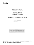
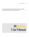
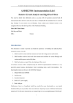
BMS-001 Owner's Manual Table of Contents BMS-001 .............................................................................. Owner's Manual ................................................................... Introduction To This Manual ................................................. What is supplied ................................................................... BMS-001 Basics ................................................................... Installation ............................................................................ Wiring your BMS-001 to your bttery ...................................... Quick Setup .......................................................................... Complete Setup ................................................................... Backlight .............................................................................. Effective Capacity Learning ................................................. Servicing .............................................................................. Questions and Answers ...................................................... Glossary ............................................................................... 1 1 1 1 1 3 4 5 6 6 7 7 8 8 Copyright © Diverse Power Systems 2011 Disclaimer Diverse Power Systems makes no claim as to the accuracy or suitability of the information contained in this manual or from any other documentation. Diverse Power Systems accepts no liability for any loss or damage, which may occur as a result of improper or unsafe use of its products. Warranty is only valid if the unit has not been modified by the customer and has not been misused. WARNING: Disconnect the supply before making or breaking the connections to the battery. WARNING: Explosive gases are associated with Lead Acid batteries. Prevent flames and sparks. Provide adequate ventilation of battery during charging/discharging. WARNING: Refer to battery charger installation insturctions on how to connect and charge batteries. WARNING: Batteries are electrically alive at all times and must be treated with extreme caution. They can supply high short circuit currents, even if they appear damaged. Take care that dropping or touching of metal objects onto the battery cell does not cause short circuits. Remove any personal metal adornment such as a chain, watch or ring, which could cause short circuits and personal injury. READ THIS FIRST! BEFORE INSTALLING THE BMS001 CAREFULLY READ THE FOLLOWING INSTRUCTIONS, ESPECIALLY THE SAFETY NOTES AND WARRANTY CONDITIONS Introduction Congratulations on purchasing the Setec BMS-001 . The BMS-001 is a high quality Australian made unit that will continuously monitor your battery and act as a “fuel gauge” to estimate the state of charge and the time left until it is discharged. What is supplied 1 . BMS-001 Battery Monitor 4. Shunt wire 3. Battery Shunt 2. Mounting Bracket 5. Wiring loom with fuse & 4 way connector BMS-001 Basics The BMS-001 product is compatible with any 1 2 V Lead-Acid battery including Valve-Regulated Lead-Acid (VRLA), Absorbed Glass Mat (AGM) and Gel batteries, as well as the traditional non-sealed batteries. The BMS-001 is permanently wired in to your 1 2 V electrical system and continuously monitors the battery voltage and charge/discharge current. It uses this information, together with several parameters that are set by the user, to “model” the battery's behaviour and to estimate the actual charge in the battery. This enables it to display a simple “fuel guage” of the percentage capacity (State of Charge or SoC) of the battery. As a secondary function the BMS-001 keeps track of the battery's age since installation and estimates total charge/discharge cycles. This allows the user to determine when a battery should be replaced, as batteries are typically specified in terms of charge/discharge cycles. The current drain of the unit itself is only 3 mA, which is much less that the normal selfdischarge of a battery, so it will not materially affect the lifetime of a battery. 1 Typical display BMS-001 when installed in a battery system 1 . Battery volts - Displays the terminal voltage of the battery. 2. Battery current - Displays the charge/discharge current into or out of your battery. 3. Charge / Discharge Indicator - Allows you to verify that your charger is charging the battery correctly. Viewing discharge current is very useful to determine if your combination of loads are drawing too much current from the battery. 4. State of charge - The estimated percentage charge state of the battery. 5. Time remaining - The time remaining until the battery is discharged. 6. Total cycles - The number of charge/discharge cycles. Installation WARNING! The BMS-001 should be installed in an easily visible location, away from moisture or excessive temperature variations. The unit is not intended for outdoor use! There should also be a route for the cable to the battery box that is no greater that 5 mtrs in length. Keep the cable away from mains leads! MOUNTING THE BRACKET 1 . Screw the mounting bracket in the chosen location. Note: It must be mounted the correct way up. 2. Slide the BMS-001 on to the mounting bracket. 3. Route the main wiring loom. Note: Avoid putting any stress on the 4 way connector, leave a short loop of cable to allow the BMS-001 to be easily removed from the bracket without straining the cable. If the main loom is too long, it is suggested to coil up the spare cable neatly close to the battery rather than shortening it. Where cables pass through any part of a metal panel or cover, ensure that a cable gland or bush is fitted to the hole. Mounting Bracket 2 Wiring your BMS-001 to your battery See larger diagram for wiring 5b Brown Black 5a 3 Yellow Red 1 . Disconnect all loads from the battery by opening all the circuit breakers on your distribution panel and turn off your charger. Remove the fuse (5a) from the BMS-001 loom fuseholder. 5b connector wiring 2. Wire up the BMS-001 to the battery using the diagram for reference. 3. Install the shunt (3) in a position where its terminals cannot be shorted to ground and as close to the battery as possible. 4. Wire the shunt exactly as shown, all connections must go to the terminals shown on the diagram. 5. Double check the connections, then install the BMS-001 fuse and if possible check the voltages with a voltmeter on the BMS-001 connector. There should be +1 2V (note the polarity) between the V+ terminal and the 3 other terminals. The BMS-001 is protected from misconnection. 6. Plug in the BMS-001 . The LCD should display battery volts, and the current should read zero. Now proceed to setup the BMS-001 to your battery. 3 Caution Note that the shunt is rated at 1 00 A maximum. Never install the shunt in a circuit that can draw in excess of 1 00 A. In particular, very high current loads such as winches should be wired directly to the battery, and not through the shunt. Quick Setup When the BMS-001 is connected and the wiring verified, it must be adjusted to match the characteristics of your battery. To start set the battery nominal capacity, this will give a quick means to see the functions of the BMS-001 . All other parameters are left at their factory-set default values. 1 . Push and hold the Setup key - After a delay of a about 5 seconds the BMS-001 will enter Setup Mode The LH display "P1 ", with small "SETUP" The RH display will read “1 00”, with the small “Ah” Push the ▼ &▲ keys to adjust this value to the battery's nominal capacity. (When the correct value is showing, after about 30 seconds the BMS001 will exit from this mode if no keys are pushed. The values will be written to the internal memory). Now you need to charge your battery. 1 . Turn on your charger. 2. Wait until the small “%” indicator flashes and the SoC value is 1 00% and all segments of the bargraph are on. This indicates that the battery is at 1 00% charge, and that the BMS-001 has recognised this and set the SoC to 1 00%. The BMS-001 is now usable, but is is suggested strongly that you read the following Complete Setup section carefully and make further changes to the BMS-001 setup. 4 Complete Setup Set up key To enter Setup Mode hold the Setup key for about 5 seconds. The BMS-001 will display various parameters and allow you to view and change your values if required. The “SETUP” indicator on the LCD will be shown. The number of the parameter is given on the LH display, and its value on the RH display, with the units being shown below. The BMS-001 will exit from this mode after about 30 seconds if no keys are pushed, (the values will be written to the internal memory). Push the Setup button to advance to the next parameter. Pushing the ▼ & ▲ keys adjust the parameter's value within certain limits. Holding the ▼ or ▲ keys down gives an auto increment feature. After the initial 5 setup parameters, pushing the Setup key again shows a further series of parameters, which are more rarely used. For these values, the units are not shown, and the “ENG” (short for “engineering”) indicator is shown on the LCD. These values should be changed with caution, after the user has understood their effect on the operation of the BMS001 . Holding the ▼ &▲ keys down together for about 1 0 seconds will reset all the parameters to their default values, the unit will restart. Many of these parameters require that you supply details from the datasheet of your battery. Contact your supplier for a datasheet. If unsure, leave the value at the default setting. Backlight The BMS-001 is provided with a display backlight, which allows the unit's display to be viewed even in very low light. The backlight is turned on whenever any of the four keys on the front panel is pressed. After about 30 seconds with no keys being pushed, the backlight will turn off. To turn on the backlight press the Light key. Press the Light key again to turn the backlight off. To keep the backlight on permanently, push and hold the Light key for 5 seconds the backlight blink. Now the backlight is permanently on. To turn it off push the Light key again. Note: The backlight consumes around 50mA when on, so it does drain the battery slightly, at a rate of about 1 Ah every 20 hours. 5 Nominal Battery Capacity (P1 ) All lead-acid batteries are sized by their capacity at the “20 hour rate”, which is the current that they can supply if discharged at a constant current for 20 hours. For typical batteries this is from 50Ah upwards. The actual capacity of a battery depends on many factors, and decreases markedly with age or if a battery has been mistreated. This value will be printed on the side of the battery, or will be available from the manufacturer. It is essential to get the value correct, else the BMS-001 will not be able to estimate state of charge correctly, and the value displayed will be grossly incorrect. If this value is unknown, it may be left at the default value of 1 00Ah, and the BMS-001 will “learn” the actual capacity over a number of charge discharge cycles, usually about 5 cycles. Battery Age (P2) As mentioned batteries lose capacity over time, and the BMS-001 tracks the age of your battery as an aid to estimate capacity. In the event that the BMS-001 is not used with a new battery, the initial age (in months) can be set. If unknown, make a guess. Battery Temperature (P3) The temperature at which the battery is used has an effect on the self-discharge rate, which expresses how the battery loses charge when it is stored. Set this to a typical storage temperature, default is 25°C. The value has a relatively minor effect on the self discharge estimation. Battery Low Voltage Alarm (P4) The BMS-001 can alert the user if the battery voltage falls below a threshold. This should be left at the default value of 11 .0V, or push the ▼ key until the value is “--.-” to disable it. Full Discharge Threshold (P5) Sets voltage threshold for the BMS-001 to consider the battery fully discharged. Leave set to the default value of 1 0.5V, see the following section “Effective Capacity Learning”. Battery Charge/Discharge Cycles (P6) Battery life is usually listed in terms of the total number of charge/discharge cycles. One such cycle is equivalent to fully discharging a battery, and then fully charging a battery. A typical lifetime is 400 cycles, though this is under ideal conditions. The BMS-001 estimates a count of these cycles. This value may be set to an explicit value, but if unknown it is recommended to leave it set to zero, so the the BMS-001 will indicate cycles since the BMS-001 was installed. 6 Effective Capacity Learning The BMS-001 will “learn” the actual capacity of your battery under typical operating conditions. This process relies on the battery being in a fully charged state, and then being discharged to near complete discharge. The BMS-001 senses a full charged battery when the terminal voltage exceeds 1 3.5V and the charge current is below 0.2% of the nominal capacity (this is 0.2A for a 1 00Ah battery). When full charge is sensed the State of Charge display will show 1 00% and the “%” symbol will flash. The BMS-001 senses a fully discharged battery when the terminal voltage is below 1 0.5V. Note that this value may need to be adjusted depending on your battery system, in particular whether you have a Low Voltage Disconnect already installed. Now your BMS-001 is ready for use, but it is suggested to first perform at least two full charge/discharge cycles to allow the BMS-001 to learn the battery's actual capacity. It is suggested that you allow a full day for this. 1 . Use the Setup Mode to view the Battery Capacity parameter. It should be what you set in the previous step. 2. Charge the battery until the State of Charge reads 1 00% and the “%” symbol is flashing. This indicates Full Charge Sync. 3. Switch a typical load onto the battery, e.g some lights, perhaps a TV or radio. The load should be about 1 0% - 20% of your battery's rated capacity. Wait until the State of Charge is reading close to zero and the “%” symbol is flashing. This indicates that your battery is nearly fully discharged. 4. Remove the load promptly else you might damage your battery. 5. View the Battery capacity parameter. It should have changed to a new value that is a better estimate of your battery's actual capacity. 6. Repeat steps 2 through 5 at least once more. You should see the capacity estimate converging to the true actual battery capacity. Servicing The BMS-001 is constructed in Australia of high quality components and should require no maintenance beyond maintaining good connections to the battery. It does have an inline fuse to protect itself from power surges, however if this fuse blows it should only be replaced by a fuse of the same rating. A blown fuse is an indicator of some other serious fault in your power system, which should be checked by an appropriate professional auto-electrician. Clean with a soft damp cloth, never use solvents to clean you BMS-001 . Do not attempt to disassemble the BMS-001 . There are no user-serviceable parts inside. 7 Questions and Answers Q. No display on the unit or the unit keeps resetting. A. - Make sure that the connections to the battery and shunt are secure. - Check the inline fuse is not blown. - Reset the unit by removing and replacing the inline fuse. - Return the unit for service if the faults continue. Q. The current reading is obviously incorrect. A. - Verify that all loads are returned to the shunt terminal and not to the battery terminal. - Verify that the shunt is clean and not shorting to the chassis. - If the CHARGE/DISCHARGE indication is reversed, then the shunt leads are reversed. Q. The unit shows “DISCHARGING” when it is charging. A. - The Isense+ and Isense- connections have been reversed. Verify the connection. Glossary Terminal Voltage - The battery voltage measured at the terminals. Measuring at the terminals allows anyvoltage drop in anywiring to be eliminated from the measurement. Nominal Capacity - The manufacturer's rated capacity for the battery in Ah over a standard discharge time (usually 20 hours) Actual Capacity - The measured or learned capacity for a given battery under service conditions. Usually this is less than the Nominal Capacity. Technical specifications Operating voltage on +V terminal: 5 V - 1 5 V Operating voltage on I+, IV- terminals: +/- 1 00 m V The device can withstand reverse connection to the battery on the +V, I+, IV- terminals and is protected to SAE J111 3-11 2000. All voltages are with respect to the -P terninal. Environmental conditions: Temperature range: -1 0 °C to 60 °C Operating Altitude: <2000 m Housing rating: IP45 Fuse is a "3 AG 1 Amp fast blow". 8 Replacement fuses: - Littelfuse #031 2001 .HXP - Cooper Bussmann #AGC-1 -R - Dick Smith #DSAU_P9672 - Jaycar #SF21 9 0 ONE YEAR LIMITED WARRANTY Diverse power systems BMS-001 BATTERY MONITOR IMPORTANT: Evidence of original purchase is required. WARRANTOR: Diverse Power Systems Warranty only available in original country of purchase. ELEMENT OF WARRANTY Diverse Power Systems warrants to the original retail owner for the duration of this warranty, its BMS-001 Battery Monitor (herein referred to as the product), to be free from defects in materials and craftsmanship with only the limitations or exclusions set out below. Warranty duration: This warranty to the original retail owner only, shall terminate and be of no further effect ONE (1 ) year after the date of original retail sale. This warranty will be deemed invalid if the Product; (A) Damaged or not maintained as reasonable and necessary, (B) Modified, altered or used as part of any conversion kits, subassemblies, or any configurations not sold by setec. (C) Improperly installed (D) Repaired by someone other than an authorised Diverse Power Systems Repair Agent for a detect or malfunction covered by this warranty (E) Used in conjunction with any equipment or parts or as part of a system not manufactured by Diverse Power Systems. (F) Where the serial number label of the product has been removed or damaged beyond recognition. Warranty only valid in the country of original retail/sale. Our goods come with guarantees that cannot be excluded under the Australian Consumer Law. You are entitled to a replacement or refund for a major failure and for compensation for any other reasonably foreseeable loss or damage. You are also entitled to have the goods repaired or replaced if the goods fail to be of acceptable quality and the failure does not amount to a major failure. PARTS COVERED This warranty covers for one (1 ) year, of the product and included accessories. STATEMENT OF REMEDY If in the event that the product does not conform to this warranty at any time while this warranty is in effect, the warrantor at its discretion, will repair the defect or replace the product and return it to you without charge for parts or service. This warranty does not provide for the reimbursement or payment of incidental or consequential damages. PROCEDURE FOR OBTAINING PERFORMANCE OR WARRANTY: In the event that the product does not conform to this warranty, the Product should be shipped or delivered, freight pre-paid, with evidence of original purchase (eg a copy of the sales docket), point of purchase. DESIGNED AND MANUFACTURED IN AUSTRALIA DOC BMS-001 User Manual 0221 30 Rev B