1
•
•
•
•
•
•
•
•
•
•
•
•
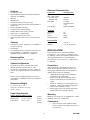
Features
Electrical Characteristics
19 stations or zones
Built-in talkback amplifier for handsfree talkback
operation (V-119RTHF)
Dial tone
Ringback tone
Last number dialed re-ring (tone only)
Conference calling on tone dial systems (handset to
handset only)
Personal signaling (tone only)
Combined rotary and tone dialing
Speaker inhibit (with 1A2 key systems)
Splash tone (V-119RTHF only)
15 second repeat alert tone option
Optional all call (requires V-1118 one-way all call
unit)
Parameters
Input Imp. T and R
Max. Cable Length
One-Way Page
Talkback Page
Dial Pulses
Capacity
•
•
•
The capacity of the V-119RTVA or V-119RTHF is
19 zones or stations.
One talkpath.
The maximum number of speakers on a zone is two
45 ohm talkback (V-119RTHF) or 40 one-way
amplified speaker assemblies (V-119RTVA).
The dialing codes are: 0, 1, 3-9, 20-29.
•
For talkback, use the V-119RTHF and 45 ohm
talkback speakers (maximum two per zone).
For one-way voice announce, use the V-119RTVA
with one-way amplified speakers (maximum 40 per
zone).
Tone Signals
5000 Feet
800 Feet
8-12 PPS
60-40 Break ratio
+10%
Industry Standard
Frequency
Bandwidth
Twist
Detect
Interdigital Time
3%
6db
40 MS
40 MS
Environmental
Temperature
Humidity
0/ to 50/ C
0/ to 85/ Non-precip.
INSTALLATION
These instructions cover only the installation
procedures for the Valcom V-119RTVA and
V-119RTHF. Consult the installation instructions for
other equipment that may be used. Installation
procedures are the same for the V-119RTVA and
V-119RTHF.
Numbering Plan
•
Working Limits
600 Ohm (incl.inst.)
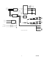
System Configuration
•
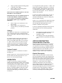
Precautions
All precautions have been taken at the factory to
insure that the equipment functions properly. To
insure proper operation and to prevent equipment
damage, please observe the following:
• Unplug the power supply before making any
connections to the control unit.
• Do not locate the control unit closer than 18
inches or farther than 5 feet from the power
supply.
• Do not use a lamp tester to check signals, use a
voltmeter. A lamp tester when first applied is a
short circuit to electronic circuits.
• Do not apply power to the control unit until all
connections have been double-checked.
NOTE: One-way amplified speakers may also be
used with the V-119RTHF in areas where talkback is
not required.
Dimensions/Weight
•
•
7.1" H x 5.9" W x 2.1" D
(18.03 cm x 14.99 cm x 5.33 cm)
3.5 lbs. (1.6 kg)
Power Requirements
Voltage Working Limits Current
Talk battery
–21.5 to –26 Vdc
Signal battery
–21.5 to –26 Vdc
Lamp battery
9V to 11 Vac
Mounting
Mount the V-119RTVA or V-119RTHF on a 7" KTU
mounting, relay rack, or on the wall.
60 mA
250 mA
45 mA
per lamp
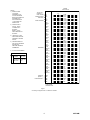
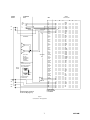
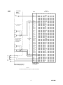
Connections
__ 1.
2
Fasten a 25 pair female amphenol ended
cable to the unit and terminate all leads on a
66 type block.
947120M