1
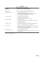
VSP-V-119RTVA/119RTHF
Issue 7
V-119RTVA VOICE ANNOUNCE
V-119RTHF HANDSFREE TALKBACK
19 ZONE INTERCOM/PAGE CONTROL UNITS
GENERAL
These instructions provide identification, installation,
operation, connection and maintenance information
for the V-119RTVA voice announce and
V-119RTHF handsfree talkback intercom/page
control units.
The V-119RTVA and V-119RTHF are single-path
dial select microprocessor controlled intercom/page
control units to be used with PABX, Electronic Key
or 1A2 Key Telephone Systems.
This paging unit has received an FCC type KX
registration and is designed to be used with FCC
registered key telephone systems. Installations may
be made by Valcom, Inc., telephone equipment
manufacturers, telephone companies, registered
telephone refurbishers, and those qualified for
installation of FCC registered systems under FCC
Rules Section 68.215.
In accordance with FCC rules with applicable tariffs,
this intercom unit may only be installed with the
authorization of the owner of the host system.
•
•
•
•
The FCC Registration No. BAFUSA-69358-KX-N,
will be listed in the affidavits filed with the telephone
company; it will also be recorded in the system log
kept by installation and maintenance personnel. The
local telephone company is to be notified of the FCC
Registration Number when this intercom unit is
installed.
designed to provide reasonable protection against
such interference. If this unit does cause interference
to radio and television reception, which can be
determined by turning the equipment off and on, the
user is encouraged to try to correct the interference by
one or more of the following measures:
Reorient the receiving antenna.
Relocate the equipment with respect to the receiver.
Plug the equipment into a different branch circuit.
Move the equipment away from the receiver.
SPECIFICATIONS
Purpose
•
This equipment generates and uses radio frequency
energy and if not installed and used properly, that is,
in strict accordance with the manufacturer's
instructions, may cause interference to radio and
television reception. It has been tested and found to
comply with the limits for a Class B computing
device, in accordance with the specifications in
Subpart J of Part 15 of the FCC Rules, which are
•
To provide 19 stations or zones of handsfree talkback
to 1A2 key systems, electronic key systems, or
PABX trunk positions (V-119RTHF).
To provide 19 zones of voice announce signaling to
1A2 key systems, electronic key systems, or PABX
trunk positions (V-119RTVA).
•
•
•
1A2 key systems
Electronic key system line key position
PABX loop start trunk position
Applications
1
947120M
•
•
•
•
•
•
•
•
•
•
•
•
Features
Electrical Characteristics
19 stations or zones
Built-in talkback amplifier for handsfree talkback
operation (V-119RTHF)
Dial tone
Ringback tone
Last number dialed re-ring (tone only)
Conference calling on tone dial systems (handset to
handset only)
Personal signaling (tone only)
Combined rotary and tone dialing
Speaker inhibit (with 1A2 key systems)
Splash tone (V-119RTHF only)
15 second repeat alert tone option
Optional all call (requires V-1118 one-way all call
unit)
Parameters
Input Imp. T and R
Max. Cable Length
One-Way Page
Talkback Page
Dial Pulses
Capacity
•
•
•
The capacity of the V-119RTVA or V-119RTHF is
19 zones or stations.
One talkpath.
The maximum number of speakers on a zone is two
45 ohm talkback (V-119RTHF) or 40 one-way
amplified speaker assemblies (V-119RTVA).
The dialing codes are: 0, 1, 3-9, 20-29.
•
For talkback, use the V-119RTHF and 45 ohm
talkback speakers (maximum two per zone).
For one-way voice announce, use the V-119RTVA
with one-way amplified speakers (maximum 40 per
zone).
Tone Signals
5000 Feet
800 Feet
8-12 PPS
60-40 Break ratio
+10%
Industry Standard
Frequency
Bandwidth
Twist
Detect
Interdigital Time
3%
6db
40 MS
40 MS
Environmental
Temperature
Humidity
0/ to 50/ C
0/ to 85/ Non-precip.
INSTALLATION
These instructions cover only the installation
procedures for the Valcom V-119RTVA and
V-119RTHF. Consult the installation instructions for
other equipment that may be used. Installation
procedures are the same for the V-119RTVA and
V-119RTHF.
Numbering Plan
•
Working Limits
600 Ohm (incl.inst.)
System Configuration
•
Precautions
All precautions have been taken at the factory to
insure that the equipment functions properly. To
insure proper operation and to prevent equipment
damage, please observe the following:
• Unplug the power supply before making any
connections to the control unit.
• Do not locate the control unit closer than 18
inches or farther than 5 feet from the power
supply.
• Do not use a lamp tester to check signals, use a
voltmeter. A lamp tester when first applied is a
short circuit to electronic circuits.
• Do not apply power to the control unit until all
connections have been double-checked.
NOTE: One-way amplified speakers may also be
used with the V-119RTHF in areas where talkback is
not required.
Dimensions/Weight
•
•
7.1" H x 5.9" W x 2.1" D
(18.03 cm x 14.99 cm x 5.33 cm)
3.5 lbs. (1.6 kg)
Power Requirements
Voltage Working Limits Current
Talk battery
–21.5 to –26 Vdc
Signal battery
–21.5 to –26 Vdc
Lamp battery
9V to 11 Vac
Mounting
Mount the V-119RTVA or V-119RTHF on a 7" KTU
mounting, relay rack, or on the wall.
60 mA
250 mA
45 mA
per lamp
Connections
__ 1.
2
Fasten a 25 pair female amphenol ended
cable to the unit and terminate all leads on a
66 type block.
947120M
__ 2.
__ 3.
To re-ring the same station, press the "*" button. The
station will be signaled as long as the "*" is pressed.
Personal signaling: When initiating a call, press the
"*" and then the station number. A double tone will
be sent to the called speaker. No voice announce or
talkback will be possible.
Strap A ground, B ground and lamp ground
common at power supply.
Refer to Figure 1 for connecting block
layout and connections.
Limit cable runs to talkback speakers to not more
than 800 feet. Do not split pairs.
To dial a new number (tone dial only), press the "#"
button. The speaker for the first number will be
disconnected and dial tone returned to calling party.
Dial new number and page.
Limit audio runs to one-way amplified speakers to
not more than 5000 feet. Limit power runs to
one-way speakers to maximum recommended for
the particular speaker type (see applicable
instruction).
__ 4.
__ 5.
NOTE: If "#" is pressed after the speakers have been
inhibited additional numbers may still be dialed. A
tone will signal the called party but no voice
announce or talkback will be possible.
Refer to Figure 2 for connections to 1A2
Key Systems.
Refer to Figure 3 for connections to
electronic line key or PABX loop start trunk
positions.
To achieve maximum performance from this system,
the user should receive the following operating
instructions:
Settings
a.
Wire Jumper JP1 controls the 15 second Repeat Alert
Tone. The Repeat Alert Tone is disabled with the
jumper in place and is enabled by cutting or removing
the jumper.
b.
For off-hook speaker cancel circuit, each ICM "A"
lead must be connected through a 10K 1/4 W 5%
resistor to the inhibit input (GN/V) (refer to Figure
2). When "called" station or any other party goes
off-hook, the presence of two resistance grounds
cancels or turns off speaker. "Handsfree" mode can
only be restored by terminating call and redialing
station.
The calling party should speak directly into
the telephone mouthpiece and avoid
speaking too softly.
The called party must wait (approximately
1/2 second) before responding to the calling
party.
CIRCUIT DESCRIPTION
General Method of Operation
This unit provides dial intercom access to interface
with the telephone system being used. A one-way
(V-119RTVA) or two-way (V-119RTHF) amplifier
conditions the speech from the telephone system tip
and ring, and provides a low impedance, low level
output to the desired speaker via conventional
telephone wiring, i.e. house cable or station wire.
Volume Controls
The phone to speaker level should be at a normal
listening level.
Detailed Description
Speaker to phone level: this is the most critical level;
set the volume at the lowest practical level. (It is
better to set it too low than too high).
When a station user lifts handset to make an ICM
page, the switchhook contacts in the telephone close
the tip and ring to form a loop which returns battery
back to turn on a transistor which operates relay and
logic circuit to return dial tone and lamp battery to
telephone set. Logic circuit receives dialing
information and operates relays and circuitry to
supply splash tone and voice connection for station
selected. When called or any other party goes
off-hook on ICM path, the presence of two resistance
grounds cancels or turns off speakers if inhibit
resistors are wired. "Handsfree mode" can only be
restored by terminating call and redialing station.
OPERATION
To make a voice page, go off-hook and dial the
number of the desired zone or station. Dial tone will
be broken after the first number is dialed. A one-half
second ringback tone will indicate that the called
zone is being signaled. After the tone, proceed with
the page. If using the talkback control unit, called
party may answer handsfree. If speaker cancel is
wired, when called party goes off-hook, speaker will
be turned off.
3
947120M
TECHNICAL ASSISTANCE
If the trouble has not been located, refer to Table 1.
This chart identifies symptoms of some possible
problems and solutions.
When trouble is reported, verify that:
•
•
•
•
All telephone sets are in proper working order;
Power is being supplied to the unit;
There are no broken connections at the
connecting block;
The conductors of color-coded cables are
terminated in the proper order.
If a spare unit is available, continue to troubleshoot
by substituting the spare unit for the specified unit.
If, after all the required test have been performed, the
trouble still exists, assistance in troubleshooting is
available from the factory. When calling, you should
have a VOM, a telephone test set and several slip
leads available and be calling from the job site. Call
(540) 427-3900 and ask for Technical Support, or
call (540) 427-6000 for Valcom 24-hour Automated
Support or visit our website at
http://www.valcom.com.
If trouble still exists, the test equipment listed below
shall be required:
•
•
•
•
Volt-ohm-multimeter
Tone-dial single line instrument (for tone dial
systems)
Telephone test set
Clip leads
The V-119 is not field repairable. Valcom
equipment contains no user serviceable parts
inside. Valcom, Inc., maintains service facilities in
Roanoke, VA. Should repairs be necessary, attach a
tag indicating company name, address, phone
number, contact person, and the nature of the
problem. Send the unit to:
Test lamps must not be used to check voltages. They
can damage electronic circuits. When a hand test set
is used to check voltages, the results will be
misleading.
Before proceeding further, check the voltages at the
connecting block. An undetected blown fuse or low
voltage will cause improper control operation. DC
voltage measurements are made with respect to (+)
ground.
Valcom, Inc.
Repair and Return Dept.
5614 Hollins Road
Roanoke, VA 24019-5056
VALCOM LIMITED WARRANTY
Valcom, Inc. warrants its products to be free from defects in materials and workmanship under conditions of normal use and service
for a period of one year from the date of shipment. The obligation under this warranty shall be limited to the replacement, repair or
refund of any such defective device within the warranty period, provided that:
1.
2.
3.
4.
5.
inspection by Valcom, Inc. indicates the validity of the claim,
the defect is not the result of damage, misuse, or negligence after the original shipment.
the product has not been altered in any way or repaired by others and that factory sealed units are unopened (A service
charge plus parts and labor will be applied to units defaced or physically damaged),
freight charges for the return of products to Valcom are prepaid,
all units ‘out of warranty’ are subject to a service charge. The service charge will cover minor repairs (Major repairs will
be subject to additional charges for parts and labor).
This warranty is in lieu of and excludes all other warranties, expressed or implied, and in no event shall Valcom, Inc. be
liable for any anticipated profits, consequential damages, loss of time or other losses incurred by the buyer in connection
with the purchase, operation, or use of the product.
This warranty specifically excludes damage incurred in shipment. In the event a product is received in damaged condition, the
carrier should be notified immediately. Claims for such damage should be filed with the carrier involved in accordance with the
F.O.B. point.
Headquarters:
Valcom, Inc.
1111 Industry Avenue
Roanoke, VA 24013
Phone: (540) 427-3900
FAX: (540) 427-3517
In Canada
CMX Corporation
35 Van Kirk Drive #11 and 12
Brampton, Ontario L7A1A5
Phone: (905) 456-1072
FAX: (905) 456-2269
4
947120M
TABLE 1
TROUBLESHOOTING CHART
PROBLEM
PROBABLE CAUSES AND CORRECTIONS
No Side Tone
Check "A" battery connections, polarity and voltage.
No Dial Tone
Check "A" and "B" battery connections, polarity and voltage
1. Check phone to speaker control.
2. Check* for audio present at tip, ring input BL/WH, WH/BL pair.
3. Check* for audio at signaled speaker pair at 66 block.
4. Check* for audio at input of speaker.
No Volume to Speaker
No Volume to Phone
1. Check speaker to phone volume control.
2. Check wiring to talkback speaker.
3. Remove all connections to inhibit pin and verify.
Hum Heard at Phone
1. Check wiring to speaker.
2. Possible magnetic interference from power supply - relocate unit and
cables at least 18" away.
3. Check for noisy "A" battery.
No Speaker Cancel
1. Verify ground present at phone side of at least (2) 10K ohm resistors.
NOTE: Do not apply ground directly to inhibit input.
R. F. Interference
1. Strap from V-119 chassis to A GND and B GND on punchdown block.
Continue strap to earth or water pipe ground.
2. Connect .05 mfd ceramic disc capacitor from each side of each speaker
pair to B ground on punchdown block.
Crosstalk Between Zones
1. Failure to use twisted pair wiring.
2. Load speaker output pair at block by connect a 1/2 watt 47 ohm resistor
across output pair.
*Use lineman's test set (Butt set)
5
947120M
NOTES:
1) INHIBIT OPTION:
TO CANCEL
SPEAKERS, A 10K
1/4W 5% RESISTOR
MUST BE CONNECTED
IN SERIES WITH
EACH ICM BUTTON
"A" LEAD AND THE
INHIBIT LEAD.
66B350
SPLIT BLOCK
A
T and R from
LINE KEY or
LOOP TRUNK
POWER SUPPLY
LINE KEYS
T
R
LS
L
LG
PC
R0
SPK 0
R1
SPK 1
R3
SPK 3
R4
SPK 4
R5
SPK 5
R6
SPK 6
R7
SPK 7
R8
SPK 8
R9
SPK 9
R 20
SPK 20
R 21
SPK 21
R 22
SPK 22
R 23
SPK 23
R 24
SPK 24
R 25
SPK 25
R 26
SPK 26
R 27
SPK 27
R 28
SPK 28
R 29
SPK 29
PAGE CONTROL
2) POWER SUPPLY:
A BATT. -24VDC
FILTERED TALK
BATTERY.
B BATT. -24VDC
UNFILTERED RELAY
BATTERY.
3) LAMP GND., A GND.,
AND B GND, MUST BE
COMMON AT POWER
SUPPLY.
4) FOR BEST RESULTS
USE 45 ohm SPEAKERS
OR ONE-WAY
AMPLIFIED SPEAKER
ASSEMBLIES.
SPEAKERS
5) OPTION PROGRAMMING:
OPTIONS
JP1
Installed
Open or Cut
No Repeat
Alert Tone
Repeat Alert
Tone
ICM KEYS
(NOTE 1)
INH
AG
AB
BG
BB
POWER SUPPLY
B
26
1
27
2
28
3
29
4
30
5
31
6
32
7
33
8
34
9
35
10
36
11
37
12
38
13
39
14
40
15
41
16
42
17
43
18
44
19
45
20
46
21
47
22
48
23
49
24
50
25
C
D
E
F
W/BL
BL/W
W/O
O/W
W/GR
GR/W
W/BR
BR/W
W/S
S/W
R/BL
BL/R
R/O
O/R
R/G
G/R
R/BR
BR/R
R/S
S/R
BK/BL
BL/BK
BK/O
O/BK
BK/G
G/BK
BK/BR
BR/BK
BK/S
S/BK
Y/BL
BL/Y
Y/O
O/Y
Y/G
G/Y
Y/BR
BR/Y
Y/S
S/Y
V/BL
BL/V
V/O
O/V
V/G
G/V
V/BR
BR/V
V/S
S/V
CABLE FROM
CONTROL UNIT
Figure 1
Connecting Arrangements for V-119RTVA/V-119RTHF
6
947120M
TELEPHONE
SETS
POWER
SUPPLY
66B350
SPLIT BLOCK
MDF
A
TIP
RING
LG
L
A
LG
T
R
LS
L
LG
Note 1
LB
STATION 0
SPEAKERS
Up To Two
45 ohm
Speakers Or
40 Speaker/
Amplifier
Assemblies.*
STATIONS
0-29
Note 1:
Connect ICM "A" Lead
From Each Telephone
To A 10K Resistor.
ICM "A"
LEADS
INH
Connect Resistors
To Inhibit Lead.
AG
STA 29
AB
BG
BB
PC
R0
SPK 0
R1
SPK 1
R3
SPK 3
R4
SPK 4
R5
SPK 5
R6
SPK 6
R7
SPK 7
R8
SPK 8
R9
SPK 9
R 20
SPK 20
R 21
SPK 21
R 22
SPK 22
R 23
SPK 23
R 24
SPK 24
R 25
SPK 25
R 26
SPK 26
R 27
SPK 27
R 28
SPK 28
R 29
SPK 29
INH
AG
AB
BG
BB
B
C
D
E
F
W/BL
BL/W
W/O
O/W
W/GR
GR/W
W/BR
BR/W
W/S
S/W
R/BL
BL/R
R/O
O/R
R/G
G/R
R/BR
BR/R
R/S
S/R
BK/BL
BL/BK
BK/O
O/BK
BK/G
G/BK
BK/BR
BR/BK
BK/S
S/BK
Y/BL
BL/Y
Y/O
O/Y
Y/G
G/Y
Y/BR
BR/Y
Y/S
S/Y
V/BL
BL/V
V/O
O/V
V/G
G/V
V/BR
BR/V
V/S
S/V
25 PAIR CABLE
FROM V-119RTVA
or V-119RTHF
*Speaker/Amplifier Assemblies
Are For One-Way Page Only
Figure 2
Connections to 1A2 Key Systems
7
947120M
POWER
SUPPLY
LOOP START
TRUNK
POSITION
66B350
SPLIT BLOCK
MDF
A
TIP
RING
T
R
LS
L
STATION 0
SPEAKERS
Up to Two 45 ohm
Speakers Or 40
Speaker/Amplifier
Assemblies*.
AG
STATIONS
0-29
STATION 29
AB
BG
BB
PC
R0
SPK 0
R1
SPK 1
R3
SPK 3
R4
SPK 4
R5
SPK 5
R6
SPK 6
R7
SPK 7
R8
SPK 8
R9
SPK 9
R20
SPK 20
R21
SPK 21
R22
SPK 22
R23
SPK 23
R 24
SPK 24
R25
SPK 25
R26
SPK 26
R 27
SPK 27
R28
SPK 28
R29
SPK 29
INH
AG
AB
BG
BB
B
C
D
E
F
W/BL
BL/W
W/O
O/W
W/GR
GR/W
W/BR
BR/W
W/S
S/W
R/BL
BL/R
R/O
O/R
R/G
G/R
R/BR
BR/R
R/S
S/R
BK/BL
BL/BK
BK/O
O/BK
BK/G
G/BK
BK/BR
BR/BK
BK/S
S/BK
Y/BL
BL/Y
Y/O
O/Y
Y/G
G/Y
Y/BR
BR/Y
Y/S
S/Y
V/BL
BL/V
V/O
O/V
V/G
G/V
V/BR
BR/V
V/S
S/V
25 PAIR CABLE
FROM V-119RTVA
or V-119RTHF
*Speaker/Amplifier Assemblies
Are For One-Way Page Only
Figure 3
Connections to Electronic line Key or Loop Start Trunk Position
8
947120M
SW1
SW2
A GROUND
A BATTERY
TIP
RING
K1
BATTERY
FEED
MICROPROCESSOR
K2
K8
VOICE ANNOUNCE
OR
HANDSFREE CIRCUIT
TONE DECODER
K1
S1
S2
K1
S8
S9
K3
K4
K5
B GROUND
S20
POWER
SUPPLY
K2
K3
K7
B BATTERY
K6
LAMP SUPPLY
K4
S21
S28
K5
K2
S29
K8
R0
LAMP
PAGE CONTROL
K8
R1
R3
R29
SIMPLIFIED SCHEMATIC DIAGRAM
9
947120M