1
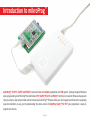
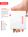
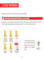
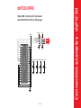
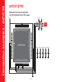
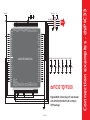
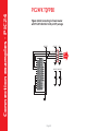
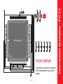
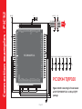
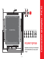
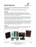
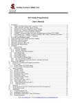
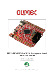
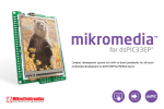
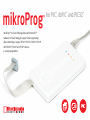
mikroProg
™
mikroProg™ is a fast USB programmer with mikroICD™
hardware In-Circuit Debugger support. Smart engineering
allows mikroProg to support PIC10®, PIC12®, PIC16®, PIC18®,
dsPIC30/33®, PIC24® and PIC32® devices
in a single programmer!
for PIC®, dsPIC® and PIC32®
TO OUR VALUED CUSTOMERS
I want to express my thanks to you for being interested in our products and for having
confidence in MikroElektronika.
The primary aim of our company is to design and produce high quality electronic products
and to constantly improve the performance thereof in order to better suit your needs.
Nebojsa Matic
General Manager
The PIC®, dsPIC®, PIC24®, PIC32® and Windows® logos and product names are trademarks of Microchip Technology® and Microsoft® in the U.S.A. and other countries.
Page 2
Table of Contents
Introduction to mikroProg™ 4
Key features
5
1. Driver installation
6
step 1 – Start installation
7
step 2 – Accept EULA
7
step 3 – Installing the drivers
8
step 4 – Finish installation 8
2. Connecting to a PC
9
3. mikroProg Suite™ for PIC® software
10
4. Powering device via mikroProg™
11
5. Connecting with a target device
12
6. IDC10 Pinout
13
7. Connection examples
14
Using 1x5 male headers
14
Using 2x5 male headers
15
8. Multiplexer
16
Multiplexer in idle mode
18
Multiplexer in programming/debugging mode
19
10. Examples of connection schematics Page 3
20
Introduction to mikroProg™
mikroProg™ for PIC®, dsPIC® and PIC32® represents fast and reliable programmer with ICD support. Specially designed firmware
allows programming of all Microchip® microcontrollers: PIC®, dsPIC®, PIC24® and PIC32®. And there’s no need for firmware change each
time you select a new microcontroller architecture because mikroProg™ firmware takes care of all supported architectures. Supporting
new microcontrollers is easy. Just by downloading the latest version of mikroProg Suite™ for PIC® your programmer is ready to
program new devices.
Page 4
Key features
- In-Circuit Debugging (ICD).
- One firmware for PIC®, dsPIC®, PIC24®
and PIC32® microcontroller families
- New microcontrollers support via latest version of mikroProg™ Suite
for PIC® software
- Can provide power supply for target
device
01
02
03
04
05
01 Flat cable
06
02 USB MINIB connector
03 DATA transfer indication LED
04 ACTIVE indication LED
05 LINK indication LED
06 POWER indication LED
Page 5
1. Driver installation
mikroProg™ requires drivers in order to work. Drivers are located on the link bellow:
http://www.mikroe.com/downloads/get/1202/mikroprog_for_pic_drivers_v200.zip
When you locate the drivers, please extract files from the ZIP archive. Folder with extracted files contains folders with drivers for
different operating systems. Depending on which operating system you use, choose adequate folder and open it.
In the opened folder you should be
able to locate the driver setup file.
Double click on setup file to begin
installation of the programmer
drivers.
Page 6
step 1 – Start installation
step 2 – Accept EULA
01
01
02
01 In welcome screen click on Next> button
01 In order to proceed select: I accept the this EULA
(End User License Agreement)
02 Click Next> button
Page 7
step 3 – Installing the drivers
step 4 – Finish installation
01
01
01 Click on Finish button to end installation process
01 Drivers are installed automatically
Page 8
2. Connecting to a PC
After driver installation is complete, you can now connect the programmer with your PC using
USB cable provided with the package. Green POWER LED should turn ON, indicating the presence
of power supply. Amber-colored LINK LED will turn ON when link between mikroProg™ and PC is
established. Link can be established only when correct drivers are installed on your PC.
Page 9
3. mikroProg Suite™ for PIC® software
mikroProg Suite™ for PIC® software is
intended for programming PIC®, dsPIC®,
PIC24® and PIC32® microcontrollers from
Microchip®. The graphic interface of this
program is clear and easy-to-use, which
makes the use of this program faster. The
program’s main window includes basic
options for programming microcontrollers. In
addition, there are advanced programming
options that enable experienced users to
set configuration bits on their own. The
program includes views providing basic
information about the selected MCU,
voltage monitoring, etc.
Page 10
4. Powering target device via mikroProg™
One of the key benefits of mikroProg™ is that is can power your
target device. You can set power supply voltage in range from
2.7V to 5V with output current up to 250mA. This option is
activated from mikroProg Suite™ for PIC® (v2.29) software.
Click the MCU Info button to display Voltage Options section.
First you must select MCU family and choose your target
MCU from a dropdown list. mikroProg™ will automatically set
the default value of power supply for your MCU. You can also
manually set voltage supply value by moving slider under
mikroProg Suite™ for PIC® window, Figure 4-1.
02
01
To enable power supply, first set desired voltage and then click
on check box “Power board from programmer”.
03
Figure 4-1: Voltage options
01 Setting supply voltage value from 2.7 to 5V (max 250mA)
02 Check box for enabling supply voltage from programmer
03 Box with selected supply voltage
Page 11
5. Connecting with
a target device
For connection with a target device mikroProg™ uses female
IDC10 connector, Figure 5-1. In order to make proper connection
with the target board it is necessary to pay attention to IDC10
connector pinout. Every pin has a different purpose and for easy
orientation IDC10 connector is marked with a little knob and
incision, Figure 5- 2.
Figure 5-2: Knob
and incision for easy
orientation
First pin
Front side of IDC10 connector is marked with a knob and incision.
Front side holds PGC, PGD and MCLR pins which are used for
microcontroller programming.
Figure 5-1: IDC10
connector
Page 12
6. IDC10 Pinout
01 MCU-VCC - MCU power supply
03 MCU-PGC - Serial programming clock
05 MCU-PGD - Serial programming data
09
10
07
08
05
06
03
04
01
02
07 MCU-MCLR - Master clear/Programming voltage
09 GND - Ground
02 VCC
04 PGC
06 PGD
08 MCLR
These pins are
multiplexed (see
section 8.0 for more
information)
10 GND
Figure 6-1: IDC10 pinout
Page 13
Figure 7-1: Use only front
row for programming
7. Connection examples
For connecting mikroProg™ with your target device a best solution is to provide 1x5 or 2x5
male headers which are connected with programing pins on microcontroller. You can see
several examples of connection schematics in the Section 10 of this manual.
Using 1x5 male headers
When connecting mikroProg™ with your device via 1x5 header make sure to use front side
of IDC10 connector (side with a knob and incision), Figure 7-2. 1x5 programming
headers are found in some of Mikroelektronika products, like mikromedia
boards, Figure 7-2.
Figure 7-2:
Connecting
mikroProg™ to
mikromedia board
via 1x5 male header
Page 14
Figure 7-3: Use entire
IDC10 connector for
multiplexing feature
Using 2x5 male headers
By using 2x5 male connector in your device you can exploit the multiplexing feature
of mikroProg™ for PIC®, dsPIC® and PIC32®. We’ll explain how multiplexer operates and
what are it’s key benefits in Section 8 of this manual.
Figure 7-4: Connecting
mikroProg™ with Ready for PIC®
via 2x5 male header
Page 15
8. Multiplexer
Programming pins or I/Os?
Figure 8-1:
mikroProg™ 2x5
male header next
to reset button
RB7
RB6
RB5
RB4
RB3
RB2
RB1
RB0
VCC
GND
RD7
RD6
RD5
RD4
RC7
RC6
RC5
RC4
RD3
RD2
40
39
38
37
36
35
34
33
32
31
30
29
28
27
26
25
24
23
22
21
MCU-PGC
MCU-PGD
MCU-MCLR
MCU-VCC
MCLR
MCLR
RA0
RA1
RA2
RA3
RA4
RA5
RE0
RE1
RE2
VCC
GND
RA7
RA6
RC0
RC1
RC2
RC3
RD0
RD1
VCC
PGC-RB6
1
2
3
4
5
6
7
8
9
10
11
12
13
14
15
16
17
18
19
20
MCU-VCC
PGD-RB7
MCU-VCC
PIC18F45K22
Multiplexer is specially designed circuit which serves as a switch.
Purpose of multiplexer is that there’s no need for disconnecting
mikroProg™ programmer from a device when programming is
finished. Multiplexing is always available, but can only be used
with 2x5 male header on target board as shown on Figure
8-1. Multiplexer allows the usage of programming
pins (PGC and PGD) as I/O lines when not in
programming/debugging mode. Master
clear reset (MCLR) pin is also
multiplexed and can be used
for resetting target
MCU when not in
programming/
debugging
mode.
1K
R
R
10K
R
100nF
RESET
Figure 8-2: Having 2x5
programmer header,
programming lines are separated
from rest of the circuit.
While pins on MCU are separated from rest of the circuit, they can
not be used as I/O or reset pins as shown on Figure 8-2. There are
two ways to connect programming pins: 1. with mikroProg™ 2x5
female connector 2. by placing jumpers over 2x5 male header.
Page 16
Multiplexer decides pin function
MCLR
RA0
RA1
RA2
RA3
RA4
RA5
RE0
RE1
RE2
VCC
GND
RA7
RA6
RC0
RC1
RC2
RC3
RD0
RD1
RB7
RB6
RB5
RB4
RB3
RB2
RB1
RB0
VCC
GND
RD7
RD6
RD5
RD4
RC7
RC6
RC5
RC4
RD3
RD2
40
39
38
37
36
35
34
33
32
31
30
29
28
27
26
25
24
23
22
21
MCU-PGC
MCU-PGD
MCU-MCLR
VCC
MCU-VCC
PGC-RB6
PGD-RB7
MCLR
1
2
3
4
5
6
7
8
9
10
11
12
13
14
15
16
17
18
19
20
MCU-VCC
1K
R
R
10K
R
100nF
RESET
Figure 8-3: Multiplexer allows
the usage of programming pins
as I/O and MCLR pin as reset
when not in programming/
debugging mode
MCU-VCC
MCLR
RA0
RA1
RA2
RA3
RA4
RA5
RE0
RE1
RE2
VCC
GND
RA7
RA6
RC0
RC1
RC2
RC3
RD0
RD1
PIC18F45K22
1
2
3
4
5
6
7
8
9
10
11
12
13
14
15
16
17
18
19
20
MCU-VCC
PIC18F45K22
MCU-VCC
Programming pins just as I/Os
RB7
RB6
RB5
RB4
RB3
RB2
RB1
RB0
VCC
GND
RD7
RD6
RD5
RD4
RC7
RC6
RC5
RC4
RD3
RD2
40
39
38
37
36
35
34
33
32
31
30
29
28
27
26
25
24
23
22
21
MCU-PGC
MCU-PGD
MCU-MCLR
VCC
PGC-RB6
PGD-RB7
MCLR
MCU-VCC
1K
R
R
10K
R
100nF
RESET
Figure 8-4: When mikroProg™
is removed place jumpers over
2x5 male header in order to
use programming pins as I/O
and MCLR pin as reset
Programming/debugging is enabled when mikroProg™ is connected to the device. As shown on Figure 8-3, when programming/debugging
is finished, multiplexer reconnects programming/debugging pins so they can be used as I/Os. There’s no need to remove mikroProg™
connector. When mikroProg™ is removed, place jumpers over 2x5 male header in order to use programming/debugging pins as I/O, and
MCLR pin as reset (Figure 8-4). In programming/debugging mode MCLR pin is used by mikroProg™, otherwise it is used by MCU.
Page 17
Multiplexer in idle mode
mikroProg for PIC
Multiplexer
MCU-PGD
PGC
MCU-PGC
PROG
MCLR
MCU-MCLR
MCU-VCC
PGD
VCC
MCU-VCC
MCU-PGC
MCU-PGD
MCU-MCLR
VCC
DD+
GND
USB
DATA
VCC
BRD-PGC
BRD-PGD
BRD-MCLR
IDC10
connector
Figure 8-5:
Multiplexer in the
idle mode
When programming/debugging is not in progress, the multiplexer releases the programming pins and MCLR, thus enabling them to be used as
I/O pins or reset. This also enables the programmer to be connected to the target device without affecting its operation.
Page 18
Multiplexer in programming/debugging mode
mikroProg for PIC
Multiplexer
MCU-PGD
PGC
MCU-PGC
VCC
DD+
GND
PROG
MCLR
MCU-MCLR
MCU-VCC
PGD
VCC
MCU-VCC
MCU-PGC
MCU-PGD
MCU-MCLR
USB
DATA
VCC
BRD-PGC
BRD-PGD
BRD-MCLR
IDC10
connector
Figure 8-6:
Multiplexer in the
programming/
debugging mode
During programming/debugging, the multiplexer disconnects the microcontroller pins used for programming/debugging from the target device.
This enables the programming/debugging process to be safely performed without affecting the operation of the device itself. It also prevents
external signals from affecting the programming/debugging process. When the programming/debugging process has been completed, the
multiplexer releases the microcontroller pins used for programming, so that they can be used as I/O pins or reset respectively.
Page 19
10. Examples of connection schematics
Following examples demonstrate connections
with some of the most popular supported MCUs. For
all other MCUs consult manufacturer’s datasheet. All
PIC®, dsPIC® and PIC32® MCUs use PGC, PGD and MCLR/
Vpp pins for programming. Some MCUs have several groups
of programming pins. For example dsPIC33FJ128GP710A
has three pairs of programmable pins PGED1-PGEC1, PGED2PGEC2 or PGED3-PGEC3 (MCLR/Vpp pin is same for all pin groups).
Whichever group of programming pins you decide to use, make sure
to connect each pin properly.
PGC - Serial programming clock
PGD - Serial programming data
MCLR/Vpp - Master clear/Programming voltage
Note: In order for microcontroller to work properly, decoupling capacitors must be
connected as close as possible to microcontroller’s VCC pins.
Page 20
PIC DIP40
Figure 10-1: Connecting 2x5 male header
with PIC18F2550 in 28-pin DIP package
Figure 10-2: Connecting 2x5 male header
with PIC16F887 in 40-pin DIP package
MCU-VCC
MCLR
RA0
RA1
RA2
RA3
RA4
RA5
GND
OSC1
RA6
RC0
RC1
RC2
Vusb
PIC18F2550
1
2
3
4
5
6
7
8
9
10
11
12
13
14
RB7
RB6
RB5
RB4
RB3
RB2
RB1
RB0
VCC
GND
RC7
RC6
RC5
RC4
28
27
26
25
24
23
22
21
20
19
18
17
16
15
MCU-VCC
VCC
MCU-RB6/PGC
MCU-RB7/PGD
MCU-MCLR
PGC-RB6
PGD-RB7
MCLR
1
2
3
4
5
6
7
8
9
10
11
12
13
14
15
16
17
18
19
20
USER
INTERFACE
MCU-VCC
C
100nF
Page 21
MCLR
RA0
RA1
RA2
RA3
RA4
RA5
RE0
RE1
RE2
VCC
GND
RA7
RA6
RC0
RC1
RC2
RC3
RD0
RD1
PIC16F887
MCU-VCC
MCU-VCC
RB7
RB6
RB5
RB4
RB3
RB2
RB1
RB0
VCC
GND
RD7
RD6
RD5
RD4
RC7
RC6
RC5
RC4
RD3
RD2
40
39
38
37
36
35
34
33
32
31
30
29
28
27
26
25
24
23
22
21
MCU-RB6/PGC
MCU-RB7/PGD
MCU-MCLR
VCC
PGC-RB6
PGD-RB7
MCLR
MCU-VCC MCU-VCC
C1
C2
100nF
100nF
USER
INTERFACE
Connection examples - PIC
PIC DIP28
Figure 10-3: Connecting 2x5 male header
with PIC18F45K22 in 40-pin DIP package
MCU-VCC
1
2
3
4
5
6
7
8
9
10
11
12
13
14
15
16
17
18
19
20
MCU-VCC
MCLR
RA0
RA1
RA2
RA3
RA4
RA5
RE0
RE1
RE2
VCC
GND
RA7
RA6
RC0
RC1
RC2
RC3
RD0
RD1
PIC18F45K22
Connection examples - PIC18FK
PIC18FK DIP40
RB7
RB6
RB5
RB4
RB3
RB2
RB1
RB0
VCC
GND
RD7
RD6
RD5
RD4
RC7
RC6
RC5
RC4
RD3
RD2
40
39
38
37
36
35
34
33
32
31
30
29
28
27
26
25
24
23
22
21
MCU-RB6/PGC
MCU-RB7/PGD
MCU-MCLR
Page 22
VCC
PGC-RB6
PGD-RB7
MCLR
MCU-VCC MCU-VCC
C1
C2
100nF
100nF
USER
INTERFACE
Figure 10-4: Connecting 2x5 male header
with PIC18F8722 in 80-pin TQFP package
MCU-VCC
MCU-VCC
VCC
PGC-RB6
PGD-RB7
MCLR
USER
INTERFACE
RH1
RH0
RE2
RE3
RE4
RE5
RE6
RE7
RD0
VCC
GND
RD1
RD2
RD3
RD4
RD5
RD6
RD7
RJ0
RJ1
80
79
78
77
76
75
74
73
72
71
70
69
68
67
66
65
64
63
62
61
MCU-RB6/PGC
MCU-RB7/PGD
MCU-MCLR
PIC18F8722
RJ2
RJ3
RB0
RB1
RB2
RB3
RB4
RB5
PGC/RB6
GND
OSC2/RA6
OSC1/RA7
VCC
PGD/RB7
RC5
RC4
RC3
RC2
RJ7
RJ6
60
59
58
57
56
55
54
53
52
51
50
49
48
47
46
45
44
43
42
41
RH5
RH4
RF1
RF0
AVCC
AGND
RA3
RA2
RA1
RA0
GND
VCC
RA5
RA4
RC1
RC0
RC6
RC7
RJ4
RJ5
RH2
RH3
RE1
RE0
RG0
RG1
RG2
RG3
MCLR
RG4
GND
VCC
RF7
RF6
RF5
RF4
RF3
RF2
RH7
RH6
21
22
23
24
25
26
27
28
29
30
31
32
33
34
35
36
37
38
39
40
1
2
3
4
5
6
7
8
9
10
11
12
13
14
15
16
17
18
19
20
Page 23
MCU-VCC MCU-VCC MCU-VCC MCU-VCC MCU-VCC
C1
C2
C3
C4
C5
100nF
100nF
100nF
100nF
100nF
Connection examples - PIC18F
PIC18F TQFP80
Figure 10-5: Connecting 2x5 male header
with PIC18F87K22 in 80-pin TQFP package
MCU-VCC
MCU-VCC
VCC
PGC-RB6
PGD-RB7
MCLR
USER
INTERFACE
RH1
RH0
RE2
RE3
RE4
RE5
RE6
RE7
RD0
VCC
GND
RD1
RD2
RD3
RD4
RD5
RD6
RD7
RJ0
RJ1
80
79
78
77
76
75
74
73
72
71
70
69
68
67
66
65
64
63
62
61
MCU-RB6/PGC
MCU-RB7/PGD
MCU-MCLR
10uF
RH2
RH3
RE1
RE0
RG0
RG1
RG2
RG3
MCLR
RG4
GND
Vcap
RF7
RF6
RF5
D+
DRF2
RH7
RH6
PIC18F87K22
RJ2
RJ3
RB0
RB1
RB2
RB3
RB4
RB5
PGC/RB6
GND
OSC2/RA6
OSC1/RA7
VCC
PGD/RB7
RC5
RC4
RC3
RC2
RJ7
RJ6
RH5
RH4
RF1/VUSB
ENVREG/RF0
AVCC
AGND
RA3
RA2
RA1
RA0
GND
VCC
RA5
RA4
RC1
RC0
RC6
RC7
RJ4
RJ5
E1
1
2
3
4
5
6
7
8
9
10
11
12
13
14
15
16
17
18
19
20
60
59
58
57
56
55
54
53
52
51
50
49
48
47
46
45
44
43
42
41
21
22
23
24
25
26
27
28
29
30
31
32
33
34
35
36
37
38
39
40
Connection examples - PIC18FK
PIC18FK TQFP80
Page 24
MCU-VCC MCU-VCC MCU-VCC MCU-VCC
C1
C2
C3
C4
100nF
100nF
100nF
100nF
Figure 10-6: Connecting 2x5 male header
with PIC18F87J50 in 80-pin TQFP package
MCU-VCC
MCU-VCC
VCC
PGC-RB6
PGD-RB7
MCLR
USER
INTERFACE
RH1
RH0
RE2
RE3
RE4
RE5
RE6
RE7
RD0
VCC
GND
RD1
RD2
RD3
RD4
RD5
RD6
RD7
RJ0
RJ1
80
79
78
77
76
75
74
73
72
71
70
69
68
67
66
65
64
63
62
61
MCU-RB6/PGC
MCU-RB7/PGD
MCU-MCLR
PIC18F87J50
RJ2
RJ3
RB0
RB1
RB2
RB3
RB4
RB5
PGC/RB6
GND
OSC2/RA6
OSC1/RA7
VCC
PGD/RB7
RC5
RC4
RC3
RC2
RJ7
RJ6
RH5
RH4
Vusb
ENVREG
AVCC
AGND
RA3
RA2
RA1
RA0
GND
VCC
RA5
RA4
RC1
RC0
RC6
RC7
RJ4
RJ5
10uF
RH2
RH3
RE1
RE0
RG0
RG1
RG2
RG3
MCLR
RG4
GND
Vcap
RF7
RF6
RF5
D+
DRF2
RH7
RH6
60
59
58
57
56
55
54
53
52
51
50
49
48
47
46
45
44
43
42
41
21
22
23
24
25
26
27
28
29
30
31
32
33
34
35
36
37
38
39
40
E1
1
2
3
4
5
6
7
8
9
10
11
12
13
14
15
16
17
18
19
20
Page 25
MCU-VCC MCU-VCC MCU-VCC MCU-VCC
C1
C2
C3
C4
100nF
100nF
100nF
100nF
Connection examples - PIC18FJ
PIC18FJ TQFP80
Figure 10-7: Connecting 2x5 male header
with PIC18F87J60 in 80-pin TQFP package
MCU-VCC
MCU-VCC
RH1
RH0
RE2
RE3
RE4
RE5
RE6
RE7
RD0
VCC
GND
RD1
RD2
VssPLL
VccPLL
RBIAS
VssTX
TPOUT+
TPOUTVccTX
PIC18F87J60
VccRX
TPIN+
TPINVssRX
RG0
RG1
RB4
RB5
PGC/RB6
GND
OSC2
OSC1
VCC
PGD/RB7
RC5
RC4
RC3
RC2
RG2
RG3
Page 26
VCC
MCU-RB6/PGC
MCU-RB7/PGD
MCU-MCLR
80
79
78
77
76
75
74
73
72
71
70
69
68
67
66
65
64
63
62
61
10uF
RH2
RH3
RE1
RE0
RB0
RB1
RB2
RB3
MCLR
RG4
GND
Vcap
RF7
RF6
RF5
RF4
RF3
RF2
RH7
RH6
RH5
RH4
RF1
ENVREG
AVCC
AGND
RA3
RA2
RA1
RA0
GND
VCC
RA5
RA4
RC1
RC0
RC6
RC7
RJ4
RJ5
E1
1
2
3
4
5
6
7
8
9
10
11
12
13
14
15
16
17
18
19
20
21
22
23
24
25
26
27
28
29
30
31
32
33
34
35
36
37
38
39
40
Connection examples - PIC18FJ
PIC18FJ TQFP80
60
59
58
57
56
55
54
53
52
51
50
49
48
47
46
45
44
43
42
41
PGC-RB6
PGD-RB7
MCLR
USER
INTERFACE
MCU-VCC MCU-VCC MCU-VCC MCU-VCC
C1
C2
C3
C4
100nF
100nF
100nF
100nF
Figure 10-8: Connecting 2x5 male header
with dsPIC30F4013 in 40-pin DIP package
MCU-VCC
MCU-VCC
VCC
1
2
3
4
5
6
7
8
9
10
11
12
13
14
15
16
17
18
19
20
MCLR
RB0
RB1
RB2
RB3
RB4
RB5
RB6
RB7
RB8
VCC
GND
OSC1
OSC2
RC13
RC14
RA11
RD9
RD3
GND
dsPIC30F4013
MCU-RB6/PGC
MCU-RB7/PGD
MCU-MCLR
AVCC
AGND
RB9
RB10
RB11
RB12
RD0
RD1
VCC
GND
RF0
RF1
RF4
RF5
RF2
RF3
RF6
RD8
RD2
VCC
40
39
38
37
36
35
34
33
32
31
30
29
28
27
26
25
24
23
22
21
PGC-RB6
PGD-RB7
MCLR
USER
INTERFACE
MCU-VCC MCU-VCC MCU-VCC MCU-VCC
C1
C2
C3
C4
100nF
100nF
100nF
100nF
Page 27
Connection examples - dsPIC30
dsPIC30 DIP40
Figure 10-9: Connecting 2x5 male header
with dsPIC30F6014A in 80-pin TQFP package
MCU-VCC
MCU-VCC
80
79
78
77
76
75
74
73
72
71
70
69
68
67
66
65
64
63
62
61
RG13
RG12
RG14
RA7
RA6
RG0
RG1
RF1
RF0
VCC
GND
RD7
RD6
RD5
RD4
RD13
RD12
RD3
RD2
RD1
RG15
RC1
RC2
RC3
RC4
RG6
RG7
RG8
MCLR
RG9
GND
VCC
RA12
RA13
RB5
RB4
RB3
RB2
RB1
RB0
dsPIC30F6014A
RC14
RC13
RD0
RD11
RD10
RD9
RD8
RA15
RA14
GND
OSC2
OSC1
VCC
RG2
RG3
RF6
RF7
RF8
RF2
RF3
60
59
58
57
56
55
54
53
52
51
50
49
48
47
46
45
44
43
42
41
RB6
RB7
RA9
RA10
AVCC
AGND
RB8
RB9
RB10
RB11
GND
VCC
RB12
RB13
RB14
RB15
RD14
RD15
RF4
RF5
1
2
3
4
5
6
7
8
9
10
11
12
13
14
15
16
17
18
19
20
VCC
MCU-RB6/PGC
MCU-RB7/PGD
MCU-MCLR
21
22
23
24
25
26
27
28
29
30
31
32
33
34
35
36
37
38
39
40
Connection examples - dsPIC30
dsPIC30 TQFP80
Page 28
PGC-RB6
PGD-RB7
MCLR
USER
INTERFACE
MCU-VCC MCU-VCC MCU-VCC MCU-VCC MCU-VCC
C1
C2
C3
C4
C5
100nF
100nF
100nF
100nF
100nF
MCU-VCC
E1
10uF
RE4
RE3
RE2
RG13
RG12
RG14
RE1
RE0
RA7
RA6
RG0
RG1
RF1
RF0
VCC
VCAP
RD7
RD6
RD5
RD4
RD13
RD12
RD3
RD2
RD1
100
99
98
97
96
95
94
93
92
91
90
89
88
87
86
85
84
83
82
81
80
79
78
77
76
MCU-RB6/PGC
MCU-RB7/PGD
MCU-MCLR
dsPIC33FJ256GP710A
RB6/PGEC1
RB7/PGED1
RA9/VrefRA10/Vref+
AVCC
AGND
RB8
RB9
RB10
RB11
GND
VCC
RA1
RF13
RF12
RB12
RB13
RB14
RB15
GND
VCC
RD14
RD15
RF4
RF5
RG15
VCC
RE5
RE6
RE7
RC1
RC2
RC3
RC4
RG6
RG7
RG8
MCLR
RG9
GND
VCC
RA0
RA12
RA13
RB5
RB4
RB3
RB2
RB1
RB0
GND
RC14
RC13
RD0
RD11
RD10
RD9
RD8
RA15
RA14
GND
RC15
RC12
VCC
RA5
RA4
RA3
RA2
RG2
RG3
RF6
RF7
RF8
RF2
RF3
75
74
73
72
71
70
69
68
67
66
65
64
63
62
61
60
59
58
57
56
55
54
53
52
51
PGC-RB6
PGD-RB7
MCLR
USER
INTERFACE
MCU-VCC MCU-VCC MCU-VCC MCU-VCC MCU-VCC MCU-VCC
C1
C2
C3
C4
C5
C6
100nF
100nF
100nF
100nF
100nF
100nF
dsPIC33 TQFP100
26
27
28
29
30
31
32
33
34
35
36
37
38
39
40
41
42
43
44
45
46
47
48
49
50
1
2
3
4
5
6
7
8
9
10
11
12
13
14
15
16
17
18
19
20
21
22
23
24
25
VCC
Figure 10-10: Connecting 2x5 male header
with dsPIC303FJ256GP710A in 100-pin
TQFP package
Page 29
Connection examples - dsPIC33
MCU-VCC
Figure 10-11: Connecting 2x5 male header
with PIC24F16KA102 in 28-pin DIP package
MCU-VCC
1
2
3
4
5
6
7
8
9
10
11
12
13
14
MCLR
RA0
RA1
RB0
RB1
RB2
RB3
GND
OSCI
OSCO
RB4
RA4
VCC
RB5
PIC24F16KA102
Connection examples - PIC24
PIC24FK TQFP80
VCC
GND
RB15
RB14
RB13
RB12
RB11
RB10
RA6
RA7
RB9
RB8
RB7
RB6
28
27
26
25
24
23
22
21
20
19
18
17
16
15
MCU-VCC
MCU-RB1/PGC
MCU-RB0/PGD
MCU-MCLR
VCC
PGC-RB1
PGD-RB0
MCLR
MCU-VCC MCU-VCC
RD3
Page 30
C1
C2
100nF
100nF
USER
INTERFACE
MCU-VCC
10uF
PIC24FJ256GB110
GND
RC14
RC13
RD0
RD11
RD10
RD9
RD8
RA15
RA14
GND
RC15
RC12
VCC
RA5
RA4
RA3
RA2
D+
DVusb
Vbus
RF8
RF2
USBID/RF3
RB6/PGEC2
RB7/PGED2
RA9/VrefRA10/Vref+
AVCC
AGND
RB8
RB9
RB10
RB11
GND
VCC
RA1
RF13
RF12
RB12
RB13
RB14
RB15
GND
VCC
RD14
RD15
RF4
RF5
RG15
VCC
RE5
RE6
RE7
RC1
RC2
RC3
RC4
RG6
RG7
RG8
MCLR
RG9
GND
VCC
RA0
RE8
RE9
RB5
RB4
RB3
RB2
RB1
RB0
RE4
RE3
RE2
RG13
RG12
RG14
RE1
RE0
RA7
RA6
RG0
RG1
RF1
RF0
ENVREG
VCAP
RD7
RD6
RD5
RD4
RD13
RD12
RD3
RD2
RD1
100
99
98
97
96
95
94
93
92
91
90
89
88
87
86
85
84
83
82
81
80
79
78
77
76
MCU-RB6/PGC
MCU-RB7/PGD
MCU-MCLR
75
74
73
72
71
70
69
68
67
66
65
64
63
62
61
60
59
58
57
56
55
54
53
52
51
PGC-RB6
PGD-RB7
MCLR
USER
INTERFACE
MCU-VCC MCU-VCC MCU-VCC MCU-VCC MCU-VCC MCU-VCC
C1
C2
C3
C4
C5
C6
100nF
100nF
100nF
100nF
100nF
100nF
PIC24FJ TQFP100
26
27
28
29
30
31
32
33
34
35
36
37
38
39
40
41
42
43
44
45
46
47
48
49
50
1
2
3
4
5
6
7
8
9
10
11
12
13
14
15
16
17
18
19
20
21
22
23
24
25
VCC
Figure 10-12: Connecting 2x5 male header
with PIC24FJ256BG110 in 100-pin TQFP
package
Page 31
Connection examples - PIC24
E1
MCU-VCC
MCU-VCC
E1
10uF
MCU-RB6/PGC
MCU-RB7/PGD
MCU-MCLR
100
99
98
97
96
95
94
93
92
91
90
89
88
87
86
85
84
83
82
81
80
79
78
77
76
RE4
RE3
RE2
RG13
RG12
RG14
RE1
RE0
RA7
RA6
RG0
RG1
RF1
RF0
ENVREG
VCAP
RD7
RD6
RD5
RD4
RD13
RD12
RD3
RD2
RD1
RG15
VCC
RE5
RE6
RE7
RC1
RC2
RC3
RC4
RG6
RG7
RG8
MCLR
RG9
GND
VCC
RA0
RA12
RA13
RB5
RB4
RB3
RB2
RB1
RB0
PIC32MX460F512L
RB6/PGEC2
RB7/PGED2
RA9
RA10
AVCC
AGND
RB8
RB9
RB10
RB11
GND
VCC
RA1
RF13
RF12
RB12
RB13
RB14
RB15
GND
VCC
RD14
RD15
RF4
RF5
1
2
3
4
5
6
7
8
9
10
11
12
13
14
15
16
17
18
19
20
21
22
23
24
25
VCC
GND
RC14
RC13
RD0
RD11
RD10
RD9
RD8
RA15
RA14
GND
RC15
RC12
VCC
RA5
RA4
RA3
RA2
RG2
RG3
Vusb
Vbus
RF8
RF2
RF3
75
74
73
72
71
70
69
68
67
66
65
64
63
62
61
60
59
58
57
56
55
54
53
52
51
PGC-RB6
PGD-RB7
MCLR
USER
INTERFACE
MCU-VCC MCU-VCC MCU-VCC MCU-VCC MCU-VCC MCU-VCC
C1
C2
C3
C4
C5
C6
100nF
100nF
100nF
100nF
100nF
100nF
PIC32MX4 TQFP100
26
27
28
29
30
31
32
33
34
35
36
37
38
39
40
41
42
43
44
45
46
47
48
49
50
Connection examples - PIC32
MCU-VCC
Figure 10-13: Connecting 2x5 male header
with PIC32MX460F512L in 100-pin TQFP
package
Page 32
MCU-VCC
E1
10uF
RE4
RE3
RE2
RG13
RG12
RG14
RE1
RE0
RA7
RA6
RG0
RG1
RF1
RF0
VCC
VCAP
RD7
RD6
RD5
RD4
RD13
RD12
RD3
RD2
RD1
100
99
98
97
96
95
94
93
92
91
90
89
88
87
86
85
84
83
82
81
80
79
78
77
76
MCU-RB6/PGC
MCU-RB7/PGD
MCU-MCLR
PIC32MX795F512L
RB6/PGEC2
RB7/PGED2
RA9
RA10
AVCC
AGND
RB8
RB9
RB10
RB11
GND
VCC
RA1
RF13
RF12
RB12
RB13
RB14
RB15
GND
VCC
RD14
RD15
RF4
RF5
RG15
VCC
RE5
RE6
RE7
RC1
RC2
RC3
RC4
RG6
RG7
RG8
MCLR
RG9
GND
VCC
RA0
RE8
RE9
RB5
RB4
RB3
RB2
RB1
RB0
GND
RC14
RC13
RD0
RD11
RD10
RD9
RD8
RA15
RA14
GND
RC15
RC12
VCC
RA5
RA4
RA3
RA2
D+
DVusb
Vbus
RF8
RF2
RF3
75
74
73
72
71
70
69
68
67
66
65
64
63
62
61
60
59
58
57
56
55
54
53
52
51
PGC-RB6
PGD-RB7
MCLR
USER
INTERFACE
MCU-VCC MCU-VCC MCU-VCC MCU-VCC MCU-VCC MCU-VCC MCU-VCC
C1
C2
C3
C4
C5
C6
C7
100nF
100nF
100nF
100nF
100nF
100nF
100nF
PIC32MX7 TQFP100
26
27
28
29
30
31
32
33
34
35
36
37
38
39
40
41
42
43
44
45
46
47
48
49
50
1
2
3
4
5
6
7
8
9
10
11
12
13
14
15
16
17
18
19
20
21
22
23
24
25
VCC
Figure 10-14: Connecting 2x5 male header
with PIC32MX760F512L in 100-pin TQFP
package
Page 33
Connection examples - PIC32
MCU-VCC
Notes:
Page 34
DISCLAIMER
All the products owned by MikroElektronika are protected by copyright law and international copyright treaty. Therefore, this manual is to be treated as any
other copyright material. No part of this manual, including product and software described herein, may be reproduced, stored in a retrieval system, translated or
transmitted in any form or by any means, without the prior written permission of MikroElektronika. The manual PDF edition can be printed for private or local use,
but not for distribution. Any modification of this manual is prohibited.
MikroElektronika provides this manual ‘as is’ without warranty of any kind, either expressed or implied, including, but not limited to, the implied warranties or
conditions of merchantability or fitness for a particular purpose.
MikroElektronika shall assume no responsibility or liability for any errors, omissions and inaccuracies that may appear in this manual. In no event shall MikroElektronika,
its directors, officers, employees or distributors be liable for any indirect, specific, incidental or consequential damages (including damages for loss of business
profits and business information, business interruption or any other pecuniary loss) arising out of the use of this manual or product, even if MikroElektronika has
been advised of the possibility of such damages. MikroElektronika reserves the right to change information contained in this manual at any time without prior
notice, if necessary.
HIGH RISK ACTIVITIES
The products of MikroElektronika are not fault – tolerant nor designed, manufactured or intended for use or resale as on – line control equipment in hazardous environments requiring fail – safe performance, such as in the operation of nuclear facilities, aircraft navigation or communication systems, air traffic
control, direct life support machines or weapons systems in which the failure of Software could lead directly to death, personal injury or severe physical or
environmental damage (‘High Risk Activities’). MikroElektronika and its suppliers specifically disclaim any expressed or implied warranty of fitness for High
Risk Activities.
TRADEMARKS
The MikroElektronika name and logo, the MikroElektronika logo, mikroC™, mikroBasic™, mikroPascal™, mikroProg™, EasyPIC™, EasyPIC PRO™ and mikromedia™ are
trademarks of MikroElektronika. All other trademarks mentioned herein are property of their respective companies.
All other product and corporate names appearing in this manual may or may not be registered trademarks or copyrights of their respective companies, and are only
used for identification or explanation and to the owners’ benefit, with no intent to infringe.
Copyright © MikroElektronika, 2013, All Rights Reserved.
Page 35
If you want to learn more about our products, please visit our website at www.mikroe.com
If you are experiencing some problems with any of our products or just need additional
information, please place your ticket at www.mikroe.com/support/
If you have any questions, comments or business proposals,
do not hesitate to contact us at [email protected]
mikroProg for PIC, dsPIC and PIC32
manual, ver. 2.21b
0 100000 025239