Download Microchip Technology Humidity Sensor PICtail Specifications

Transcript
Efficient HVAC / Humidity Control and Feedback
System
EEL 4914
Group 6
Summer 2010
Cory Glass
Derick Holzmacher
Andrew Mertens
Joshua New
Table of Contents
Section 1: Introduction / Definition .............................................................................................. 1
1.1 Executive Summary ........................................................................................................... 1
1.2 Motivation............................................................................................................................. 2
1.3 Objective .............................................................................................................................. 4
1.3.1 Remote Sensing Unit .................................................................................................. 4
1.3.2 Main Control Unit ......................................................................................................... 5
1.3.3 LCD Touch Screen Display ....................................................................................... 6
1.4 Specifications and Requirements .................................................................................... 6
1.4.1 Detailed Specifications ............................................................................................... 6
1.4.2 Detailed Requirements ............................................................................................... 6
1.5 Roles and Responsibilities ................................................................................................ 8
1.5.1 Division of Labor .......................................................................................................... 8
1.5.2 Coding Breakdown .................................................................................................... 10
1.6 Block Diagrams ................................................................................................................. 12
1.7 Timelines and Milestones ................................................................................................ 13
1.8 Budget / Finances............................................................................................................. 16
Section 2: Research ................................................................................................................... 18
2.1 Research Methods ........................................................................................................... 18
2.2 Main Microcontroller ......................................................................................................... 19
2.2.1 General Description .................................................................................................. 23
2.2.2 Pins .............................................................................................................................. 26
2.2.3 Interfacing ................................................................................................................... 28
2.3 Secondary Microcontroller .............................................................................................. 30
2.3.1 General Description and Pin Layout....................................................................... 30
2.4 Relays................................................................................................................................. 32
2.5 LCD Touch Screen ........................................................................................................... 35
2.6 Wireless Interfacing .......................................................................................................... 39
2.6.1 Ethernet and Wireless Routers ............................................................................... 40
2.6.2 Wireless Protocols .................................................................................................... 40
2.6.3 IEEE 802.15.4 – ZigBee ........................................................................................... 41
2.6.4 Bluetooth..................................................................................................................... 42
2.6.5 IEEE 802.11 – Wi-Fi ................................................................................................. 43
2.7 Smart Phone Application ................................................................................................. 45
i
2.7.1 Remote Access.......................................................................................................... 45
2.7.2 TCP/IP......................................................................................................................... 46
2.7.3 Host-to-Network Layer.............................................................................................. 46
2.7.4 Internet Layer ............................................................................................................. 47
2.7.5 Transport Layer ......................................................................................................... 47
2.7.6 Application Layer ....................................................................................................... 48
2.7.7 Microchip TCP/IP Stack ........................................................................................... 48
2.7.8 Implementation .......................................................................................................... 49
2.7.9 Microchip HTTP Server ............................................................................................ 55
2.7.10 Implementation ........................................................................................................ 55
2.8 MPFS .................................................................................................................................. 58
2.9 Mobile Web Site ................................................................................................................ 60
2.10 iPhone App ...................................................................................................................... 60
2.11 Scripting Languages ...................................................................................................... 61
2.11.1 PHP ........................................................................................................................... 61
2.11.2 CGI ............................................................................................................................ 61
2.11.3 JavaScript ................................................................................................................. 61
2.11.4 HTML ........................................................................................................................ 61
2.12 Power ............................................................................................................................... 62
2.12.1 Main Control Unit / LCD Touch Screen User Interface ..................................... 62
2.12.2 Remote Sensing Unit.............................................................................................. 62
2.13 Batteries ........................................................................................................................... 63
2.14 HVAC Environmental Factors ...................................................................................... 64
2.15 Dampers .......................................................................................................................... 65
2.16 Sensors ............................................................................................................................ 68
Section 3: Design ........................................................................................................................ 74
3.1 Software Design ............................................................................................................... 74
3.2 Wireless Communication ................................................................................................. 75
3.2.1 IEEE 802.15.4 2.4 GHz RF Transceiver Module (MRF24J40MB) .................. 75
3.2.2 IEEE 802.11b™ RF Transceiver Module (MRF24WB0MA) ............................... 78
3.3 Temperature and Relative Humidity Sensor ................................................................ 81
3.3.1 Sensirion SHT21 ....................................................................................................... 81
3.3.2 Sensirion SHT21 and the I2C Protocol ................................................................... 82
3.4 Evervision LCD Panel ...................................................................................................... 84
3.4.1 Environmental Conditions for Evervision LCD Panel .......................................... 86
ii
3.4.2 Electrical Characteristics .......................................................................................... 86
3.5 SLCD5 Controller.............................................................................................................. 87
3.5.1 Electrical Characteristics .......................................................................................... 88
3.5.2 Touch Interface .......................................................................................................... 90
3.5.3 Bitmap Images and the BMPload Program ........................................................... 90
3.5.4 Macro Commands and File Format ........................................................................ 92
3.6 Design Summary .............................................................................................................. 94
Section 4: Prototype ................................................................................................................. 100
4.1 Vendors ............................................................................................................................ 100
4.1.1 Reach Technology Inc. ........................................................................................... 100
4.1.2 Microchip .................................................................................................................. 100
4.1.3 Sensirion ................................................................................................................... 101
4.2 Printed Circuit Board ...................................................................................................... 101
4.3 Main Control Unit ............................................................................................................ 105
4.4 Remote Sensing Unit ..................................................................................................... 108
4.5 Relays............................................................................................................................... 109
4.6 Demonstration ................................................................................................................. 111
Section 5: Testing ..................................................................................................................... 113
5.1 Explorer 16 Development Board .................................................................................. 114
5.2 MRF24J40MB PICtail™/ PICtail Plus Daughter Board ............................................ 115
5.3 MRF24WB0MA Wi-Fi PICtail/ PICtail Plus Daughter Board .................................... 116
5.4 Safety Considerations .................................................................................................... 117
5.5 Equipment ........................................................................................................................ 118
5.6 Environment .................................................................................................................... 119
5.7 Final Specifications and Requirements ....................................................................... 119
5.7.1 Final Specifications ................................................................................................. 119
5.7.2 Final Requirements ................................................................................................. 120
Section 6: Conclusion and Summary ..................................................................................... 122
Bibliography ............................................................................................................................... 127
Appendix A: Datasheets........................................................................................................... 130
Appendix B: Copyright / Permissions ..................................................................................... 131
Abbreviations and Acronyms ................................................................................................... 141
iii
Table of Figures
Figure 1 Residential Energy Use .................................................................................... 3
Figure 2 Roles and Responsibilities ..............................................................................10
Figure 3 High level system block diagram .....................................................................13
Figure 4 Milestone Timeline...........................................................................................15
Figure 5 Meeting Timeline .............................................................................................16
Figure 6 Harvard architecture ........................................................................................22
Figure 7 Required Minimum Connections ......................................................................27
Figure 8 Main Control Unit interfacing............................................................................29
Figure 9 Secondary Microcontroller Interfacing..............................................................32
Figure 10 Typical HVAC relay setup ..............................................................................34
Figure 11 Resistive touch screen .................................................................................35
Figure 12 Surface Acoustic Wave touch screen ...........................................................36
Figure 13 Capacitive touch screen ................................................................................37
Figure 14 Layers of the TCP/IP reference model ...........................................................46
Figure 15 Comparing the Microchip TCP/IP stack structure to the TCP/IP reference
model ............................................................................................................................48
Figure 16 Mandatory programming sentences...............................................................54
Figure 17 Uploading an MPFS Image using FTP...........................................................56
Figure 18 CGI Page Calling the HTTPGetVar Function .................................................57
Figure 19 Dynamically Updated Web Page using HTML code .......................................57
Figure 20 HTTPGetVar Function ...................................................................................58
Figure 21 MPFS Image Format .....................................................................................59
Figure 22 MPFS Fat Entry Format .................................................................................59
Figure 23 MPFS Data Block Format ..............................................................................60
Figure 24 Air duct with damper motor assembly ............................................................66
Figure 25 Manual balancing damper .............................................................................67
Figure 26 Volume control damper..................................................................................67
Figure 27 Thermocouple Sensor ...................................................................................69
Figure 28 Bead type thermistor .....................................................................................70
Figure 29 Resistive Humidity sensor graph with Resistance vs. Relative Humidity
variables ........................................................................................................................71
Figure 30 Output Signal in mV vs. Absolute Humidity in g/M3 for Thermal Conductivity
sensors..........................................................................................................................72
Figure 31 Capacitance of the capacitors in (pF) vs. Absolute Humidity for Thermal
Conductivity sensors in (%) ..........................................................................................72
Figure 32 Use Case Diagram for MCU ..........................................................................75
Figure 33 Use Case Diagram for the wireless sensor. ...................................................75
Figure 34 MRF24J40MB Block Diagram........................................................................76
Figure 35 MRF24J40MB to Microcontroller Interface .....................................................77
Figure 36 Block Diagram for MRF24WB0MA.................................................................79
Figure 37 MRF24WB0MA interface to microcontroller ..................................................79
Figure 38 MRF24WB0MA Power State diagram ............................................................81
iv
Figure 39 SHT21 Normal operating range .....................................................................82
Figure 40 SHT21 pin layout ...........................................................................................82
Figure 41 Start Conditions for I2C protocol ....................................................................83
Figure 42 Commands accepted by SHT21 ...................................................................83
Figure 43 SHT21 Default register settings .....................................................................84
Figure 44 The SLCD5 controller board ..........................................................................87
Figure 45 Connectors and Jumpers Layout of the SLCD5 .............................................89
Figure 46 SCLD5 Communication Setup .......................................................................89
Figure 47 - High - Level System Block Diagram ............................................................95
Figure 48 - Main Control Unit Interfacing .......................................................................96
Figure 49 - Outline of the User - Case Processes for the Main Control Unit ..................97
Figure 50 - Secondary Microcontroller Interfacing .........................................................98
Figure 51 - Typical Relay setup for HVAC Control Systems ..........................................99
Figure 52 Microstrip Layout on a PCB .........................................................................105
Figure 53 Capacitors Associated with LM2937-3.3 Voltage Regulator 107
Figure 54 24V AC to 3.3V DC conversion ....................................................................108
Figure 55 An example of a weatherproof wall mount housing for small electronic devices
such as a remote sensing unit. ....................................................................................112
Figure 56 High-Level Explorer 16 Development Board Block Diagram .......................114
Figure 57 MRF24J40MB PICtail™/ PICtail Plus Daughter Board.................................115
Figure 58 MRF24J40MB PICtail™ Daughter Board plugged into Explorer 16
Development Board .....................................................................................................116
Figure 59 MRF24WB0MA Signal Interface ..................................................................117
Table of Tables
Table 1 Coding Responsibilities Broken Down By Group Member.................................12
Table 2 Budget and Financing .......................................................................................17
Table 3 Pins to be connected at all times ......................................................................27
Table 4 Pins used for interfacing ...................................................................................28
Table 5 Touch screen technology comparison...............................................................38
Table 6 Pros and Cons of ZigBee ..................................................................................42
Table 7 802.11 Network Standards ...............................................................................43
Table 8 Wireless protocols key features ........................................................................44
Table 9 Main and Secondary microcontroller wireless module requirements .................45
Table 10 Configuration used by Tic C ............................................................................49
Table 11 Configuration used by MPFS.C .......................................................................50
Table 12 Configuration used by StackTsk.c ...................................................................50
Table 13 Configuration used by TCP.c ..........................................................................51
Table 14 Configuration used by User Application ..........................................................51
Table 15 Configuration used by UDP.c ..........................................................................52
Table 16 Configuration used by MAC.c .........................................................................52
Table 17 Configuration used by ARP.c ..........................................................................52
Table 18 Configuration used by HTTP.c ........................................................................53
Table 19 Configuration used by FTP.c...........................................................................53
Table 20 Configuration used by DHCP.c .......................................................................53
v
Table 21 Configuration used by SLIP.c..........................................................................53
Table 22 Features of MRF24J40MB ..............................................................................76
Table 23 MRF24J40MB Recommended Operating Conditions ......................................78
Table 24 MRF24WB0MA Power State definition ...........................................................80
Table 25 Important descriptors of the Evervision 7” LCD panel from the model number 85
Table 26 Specifications for 7 inch Evervision LCD Panel ...............................................85
Table 27 Environmental conditions that must be followed when dealing with the
Evervision 7” LCD with touch screen interface...............................................................86
Table 28 This figure tells us how much power, voltage, and frequency will be needed to
operate our 7 inch Evervision LCD Panel. .....................................................................86
Table 29 SLCD5 features ..............................................................................................88
Table 30 Electrical Characteristics of the SLCD5 Controller Board ...............................88
Table 31 Commands expected to be used in order to place buttons and hotspots on the
LCD screen ...................................................................................................................92
Table 32 Minimum, maximum, and typical operating voltages for components associated
with the Main Control Unit............................................................................................106
Table 33 Operating Voltage Range for Components of Remote Sensing Unit .............108
Table 34 Key Characteristics SRS - 03VDC - SL Relay ...............................................110
Table 35 Final microcontroller specs ...........................................................................120
Table 36 HVAC Components and the Corresponding ASHRAE Naming and Color
Standards ....................................................................................................................121
vi
Section 1: Introduction / Definition
1.1 Executive Summary
Electrical Engineering is a diverse field with applications that affect everyone in
the world on a daily basis. Currently, one of the most vitally relevant and
important topics is the practical use and application of energy efficient devices.
An area in need of improvement is heating, cooling, and ventilation systems.
Heating, cooling and ventilation systems are important because they are found in
all residential and commercial buildings varying from amusement parks and
movie theaters, to apartments and homes. Without the service of air conditioners
people in hot climates would have a hard time surviving in the house in order to
perform their daily activities or routines and without heat it would be unrealistic to
live in cold climates.
HVAC systems primarily serve to deliver air for heating, cooling, and ventilation
for people. Florida‟s summer season from May to August encounters periods
where the extreme weather causes residents to stay inside due to high
temperature and humidity conditions. During these periods the HVAC systems of
all buildings work full time and become the largest power consumer of the
building. This situation presents the need for a control system to maintain an
indoor temperature and humidity while being as energy efficient as possible.
Our group is proposing to develop an HVAC control and feedback system. It will
control the conditions of temperature and relative humidity in the building. This
HVAC control system is intended to reduce the energy consumed by the user.
As a result of decreased energy consumption, the cost of running the HVAC
system will also be lowered. It will perform the traditional functions of an HVAC
system as well as have enhanced options to allow the user to select temperature
and relative humidity set points, introduce fresh air into the building, and select
from multiple system settings ranging from “Max Comfort” to “Max Energy
Savings.” The user will be able to introduce fresh air into the building based on a
set schedule, or current exterior conditions. By selecting a comfort setting the
user will have control of the amount of variance from the set temperature and
relative humidity points required to initiate heating or cooling.
The HVAC control and feedback system will send commands to a 1 ton air
conditioner and 2 ton air conditioner as well as a dehumidifier. The remote
sensing unit will communicate information (such as the temperature and humidity
values) to the main microcontroller which will then send signals to the appropriate
components. Based on current conditions the system will choose the most
efficient way to meet the demands of the user. The temperature and humidity
levels will be monitored from both inside and outside the building. Relays are the
hardware component that will act as the switch to turn the HVAC components on
or off. The control unit will have a LCD touch screen display preferably either
resistive or surface wave acoustic touch screen. The touch screen on the control
1
unit can be commanded by the finger or a stylus. When purchasing the LCD
touch screen it will be composed of a touch sensor, a microcontroller, and a
software driver with the appropriate operating system.
Our system will communicate wirelessly with the internet using routers to
connect. . An integrated circuit chip embedded in the printed circuit board inside
the control unit will send and receive information from the router back to the
control system. Ideally, we would employ the 802.11 protocol to connect the
system to a network. The IC chip used will ideally have a built-in RF transceiver.
Whenever the user has internet connectivity, they will be able to manipulate the
system. For inter system wireless data communication, there must be a distance
of less than 100 feet between the two wireless chips for an accurate and
dependable signal.
This chip on the circuit board inside the HVAC control system will utilize the
Zigbee form of wireless communication with the 802.15 protocol. While searching
the internet we are going to be using a smart phone so that users can control and
view the air conditioner conditions online when they are away from the building.
The smart phone features various applications that include programming
schedules and a clock that incorporates the current day, month, and year. It will
also inform the user of the current interior and exterior conditions, current states
of the HVAC components, and the correct time in hours, minutes, and seconds.
1.2 Motivation
In our Senior Design class, we formed a group of four Engineering students:
Derick Holzmacher (EE), Andrew Mertens (EE), Cory Glass (EE), and Joshua
New (CpE). We came to a preliminary decision to pursue the Senior Design
project named iTemp. We explained the project proposal to Dr. Samuel Richie
and received approval along with a sponsor who had similar interests and goals
relating to iTemp.
Being a Florida resident, air conditioning is a necessity for the majority of the
year. HVAC systems are one of the leading energy consuming appliances in use
in any residential or commercial setting. Over the years HVAC systems have
become more efficient, but with the recent push toward green technology and
overall energy efficiency, demand for a new HVAC system has presented itself.
The design of the system will incorporate components to make an intelligent
decision to satisfy the requirements set by the user in the most efficient way
possible.
Figure 1 shown below shows a pie chart of typical energy use in a residential
setting obtained from the National Academy of Sciences website. According to
the graph, space heating and cooling accounts for 43% of the home‟s total
energy consumption. A significant improvement in efficiency for heating and
cooling systems would be able to lower monthly energy costs by a sizeable
margin.
2
Figure 1 Residential Energy Use (Permission Pending from National
Academy of Sciences)
As the cost of energy increases, the need for a low power, energy efficient HVAC
system becomes a more prominent concern. An intelligent HVAC control and
monitoring system would allow the user to track their energy costs throughout the
month and the year. Month to month cost tracking will allow the user to
determine their optimal climate settings based on how much they are willing to
spend on electric. The user should also be informed by the system as to how
much of their equipment is running at a specific time so they can adjust the
settings to reduce the number of units running and use less energy, or allow the
system to use more resources to keep the condition inside as close to ideal as
possible.
HVAC systems should be environmentally friendly to provide good indoor air
quality, have excellent ventilation, filter stagnant air out of the building, and also
give sufficient comfort to the consumer. Introducing fresh air into the residential
or commercial environment provides many benefits for the occupants of the
building. It will allow the air inside to be fresh air while moving the old air out of
the building.
Another drawback to current HVAC systems is maintenance. The average
consumer does not have the background knowledge to identify the problem when
something in the system malfunctions and therefore is forced to call a technician
to come to the building and find the problem. This is expensive and inconvenient
3
for the user. A smart HVAC control system would have a diagnostic element that
would present the user with the expected problem and a solution for the problem.
Remote control of the HVAC system is another motivation behind a smart control
system. Since such a large percentage of the population have internet ready
mobile devices in their pocket whenever they are on the go, there is a need to
allow these people to control their HVAC systems while away from the building it
is installed in. The LCD interface should connect to the internet and allow the
user to connect via mobile device to change settings and view current conditions
wherever internet is available.
1.3 Objective
The system is expected to sense data, wirelessly report it to a main control unit
where that data is analyzed, a decision is made, and the proper components are
activated. The system is designed to be installed relatively easily and therefore
the components must communicate wirelessly so that processes such as running
new wiring for the system can be avoided. There are several elements that must
be met in order to satisfy our sponsors.
1. The system must accurately read temperature and relative humidity
outside the building.
2. The system must accurately read the temperature and relative humidity
inside the building.
3. The system must wirelessly transmit data to a main control unit.
4. The main control unit must take the temperature and relative humidity as
inputs along with the user determined settings and make a decision of
how to cool, heat, raise or lower the humidity in the building in the most
energy and cost efficient manner.
5. The main control unit must control relays that will provide the necessary
components with the power they need.
6. The main control unit must have an LCD touch screen interface that must
be large enough for the user to easily see and operate.
7. The main control unit must communicate with the internet so that the user
can manipulate it from a remote location via mobile device.
1.3.1 Remote Sensing Unit
A remote sensing unit is to be set up outside the building. This unit must
accurately measure the temperature and relative humidity outside the building.
The values of temperature and relative humidity must be passed from a sensor to
a microcontroller located on the same printed circuit board as the sensor. The
microcontroller must then pass the values to a wireless chip that will wirelessly
report these values to the main control unit. The remote sensing unit is designed
to operate outdoors and therefore must be able to withstand harsh elements
such as wind, rain, extreme heat and extreme cold. The point of implementing
an outdoor sensor is so the system can check the exterior air conditions and
4
determine whether or not the outdoor air is suitable to be brought into the
building.
Another objective of the remote sensing unit is to be easily installed. The remote
sensing unit is to be battery powered and report all information to the main
control unit wirelessly. By specifying these two characteristics the person
installing the unit has the difficulty of their job greatly decreased. If the remote
sensing unit required power to be delivered by wires or required wires to report
back the data it collects the installation person would be forced to run new wires
when retrofitting the system to an existing building. Running new wiring in an
existing building is an exhausting process that requires many hours and therefore
produces labor costs that would drive up the cost of the system. By making the
remote sensing unit battery powered and report data wirelessly the only
installation that is required is to pick an appropriate place on the exterior of the
building to mount the unit and then to mount the unit.
The ease of installation is one of the main objectives the group started with when
they first began the design of the remote sensing unit. The only downfall of
meeting the ease of installation objective is that all batteries eventually run out,
but with enough research about battery technology a battery can be chosen such
that battery replacement is minimized.
1.3.2 Main Control Unit
The main control unit is the most complex part of the system. It must accept
values that represent the outdoor temperature and relative humidity via a
wireless chip and pass these values to the main microprocessor. The main
microprocessor must store this information so that it can be used when making a
decision on whether the outdoor air is suitable to be exchanged with the current
air inside the building. The main control unit must also accept values from a local
sensor that will provide the temperature and relative humidity inside the building
(at the main control unit). This information must be stored so that it can be used
to tell the user the current inside temperature.
The main microprocessor must communicate with the LCD display. It must
recognize what buttons are being manipulated on the LCD and provide the
display unit the information it needs to update its output. The main control unit
must send and receive information to and from the web so that the user can
remotely check current settings and, if necessary, change them via mobile
device. The user should be able to manipulate both the desired temperature and
relative humidity for inside the building from the mobile device and have real time
temperature and relative humidity values from inside the building displayed on
the phone from anywhere they can access the internet.
5
1.3.3 LCD Touch Screen Display
The objective of the LCD touch screen display is to provide the user an intuitive,
easy to manipulate means of controlling the system. The display should be large
in size so that it is easy to see when mounted on a wall. The buttons should be
of ample size so that they are easily manipulated with a normal sized finger. The
display should be color, and look professional. It should be regularly updated
with the current temperature and relative humidity inside the building so the user
is aware of the current inside conditions. The touch display must be graphically
advanced so it is pleasing to look at. The LCD touch screen display is likely the
only part of the system the user will ever see or interact with and therefore
appearance and functionality is of utmost importance when developing the LCD
touch screen display. The LCD touch screen display is to be fully operated by
any person, and require no training or previous touch screen experience by the
user.
1.4 Specifications and Requirements
1.4.1 Detailed Specifications
The following specifications are derived from several meetings with our sponsor,
AC3 Development Group, LLC. Although these values are estimates, careful
consideration has gone into developing realistic specifications necessary for the
design of a practical HVAC control system. These are only initial estimates of
what is necessary and will most likely change as problems arise, however we are
going to try to stick to these initial values as much as possible as they are what
we have determined to be ideal for this system.






Total cost of $1500 or less for initial prototype
Wireless transmission of temperature and relative humidity data
over a distance of at least 100 feet
Ability to connect to a web server to allow for remote control of
main control unit via mobile device
Must be able to provide 24V AC to control HVAC components
Must be able to measure realistic outdoor temperature (0 ˚F – 110
˚F) and relative humidity (0% - 100%) values for all climates
Must be able to measure indoor temperature (+- 0.5 ˚C) and
relative humidity (+- 5%) with specific accuracy
1.4.2 Detailed Requirements
The requirements for our project have been provided by our sponsor, AC3
Development Group, LLC. Our system is required to sense temperature and
relative humidity from inside and outside a building (residential or commercial),
read the settings determined by the user, and make an intelligent decision to
satisfy the preset temperature and relative humidity levels in the most effective
and energy efficient manner.
6
The system is intended to be able to be retrofitted to an existing HVAC system,
and therefore several requirements must be taken into consideration. In order to
avoid running wire inside an existing structure, the temperature and relative
humidity measurements are required to be transmitted to the main control unit
wirelessly. In order to achieve wireless data transmission the sensor must make
its measurements and pass the data to a microcontroller which then must pass
the data to a ZigBee wireless chip that will communicate with another ZigBee
wireless chip on the main control unit.
The wiring for the air conditioning units to be controlled is already installed in the
building, and therefore controlling the power relays that turn the air conditioning
units on and off can be done via wire. AC units typically run on 220 Volts AC. To
supply the units with this voltage, a power relay must be switched to essentially
complete a circuit connecting the units to the main 220 V power supply for the
building. Our control system has to switch control relays to send 24 Volts to the
220 V power relays which turn on the AC units.
If a dehumidifier is not already installed in the HVAC system, the control system
is required to wirelessly control the dehumidifier. Ducts must also be controlled
by the main control unit in order to route new air into the building and old air out
when the system determines this is necessary. In this case, a remote unit will be
installed that will communicate to the main control unit the same as the remote
sensing unit, but will control a relay instead of reading temperature and relative
humidity.
The LCD touch screen user interface is required to allow the user to manipulate
every setting of the system using only their fingers. The LCD touch screen is
also required to display current temperature and relative humidity conditions both
inside and outside the building. The requirements of the LCD touch screen are
as follows:








Display current temperature and relative humidity conditions at the main
control unit
Display current temperature and relative humidity conditions outside the
building
Display the logos of the sponsors
Allow the user to input desired temperature and relative humidity settings
Allow the user to view their current power costs
Display the current percentage of total system energy being used via
“energy usage” bar
Allow the user to select between “maximum savings” and “maximum
comfort” settings that specify a +- tolerance level for the user selected
temperature and humidity settings
Update the settings on the LCD panel when the settings are changed
remotely from a mobile device
7
The system needs to be able to expand for features to be added in the future.
Later on the sponsors may want to develop another version of the system with an
expanded feature list. The microcontroller is required to have extra memory
available to add these features. Possible features to be added to the system are
listed below:






Scented Air
Air Purification
Air flow rate component to provide an alert for the user when a new filter
is necessary
Possibility of integration with a weather server to provide the user with a
“severe weather alert”
Expanded controls for larger HVAC systems consisting of more than 2 AC
units
CO2 sensors to alert the user of CO2 inside the building
1.5 Roles and Responsibilities
1.5.1 Division of Labor
In order for our group to be successful, the project must be decomposed into
parts and each part must be assigned to a group member. Our group is
composed of three Electrical Engineers, and one Computer Engineer and we
have divided the work according to our group member‟s area of expertise. Each
member is responsible of a particular component of the design process as shown
in Figure 2. Collaboratively we are all striving to reach the same goal of
designing and implementing a useful and efficient HVAC control system that
meets the specifications and requirements of both our Senior Design course, as
well as our sponsors. Diving labor amongst the group members will allow each
member to focus on a specific component of the overall design, and when
problems arise during the build of the system the group will know who is best
prepared to produce a solution.
Derick‟s primary responsibility was the design of the printed circuit boards and
power supply distribution. This area is extremely important because the printed
circuit boards determine the layout of how each component of the HVAC control
system will operate. The printed circuit boards provide a means for components
such as the microcontrollers, wireless devices, and sensors to communicate to
the control unit via the router and vice versa. In any control system data transfer
is essential so that the correct decisions can be made and feedback can
accurately be assessed.
Josh‟s primary responsibility in the project is integration of the web server into the
system and lead programmer. Although all group members will be involved in
the programming process, Josh is the only Computer Engineer therefore he has
the most programming experience in the group and is best fit for the role of lead
8
programmer. He is also the only group member with experience in setting up a
web server therefore he is best fit for that responsibility as well. The web server
is an extremely important part of the project because it is what allows the LCD
control panel to be viewed and manipulated remotely from a mobile device. Our
sponsors have repeatedly informed us that this is one of the most important
application features of all the requirements they have given our group.
Andrew‟s primary responsibility is wireless communication within the HVAC
control system. We are using a ZigBee wireless protocol (802.15.4) to
communicate between remote sensing units and the main control unit. Our
sponsors have specified they want as much wireless communication as possible
in order to keep the system easy to install and avoid having to install new wires in
a preexisting building. The temperature and relative humidity data that is
measured must be transmitted to indoor and outdoor sensors so that it is
important to make sure this data is accurate and not distorted in any way. Also,
dampers must be controlled wirelessly to direct air flow through the air ducts to
introduce new air into the system. A wireless signal must be sent from the main
control unit to control 24V AC relays to direct airflow how the user prefers
according to the specified conditions set at the control unit.
Cory‟s main responsibility is integration of microcontrollers into the system along
with Project Budgeting and Financing Goals for the project. The microcontrollers
are the main “brain” of the system and have overall control of the system. This is
obviously an important part as it will be the chief decision maker. The main
microcontroller will make the decision of which units to turn on and what is
necessary to meet the requirements set by the user. Cory is also responsible for
the communication between the main microcontroller and the user interface. He
must make sure that the microcontroller understands what the user is touching
on the LCD and that it responds accurately. The Project Budgeting and
Financing is important to both the group and the sponsor so that both parties
know the budget requirement is being met and that if the group buys parts with
out of pocket money they are reimbursed. An Excel spreadsheet will be kept
during the design and build processes to keep track of this information. Figure 2
below is a flowchart to describe the each group member‟s responsibilities
pertaining to the Senior Design 1 paper.
9
Roles and Responsibilities for Senior Design I Paper
Derick
Executive
Summary
Motivation
Objectives
Research Methods
Relays
Sensors
Dampers
Design
Architecture
Thermostat
Cory
Detailed
Specifications
Detailed
Requirements
Touch Display
Smart Phone
Microcontroller
Main Control Unit
Andrew
Block Diagrams
Timelines
Wireless
Interfacing
Actuators
Schematic
Layout
Joshua
Project Budgeting
and Financing
Goals
Scripting
Power Supply
-Batteries
-AC/DC
Indoor and
Outdoor Sensors
Section 1:
Definition
Section 2:
Research
Section 3: Design
Key
Figure 2 Roles and Responsibilities
1.5.2 Coding Breakdown
Most of the coding for the HVAC control system will take place during the second
semester of the project, but the group deemed it appropriate to split up the
coding responsibilities as early as possible so each member could begin
research on their specific portion and coding language. There will be three main
parts of the system that require programming. First, the remote sensing unit
microcontroller will require coding. This is probably the simplest of the programs
to write. The remote sensing unit microcontroller is only required to receive a
binary number from the temperature and relative humidity sensor as an input,
and reproduce this same binary number to the ZigBee wireless chip so that the
information can be sent to the main control unit. The main microcontroller is the
portion of the system that is going to require the most programming. The main
10
microcontroller has multiple inputs (user settings, indoor temperature and relative
humidity conditions, and outdoor temperature and relative humidity conditions)
that it must accept as input. We are required to create a program to load onto
the main microcontroller that will take these inputs into account and will control
the appliances associated with the HVAC system. The LCD controller is the
other component that requires programming. The LCD controller must be
programmed so that it can communicate the necessary images to the LCD
screen, and communicate the user inputs to the main microcontroller.
Josh will mainly be working on setting up the web server to allow the main control
unit to connect to the internet. Connecting to the Internet will allow the user to
manipulate the system remotely from a mobile device. Josh has the most
programming experience of the group members so he is being considered the
“lead programmer”. The web server is extremely important because mobile
connectivity is one of the main features of the system. Most current HVAC
control systems lack the capability to be manipulated via web server so the
sponsors believe this is on feature that will set their product apart from many
competitors. Since the number of people today with Internet ready mobile
devices is so high, there is a large market for a product that allows the user to
manipulate their home or business HVAC system anywhere they can get phone
and Internet service.
None of the members of our group have any experience programming any type
of touch screen device and therefore everyone will be working on getting the
display just how we want it. The display is probably the most important part of
the system because it is the only part that the user will see. The rest of the
components will be either out of site or at a remote location and therefore the
display is what the user will visualize when they think of the HVAC control
system. Because this is mainly what the user will be associating the system with,
we want to make sure it is very aesthetically pleasing, reliable, and intuitive to
operate so that anyone who is familiar with the operation of a regular thermostat
will be able to operate the display immediately. Because this portion of the
system is what the customer will interact with, we all want to have a hand in the
development of this crucial element of our project. With the LCD screen, the
controller board and related software, we will be able to implement bitmap
images and macros to make the LCD look and respond exactly how we want.
The sponsors have provided us with fairly exact requirements for the appearance
of the home screen for the LCD but have left the design of the other screens
mainly up to us. We will all program the controller board to be capable of
producing multiple screens that will incorporate all of the settings and commands
the user is able to give the system.
Andrew, Derick, and Cory will be working on the programming of the
microcontrollers. Most of the programming in this project will be associated with
the microcontrollers since they will contain all of the logic and decision making.
Development kits made by the same company that makes the microcontrollers
11
will allow us to write the code in the C language which we are all familiar with.
This part of the programming determines how the building will be cooled or
heated so we plan on confirming all of the logic with our sponsor prior to starting
to code everything into C. This coding is probably the most important coding
aspect because it determines if the system functions properly. The overall
success of the system depends on the main control unit analyzing multiple inputs
(inside temperature and relative humidity, outside temperature and relative
humidity, and multiple user inputted settings) and making a decision on how it is
going to cool, heat, ventilate, or dehumidify the building. The following Figure
describes the group breakdown of coding responsibilities for our group.
Coding Responsibilities Broken Down By Group
Member
Group Member
Responsibility
Joshua New
Web Server
LCD Touch Screen User Interface
Andrew Mertens
Main Microcontroller
Remote Sensing Unit Microcontroller
LCD Touch Screen User Interface
Derick Holzmacher
Main Microcontroller
Remote Sensing Unit Microcontroller
LCD Touch Screen User Interface
Cory Glass
Main Microcontroller
Remote Sensing Unit Microcontroller
LCD Touch Screen User Interface
Table 1 Coding Responsibilities Broken Down By Group Member
1.6 Block Diagrams
The Figure 3 picture below is a high level system block diagram explaining the
efficient HVAC Control and Feedback System. It describes the interaction
between the three main components of the system along with the description and
requirements of each component. The diagram does not go into detail about
each component, but instead is intended to be a general description of overall
functions of each component.
12
Efficient HVAC Control and Feedback System
User Interface



Remote Sensing Unit
Bidirectional communication with
Main Control Unit
Touch screen interfacing allows
user to manipulate interface with
his/her finger
7 inch display allows for visually
appealing and easy to use
display




Precision measurements of
temperature and relative humidity
Wireless communication with main
control unit to report data
Weatherproof housing
Battery powered for ease of
installation
Main Control Unit





Bidirectional Communication with LCD Touch Screen User Interface
Receives wireless information from remote sensing unit
Outputs 24V AC “Control Voltage” to multiple Appliances
Connects to existing wireless internet network
Connects to web server to allow user to view conditions and view / change
settings from a mobile device
Figure 3 High level system block diagram
1.7 Timelines and Milestones
Our group has decided to meet three times a week in the Harris Engineering
Building to discuss individual research that has been completed as well as to
share any documentation that has been written. We will typically share our
completed work by transferring word documents between our personal
computers, or by uploading our completed documents to our Google Docs group
that we have established. Setting up the Google Docs site allows us to back up
our work on the Internet so if we were to experience problems with our personal
computers and our portable media devices our work will not be lost. As well as
the benefits of backing up our work, we set up a Gmail account and sent the
Username and Password to our sponsors so they can log into the account and
track our progress.
13
Our project was selected during the first meeting with Dr. Richie when he
reviewed our “iTemp” project idea and asked us if we would like to accept a
project that had been brought to his attention by AC3 Development Group, LLC.
After the meeting with Dr. Richie, we decided to set up milestones for our group.
The milestones would help us in several ways. They would allow us to better
“divide and conquer” the paper, rather than looking at it as one huge assignment.
We felt it is easier to think of the paper as multiple smaller reports than one huge
assignment. The milestones also would prevent us from getting close to the due
date (August 4, 2010) and having so much left to complete that we would be
forced to work around the clock to complete the assignment. We looked at the
layout of several papers from previous groups and were able to determine the
following guidelines for completing the paper in a timely manner. Figure 4
pictured below is a milestone timeline.

Completion of Introduction/Definition 6/26/2010: This consists the almost
all of the Introduction/Definition section including Executive Summary,
Motivation, Objective, Detailed Specifications and Requirements, Roles
and Responsibilities, Block Diagrams, Timelines and Milestones, and
Budget and Financing information. This is the first step in completing our
paper and is essential to complete prior to working on research.

Preliminary Research Completion 7/5/2010: This is the first major
milestone for the group. At this point we have picked the majority of the
hardware components to be implemented into our system.
The
components have been picked so they meet the specifications and
requirements set by our sponsors. Although they have not been ordered
at this point, the group has decided that they are applicable for the system
and that they will successfully be integrated together.

Rough Draft Due 7/19/2010: This is the second major milestone for the
group. The rough draft is due at 8:00 AM in class on 7/19/2010. Although
the rough draft is not graded, Dr. Richie informed us that he expects
somewhere around 60 pages. This is an important date for the group
because it shows exactly how much we have done and how much is still
needed to complete the paper.

Completion of Preliminary Design 7/22/2010: This date signifies that the
group has documented information from the data sheets for the hardware
components. This information should include detailed information about
all hardware components and how they will be integrated together. At this
point all parts should be ordered.

Completion of All Content 7/25/2010: At this point all content for the
document should be completed and integrated into a single .docx file. The
only remaining tasks for the group is to proof read the document for
spelling and grammatical errors, making sure all information is properly
14
cited and the necessary steps have been taken to avoid copyright
infringement, and to get the document printed, bound, and ready to hand
in.
Figure 4 Milestone Timeline
Figure 5 pictured below is another timeline. This timeline describes the meetings
that have been set up to discuss the project. The most common of these
meetings is between the members of the group. The group on average meets
three times per week in the Harris Engineering Building. Group meetings are
informal and typically last 1-2 hours. The purpose of these meetings is to
collaborate with the group members about progress that has been made on each
individual‟s subsystem that is being worked on. Although each individual is
responsible for a subsystem or part of a subsystem, these meetings keep all
group members informed about all parts of the project and keeps the group
acting as a whole so that everyone has a complete understanding of the project
as a whole. These events do not include phone calls, text messages, and Skype
conversations pertaining to the project which occur on a daily basis. Due to a
high number of group meetings, they are abbreviated to GM on the timeline.
15
Figure 5 Meeting Timeline
The other type of event in Figure 5 above is sponsor meetings. These do not
have a set schedule, but happen when the group decides that they need to meet
with the sponsors face to face because email communication is not sufficient.
These meetings are slightly more formal in that the group reserves a specific
meeting room in the Harris Engineering Building, but casual attire is still
acceptable. These meetings are not held often due to the fact that most
questions can easily be communicated via E-mail or phone call and the sponsors
live over an hour away from the Main UCF Campus. The first of these meetings
involved Dr. Richie, but all subsequent meetings are only attended by the
sponsors and the group members.
1.8 Budget / Finances
The sponsors of the project are the ones responsible for financing the Efficient
HVAC Control and Feedback system. They have come up with a budget of
$1500 for the project overall. While designing the system and shopping for parts
we have always kept the budget in mind. We realize that if the project goes over
budget they will be forced to pay for parts out of their own pocket. Many of the
parts involved in the design of this project have very low cost and are not of
significance to the sponsors. However, there are several components such as
the LCD Touch Screen Display and the microcontroller development board that
are of significant cost. These are more business decisions than design decisions
and must be made by the sponsors. The group will have meetings with the
sponsors where they will provide the sponsors with a list of options that are all
suitable for the current design and let the sponsors decide which part they would
like to implement. In particular, we will provide the sponsors with a list of several
LCD displays and let them pick the display they prefer.
16
The sponsor will order all of the parts and have them shipped to their place of
residence. In order to provide the sponsor with the list of parts to be ordered, we
will create an account at the website of the manufacturer of the parts. The group
will then select which parts are to be purchased, place them in an online
“shopping cart” and provide the sponsor the Username and Password so that the
shopping cart can be accessed. Once the sponsor has accessed the account
created by the group all that is left to do is for the sponsor to enter the payment
and shipping information that is necessary. At this point the group does not see
any reason that the project should go over budget. Table 2 below is a list of
parts to be ordered by the sponsor along with the Manufacturer, the part number,
and the price of each item.
Description
Part Number
$ per unit
Quantity
Total
52-0102-12
Manufacturer
Evervision
Reach
Technology
7” Evervision LCD
Development Kit
$499
1
$499
Explorer 16 Kit
DV164037
Microchip
$299
1
$299
MRF24WB0MA
PICtail Daughter
Board
AC164136-4
Microchip
$60
1
$60
MRF24J40MB PICtail
Daughter Board
AC164134-2
Microchip
$30
1
$30
MRF24J40MB ZigBee
Wireless Module
MRF24J40MBT-I/RM
Microchip
$17.37
2
$34.74
PIC24F04KA201
Secondary
Microcontroller
PIC24F04KA201-I/MQ
Microchip
$1.83
$2.05
$1.84
$1.72
2
2
1
1
$3.66
$4.10
$1.84
$1.72
PIC24F04KA201-I/P
PIC24F04KA201-I/SS
PIC24F04KA201-I/SO
PIC24F16KA102
Plug-in Module (PIM)
MA240017
Microchip
$25
1
$25
dsPIC33FJ256GP710
A Main
Microcontroller
DSPIC33FJ256GP710
Microchip
$8.54
2
$17.08
Battery Holder
1024K-ND
Keystone
Electronic
$2.53
3
$7.59
TOTAL
983.14
Table 2 Budget and Financing
17
Section 2: Research
2.1 Research Methods
Our group came together and met generally for 2 days every week and would
distribute and assign the various components to the Senior Design project for
each group member to do individual research on. For every meeting we had
devised how we would tackle individual tasks in accomplishing our main goal in
building the Efficient HVAC Control and Feedback System. Everyone made
suggestions and posed relevant questions to our sponsors by email. The
sponsors themselves served as a research asset because they are licensed
professional HVAC contractors. The group required a necessary comprehension
as to how an HVAC system works and the sponsors were able to help us with
that learning and research process.
The type of wireless device interfaces that could be used, how to program the
applications on the smart phone, and how to set up the web server required us to
perform extensive research. We also needed to realize how many volts and how
much current the relays needed to be and opened or closed and whether they
were AC or DC. Other important concerns were what type of communication we
would be needed from the mobile device to the main control unit and which touch
screen technology we would use. Also for the touch screen we needed to decide
on whether it would be packaged together with the driver, microcontroller and
touch screen sensor or if we were going to buy individual parts and interface
them together ourselves. As the days went along our group went to the library to
check out books pertaining to HVAC systems along with general information
pertaining to control and feedback systems. We went on the Internet by
Googling and browsing various topics related to the project, and also asked
questions to our project advisor, Dr. Samuel Richie.
The main researching method that we employed was the Internet. Googling and
browsing the web provided a lot of great resources that involve air conditioning
systems. One website we used was http://www.deltrol-controls.com/ which
provided normally closed and normally open relays with detailed data sheets.
This website was a great tool to use because of the 263/268 electronic relay it
showed that we looked at purchasing for our Efficient HVAC Control and
Feedback system project. Another online resource that we came across was
http://www.industrialimage.net/faq.php. This website essentially served a great
purpose to us because of the very descriptive and well informed information on
touch screens and LCD display panels that it provided for us. The next tool that
was used when going to the library was the renting of books. One excellent book
that was pertinent to the comprehension of HVAC system was titled HVAC
Control and Systems by John Levenhagen and Donald Spethmann. This book
covers all commercial AC control systems which include different kinds of
servomotors, electric relays, dampers, and thermostats.
18
For the design section of the report we focused our research on the specific parts
we chose for the Efficient HVAC Control and Feedback System. Each part came
with either a datasheet or a user manual (sometimes both) provided by the
vendor selling the product. These datasheets and user manuals were essential
because they provided us with the detailed information that was necessary to
explain our subsystem in the design section of the research paper. Even though
these resources were used for the design portion of the paper, they provided us
with the most important research of the entire design process because of the
detail they provided us with pertaining to each individual part associated with the
system.
2.2 Main Microcontroller
The main and most integral component in our system is the main microcontroller.
The main microcontroller will be the most complex part of the system on both the
software and hardware side. The main microcontroller will be located in the main
control unit and is the central figure of the entire Efficient HVAC Control and
Feedback System. The main microcontroller is required to accept input from a
ZigBee wireless transceiver, a temperature and relative humidity sensor (also
located in the main control unit), the Internet via an 802.11b wireless internet
transceiver, and an LCD touch screen controller board. The main microcontroller
is also required to send output to the ZigBee wireless transceiver, the 802.11b
wireless transceiver, the LCD touch screen controller board, and to the 24V
control relays.
Internally, the microcontroller must be programmed to use these inputs to make
the correct decision about how it will choose to cool, heat, or ventilate the
building. The programming for this decision making process will be extensive so
there must be ample memory on the main microcontroller. Also, the main
microcontroller must be able to accept changes in the code so that it has extra
storage space to accept new code to be added in the future to incorporate
additional features that may be added to the Efficient HVAC Control and
Feedback System.
Because the main microcontroller is required to interface with so many other
components, it must have a sufficient amount of input and output pins and
designated ports such as I2C, SPI, and UART to be able to accommodate the
communication requirements of the other components. Before a microcontroller
could be chosen, the requirements and specs of our project had to be
considered, and a choice had to be made that provided a microcontroller that had
the necessary components to complete the project.
Since the main microcontroller is the main component of the entire system, it
must function perfectly for the system to work. The development of the main
microcontroller will be one of the most important aspects of the overall project
build and everyone in the group will be involved. We will be in close
communication with the sponsors prior to beginning the development of the main
19
microcontroller to ensure we develop the main microcontroller to operate to their
exact specifications. The performance of the main microcontroller is truly a
“make or break” aspect of the Efficient HVAC Control and Feedback System that
we are developing. The section below describes the research conducted to find
the most appropriate microcontroller for the given set of requirements. The
following are some topics that need to be addressed:
Microcontroller Compatibility with Other Components:
The main microcontroller must interface with a ZigBee wireless chip, an 802.11b
wireless chip, a Sensirion SHT21 temperature and relative humidity sensor and
an Evervision LCD display. Both the ZigBee and the 802.11b chip come from the
www.microchipdirect.com website. Since two of the four devices required to
interface with the main microcontroller were sold by Microchip, we decided to
start our search there.
Footprint and size of microcontroller constraints and
mounting style:
All of our components will be placed on printed circuit boards and since pricing
for printed circuit boards is dependent on the size, our design will be as space
efficient as possible. In order to keep the PCB as small as possible, we will
choose the smallest part available that meets our criteria. We plan on surface
mounting as many of the components as possible, so when it is an option we will
always pick the product that is made to be surface mounted. We have chosen to
go with as many surface mount products as possible because they are generally
smaller than their through hole counterparts and are more cost effective. The
main microcontroller will be small and only account for a small percentage of the
overall layout of the main control unit printed circuit board design.
Analog to digital and digital to analog converters:
When exploring microcontroller options, we have found that most
microcontrollers have at least one internal analog to digital converter. We may
need to make use of a converter when sending wireless information within our
system, or when communicating with the router that will connect the system to
the internet. Therefore, at this point we are only considering microcontrollers that
have at least one analog to digital converter onboard.
Input / Output Ports:
Input / Output ports are how the microcontroller will interface to the other
components of the system. For our project, the main microcontroller must
communicate with a temperature and relative humidity sensor (2 I/O ports), a
ZigBee wireless chip (4 I/O ports), an 802.11b wireless chip (4 I/O ports), and to
the LCD display (3 I/O ports). This comes to a total need of 13 I/O ports for the
20
main microcontroller to communicate with the other components of the main
control unit. In addition to these components, the main microcontroller is
required to connect to relays to control the other components of the HVAC
system such as compressors, air handlers, and a dehumidifier. Our sponsors
have specified that they would like 20 I/O ports available specifically for
controlling relays associated with components of the HVAC system. That
specification brings our total needed pin count to 33 I/O ports.
We have been shopping microcontrollers that have between 50 and 100 I/O
ports. This range of ports satisfies the requirements set by the sponsors, as well
as allows for more features to be added into the system in the future such as
control of air purification devices and scent emitting devices. If these features
are added, more interfacing with the main microcontroller will be required, along
with more software design and implementation.
Memory Type:
We are going to consider microcontrollers with Flash memory for our main
microcontroller. Flash memory is a type of EEPROM (electrically-erasable
programmable read-only memory) that is a non-volatile storage technology that
can easily be electronically erased and reprogrammed. Using flash memory in
the microcontroller will allow for changes to be made to the system by the
sponsors after the initial prototype is completed. From the research we have
done on microcontrollers that meet the specifications of our main microcontroller,
Flash memory seems to be the industry standard. The sponsors have made it
clear that they wish to add features to the system in the future and therefore we
feel that electronically erasable and reprogrammable memory is necessary, and
therefore Flash memory seems to be an excellent choice.
Development tools:
The development tool that is recommended by the manufacturer is the Explorer
16 Development board. It is manufactured by Microchip, which is the same
company that manufactures the microcontroller. For our project we will be
purchasing the Explorer 16 Starter Kit. The Starter Kit includes an MPLAB ICD2
In-Circuit Debugger, the Explorer 16 Development Board, a 9V universal power
supply, a serial cable, the MPLAB Integrated Development Environment (IDE),
and the Student Edition of the MPLAB C30 C Compiler for Microchip‟s 16-bit
devices, with tutorials and user manuals on CDROM. The Explorer 16
Development Board comes with an Alpha-numeric 16x2 LCD display, Microchip‟s
TC1047A analog output temperature sensor, and the PICTail Plus connector for
use with future expansion boards. The Explorer 16 Development Board is
designed to easily to a computer via USB or RS232 interface.
Full
documentation including User Guides, Schematics, and PCB layout is included
on a CDROM.
21
The MPLAB Integrated Development Environment and the MPLAB C30 C
Compiler are ideal for our project because it allows us to program the
microcontroller in the C language. The C language is a high level language
which makes programming the microcontroller much easier. The C language is
the language that we are most familiar with as a group, and therefore this is ideal
for our programming needs.
The Explorer 16 Development Board is compatible with many daughter boards
that can be connected to the Explorer 16 to program the desired chip. For our
project we will be purchasing daughter boards form Microchip. Both the ZigBee
wireless chip and the 802.11b wireless chip have daughter boards available
through Microchip that we will purchase in order to program these devices.
Overall architecture of system:
The components that we will be purchasing use a modified Harvard architecture,
and therefore the microcontroller should also use this architecture. The Harvard
architecture describes a system with different pathways for instructions and data.
Most of the microprocessors we have researched that meet the specifications of
our main microcontroller use either the Harvard architecture, or Modified Harvard
architecture. Figure 6 below shows a block diagram for Harvard architecture.
ALU
Instructions
Memory
Control
Unit
Data
Memory
I/O
Figure 6 Harvard architecture
Cost:
The microcontroller we purchase should be the least expensive model that meets
the necessary requirements of our project. Most microcontrollers within the class
that we are going to implement are $10.00 or less and so we would like to stay
within the $0 - $10 range. Being between $0 and $10 dollars, the main
microcontroller is only a small percentage of the total cost of the system although
it is the most important component. The development board is much more
expensive than the microcontroller itself, but since we are using multiple parts
22
from the same manufacturer we are able to use the same development board to
program multiple devices.
Voltage and current requirements:
The source voltage driving our main control unit is assumed to be 24V AC. This
assumption has been made based on the fact that the main control unit will be
installed where there was previously a thermostat mounted or installed in a new
HVAC system as the main thermostat. Most normal thermostats in HVAC
systems are powered by a 24V AC wire that is installed when the building is
constructed. The microcontrollers we have been considering normally need
between 3.0V and 3.6V AC in order to operate. This will be generated by
components on the PCB which will be discussed in the PCB Design section of
this paper.
The microcontroller in the main control unit is the component of the system that
will do the majority of the processing, make crucial decisions, and send and
receive all information. This will be the main “brain” of the system and is required
to perform perfectly in order for the system to operate to the standards we have
set. We have chosen to use the dsPIC33FJ256GP710A High Performance, 16Bit Digital Signal Controller manufactured by Microchip. We believe this part has
the necessary specifications to complete the tasks required by our design.
2.2.1 General Description
The main microcontroller (dsPIC33FJ256GP710A) has Operation Range, CPU,
I/O, Communication, Analog-to-Digital Converter, and other general
characteristics as follows:
The operation range of this microcontroller is close to the industry standard. A
supply voltage is needed to run the microcontroller and is limited to the range of
3.0 – 3.6V. The typical value for operation voltage is 3.3V DC. When powered
by a voltage between these parameters and kept between the temperatures of 40˚C and 85˚C, the microcontroller is capable of up to 40 MIPS (Millions of
Instructions Per Second).
Operation Range:
o Supply Voltage of 3 – 3.6V
o Up to 40 MIPS
The microcontroller is optimized to be programmed in the C language which is
the programming language preferred by the group. The C language is the
language which we have the most background experience in. It contains a 16-bit
wide data path which will be sufficient for the data we are required to process,
two 40-bit accumulators to store our values of temperature and relative humidity
(values should never exceed 14 bits), 32/16 and 16/16 divide operations, and 16
x 16 fractional/integer multiply operations to convert the temperature and relative
humidity values from the form they are outputted by the sensor to an
23
understandable form that the user will be able to comprehend.
The
microcontroller has 256 Kbytes Flash Memory which will hold our programming
and allow the program to be modified in the future should more features be
added to the system. The 30 Kbytes RAM on the chip should allow the system to
run sufficiently fast.
CPU Characteristics:













C compiler optimized instruction set
Modified Harvard architecture
16-bit wide data path
24-bit wide instructions
Linear program memory addressing up to 4M instruction words
Linear data memory addressing up to 64 Kbytes
Two 40-bit accumulators
Sixteen 16-bit General Purpose Registers
Software Stack
32/16 and 16/16 divide operations
16 x 16 fractional/integer multiply operations
256 Kbytes Flash Memory
30 Kbytes RAM
The microcontroller has 85 I/O pins that can be programmed to work with other
devices. This number is above what is required by our design and therefore
expansion of the system is possible. System expansion is something that will
occur after the initial prototype as been developed. The I/O pins can output
between 3.0 and 3.6 V and 4 mA.
I/O Characteristics:





85 programmable digital I/O pins
Output pins can drive from 3.0 – 3.6V
Wake-up/Interrupt-on-Change on up to 24 pins
4 mA sink on all I/O pins
All digital Input pins are 5V tolerant
The SPI protocol will be used to interface the main microcontroller with the
ZigBee wireless chip and the 802.11b wireless chip. The microcontroller only
allows for 2 modules to be connected via SPI at one time so our design cannot
include any further SPI connections.
3-wire SPI:



2 modules supported
8-bit and 16-bit data supported
All serial clock formats and sampling modes supported
24
The I2C protocol will be used to interface the main microcontroller to the
temperature and relative humidity sensor. The microcontroller can support up to
two I2C modules at one time. This leaves one I2C port available should another
component be added in the future that requires an I2C connection.
I2C:



2 modules supported
Full Multi-Master Slave mode support
7 and 10 bit addressing
The UART protocol will be set up to be our serial connection to the LCD display.
The microcontroller supports up to two modules using UART at any one time.
This leaves one UART port available should another component be added in the
future that requires a UART connection.
UART:




2 modules supported
Interrupt on address bit detect
Interrupt on UART error
Wake-up on start bit from sleep mode
The microcontroller has two ADC modules it can use to transfer input analog
voltages into a digital number proportional to the input voltage or current. This
will be important for issues where the device connected to the main
microcontroller is providing an analog voltage so that the main microcontroller
can convert that voltage into a high or low state and proceed as necessary with
decision making processing.
Analog-to-Digital Converters:


2 ADC modules
32 channel
The main microcontroller is where the majority of our processing will be done,
and where most of the code we write will be stored. The dsPIC33FJ256GP710A
has 256Kb on board Flash memory which will be enough space for all of our
instructions. It also has 30Kb RAM which should allow the processing to be done
reasonably fast.
During selection of the main microcontroller we considered several options. Most
of the options were similar in functionality.
We decided on the
dsPIC33FJ256GP710A because it met our requirements for number of I/O pins,
number of interfacing ports, and was made by Microchip. As we were selecting
parts, we found that it was going to be possible to get the majority of our parts
from a single manufacturer. We considered this as an advantage as we believed
it would be likely that the manufacturer designed their parts to be implemented
with one another. We also considered cost of the microcontroller when selecting
25
the dsPIC33FJ256GP710A. The cost of the microcontroller itself is a very small
percentage of our overall costs, but we kept in mind that should this system be
mass produced, even the cheapest of components amounts to a significant
amount of money and therefore cost should be considered for ever component.
During development, we must stay within the specified Absolute Maximum
Electrical values. We must avoid subjecting the chip to extreme temperatures,
input voltages it is not designed to handle, and drawing or sending too much
voltage or current from the I/O pins. The parameters that must be taken into
consideration are listed below.













Ambient temperature under bias: -40˚C to +125˚C
Storage temperature: -65˚C to +150˚C
Voltage on VDD with respect to VSS: -0.3V to +4.0V
Voltage on any pin that is not 5V tolerant with respect to
VSS: -0.3V (VDD + 0.3V)
Voltage on any 5V tolerant pin with respect to VSS when VDD ≥ 3.0V:
-0.3V to +5.6V
Voltage on any 5V tolerant pin with respect to VSS when VDD < 3.0V:
-0.3V to (VDD + 0.3V)
Voltage on VCAP/VDDCORE with respect to VSS: 2.25V to 2.75V
Maximum current out of VSS pin: 300mA
Maximum current into VDD pin: 250mA
Maximum output current sunk by any I/O pin: 4mA
Maximum output current sourced by any I/O pin: 4mA
Maximum current sunk by all ports: 200mA
Maximum current sourced by all ports: 200mA
Note: Exposure to maximum rating conditions for extended periods of time may
affect device reliability.
2.2.2 Pins
The dsPIC33FJ256GP710A main microcontroller has a total of 100 pins on the
chip. Some pins are required to be connected at all times, some will be
connected depending on our final main control unit design, and some will be left
unconnected or “floating.” Pins that are required to be connected at all times are
shown in Table 3 below. The Pin Name, Pin Type, and Description are included
in the table.
26
Pin Name
Pin Type
Pin Description
AVDD
Power
Positive supply for analog modules.
AVSS
Power
Ground reference for analog modules
VDD
Power
Positive supply for peripheral logic and I/O pins
VSS
Power
Ground reference for logic and I/O pins
VCAP/VDDCORE
Power
CPU logic filter capacitor connection
MCLR
Input/Power
Master Clear (Reset) input. This pin is an active
low reset.
PGEC1
Input/Output
Clock input pin for programming/debugging
comm channel 1
PGED1
Input/Output
Data I/O pin for programming/debugging comm
channel 1
OSC1
Input
Oscillator crystal input
OSC2
Input/Output
Oscillator crystal output
VREF+
Input
Analog voltage reference (high) input
VREF-
Input
Analog voltage reference (low) input
Table 3 Pins to be connected at all times
Also required at all times is the use of decoupling capacitors on every pair of
power supply pins. Our printed circuit board design will include these capacitors
as well as the resistors pictured. A diagram of this configuration is shown below
in Figure 7.
Figure 7 Required Minimum Connections
27
The main microcontroller shares the main control unit with two devices requiring
SPI connections, one device requiring an I2C connection, and one device
requiring a UART connection. Table 4 shown below shows the pin name, type
and description of the pins that will be utilized to accomplish this interfacing
Pin
Name
Pin Type
Pin Description
SCK1
Input/Output
Synchronous serial clock input/output for SPI1
SDI1
Input
SPI1 data in
SDO1
Output
Spi1 data out
SS1
Input/Output
SPI slave synchronization or frame pulse I/O
SCK2
Input/Output
Synchronous serial clock input/output for SPI2
SDI2
Input
SPI2 data in
SDO2
Output
SPI2 data out
SS2
Input/Output
SPI2 slave synchronization or frame pulse I/O
SCL1
Input/Output
Synchronous serial clock input/output for I2C1
SDA1
Input/Output
Synchronous serial data input/output for I2C1
U1CTS
Input
UART1 clear to send
U1RTS
Output
UART1 ready to send
U1RX
Input
UART1 receive
U1TX
Output
UART1 transmit
Table 4 Pins used for interfacing
2.2.3 Interfacing
The main microcontroller must interface with all of the components in the main
control unit. Along with the dsPIC33FJ256GP710A (main microcontroller) the
main control unit consists of an SHT21 temperature and relative humidity sensor,
an MRF24J40MB ZigBee wireless transceiver, an MRF24WBOMA 802.11b RF
wireless transceiver, and a 7 inch Evervision LCD module.
The interfacing for the relays requires a single wire from the microcontroller I/O
pin, with a darlington array driver in between the microcontroller and the relay.
The array driver is a surface mount chip that contains several internal transistor
circuits. This component ensures the correct current will be delivered to the relay
and that the I/O pin on the microcontroller will not exceed its maximum current
28
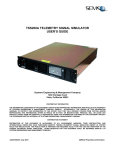
output rating. This component is not included in the following diagram, but will be
discussed in detail in the relays section of this paper.
Figure 8 shows the interfacing within the main control unit. It also specifies the
type of connection used and the number of wires required for each connection
type.
Main Control Unit Interfacing
Figure 8 Main Control Unit interfacing
The dsPIC33FJ256GP710A can connect to 2 UART, 2 I 2C, and 2 SPI modules.
As the diagram shows, both the ZigBee and the 802.11b chips connect via SPI,
the SHT21 temperature and humidity sensor connects via I2C, and the 7”
Evervision LCD touch screen connects via Serial interface that will consume one
of the two UART connections.
After considering all of the necessary
connections, we see that both of the I2C connections will be used, one of the two
SPI connections will be used, and one of the two UART connections will be used.
There will be one SPI and one UART connections left floating in the design of the
main control unit. The dsPIC33FJ256GP710A will be programmed in the C high
level language using the MPLAB C Compiler from MicroChip.
29
2.3 Secondary Microcontroller
For the secondary microcontroller for the system, we needed a simple and very
low power consuming component. This secondary microcontroller will be battery
powered as connecting to a permanent power source is not the end goal for the
system. The secondary microcontroller will interface with the sensors and
802.15.4 ZigBee wireless chip. We have chosen to use the PIC24F04KA201, 20
Pin general purpose 16 Bit flash microcontrollers manufactured by Microchip®.
2.3.1 General Description and Pin Layout
The secondary microcontroller (PIC24F04KA201) has the operation range,
central processing unit (CPU), I/O, Analog-to-Digital Converter and other general
characteristics as follows:
Operation Range:
The operation range of this microcontroller is close to the industry standard. A
supply voltage is needed to run the microcontroller. Since this microcontroller is
going to be attached with the sensor and ZigBee devices, and powered by a
battery, it needs to be low powered like those components. This whole subsystem of the secondary microcontroller will be battery powered, and have the
low supply voltage is essential to our design specifications and keep between the
temperatures of -40˚C and 85˚C. The PIC24F04KA201 features new nanoWatt
XLP (eXtreme Low Power) technology for the low power consumption required in
our system.



Supply Voltage of 1.8 V – 3.6 V
nanoWatt XLP
-40˚C - 85˚C
The PIC24F04KA201 is also equipped with power saving technology such as
On-the-Fly Clock Switching, Doze mode, and Instruction-based power saving
modes. PIC24F devices have two special power-saving modes, entered through
the execution of a special PWRSAV instruction. The Sleep mode halts all code
execution; Idle mode halts the CPU and code execution, but allows the
peripheral modules to continue operation, such as the ZigBee and temperature/
humidity sensor. Deep Sleep mode stops clock operation, code execution and
peripherals. It also freezes the I/O states and removes power to the SRAM and
Flash memory. Combinations of these methods can be used to tailor our
applications power consumption by selectively managing clocking to the Central
Processing Unit (CPU)
CPU Characteristics:




Up to 16 MIPS
C complier optimized instruction set
Modified Harvard architecture
16-bit wide data path
30


4 Kbytes Flash Program Memory for storing and executing application
code
512 Bytes RAM data memory
The microcontroller is also capable of up to 16 MIPS (Millions of Instructions Per
Second), which is standard for a microcontroller of this size and power. The
microcontroller is optimized to be programmed in the C language, the preferred
programming language of the group. The secondary microcontroller will be
responsible for taking in the data from the SHT21 sensor. The 16-bit wide data
path will be sufficient for process the temperature and humidity data, and then
passing the information along to the main microcontroller via the 802.15.4 ZigBee
device.
The internal flash program memory for a device is used for storing and executing
application code. The 4 Kbytes of Flash memory will hold our programming
code, and allow the program to be modified in the future should more features be
added to the system. The memory is readable, writable and erasable when
operating with a VDD over 1.8V. 512 Bytes of RAM will allow is low data rate RF
module to run quickly and effectively.
The secondary microcontroller has 18 I/O pins that can be programmed to work
with other devices such as the sensor and the ZigBee RF transceiver. This
number of I/O pins is above the required number for our design, in case
expansion of the system is needed. The microcontroller also has ADC modules
to transfer input analog voltages into a digital number proportional to the input
voltage or current.
I/O Characteristics:




18 Input/ Output (I/O) pins
Analog-to-Digital Converters
10-bit A/D Convert
9 Analog-to-Digital (ADC) input channels
The SPI module protocol will interface the secondary microcontroller with the
ZigBee wireless chip. The I2C™ module protocol will be used to interface the
temperature and relative humidity sensor with the PIC24F04KA201
microcontroller. The I2C™ module supports both Master and Slave modes of
operation, useful for the sensor connection. The secondary microcontroller block
diagram in Figure 9 below illustrates the peripheral connection with the different
components.
Three Serial Communication Peripherals:



1 – SPI module
1 – I2C™ module
1 – UART module
31
Secondary
Microcontroller
I2C Interface
SPI Interface
MRF24J40MB
PIC24F04KA201
ZigBee Wireless
Transceiver
Secondary
Microcontroller
SHT21
Temperature and
Relative Humidity
Sensor
Power
Battery
Ground
Figure 9 Secondary Microcontroller Interfacing
2.4 Relays
Heating, Cooling, and Air Circulation is accomplished with the help of relays that
act as switches to turn on and off these systems. The relays are triggered by
digital logic as a result of readings from temperature and humidity sensors. In all
of the relays that we have encountered in our research the one that would be
best be suited for our design is a normally closed switching electronic relay. In
the HVAC control we will use relays to activate the output to the heating, air
conditioning and air circulation in response to changes in inside and outside air
temperature depending on the settings selected by the user via the LCD touch
screen display.
The main control unit will allow the user to set a specified temperature and
humidity comfort setting. The NC (normally - closed) relay will be closed and
activate the specific circuit, or opened to deactivate the circuit in order for the
temperature and humidity to be achieved. The tolerance and range of the
temperature and humidity sensors will have a direct affect on the output of the
relays and the activation or deactivation of each of the three systems.
32
Some important factors when choosing the best relay to purchase for the HVAC
control system are:








Affordability, whether it is cost efficient for your budget in designing an
HVAC system
Contact configuration: Single Pole Single Throw, Single Pole Double
Throw, Double Pole Double Throw, Three Pole Single Throw, Four Pole
Single Throw, or Four Pole Double Throw
Coil voltage, how much voltage do you want the coils of the relay to
operate at from the available supply source in order for it to switch the
Heating, Cooling, and Air Circulation as a result of the measured
temperature and humidity.
Type of mounting preferred: Usually surface mounting requires a soldering
iron, socket mounted for plugging into a circuit board for easy
replacement.
Contact protection: This involves the relay‟s contacts that, due to arching
wear over time. Contact protection is the number one concern and priority
in relays. Relays that use relatively small contacts for the voltage and
current in an inductive circuit will result in arching and excess wear over
time.
Low Power Consumption: Low voltage relay coils are less dangerous to
persons working with them, easier to install and do not come under the
stricter codes that apply to wiring over 30 volts.
Max voltage sink by microcontroller: Depending on your microcontroller of
choice, there is a maximum voltage that the I/O pins can produce.
The voltage produced by the microcontroller determines how the buffer
circuit must be set up so that the relay receives the correct voltage and
current.
In typical HVAC control systems there are two types of relays involved. These
relays are the control relays and the power relays. The control relays are
switched on by the main control unit when a decision to turn their specific
component on has been made. The output of each control relay is 24V AC, and
is known as the control voltage. This control voltage is the input to the next relay
which is the power relay. There is typically a power relay located outside at the
compressor and another located at the inside air handler. When the power relay
is switched to the on position, 220/240V AC is connected to the compressor or
air handler and it runs until the main control unit determines it is time to stop and
the relay is switched back to the off position. Figure 10 below is shown to better
illustrate this system.
33
Figure 10 Typical HVAC relay setup
Researching different types of relays led us to come across the website:
http://www.deltrol-controls.com/. This website is pretty good because deltrolcontrol is a leader in the design and manufacturing of electronic components.
They also have very detailed and well explained part specification sheets that list
what type of relays are used for certain applications. The relay that our group is
interested in is the 263/268 series relay. These relays can either be surface
mounted by using a soldering gun or can be directly plugged into the circuit
board. Both the 263 and 268 series relay can carry a maximum of 15 Amps as
well as have an ambient AC temperature ranging from -45 degrees to 65 degrees
Celsius. Our HVAC control system will have multiple different sets of relays; one
relay to activate 1st Stage Heating, one for 2nd Stage Heating, one for Blower /
Fan, one for Compressor, one for Reversing Valve, and one for 24V Common.
The 268 series relay is readily available with a 24V AC coil having a DPDT
configuration that meets our systems requirements. The 24 V AC coil has an
electronic tolerance of ± 10% ranging above or below 72 ohms. It also has a
nominal coil powered at 2.2 VA.
Another consideration when researching relays is how to interface them to the
microcontroller. This involves designing a circuit that uses a transistor to ensure
34
the relay receives the correct current and voltage. Another option for this step is
to use a relay driver which is a surface mount chip with several transistor circuits
inside. The advantage of this type of device is that the design is simplified
because the designer does not have to implement multiple complex circuits into
the design of the printed circuit board. This will be discussed further in the Relay
subsection of the Design portion of this paper.
2.5 LCD Touch Screen
For the Efficient HVAC Control and Feedback System, system navigation and the
user inputted settings can be achieved via the touch display or touch screen
feature. Many electronic appliances now use touch screen displays such as
laptops, palm pilots, blackberries, and music players. These devices all utilize a
touch screen sensor, a controller, and software driver. The various touch display
technologies that are available today are resistive touch screen, surface acoustic
wave technology, and the capacitance touch display panel. All of these touch
display technologies are touch sensors which normally have an electric signal go
through the layers of the screen causing the a voltage to change. The voltage
change will directly link to help telling it the location of the finger touching the
screen.
In the resistive touch screen system, it primarily contains two electrically
conductive layers separated by a narrow gap called a spacer. A current flows
through the two layers of the touch display screen while the monitor is still
running. This system is composed of a glass panel and when the finger is
pressed down on it, it will lock on that exact point in the x-y coordinate plane.
The concept of the voltage divider is used to calculate the x-y coordinate that has
been touched. When the electric field in the touch screen system is changed, the
software driver translates the touch information to the operating system so the
location of the touch can be identified. Figure 11 below includes a step by step
process as to what occurs in a resistive touch screen system.
Figure 11 Resistive touch screen (Reprinting Permission Requested from
3M Touch)
35
The surface acoustic wave technology features two transducers so that when the
panel is touched it can find the coordinate accordingly. These transducers are
positioned on the x and y axes of the coordinate plane of the screen‟s insulated
plate. The controller calculates the time at which the height of the acoustic wave
falls to determine the x and y coordinates position on the x-y coordinate plane.
This technology can also figure out how much pressure is applied to by the
screen. The Z axis (is going into the screen) will determine this depth information.
Once the touch screen locates the finger touched on the panel it will relay
information to the microcontroller. The surface acoustic wave system has the
best image graphics on the screen because 100% light is transmitted. There are
no metallic layers on the screen to block light from going through it. Figure 12
pictured below undergoes the surface acoustic wave touch screen technology
process.
Transducers emit
sound waves
along sides
Sensor
Sound wave
reflector
Controller measures
wave amplitude changed
to determine touch
location
Touch absorbs some
acoustic energy form
sound waves
Figure 12 Surface Acoustic Wave touch screen (Reprinted with Permission
from 3M Touch)
The capacitive touch screen system stores an electrostatic charge while placing
your finger on the glass insulated panel. The electrostatic charge is displaced
when the user places their finger on the monitor. Therefore the capacitive layer is
reduced. An advantage of the capacitive touch screen system is that it sends
90% of light from the monitor to give the screen a crisper and clearer picture than
the resistive system. Figure 13 is a detailed overview as to what happens in a
capacitive touch screen display.
36
Continuous imaging of
touch profile
Image processing
controller
Image of changes in
electrostatic field caused
by touch
Touch screen
(sensor)
Coordinates feed back to
operating system
Controller resolves touch
profile to actual touch point
Figure 13 Capacitive touch screen (Reprinting Permission Requested from
3M Touch)
To differentiate all three different varieties of touch screens, the resistive touch
technology is the cheapest to purchase on the market whereas its graphics and
quality are the worst out of all of them. The next touch screen is the capacitive
touch screen and ranks in the middle in terms of cost. According to consumers
who purchase touch screen displays these are the most reliable and most
popular electronic applications on the market. Finally the surface acoustic wave
technology is the most expensive touch screen with the best picture clarity, pixel
resolution, and longer durability. Some of these touch screen technologies have
gloves to allow the user to use the screen numerous times without scratching or
damaging the glass. Even without gloves some of these technologies use special
protective coating on the glass filament layers. Table 5 shown below compares
the discussed touch screen technologies.
Technology
Resistive (4 Wire
or 5 Wire)
Surface Acoustic
Wave (SAW)
Capacitive
Transparency
75 - 85 %
85 – 92 %
85 – 92%
Accuracy
Low
Low
Moderate
Resolution
High
High
High
Touch / Input
Methods
Anything
Finger or Stylus
Finger
Durability (How
long do they
3 years for 4 Wire
5 years
2 years
37
last?)
5 years for 5 Wire
Cost
Inexpensive
Expensive
Average cost
Sensitivity
Very sensitive to
scratch
Sensitive to
scratch
Sensitive to dirt
Advantages
Inexpensive, can
detect any object,
not sensitive to
water, humidity or
dust
Can be used on
curved surface,
not sensitive to
water
Average cost,
scratch resistant,
not sensitive to
humidity or
temperature
Disadvantages
Sensitive to
scratch, low
fidelity, and
reduce visibility of
the touch screen
Very expensive,
sensitive to
scratch
Can only use your
finger, reduces
illumination, can‟t
move your finger
(so it can be able
to detect it for
position)
Color Fidelity
Low
Low
Low
10 ms
Less than 15 ms
For 4 wire: Less
than 10 ms
Response time
For 5 wire: Less
than 15 ms
Installation
Built - in or Onwall
Built - in
Following Speed
Good
Low
Good
Stability
High
Best stability out
of all 3
Ok
Light Resistant
Good
Good
Bad
Table 5 Touch screen technology comparison
Next on the list of components for a touch screen display is the controller. The
two controller configurations used are the ISA Bus and the Serial RS232. ISA
Bus controllers are limited only to a printed circuit board. The serial controllers
are built on printed circuit boards and are surface mounted using a soldering gun.
These different types of controllers are basically PC cards that attach the touch
sensor to the PC. It holds information from the touch sensor and relays the
information to the PC so it can understand it better.
Finally the software driver is an essential part in the HVAC system control that
we will be developing for the Efficient HVAC Control and Feedback System. The
38
driver will permit the touch screen and the computer to work together. The most
commonly used touch screen driver is the mouse-emulation type driver which
functions the same way as clicking the mouse at the same place on the screen.
The touch screen can coexist together with existing software and will permit new
technological applications to occur without the need for programming.
Another concept that a person needs to be aware of when trying to determine
what would be the best touch screen panel is to know what an NIT is. Candelas
per meter square is a measurement of light in the determining the brightness of a
touch screen display panel. Candelas per square meter is often referred to as an
NIT and this is equal to footlamberts * 3.43. Below are some formulas used to
figure out touch screen illumination, screen brightness, and total light outputted
from the screen:




A vital term that becomes important when considering touch screen displays is
the contrast ratio (CR). The contrast ratio is defined as being the proportion of
luminance to white and dark light that is formed on a touch screen display. This
takes place when figuring out the best picture quality between the various touch
screen displays: resistive touch screen, surface acoustic wave, and capacitive
touch screen. To have an enhanced sharp picture, a user must purchase a touch
screen with a high contrast ratio. The contrast ratio changes when measuring the
ambient illumination in a dark room compared to the touch screen being
calculated outside in the sunlight.
Last of all is the viewing angle terminology. A viewing angle for a touch screen
display is the angle at which the pixel resolution and image quality gets bad
enough and unacceptable for the user to view. In order for the viewing angle to
degrade on the touch screen it will go through three processes. The first course
goes through a drop in luminance or luminous flux. Next the contrast ratio will fall
at large angles and as a result the pixel or resolution colors on the touch screen
may start to deviate. Criteria based on viewing angles consist of the luminance
and contrast ratio.
2.6 Wireless Interfacing
One of the most important features for our HVAC design is to be able to
communicate wirelessly between the different components. The feedback and
control system will not use wires to connect the subsystems like the secondary
microcontroller and the main control unit. Wireless components are making
industries and systems like HVAC units easier to install, operate and fix as
wireless technology is becoming easier and more reliable to implement.
39
2.6.1 Ethernet and Wireless Routers
Ethernet is a branch of wired technologies under the Local Area Network
communication. Ethernet‟s standard practice used is the 802.3 which has been
created since the 1980‟s. Changes have occurred in the recent years to make
the Ethernet have higher bandwidth quality and improved media access control
methods. The standard connector used to connect the Ethernet port from the
computer to the Ethernet jack in the wall is called the RJ45 connector. This
connection is used in most home computers where it is an alternative way to
obtain internet access. In our system, we will have the Ethernet connection with
the wireless router to provide the network on which our wireless technology will
be able to connect to the Internet.
The system also needs to include a wireless method for connecting the smart
phone application with the main control unit. The use of a wireless router allows
our system to establish a network so that the smart phone can communicate with
the main control unit. Wirelessly routers connect the devices to the Internet
through the use of wireless chips embedded inside. The smart phone application
will be able to access the feedback and control system features anywhere,
whether it is inside the house included in the range of the wireless router, or out
on the wireless networks in virtual every corner of the nation.
Wireless routers that will be considered for use and purchase are either going to
be the 802.11g router or the 802.11n router. The n router has faster signal
strength than the g router with double the range. Other factors in considering the
n router vs. the g router is that n routers cost more but are backwards-compatible
meaning that n routers can still transmit data as g routers. In the 21 century the
wireless g routers is a fading technology they are being replaced with wireless n
routers.
An application can be developed for smart phones that simulate the control
panels display screen right on the smart phone. With the smart phone you can
access and control the comfort features from anywhere while connected to the
internet. While designing the smart phone application, connection speed is a
concern as we want real time data from the system and the ability to make
changes to the system.
2.6.2 Wireless Protocols
One of the main features of our system is having the different components
communicating wirelessly. The sensors recording temperature and humidity data
are going to report that data back to the main microcontroller, so that the correct
decision can be made to chose the most effective option for the desired settings.
The main microcontroller also has to be able to connect to the internet wirelessly,
for viewing and controlling for the end user. Additionally, once the system makes
a decision based on the settings the user has set, a signal will be sent to the
40
relays controlling the different heating and cooling options so that the appropriate
action can be carried out.
The question becomes which form of wireless technology will be most effective
for caring out these decisions and actions. With so many different choices of
wireless communication, certain key features must be accounted for and
analyzed before we can select the best option. The three biggest options in the
wireless technology field that can give us a better understanding are: Bluetooth,
ZigBee and Wi-Fi®. Each of these wireless protocols have pros and cons that
will help us choose the best communication system for our components. The
sections following outline and describe these communication protocols.
2.6.3 IEEE 802.15.4 – ZigBee
ZigBee is a specification for a suite of high-level protocols using small, lowpowered digital radios based on IEEE 802.15.4 standard for low-rate wireless
personal area networks (LR-WPANs). The 802.15.4 protocol offers the lower
network layers of wireless personal area networks (WPANs) which are focused
on the simple, low-cost, low-power consumption, simultaneous communication
between devices. ZigBee is targeted for radio-frequency applications that require
low data rate, a long battery life, and secure mesh networking. Mesh networking
provides high reliability with a more extensive range. The low cost of the ZigBee
protocol allows the technology to be widely deployed in wireless control and
monitoring applications and the low-power usage allows for longer life with
smaller batteries. ZigBee is less expensive and simpler to operate compared
with other WPANs like Bluetooth.
The ZigBee wireless standard is a great option for this project. An external
ZigBee device could interface with both our main and secondary microcontroller.
Many microcontrollers‟ have ZigBee transceivers already built in; saving space
on our printed circuit board (PCB). Other house appliances like the home
telephone, microwave, Wi-Fi and Bluetooth share the 2.4 GHz ISM band,
causing noise for the ZigBee device. ZigBee has low data rates, meaning that
less data needs to be transmitted, making the noise a non factor for the system.
The low power physical layer of the ZigBee allows the ability to transmit of a
range up to 75 meters, which is more than enough for the scale of this project.
Another great fact is that for an individual device to pass the ZigBee certification,
it must have a battery life of at least two years, proving how low power ZigBee
communication is. Table 6 pictured below illustrates the pros and cons of the
zigbee wireless standard protocol.
41
Pros
Cons
Transmission range between 10 – 75
meters (33 -264 feet) and up to 1500
meters for ZigBee pro
On the cluttered 2.4 GHz ISM band
Maximum output power is generally
0dBm (1mW)
Low data rates up to 720 kbits/s
Easily implemented
Flexible network structure
Small size
Individual devices must have batter life
of at least two years
Many manufacturers are integrating
microcontrollers with ZigBee
transcievers
Table 6 Pros and Cons of ZigBee
ZigBee has many appealing features, extremely low power, great battery life, and
a good transmission range. These features make a ZigBee device a great choice
for our secondary microcontroller to communicate with the other devices. The
secondary microcontroller will send very low data rates, need to be battery
powered for a longer life, and need to communicate with the main
microcontroller. All of which can be handled by the ZigBee technology.
2.6.4 Bluetooth
Bluetooth was another option to consider for wireless technology that could work
in exchanging data in our system. Bluetooth is an open wireless protocol used
for exchanging data over short distances from fixed and mobile devices. This
creates personal area networks (PANs). This technology was originally designed
as a wireless alternative for RS232 data cables. It could connect several devices
at the same time overcoming synchronization problems. Many small electronic
devices utilize Bluetooth as an alternative to wires.
Using radio technology called frequency-hopping spread spectrum, Bluetooth
can chops up the data that is being sent and transmits chunks of it on up to 79
frequencies. It can achieve a gross data rate of 1Mbps for Bluetooth 1.0, 1-3
Mbps for Bluetooth 2.1 and 54 Mbps for Bluetooth 3.0. Bluetooth operates and
exchanges information through the secure, globally unlicensed Industrial,
scientific, and medical (ISM) 2.4 GHz short range radio frequency (RF) band.
There are three classes of Bluetooth: Class 1 uses up to 100mW of power and
can transmit approximately 100m, Class 2 uses up to 2.5mW of power and can
42
transmit approximately 10m and Class 3 uses up to 1mW of power and can
transmit approximately 1m.
Like any protocol, there are drawbacks and problems with Bluetooth. Bluetooth
has problems with wall penetration, which is a major concern for our system.
Bluetooth also uses more power for the distance the data is traveling compared
to ZigBee. Another drawback is that other house appliances, like wireless home
telephone, ZigBee and Wi-Fi signals clutter the 2.4 GHz ISM band. This could be
a problem when dealing with noise corrupting packets of data being sent. The
Bluetooth protocol has a way to deal with this type of interference and limiting
those problems. Users using Bluetooth must also initiate a pairing between the
devices initial, making more work later for the end user. Overall though, it looks
like using the Bluetooth protocol is not the best solution for our system.
2.6.5 IEEE 802.11 – Wi-Fi
IEEE 802.11 (Wireless Local Area Network) protocol is the most widely used and
recognized computer related wireless communication system. The term Wi-Fi ®
is a registered trademark of the Wi-Fi Alliance ® and is often used as a synonym
for IEEE 802.11 technology. This protocol has been constantly upgrading and
developing since its release in 1999. The availability of Wi-Fi® microchips for
embedded devices along with its wide range of use makes IEEE 802.11 an
excellent option to consider for our system. The 802.11 protocol has a few
network standards that are compared in Table 7 below.
802.11
Protocol
Release
Frequency
(GHz)
Bandwidth
(MHZ)
Approx.
range
indoors
(meters)
Approx.
range
indoors
(feet)
-
June 1997
2.4
20
20
66
a
Sept.
1999
5
20
35
115
b
Sept.
1999
2.4
20
38
125
g
June 2003
2.4
20
38
125
n
Oct. 2009
2.4 / 5
20 / 40
70
230
Table 7 802.11 Network Standards
Before determining if Wi-Fi® is the way to go, we must first analyze the
capabilities of Wi-Fi® to see if it will meet the requirements of our project. Some
of the capabilities of Wi-Fi® include excellent range. The IEEE 802.11 b
protocol‟s typical range of 38 m (125ft) is more than enough distance required by
our system. 802.11 b also has throughput up to 11 Megabytes per second
43
(Mbps), which is overkill for our system. By adjusting throughput to 1 Mbps, we
can extend the indoor range from 30 meters, to 90 meters, which is again more
than enough for our system. Additionally, Wi-Fi® has many security measures in
place, such as Wi-Fi Protected Access (WPA, WPA2) and Wired Equivalent
Privacy (WEP) encryptions to protect the wireless networks security.
After analyzing the capabilities of IEEE 802.11 b Wi-Fi®, it is clear that this
method is perfect for meeting the system‟s requirement of connecting to the
internet wirelessly. With an internet connection, data can be exchanged and the
user will have access to the system and the settings, and can monitor and control
the system.
Bluetooth, ZigBee and Wi-Fi® are all excellent forms of wireless communication.
With so many pros and cons of each, choosing the correct method for optimal
performance is essential. Table XX below outlines the wireless methods. For the
requirement of the secondary microcontroller wirelessly communication, the
802.15.4 ZigBee protocol is the ideal choice. And for the main microcontroller‟s
connection to the internet, 802.11 b Wi-Fi® is an excellent choice. Table 8 shown
below outlines key features of the wireless protocol.
Wireless Protocols
Bluetooth
(Class 1)
ZigBee
(802.15.4)
Wi-Fi®
(802.11 b)
Optimal Range (indoor):
~100 meter
10 – 75 meters
30 meters
Frequency Band:
2.4 GHz ISM
band
2.4 GHz ISM
band
2.4 GHz ISM
band
Communication type:
WPANs
PANs
WLAN
Power required to
operate:
100mW
1mW
100mW
Cost of implementation:
Low Cost
Low Cost
Medium Cost
Bandwidth:
1 Mbps
0.250 Mbps
11 Mbps
Encrypted:
Yes
Yes
Yes
Primary Use:
Data exchange
over short
distances
Small, low
powered
devices
Mobile
Internet
Table 8 Wireless protocols key features
Now that we have selected the wireless methods and protocols that are capable
of completing the necessary tasks required, finding the appropriate wireless
module chips is the next step. The wireless module for connecting the main
microcontroller to the internet must have some basic requirements which are
listed below in Table 9. For the secondary microcontroller to communicate with
44
the main microcontroller through the ZigBee method, it too must have some
basic requirements, which are also listed below in Table 9.
Main Microcontroller Wireless
Module Requirements
Secondary Microcontroller Wireless
Module Requirements
Low power consumption
Easy integration to the system
Small size and surface mountable
Have security protocols
Low current consumption
Wi-Fi® certified
Different modes for different uses
Low current consumption
Handles low data rates
Different modes for different uses
Excellent range
Excellent range
Table 9 Main and Secondary microcontroller wireless module requirements
Microchip‟s® Wireless Design Center (http://www.microchip.com/wireless) was
an excellent resource when searching for wireless solutions for our project. The
MRF24WB0 Wi-Fi module product family meets the requirements for connecting
the MCU to the internet for our project. The MRF24WB0MA has an integrated
PCB antenna, while the MRF24WB0MB has an external antenna option with an
ultra miniature coaxial connector for extended range. For the scope and
requirements of this project, having the integrated PCB antenna instead of an
external antenna will make for a smooth implementation into the embedded
system. The MRF24J40 ZigBee module product family meets the secondary
microcontroller requirements for communication of the different devices in our
system. Both MRF24J40MA and MRF24J40MB modules have an integrated
PCB antenna, the only difference is that MRF24J40MA has a 400 ft range, while
the MRF24J40MB has a range of 4000 ft. Have that extended range makes
MRF24J40MB a great choice for our ZigBee wireless module. In the sections
below, are detail specifications about each of the two wireless chips from
Microchip®.
2.7 Smart Phone Application
2.7.1 Remote Access
The purpose of having remote access in the Efficient HVAC Control and
Feedback System is to provide the end user instant feedback and control of the
system. This is a key feature of the overall system. This is important because
the number of people with internet ready mobile devices is constantly growing.
45
This means there is a huge market for applications to allow consumers to access
and manipulate their home or office appliances and HVAC systems while away
from the building. This also ensures optimum settings to save energy and money
when the user is away from the building. Below is a discussion on how such a
system would be implemented in order to provide remote access.
2.7.2 TCP/IP
The Internet Protocol Suite, or TCP/IP, is a set of communication protocols used
for the Internet. A TCP/IP will be required to connect our system to the internet.
This abstraction allows encapsulation of the data as it travels from one layer to
the next. Each layer uses a set of protocols to send its data down the layers,
being further encapsulated at each level. This suite is constructed as a set of
layers as seen in Figure 14 below.
Figure 14 Layers of the TCP/IP reference model
2.7.3 Host-to-Network Layer
This layer interfaces the higher layer protocols to the local network. This layer is
primarily representative of the physical connection between two devices and
often does not run any TCP/IP protocols as they are simply not needed. Its
primary functions are to provide logical link control (LLC) and Media Access
Control (MAC). LLC refers to the functions required to establish and control
logical links between local devices on the network. Most LAN devices use the
IEEE 802.2 LLC protocol. MAC refers to the methods used by devices to control
access to the network medium. Since most networks use devices that share a
medium, it is necessary to have a rule set in place to manage the connection to
avoid collisions. One example is that Ethernet uses CSMA/CD while Token
Rings uses token passing. In addition to the two different control methods used,
this layer is also responsible for the final encapsulation of higher-level messages
into frames that are sent over the network; with the frames in place, the Host-toNetwork layer must also manage the address of the receiving device. Finally the
Host-to-network Layer is also responsible for error detection and handling.
46
2.7.4 Internet Layer
The Internet layer helps define how interconnected networks function. This layer
is the lowest layer concerned with devices that are located on a remote network,
where as the Host-to-Network layer was only concerned about locally connected
devices. In order to communicate with remote networks, the Internet layer
provides logical addressing via Internet Protocol (IP). These are logical
identifiers (not physical identifiers like MAC at the Host-to-Network layer) and
they must be unique over the entire internetwork. To move data across a series
of interconnected networks, the Internet Layer provides routing. Devices and
software that function at this layer provide functionality to handle incoming
packets from various sources, determine their final destination, and then figure
out where they need to be sent to get them where they are supposed to go. The
data at this layer gets encapsulated into messages called datagrams with a
network layer header. In order to send this information down to the Host-toNetwork layer, the Internet Layer must also handle fragmentation and
reassembly of datagrams to fit within the size limitations of the lower layer.
2.7.5 Transport Layer
The overall job of this layer is to provide the appropriate functions to enable
communication between software application processes on different computers.
This layer is also called the host-to-host transport layer as it is responsible for
that exact function. To transmit, the layer keeps track of what data arrives from
each application, then combines the data into a single flow to send to the lower
layers. On the receiving end, the operation is revered, splitting the data and
funneling it to the appropriate software process.
Another function of this layer is to provide connection services for the protocols
and applications that run at the application layer. In order to determine which
process will receive a specific price of data requires a process-level address.
This is defined using port numbers within TCP/UDP packets. Each application
uses a specific port for receiving and transmitting information that gets
encapsulated into outgoing packets. When a receiving device receives a packet,
it can see what destination port it was being sent to and will provide the data to
the processes assigned to that port.
In addition to providing host-to-host services, the Transport Layer must also be
able to acknowledge received data and be able to retransmit information when it
is lost. Each time data is sent, a timer is started; if it is received, the recipient
sends back an acknowledgment to the transmitter to indicate a successfully
received packet. If the timer runs out, the data is retransmitted. In order to make
sure that the sender and receiver send and receive packets efficiently, this layer
is also taxed with flow control. This allows a device to specify to another that it
must throttle back the rate at which it is sending the information.
47
2.7.6 Application Layer
The application layer is that which network applications operate at. Applications
that operate at this layer are, for example, HTTP, FTP, SMTP, DHCP, NFS,
Telnet, SNMP, POP3, NNTP and IRC. The function of this layer is that it
provides services to programs that want to use the network and to issue the
appropriate commands to properly use the services provided by the lower levels.
2.7.7 Microchip TCP/IP Stack
Microchip provides a freely available TCP/IP stack for use with their
microprocessors. Figure 15 below shows how it is implemented and compares it
to the TCP/IP Reference Model.
Figure 15 Comparing the Microchip TCP/IP stack structure to the TCP/IP
reference model (Reprinted with Permission from Microchip)
Unlike the Reference model, some layers in the Microchip TCP/IP Stack have
direct access layers which are not immediately below it. The decision for when a
layer would bypass its adjacent module was made based on the amount of
overhead and whether a given service needs intelligent processing before it can
be passed to the next layer or not.
With Microchip‟s design, they depart from traditional TCP/IP Stack
implementation by adding StackTask and ARPTask. StackTask manages the
operations of the stack and all of its modules, while ARPTask manages the
services of the Address Resolution Protocol Layer.
Microchip‟s TCP/IP stack is a live stack; some of the layers must be able to
perform timed operations asynchronously. To meet the requirement, Microchip‟s
48
TCP/IP Stack uses a multitasking technique called cooperative multitasking. In a
cooperative multitasking system, there is more than one task; each performs its
job and returns its control so that the next task can perform its job. StackTask
and ARPTask are cooperative tasks.
Normally cooperative multitasking is implemented in the operating system or in
the main application, but with Microchip‟s design, it is independent of any
operating system; it implements its own cooperative multitasking system. This
allows it to be used in any system, regardless of whether it uses a multitasking
operating system or not. In order to use an application utilizing the Microchip
TCP/IP Stack, it must be written using a cooperative multitasking method. This
can be accomplished by either dividing the job into multiple tasks, or organizing
its main job into a Finite State Machine and dividing a long job into multiple
smaller jobs.
2.7.8 Implementation
In order for the TCP/IP stack to function, you must use C compiler “defines” to
configure to program. In order for the server to operate properly, the clock
frequencies need to be configured. Those options are found within the Tick.C
file. Table 10 below describes the purpose of each of those configurable values.
Define
Values
Purpose
Oscillator
Define system oscillator
CLOCK_FREQ
Frequency
frequency to determine tick
(compiler.h)
(hz)
counter value
TICKS_PER_SECONDS
10-255
To calculate a second
2, 4, 8, 16, 32,
TICK_PRESCALE_VALUE
To determine tick counter value
64, 128, 256
Table 10 Configuration used by Tic C
The file system needs to be configured to know where to look for an image.
These configuration options can be located in MPFS.c. Table 11 below contains
a description of each of those values.
Define
Values
MPFS_USE_PGRM
N/A
MPFS_USE_EEPROM
N/A
MPFS_RESERVE_BLOCK
0-255
EEPROM_CONTROL
External Data
EEPROM
Control Code
49
Purpose
Uncomment this if program
memory will be used for MPFS
storage
Uncomment this if external
serial EEPROM will be used for
MPFS storage
Number of bytes to reserve
before MPFS storage starts
To address external data
EEPROM
MPFS_WRITE_PAGE_SIZ
E(mpfs.h)
1-255
To define writable page size for
current MPFS storage media
Table 11 Configuration used by MPFS.C
StackTsk.c manages the operations of the stack and its modules. Which
modules you enable are defined within the configurable defines. The values
related to StackTsk.c are provided in Table 12 below.
Define
STACK_USE_ICMP
STACK_USE_IP_GLEANI
NG
STACK_USE_DHCP
STACK_USE_FTP_SERV
ER
Values
N/A
Purpose
Comment this if ICMP is not required
Comment this if IP Gleaning is not
N/A
required
N/A
Comment this if DHCP is not required
Comment this if FTP Server is not
N/A
required
Comment this if TCP module is not
required. This module will be
STACK_USE_TCP
N/A
automatically enabled if there is at
least one high-level module requiring
TCP.
Comment this if UDP module is not
required. This module will be
STACK_USE_UDP
N/A
automatically enabled if there is at
least one high-level module requiring
UDP.
STACK_CLIENT_MODE
N/A
Client related code will be enabled
Table 12 Configuration used by StackTsk.c
TCP.c provides the operation of all the transport host-to-host operations. This
includes managing sockets and confirming ACKs on packets sent. Table 13
below is a table with the configurable options that this file relies on.
Define
TCP_NO_WAIT_FOR_AC
K
Values
MAX_SOCKETS
1-253
MAX_TX_BUFFER_SIZE
201-1500
STACK_CLIENT_MODE
N/A
STACK_USE_TCP
N/A
N/A
50
Purpose
TCP will wait for ACK before
transmitting next packet
To define the total number of
sockets supported (limited by
available RAM). Compile-time
check is done to make sure that
enough sockets are available for
selected TCP applications.
To define individual transmit
buffer size
Client related code will be
enabled
Comment this if TCP module is
not required. This module will
be automatically enabled if there
is at least one high-level module
requiring TCP.
Table 13 Configuration used by TCP.c
User Applications have access to default network setting values as well as
access to actual network setting values. Default values are defined within the
configuration, whereas the actual values are saved by applications that are
currently running. Below is Table 14 which provides a list of definitions and the
values they can be.
Define
MY_DEFAULT_IP_ADDR_B
YTE?
MY_DEFAULT_MASK_BYTE
?
MY_DEFAULT_GATE_BYTE
?
MY_DEFAULT_MAC_BYTE?
Values
Purpose
0-255
Define default IP, MAC, gateway
and subnet mask values.
Default values are:
10.10.5.15 for IP address
00:04:163:00:00:00:00 for MAC
10.10.5.15 for gateway
255.255.255.0 for subnet mask
Actual IP, MAC, gateway and
subnet mask values as
saved/defined by application. If
0-255
DHCP is enabled, these values
reflect current DHCP server
assigned configuration
Table 14 Configuration used by User Application
MY_IP_BYTE?
MY_MASK_BYTE?
MY_GATE_BYTE?
MY_MAC_BYTE?
UDP.c implements the user datagram protocol. This uses a simple transmission
model without implicit hand-shaking required for guaranteeing reliability, ordering,
or data integrity. Most of these operations are handled by the application utilizing
this protocol. Table 15 below shows the configurable options for this file.
Define
Values
STACK_USE_UDP
N/A
MAX_UDP_SOCKETS
1-254
51
Purpose
Comment this if UDP module is
not required. This module will be
automatically enabled if there is at
least one high-level module
requiring UDP.
To define total number of sockets
supported (limited by available
RAM). Compile-time check is
done to make sure that enough
sockets are available for selected
UDP applications
Table 15 Configuration used by UDP.c
MAC.c handles the Media Access Control operations. This allows for the
emulation of a full-duplex logical communication in a multi-point network. In Table
16 below are the configuration defines that MAC.c uses.
Define
Values
Purpose
To define individual transmit
MAX_TX_BUFFER_SIZE
201-1500
buffer size
To define total number of
MAX_TX_BUFFER_COUN
transmit buffers. This number is
1-255
T
limited by available MAC buffer
size.
Actual IP, MAC, gateway and
MY_IP_BYTE?
subnet mask values as
MY_MASK_BYTE?
saved/defined by application. If
0-255
MY_GATE_BYTE?
DHCP is enabled, these values
MY_MAC_BYTE?
reflect current DHCP server
assigned configuration
Table 16 Configuration used by MAC.c
ARP.c runs the Address Resolution Protocol. This allows the host device to
determine a hardware address from just knowing an IP address. Configuration
values that are used by this module are described in Table 17 below.
Define
Values
Purpose
Client related code will be
STACK_CLIENT_MODE
N/A
enabled
Actual IP, MAC, gateway and
MY_IP_BYTE?
subnet mask values as
MY_MASK_BYTE?
saved/defined by application. If
0-255
MY_GATE_BYTE?
DHCP is enabled, these values
MY_MAC_BYTE?
reflect current DHCP server
assigned configuration
Table 17 Configuration used by ARP.c
HTTP.c controls the webserver to run on the microchip. This module manages
user connections and CGI GET operations. The GET command allows the
webserver to fetch variables saved within the microprocessor and dynamically
present them within a static web page. Table 18 below lists the configurable
options that HTTP.c uses to implement the web server.
Define
Values
MAX_HTTP_CONNECTIO
NS
1-255
52
Purpose
To define maximum number of
HTTP connections allowed at
any time.
To define maximum number of
1-31
HTML form fields including
HTML form name
MAX_HTML_CMD_LEN
To define maximum length of
1-128
(HTTP.c)
HTML form URL string.
Table 18 Configuration used by HTTP.c
MAX_HTTP_ARGS
(HTTP.c)
FTP.c implements a simple File Transfer Protocol application. The purpose of
this is to allow an easy way to upload MPFS image files to the host device. Table
19 below shows the configurable values used by the FTP server.
Define
Values
Purpose
FTP_USER_NAME_LEN(F
To define maximum length of
1-31
TP.h)
FTP user name
STACK_USE_FTP_SERV
Comment this if FTP Server is
N/A
ER
not required
Table 19 Configuration used by FTP.c
DHCP or Dynamic Host Configuration Protocol allows for the auto configuration
of IP address settings. If enabled, this allows the host device to request network
information from a DHCP server. The information received from the server
allows the host device to configure its IP address, net mask, and gateway
information. Table 20 below lists values utilized by DHCP.c.
Define
Values
Purpose
Comment this if DHCP is not
STACK_USE_DHCP
N/A
required
Actual IP, MAC, gateway and
MY_IP_BYTE?
subnet mask values as
MY_MASK_BYTE?
saved/defined by application. If
0-255
MY_GATE_BYTE?
DHCP is enabled, these values
MY_MAC_BYTE?
reflect current DHCP server
assigned configuration
Table 20 Configuration used by DHCP.c
Serial Line Internet Protocol is an encapsulation of the Internet Protocol designed
to work over serial ports. In order to use it within the TCP/IP stack, the module
must be enabled. Table 21 below is a table of values utilized by this module.
Define
Values
Purpose
Comment this if SLIP is not
STACK_USE_SLIP
N/A
required
Table 21 Configuration used by SLIP.c
Once a project is setup with the appropriate files included, the main application
source file must be modified to include the programming sentences shown below
in Figure 16.
53
// Declare this file as main application file
#define THIS_IS_STACK_APPLICATION
#include “StackTsk.h”
#include “Tick.h”
#include “dhcp.h” // Only if DHCP is used.
#include “http.h” // Only if HTTP is used.
#include “ftp.h” // Only if FTP is used.
// Other application specific include files
...
// Main entry point
void main(void)
{
// Perform application specific initialization
...
// Initialize Stack components.
// If StackApplication is used, initialize it too.
TickInit();
StackInit();
HTTPInit(); // Only if HTTP is used.
FTPInit(); // Only if FTP is used.
// Enter into infinite program loop
while(1)
{
// Update tick count. Can be done via interrupt.
TickUpdate();
// Let Stack Manager perform its task.
StackTask();
// Let any Stack application perform its task.
HTTPServer(); // Only if HTTP is used.
FTPServer(); // Only if FTP is used.
// Application logic resides here.
DoAppSpecificTask();
}
}
Figure 16 Mandatory programming sentences
The provided TCP/IP stack is specifically written to utilize the Realtek
RTL8019AS Network Interface Controller. Since the network controller being
used is not that Realtek model, the MAC.c file will need to be modified.
The stack utilized the SRAM on the NIC as a holding buffer, until a higher level
module reads it. It will also perform the IP checksum calculations in the SRAM of
the NIC. This MAC layer also manages its own transmit queue. Using this
queue, the caller can transmit a message and request the MAC to reserve it so
54
that the same message can be retransmitted, if required. The size of this buffer
can be specified.
2.7.9 Microchip HTTP Server
With Microchip‟s TCP/IP Stack comes a minimally implemented HTTP server.
The overburdened HTTP is stripped down to the essential features. The end
user is left to code their own features if more is needed. The HTTP server
incorporates a set of useful features to the user. The list below discusses these
features:







Supports multiple HTTP connections
Contains a simple file system (MPFS)
Supports Web pages located in either internal program memory or
external serial EEPROM
Includes a PC-based program to create MPFS images from a given
directory
Supports the HTTP method “GET” (other methods can be easily added)
Supports a modified Common Gateway Interface (CGI) to invoke
predefined functions from within the remote browser
Supports dynamic web page content generation
2.7.10 Implementation
In order to integrate the HTTP Server into a Suer application, the following must
be done:
1. Uncomment STACK_USE_HTTP_SERVER in the header file
“StackTsk.h” to enable HTTP Server related Code.
2. Set the desired MAX_HTTP_CONNECTIONS value in the “StackTsk.h”
header file
3. Include the files “http.c” and “mpfs.c” in the project
4. Depending where web pages are stored, uncomment either
MPFS_USE_PGRM, or MPFS_USE_EEPROM. If external data
EEPROM is used as a storage media, include the file “xeeprom.c” as well
5. Modify the main() function of the application to include the HTTP server.
The web pages needed to be stored on the server need to be generated in
advance and need to be converted into a compatible format for storage. The
page itself needs to be stored in a format that the server can readily read.
Provided by Microchip is the “Microchip File System” (MPFS). If the storage
space is being provided by EEPROM, the data can be uploaded via FTP. Figure
17 below shows an example of this.
55
Figure 17 Uploading an MPFS Image using FTP
To provide the user with a dynamic page in order to view current system data,
the use of CGI will be needed. With the Microchip HTTP server, the HTTP GET
option is already implemented. When the HTTP server encounters a string „%xx‟
in a CGI page that it is serving, it calls the function HTTPGetVar. The function is
implemented by the main user application and is used to transfer application
specific variable status to HTTP. Figure 18 shown below uses the HTTPGetVar
function to update system data by a CGI.
Syntax
WORD HTTPGetVar(BYTE var, WORD ref, BYTE *val)
Parameters
var [in]
Variable identifier whose status is to be returned
ref [in]
Call Reference. This reference value indicates if this is a very first call. After
first call, this value is strictly maintained by the main application. HTTP uses
the return value of this function to determine whether to call this function again
for more data. Given that only one byte is transferred at a time with this
callback, the reference value allows the main application to keep track of its
data transfer. If a variable status requires more than bytes, the main application
can use ref as an index to data array to be returned. Every time a byte is sent,
the updated value of ref is returned as a return value; the same value is passed
on next callback. In the end, when the last byte is sent, the application must
return HTTP_END_OF_VAR as a return value. HTTP will keep calling this
function until it receives HTTP_END_OF_VAR as a return value.
56
Possible values for this parameter are:
Value
HTTP_START_OF_VAR
Meaning
This is the very first callback for
given variable for the current
instance. If a multi-byte data
transfer is required, this value
should be used to conditionally
initialize index to the multi-byte
array that will be transferred for
current variable
Main application specific value.
For all others
val [out]
One byte of data that is to be transferred
Return Values
New reference value as determined by main application. If this value is other
than HTTP_END_OF_VAR, HTTP will call this function again with return value
from previous call.
If HTTP_END_OF_VAR is returned, HTTP will not call this function and
assumes that variable value transfer is finished.
Possible values for this parameter are:
Value
Meaning
HTTP_END_OF_VAR This is a last data byte for given variable.
HTTP will not call this function until
another variable value is needed.
For all Others
Main application specific value.
Pre-Condition
None
Figure 18 CGI Page Calling the HTTPGetVar Function
With the information provided by the previously introduced function, we are able
to provide real time data from the microcontroller to the user via a dynamically
updating web page. Figure 19 shown below is an example of one such
implementation.
“status.cgi” contains following HTML line:
…
<td>S3=%04</td><td>D6=%01</td><td>D5=%00</td>
…
Figure 19 Dynamically Updated Web Page using HTML code
57
During processing of this file, HTTP encounters the „%04‟ string. After parsing it,
HTTP makes a callback. HTTPGetVar(4, HTTP_START_OF_VAR, &value). In
Figure 20, the main user application implements HTTPGetVar function as
follows:
WORD HTTPGetVar(BYTE var, WORD ref, BYTE *val)
{
// Identify variable.
// Is it RB5 ?
if ( var == 4 )
{
// We will simply return „1‟ if RB5 is high,
// or „0‟ if low.
if ( PORTBbits.RB5 )
*val = „1‟;
else
*val = „0;
// Tell HTTP that this is last byte of
// variable value.
return HTTP_END_OF_VAR;
}
else
// Check for other variables...
...
}
Figure 20 HTTPGetVar Function
2.8 MPFS
The Microchip HTTP server uses a simple file system (MPFS) to store
Webpages. The image of the file system can be stored in on-chip program
memory, or on an external serial EEPROM. Below is Figure 21 which describes
how the MPFS stores multiple files:
58
Figure 21 MPFS Image Format
The length of the Reserved Block is defined by MPFS_RESERVE_BLOCK. This
block can be used by the main application to store simple configuration values.
The storage begins with one or more MPFS FAT entries, followed by one or
more file data. The FAT entry describes the file name, location and its status.
Figure 22 below describes the format for the FAT entry.
Figure 22 MPFS Fat Entry Format
The Flag indicates whether the current entry is in use, deleted, or at the end of
the FAT. Each entry also contains either a 16 or 24-bit address value. The
length is determined by the type of memory used, as well as the memory size
model. If the internal program space is used, and the Microchip TCP/IP stack
project is compiled with a small memory model, 16-bits are used. If the large
memory model is selected, a 24-bit address is used. All EEPROM configurations
use 16-bit addressing. This implies a maximum MPFS image size of 64 Kbytes
for these devices.
MPFS uses a short naming scheme for file name of “8 + 3” (8 bytes for the name,
3 bytes for the extension). The 16-bit address gives the start of the first file data
59
block. All file names are stored in upper case to make file name comparisons
easier.
Each FAT entry points turn to a data block that contains the actual file data. The
data block format is shown below. The block is terminated with a special 8-bit
flag called EOF (End of File. Followed by FFFFh (for 16-bit), or FFFFFFh (24-bit
addressing). If the data portion of the block contains an EOF character, it is
stuffed with the special escape character, DLE. Any occurrence of DLE itself is
also stuffed with DLE. Figure 23 shown below describes the MPFS data block
format.
Figure 23 MPFS Data Block Format
2.9 Mobile Web Site
Mobile web sites allow for specifically designed web pages to load templates
specifically designed for mobile devices. The first access to the mobile web was
offered in Finland in 1996. Since then the trend has caught on. As of October
2009, the International Telecommunication Union has stated that mobile web
access today exceeds desktop computer-based access. Though originally
limited to XHTML or Wireless Markup Language, many modern mobile devices
are able to support a wider range of web formats.
2.10 iPhone App
iPhone applications are software that is native to the Apple iPhone. Apple
provides developers with a Software Development Kit (SDK) who are running
Mac OSX 10.5.4 or higher on an Intel Mac to create applications using Xcode.
The iPhone Developer Program, which supplies the SDK, offers two distribution
methods: Standard and Enterprise. Apps distributed through the standard
program are sold exclusively in the Apple App Store. Published applications
receive 70% of sales revenue, and no distribution costs are charged. Apple
instead uses an annual subscription of $99/year to use the SDK and upload
applications. To run the application, it must have a digital signature from apple.
The certificate is only granted if the developed software is published under the
standard or enterprise annual subscription.
60
2.11 Scripting Languages
2.11.1 PHP
PHP is a widely used, general-purpose scripting language. It was originally
designed for web development to produce dynamic web pages. To accomplish
this, PHP code is embedded into the HTML source document and interpreted by
a web server with a PHP processor module, which then would generate the web
content. The code is executed at runtime to generate the dynamic information.
The primary use of PHP now focuses on server-side scripting, and is similar to
other scripting languages that provide dynamic content from a web server to a
client, such as Microsoft‟s Active Server Pages and Sun Microsystems‟
JavaServer Pages. It has also become popular for the development of
frameworks that act as building blocks and a design structure to promote rapid
application development. As of April 2007, over 20 million Internet domains had
web services hosted on servers with PHP installed.
2.11.2 CGI
Common Gateway Interface is a standard that defines how web server software
can delegate the generation of web pages to a text-based application. These
applications are known as CGI scripts and can be written in any programming
language. This allows the clients to have an interface with the web server.
2.11.3 JavaScript
Javascript is an implementation of the ECMA Script language standard and is
typically used to enable programmatic access to computational objects within a
host environment. The language was invented by Brendan Eich at Netscape and
first appeared in Netscape Navigator 2.0. It was first adapted by Microsoft‟s
Internet Explorer 3.0. Since the third edition of the EMCA Script standard, EMCA
Script has become the programming language supported by essentially all web
browsers.
2.11.4 HTML
Hypertext Markup Language, or HTML, is the predominant markup language for
web pages. It provides a means to create structured documents by denoting
structural semantics for text such as headings, paragraphs, lists, links, quotes
and other items. Images and objects can be embedded and can create
interactive forms. Nearly all of the HTML documents on the World Wide Web are
delivered from Web servers to web browsers using HTTP.
61
2.12 Power
2.12.1 Main Control Unit / LCD Touch Screen
User Interface
The main control unit and LCD touch screen user interface are to be a
replacement unit for the existing HVAC control system thermostat or the main
thermostat in the control system. In HVAC systems, the thermostat is usually
powered by a 24V AC wire that is installed when the building is initially built and
therefore 24V AC is what will be used to power our main control unit and LCD
touch screen user interface. 24V AC is ideal for this application because the
relays that are controlled by the main control unit are required to output 24V AC.
The relay outputs will essentially be tied to the input power by putting them in a
parallel configuration so that the voltage coming out of the wall in the building can
power the 220V AC relays at the units. The 24V AC outputted by the main
control unit can be thought of as “control voltages” because they are what is
delivered to the components (for example AC1 and AC2) of the system and will
control the power relays located at the units. The power relays are what control
the power needed to run the units (usually 220V/240V AC).
Within the main control unit there are several components that each needs to be
supplied with specific voltages. These components are the LCD touch screen,
the main microprocessor, the ZigBee wireless chip, the 802.11b wireless internet
chip, and the temperature and relative humidity sensor. Specifically, the LCD
touch screen requires 5 – 12V DC, the main microprocessor requires 3 – 3.6V
DC, the ZigBee wireless chip requires 3.3V DC, the 802.11b wireless Internet
chip requires 3.3V DC, and the temperature and relative humidity sensor requires
-0.3 to 5 V DC. To obtain these specific voltages, the printed circuit board must
be designed to deliver the proper amount of voltage to the corresponding
component using voltage regulators to ensure the correct voltage. Specifics on
the printed circuit board design are discussed further in the PCB Design section
of this paper.
2.12.2 Remote Sensing Unit
The remote sensing unit will be powered by a single battery source. The remote
sensing unit is designed to be installed on the exterior of the building, and
therefore no existing power supply will be present. In order to keep installation
as simple as possible, and avoid running new wiring through an existing building,
the remote sensing unit will be battery powered. This means that in order to
install the remote sensing unit, it only needs to be secured to the building. The
remote sensing unit will be enclosed in weather proof housing, and the housing
will be one that is designed to be wall mounted. The details about using batteries
to power the remote sensing unit will be discussed further in the PCB Design
section of this paper.
62
2.13 Batteries
Batteries are going to be used to store capacitive charge in the secondary
microcontroller for the HVAC control system. The two kinds of batteries that exist
today are primary batteries and secondary batteries. For our project we will most
likely use the secondary batteries which are also known as rechargeable
batteries. This is good because once the microcontroller runs out of battery life it
can be recharged up as many times as we want. We can figure out how much
discharge time that the battery will have for the secondary microcontroller
according to the relationship of t=Q/I, where I = current for the battery (in
Amperes), Q = charge given out by the rechargeable battery (in Coulombs), and t
= change in time (given in seconds).
Subcategories of rechargeable batteries:
1) Lead-Acid
2) Nickel-Cadmium
3) Nickel-Zinc
4) Nickel Metal Hydride
5) Lithium-Ion
6) Alkaline
Lead-acid batteries were the first rechargeable battery ever created. Some
positive advantages of lead-acid batteries are that they are relatively low cost,
very reliable, and have low internal impedance. They are also robust, tolerant to
overcharging, and can deliver very high currents. The limitations of these
batteries are there is a possible danger of them overheating during charging
period as well as being very heavy and bulky in weight.
Nickel cadmium batteries have various applications that include emergency
lighting, remote-controlled model airplanes and boats, wireless communications,
and mobile computing. Despite their low resistance that can generate high
currents. These batteries typically send out a voltage of 1.2 V. Nickel cadmium
batteries have low internal resistance, tolerable discharge rate, and have a
nominal cycle life of over 1,000 cycles. Many other features of the nickel
cadmium batteries include its susceptibility to memory effect, being prone to
damage by overcharging, as well as having an energy density double the amount
of lead acid batteries. The batteries are reasonably priced and supply a wide
temperature range to achieve adequate performance. Another concern with
Nickel cadmium batteries is that the chemical composition of the battery is
composed of the element cadmium which is a very lethal heavy metal.
Nickel metal hydride batteries are the powering force to start electric cars as well
as other consumer electronics. Nickel-metal hydride batteries have a higher
capacity and don‟t suffer from memory effect when compared to nickel-cadmium
batteries. One disadvantage for nickel metal hydride batteries is that they have a
fast rate of discharge when the batteries are not used for a long period of time.
63
These batteries on average contain a voltage of 1.2 V, a specific energy of
approximately 70 W*h/kg, and an energy density of 300 W*h/L.
Lithium-ion batteries are most commonly used in consumer electronics such as
portable laptops, mobile cell phones, calculators, thermometers and many other
devices. These batteries carry out a nominal value in voltage from 3.6 to 3.7 V.
Also out of all the other available rechargeable batteries, these are the most
powerful as well as the most expensive in cost. Other great features about this
battery are that it requires little to no maintenance, battery cells can generate
high current, and can provide relatively small amount of discharge. Despite all of
its good advantages there are some limitations that it encounters. Lithium-ion
batteries are very costly to manufacture, requires protection to maintain voltage
and current limits, and it‟s capacity deteriorates after one year but eventually
doesn‟t work in two or three years. If a lithium-ion battery is stored in a cool place
40% of the charge will decrease due to the deterioration process. Other aspects
that describe the lithium-ion batteries are that they have transportation
restrictions are not fully mature because the metals and chemicals inside the
battery change on a regular basis.
Another battery type that is up for consideration for our Senior Design project is
the rechargeable alkaline batteries. These are not the same as the regular
alkaline batteries like Duracell and Energizer that come in different sizes such as
AA, AAA, C, D, and 9 volts. The standard alkaline batteries are not the same as
rechargeable alkaline batteries. The regular alkaline are basically a brand of
primary batteries which means that they don‟t recharge and are therefore
disposable after a certain amount of usage. Some of the benefits that the
rechargeable alkaline batteries offer include affordability, being friendly to the
environment, and provides a minimal self-discharge rate. It also provides the
consumer with a high charge capacity. Applications for the rechargeable alkaline
batteries encompass electronic devices used for radios, TV remote controls,
flashlights, and other entertainment systems. This product also incorporates
minor setbacks. These setbacks include only allowing a low amount of input
current and limited battery life cycle. Limited battery life cycle for a normal
rechargeable alkaline battery occurs when these batteries are discharged to
approximately less than 50% of their entire capacity. When the battery is charged
to less than 50% of its whole capacity, then it can operate at its maximum
efficiency by supplying about 1.32V. A key point to notice with rechargeable
alkaline batteries is that even though they are intended for continual recharges,
the storage capacity that the cell of the battery can hold is decreased.
2.14 HVAC Environmental Factors
HVAC systems have many social and environmental drawbacks. Turning the ac
conditioning on for a long period of time can cause such events such as
blackouts and brownouts, climate change and smog, and social isolation.
Blackouts are also known as power outages which result due to either a short in
the wiring of the electrical network, damage to power lines, or the overloading of
64
electricity mains. A brownout occurs when there is a decrease in voltage from an
electrical power supply. Both of these conditions have serious causes for public
health, safety, the economy, and the environment.
The next topic is climate change and smog which air conditioning is a primary
contributor for. Air conditioners are one of the leading causes in climate change
around the world. Energy given out by air conditioners will play a part in carbondioxide emissions that cause the current problem of global warming. The
government every year tries to find out an efficient way to solve the energy crisis.
Businesses demand that they be more energy efficient as well as make their air
conditioners let out a minimal amount of carbon emissions. Europe has found a
technological system for air conditioning to reduce carbons emissions and be
more energy efficient. This system is called the Daikin‟s VRV and was just
initiated to address all of these worldwide concerns.
Social isolation in this case happens when the temperatures are too hot outside
and instead makes a person stay inside to get cooled by the air conditioner.
Being inside all the time for air conditioning will cause a person to be isolated
from his neighbors and communities, and as well contribute to social, emotional,
and behavioral problems. Being alone all the time is not always a good thing
even when it comes to deciding whether or not to have an HVAC system.
Schools across the country have a tough time trying to figure out how to
distribute their resources as well as investing their money. The EPA in 1995
started the Indoor Air Quality Tools for Schools Program. School districts goals
were to manage indoor air quality and also improve the health and academic
performance of students.
Later on in 2007 the EPA wanted to see how if progress was being made in the
Indoor Air Quality Tools for Schools Program. They visited and evaluated these
three school districts which consist of elementary, middle, and high schools.
These districts received positive results because of improved HVAC rules such
as routine maintenance, cleaning, and construction and renovation management.
Contrastingly, before 1995 the EPA noticed that there were problems in the
HVAC systems. As a consensus of all three school districts, the problems that
happened are cleanliness issues, dangerous and hazardous storage of
chemicals, dampness and mold occurring in the HVAC ducts, as well as pests
and food storage violations.
2.15 Dampers
The Efficient HVAC Control and Feedback System controls the flow of air
throughout the system with a series of dampers. These dampers are powered
typically with low 24 V AC electric motors. The dampers are referred to as doors
on the control process.
65
When using the manual air control timer mode: Door 1 (damper 1) is open, door
2 (damper 2) is closed and door 3 (damper 3) is open. When using the
automatic energy-save mode: If the system calls for central air conditioning and
the outside air meets conditions then door 1 (damper 1) is open, door 2 (damper
2) is closed and door 3 (damper 3) is open.
In the automatic fresh air mode: If the fresh air minimums have not been met:
door 1 (damper 1) is open, door 2 (damper 2) is closed and door 3 (damper 3) is
open. The central air AC air blower fan is turned on and door 4 (damper 4) is
opened to blend in controlled amounts of fresh air between air exchanges.
Fresh air mode involves the main control unit making a decision to introduce new
air into the building from outside. This has many advantages including removing
stagnant air that has been inside the building along with any pollutants it has
picked up while in the building. In typical HVAC systems, the air inside the
building is repeatedly cooled and redistributed in the building. This means the
only way to introduce fresh air into the building is to open windows. Opening and
closing windows is a hassle for the occupants of the building because they must
be closed when the building is unoccupied, and in larger buildings opening the
windows is not always an option. Figure 24 pictured below is an air duct with a
damper motor assembly. This particular duct was removed due to a defective
damper.
Approx. 4'
Figure 24 Air duct with damper motor assembly
Dampers can be operated by two different distinct modes either manual or
automatic. These electronic zone dampers are often referred to as a Volume
Control Damper (VCD). Automatic dampers are the type of dampers we are
going to use in our design, whereas manual dampers function by turning a
66
handle on the outside of a duct. Depicted below in Figure 25 is an example of
what manual balancing damper looks like.
18"
18"
Figure 25 Manual balancing damper (Reprinting Permission Requested
from Gran-Stratman Industries Inc.)
Figure 26 pictured below shows a volume control damper also known as an
automated zone damper. Notice these differences in operations from these two
dampers.
18"
24"
18"
12"
Figure 26 Volume control damper (Reprinting Permission Requested from
Gran-Stratman Industries Inc.)
67
In order to purchase HVAC automated zone dampers there are some questions
that must be considered before a purchase is made. Pick an accurate size in
diameter for the damper that you will need. Some dampers come in lengths of 6
inches and 8 inches. Also determine the automated zone damper variety that you
want, either normally open or normally closed. Subsequently you need to figure
out how many dampers you will need and also make sure to purchase a 24 V AC
power supply and electrical wire.
To select the best damper for a person‟s residential or commercial unit you need
to compare and determine the function required for each damper. Damper
varieties range from the balancing type or isolation type. An isolation type
damper main purpose is to block air flow in the ducts once the AC unit is on. The
balancing type damper regulates a certain amount of air flow through the ducts
which is specified by the control panel from the users input. The configurations
or shapes for balancing type dampers come in butterfly or louver shape. For the
other damper type, the configuration basically comes as a guillotine shape. Once
all these criteria‟s are determined, the mounting preferences need to be
considered. When placing the dampers in a residential or commercial unit the
mounting can either by a horizontal installation or vertical installation. Some other
factors in damper placement are to calculate the velocity of airflow as well as
check the size and shape of the damper.
Having automated zone dampers in the house is an asset to have because of its
relatively inexpensive cost to install, they don‟t consume a lot of energy (low
power consumption), and they are simple to maintain. Automated zone dampers
also have disadvantages for HVAC systems. These dampers are not always
reliable due to the normally open and normally closed conditions for the motors.
Automated zone dampers control one zone or room in a house, whereas multiple
zone dampers can control multiples zones of a building. Dampers of this type are
very beneficial because one damper doesn‟t work, the other dampers operate
without any deviation to air flow within the zone. A drawback of the multiple zone
damper system is that they are less cost efficient and use up more power than
the regular automated zone damper system.
2.16 Sensors
One of the main essential components for our HVAC system control that our
group will be implementing in the design is sensors. The HVAC system control
we are building is intended for residential units such as apartments and houses.
A sensor that we will be utilizing in our HVAC design control measures a physical
quantity such as temperature and humidity; and converts it into an electronic
signal that will be read by an IC chip in the HVAC control system. These sensors
will mainly be comprised of two types: a temperature sensor, and a humidity
sensor. A temperature sensor is an integrated circuit chip that measures ambient
temperature. These chips are usually placed on pre-designed circuit boards to
accurately read and measure temperature for thermostats in residential and
68
commercial units, vehicles as a digital or analog display, and thermometers (to
read a person‟s internal temperature or for instance; to read the temperature of a
swimming pool). These sensors are linearly proportional because as the
temperature changes the resistance changes as well.
The different varieties of temperature sensors are resistance temperature
detector, thermistor, and a thermocouple. A resistance temperature detector or
RTD is a type of temperature sensor that has an electrical resistance change
when the temperature changes as well. RTD‟s in today‟s industry are used in
many household appliances because of their dependable, very good accuracy
and precision, and maintainability. Most HVAC system controls use RTD‟s even
though they are more expensive then thermistors and thermocouples.
Thermistor is a type of temperature sensor (which acts like a resistor) that is
occasionally used in HVAC system controls whose resistance is directly altered
with the initial temperature. A thermocouple is a type of thermometer that
contains two wires of dissimilar metals. A junction exists between these metals
and in return generates a voltage to a change in temperature. Thermocouples
produce small current when heated and are not very precise or accurate in a
standard HVAC system control. Figure 27 is a picture of thermocouple sensor
used in electronic appliances around the house.
3.5"
4"
Figure 27 Thermocouple Sensor (Permission granted under the GNU Free
Documentation License http://en.wikipedia.org)
Bead type thermistors are composed of two wires. The sensor is at the end of
the wires denoted by the black area. The wire is approximately 2 inches in
length. Figure 28 shows a bead type of thermistor which is a type of temperature
sensor still being used today.
69
2"
Figure 28 Bead type thermistor ((Permission is granted under the GNU Free
Documentation License, http://en.wikipedia.org/)
Different temperature sensors have a wide range of temperatures pre-designed
within each IC chip for manufacturing and functionality purposes. In Florida, we
would generally want a temperature sensor to have a range of temperatures from
40 or 50 degrees F to probably 90 degrees F. That way we can preset the
thermostat as to what temperature a user would want depending upon what
season of the year it is. Most thermostats either use mercury or bimetallic strips
to bend as the temperature changes. Bimetallic strips are two different metals
that break or make electrical contact within a thermostat. These two metals
expand by different amounts depending upon the material being used and
eventually causing the strip to bend. This expansion is known as average
coefficient of linear expansion. In order to find the average coefficient of linear
expansion, the formula needed to derive this is as follows:
.
is
the change in the initial and final lengths of the metals, is the coefficient of
linear expansion, and
is the change or difference in the final and initial
temperatures.
An air conditioner consists of the following categories: sensors, microcontrollers,
and actuators. All three of these categories go through a control loop starting
from a sensor where it reads/ interprets a signal and sends an electronic signal to
the microcontroller. Then the microcontroller reads the sensor‟s signal and
eventually converts it to the user‟s preferred setting on the controller. Finally the
actuator responds to the microcontroller signal and performs an action to activate
the sensors information.
In order to search for good sensors one needs to determine how reliable a
sensor is, whether the sensor is weather proof in case of a wire short-circuiting,
and its relative tolerance or resolution. The next step would be to search for how
70
efficient or cost - effective the sensor is. If all these conditions are met, then the
customer is on the right track in purchasing a sensor.
Another most commonly used sensor is the humidity sensor. In most electronic
control systems, there are three different varieties of humidity sensors: the
Dunmore element, Pope Cell, and finally the Polymer sensor. The Dunmore
element also called resistive humidity sensors was built using a dual winding
palladium wire on a metal substrate that is covered with lithium bromide solution.
Altering the concentration of the solution will result in having high resolution
sensors that cover a wide humidity range. This type of humidity sensor is
normally used in HVAC system controls in residential and commercial units. The
conductivity which is 1 / resistivity is calculated using an AC Wheatstone Bridge.
The Dunmore element is characterized by low temperature coefficient, can work
with relatively high temperatures, and able to recovery from moisture residue.
Figure 29 illustrates the exponential relationship in voltage / current change
between resistance (kΩ) and relative humidity (%).
Figure 29 Resistive Humidity sensor graph with Resistance vs. Relative
Humidity variables (Reprinting Permission Requested from Questex Media
Group LLC)
The next type of humidity sensor is the Pope Cell which was designed using
polystyrene coated with sulfuric acid on a metal base material. The Pope Cell
has a wider humidity range than the Dunmore element. Thermal conductivity
humidity sensors measure the absolute humidity from the conductivity of dry air.
Figure 30 is a Thermal Conductivity Humidity Sensor illustration that depicts
temperatures in degrees Celsius with respect to their output signal in mV.
Ranging from 40 degrees Celsius to 200 degrees Celsius, the output signal in
mV decreases in higher temperature but as a result the absolute humidity
generally increases in g/M3.
71
Figure 30 Output Signal in mV vs. Absolute Humidity in g/M3 for Thermal
Conductivity sensors (Reprinting Permission Requested from Questex
Media Group LLC)
Another name for the Polymer sensor is a Capacitive Humidity sensor. These
sensors calculate the change in the electrical impedance using an ammonium
salt substrate. The resistance of a humidity sensor is directly proportional
according to its relative humidity.
Figure 31 shows the linear correlation between capacitance and relative humidity
for Capacitive Humidity sensors. This graph was taken with a reference
measurement at 25 degrees Celsius.
Figure 31 Capacitance of the capacitors in (pF) vs. Absolute Humidity for
Thermal Conductivity sensors in (%) (Reprinting Permission Requested
from Questex Media Group LLC)
In choosing the best humidity sensor some of the important concerns or
questions that people come across are how accurate or precise the sensor is,
72
whether the sensor is weather proof or resistant, cost - effectiveness, size, and
maintainability.
Relative humidity is an important concept especially in the state of Florida
because in the summer season it is extremely hot and humid above what the
actual temperature outside is supposed to be. Sometimes when the actual
temperature is 96 degrees F, the relative humidity (for example; 100% humidity)
causes the temperature to feel like it is 102 degrees F outside. Basically high
humidity will enable people to feel extremely hot because it makes the body
sweat more and thus will succumb to a lot of perspiration from the skin.
Some essential concepts that come across when calculating relative humidity are
dew point temperature, saturation vapor pressure of the air (Es), and the vapor
pressure of the air (E). Dew point temperature, relative humidity, and absolute
humidity are terms used in the everyday lives for meteorological forecasters in
order to predict the weather for a certain areas or regions around the world. Dew
point temperature is also a factor in the development of HVAC system controls.
The dew point temperature is defined as the temperature for liquid water to
evaporate at the same rate at which it condenses at a constant barometric
pressure. Dew point temperature is very significant because of the various
contributions in heat transfer, fossil fuels, printed goods, and plastics. It also has
considerable roles in efficient use of energy in chemical manufacturing
processes. When temperature is decreased, dew will appear as fog or change
from a gas to liquid on a cooler surface more quickly than it does changing from
a liquid to a vapor.
The most accurate dew point sensor is the chilled mirror hygrometer. In
determining the accuracy of the chilled mirror dew point sensor one must account
for measurement error from the calculation of relative humidity percentage due to
dry bulb temperature and dew point temperature. A really good hygrometer out
on the market that a customer can purchase now is the General Eastern M4 - RH
system. This system can display and calculate dew point temperature and
relative humidity. The hygrometer detects moisture buildup on a polished mirror
that contains a chilled cooling system. The cooling system is a small
thermoelectric heat pump. Light is reflected from a mirror to a photo cell which
functions as feedback so it can check the dew point temperature of the mirror. In
order to find and calculate the mirror temperature of this sensor, a platinum
resistance temperature detector is utilized. The disadvantage of the chilled mirror
dew point sensor is that it is relatively expensive.
Relative humidity is stated as the amount of water vapor which exists in a
combined air and water vapor mixture. The following formula can compute the
relative humidity: RH is equaled to E / Es * (100%).
The saturated vapor pressure of air is calculated according to the following
formula:
73
where Tc = temperature in degrees Celsius.
The vapor pressure of the air is also found according to the following equation:
where Tdc = dew point temperature in degrees Celsius.
Absolute humidity is declared as the mass of water vapor that is contained in per
unit volume of space. The formula is:
where mw = mass of water vapor, and Vnet = total moisture of air (in m3). Each
measurement variable previously explained all represent the same water vapor in
air condition.
Section 3: Design
3.1 Software Design
The main control unit‟s software design focus is based on simplicity. In order to
meet our requirements, the unit needs to monitor a wire temperature, control
multiple relays to power HVAC units and to control venting systems. In addition
to the automated controls of the system, it must have a user interface for which a
user can adjust system control settings.
The heart of the control system is a use case that handles all of the HVAC
controls. Within this operation we will have our operational conditions checked,
and based on adjustable user settings, this use case will pass information to
power relays or adjust venting systems. In making a decision for which systems
to enable, the control process must first receive readings from a wireless
temperature and relative humidity sensor. With this current information, the
system reads the settings that the user adjusted to suit their own comfort and
power levels. Figure 32 shown below is the use case diagram for the main
control unit.
74
Main Control System
Wireless Sensor
«uses»
Get Sensor Readings
Process HVAC
Control
Humidifier
«uses»
Power Relays
Adjust Settings
AC1
«extends»
«extends»
AC2
Adjust Venting
System
User
Adjust Power
Settings
Adjust Comfort
Settings
Venting
Figure 32 Use Case Diagram for MCU
For the wireless sensor, the software design is more basic. The main control unit
will transmit a request for information. When this operation is received, the
system will gather the current sensor reading. This information is then
transmitted back to the MCU. Figure 33 illustrates the use case diagram for the
wireless sensor.
Wireless Sensor
MCU
Temp/RH Sensor
Get Sensor Reading
Transmit Status
Figure 33 Use Case Diagram for the wireless sensor.
3.2 Wireless Communication
3.2.1 IEEE 802.15.4 2.4 GHz RF Transceiver
Module (MRF24J40MB)
The sensors and microcontrollers that are collecting the data need to be able to
communicate with the main microcontroller. We need a device with low power
consumption, low data rate, and secure networking which can accomplish this.
Microchip‟s® MRF24J40MB fit most of our requirements for a ZigBee device.
Some of the applicable features of the MRF24J40MB are listed below in Table
22.
75
Key Features of the MRF24J40MB
Operates on ISM Band 2.405 – 2.475 Small size: 22.9 mm x 33.0 mm
GHz freq.
Supports ZigBee®, MiWi and MiWi Surface mountable
P2p wireless protocols
Integrated PCB antenna
Up to 4000 ft. Range
Operating voltage 2.4V – 3.6 V (3.3V
typical)
Low current consumption
Table 22 Features of MRF24J40MB
The MRF24J40MB module is compatible with Microchip‟s ® Microcontroller
Families (Pic16F, PIC18F, PIC24F/H, dsPIC33). It is compatible with
Microchip‟s® ZigBee software stacks, available free to download from
Microchip‟s® website.
The main block diagram for the MRF24J40MB module is shown in Figure 34
below. This diagram depicts the main connections between the different
components within the RF transceiver module. The arrow on the right show how
it will connect with the microcontroller through the SPI wires.
Figure 34 MRF24J40MB Block Diagram (Reprinted with permission from
MicroChip® )
The MRF24J40MB module interfaces to the microcontroller via a four-wire serial
slave SPI interface, as well as the interrupt, external wake-up trigger, reset,
power and ground signals. In the Figure 35 below, we can see that input/ output
from the microcontroller will connect with the SPI Chip Select (CS) input and
76
clock (SCK), while the data will exchange through the SPI data in and out (SDI,
SDO) pins. All data communications with the module are through the SPI
interface.
Figure 35 MRF24J40MB to Microcontroller Interface (Reprinted with
permission from MicroChip®)
When operating the MRF24J40MB RF transceiver module, supplying power to
the chip is one of our biggest challenges. Making sure that the voltage to the
different parts on the chip is correct is essential. For the recommended operating
conditions of the module, Table 23 below outlines the key areas. The supply
voltage (VDD) for the RF, analog, and digital circuits, is the 2.4V – 3.6V range
typical of standard industry RF transceiver modules. The one area to be
concerned with when designing is the input high voltage, and input low voltage.
Too much or too little voltage can affect the operation of the module and
ultimately lead to failure if not properly addressed in the design phase and build
of the system.
Parameters
Ambient
Operating
Temperature
Supply
Voltage for
RF, Analog
and Digital
Circuits
Supply
Voltage for
Min
-40
Typ
______
Max
+ 85
Units
ºC
2.4
3.3
3.6
V
2.4
______
3.6
V
77
Digital I/O
Input High
0.5 x VDD
______
VDD + 0.3
V
Voltage (VIH)
Input Low
-0.3
______
0.22 x VDD
V
Voltage (VIL)
Table 23 MRF24J40MB Recommended Operating Conditions (Reprinted
with permission from MicroChip®)
One of the great features of the MRF24J40MB is the low current consumption
that allows the RF transceiver module to ultimately consume less power. The
module has three modes: Sleep, Transmit (TX), and Receive (RX). For the sleep
mode when the sleep clock is disabled, the MRF24J40MB uses 5 uA of current.
At the maximum output power, in the transmit state, it uses 130 mA of current,
while in the receive mode, only 25 mA is consumed.
3.2.2 IEEE 802.11b™ RF Transceiver Module
(MRF24WB0MA)
The main microcontroller for our system needs to be able to connect to the
internet. One solution that we researched was having a RF transceiver that was
compatible with IEEE 802.11 protocols. Looking at Microchip‟s ® wireless
solutions, the MRF24WB0MA Wi-Fi radio transceiver module fit many of our
requirements.
The MRF24WB0MA has many features that work well with our system. The
MRF24WB0MA is a 36 pin surface mountable module that‟s dimensions are 21
mm x 31 mm. It operates on the ISM 2.400 – 2.483.5 GHz band, which is in the
802.11 b protocol. The module requires a low supply voltage, 2.7V – 3.6V (3.3V
typical), the standard operating voltage range of a RF transceiver module. This
will be beneficial, as other components also operate off of a similar range, with
3.3V being the usual measurement.
With balanced receiver and transmitter characteristics, the MRF24WB0MA can
offer different modes of low current consumption depending on what is called for
by the user. In Receive (RX) mode, only 85 mA is used, while in the Transmit
(TX) mode, only 154 mA. In Hibernate, less than 01 uA is used, while the Sleep
mode uses 250 uA.
The MRF24WB0MA module is designed to be used with Microchip‟s ® TCIP/IP
software stack, as well many Microchip® microcontroller families (PIC18, PIC24,
dsPIC33, and the PIC32). The TCIP/IP software stack is available free to
download from Microchip® website. The combination of this module and a PIC
microcontroller operating the TCP/IP stack will result in supporting the IEEE
802.11 and IP services, which allows for an immediate implementation of a
wireless web server. The microcontroller communicates through the application
programming interface (API) command which is within the TCP/IP stack.
78
The main block diagram for the MRF24WB0MA module is shown in Figure 36
below. This diagram depicts the main connections between the different
components within the RF transceiver module. The arrows on the right show how
it will connect with the microcontroller.
Figure 36 Block Diagram for MRF24WB0MA (Reprinted with permission
from MicroChip®)
The MRF24WB0MA module interfaces to the microcontroller via a four-wire serial
slave SPI interface, as well as the interrupt, hibernate, reset, power and ground
signals. In the Figure 37 below, we can see that input/ output from the
microcontroller will connect with the SPI Chip Select (CS) input and clock (SCK),
while the data will exchange through the SPI data in and out (SDI, SDO) pins. All
data communications with the module are through the SPI interface.
Figure 37 MRF24WB0MA interface to microcontroller (Reprinted with
permission from MicroChip®)
79
The MRF24WB0MA has several power states. These are Hibernate, Sleep, and
Active, which has two sub-states. The power state diagram in table 24 below
show how the 3.3V power (VDD) is supplied during the different states of
MRF24WB0MA. The overall power consumption of the system depends on
which state is referenced during operation.
State
VDD
Description
Off
0V
0V
Hibernate
3.3V
3.3V
Sleep
3.3V
0V
RX On
3.3V
0V
TX On
3.3V
0V
Standby
3.3V
0V
Power is completely
disconnected
All internal power
regulators are OFF –
enabled by
HIBERNATE pin
Enabled by TCPIP
driver
Receive circuits are
on and receiving
Transmit circuits are
on and transmitting
State machine
transition state only –
not user controlled
Table 24 MRF24WB0MA Power State definition (Reprinted with permission
from MicroChip®)
Hibernate is the closest state to an “off” state. The Hibernate state has to be fully
controlled and programmed by the microcontroller and requires the TCP/IP stack
to restart on an awake. The Sleep state is a low power dynamic state that will
enter the 802.11 power save mode when all activity is complete. The module will
wake autonomously to any microcontroller intervention to check Delivery Traffic
Indication Messages (DTIM) from the Access Point, and deliver data
appropriately. DTIM checks can be programmed and set for intervals. The Active
state is identified as one of two states where the radio circuitry is fully on. There
is the Receive state (Rx) and the Transmit state (TX). The Standby state is used
to help identify and track operations during power tracking. Figure 38 below helps
display how all the different states interact with each other.
80
Figure 38 MRF24WB0MA Power State diagram (Reprinted with permission
from MicroChip®)
3.3 Temperature and Relative Humidity
Sensor
In order to measure temperature and relative humidity, we have chosen to
implement the SHT21 temperature / relative humidity sensor made by Sensirion.
This was chosen because it measures both the temperature and humidity, thus
simplifying our design by eliminating the necessity for two sensors. The SHT21
is one of the newest sensors on the market and was initially released in a
complete version on January 21, 2010. At this time, the manufacturer is offering
free samples of this product. At a size of 3x3x1.1mm, the SHT21 is currently the
world‟s smallest temperature and relative humidity sensor. This is advantageous
to us since the sensor will be surface mounted onto a printed circuit board and
space will be at a premium. Sensirion has samples of the SHT21 available to the
public. We requested ten of these samples from the company.
3.3.1 Sensirion SHT21
The Sensirion SHT21 Humidity and Temperature Sensor is the latest humidity
and temperature sensor that Sensirion has added to its line. It has a 3x3mm foot
print, comes pre calibrated, and uses I2C protocol to communicate to a
microcontroller. The SHT21 has a normal operating range that varies from 20˚C
to 100˚C (68˚F to 212˚F) at about 8% relative humidity and from -20˚C to 60˚C (4˚F to 140˚F) at 90% relative humidity as shown in Figure 39. The range that our
device is designed to operate in is well within these parameters.
81
Figure 39 SHT21 Normal operating range (Reprinted with permission from
Sensirion)
The SHT21 has a default resolution of 12 bits for relative humidity and 14 bits for
temperature. At this resolution, with a VDD of 3.0V and at 25˚C, the sensor has
accuracy for relative humidity and temperature of +-2.0%RH and +-0.3˚C
respectively.
The chip has six pins, that include SDA (Bidirectional Serial Data), VSS
(Ground), VDD (Supply Voltage), SCL (Bidirectional Serial Clock), and two
floating pins that do not connect to anything. The pin layout can be seen below
in Figure 40.
Pin
1
Name
SDA
Comment
Serial Data,
bidirectional
2
VSS
Ground
5
VDD
Supply Voltage
6
SCL
Serial Clock,
bidirectional
3, 4
NC
Not Connected
Figure 40 SHT21 pin layout (Reprinted with permission from Sensirion)
The supply voltage, VDD can range from 2.1V – 3.6V with a typical value of 3V.
With this supply voltage the chip will typically draw 0.15 µA when in sleep mode
(not measuring temperature/humidity) and 300 µA while measuring.
3.3.2 Sensirion2 SHT21 and the I2C Protocol
2
The SHT21 utilizes the I C, or Inter-Integrated Circuit protocol. The I C format
uses two bidirectional lines. They are the Serial Data Line (SDA) and the Serial
Clock (SCL). I2C is appropriate for our design because we are sending a small
amount of data between the sensor and the microcontroller which the I2C
interface is able to handle while being extremely cost efficient. Only having two
connections between the sensor and the microcontroller is also a plus since
space on printed circuit boards is usually scarce.
82
Data can be transmitted across the SDA line only after a “start condition” has
been met. The start condition entails the SDA line going from high to low while
the SCL is high. Once data transmission is complete, a “stop condition” of the
SDA going from low to high while SCL is high. Once the start condition has been
acknowledged, the data bits are set while SCL is low (blue sections) and the data
is transmitted and received while the SCL is high (green sections). An example
of this process is described in Figure 41 below.
Figure 41 Start Conditions for I2C protocol (Reprinted with permission from
Sensirion)
The I2C protocol begins by sending the start condition from the microcontroller as
mentioned above, followed by a header that is made up of a 7-bit device address
and an SDA directional bit. The directional bit is set up to be a „1‟ for Read and a
„0‟ for write. After the falling edge of the eighth clock cycle, the sensor will
acknowledge the command by pulling the SDA pin low.
The sensor now is ready to accept a command. The commands that the SHT21
accepts are trigger temperature measurement (hold master and no hold master),
trigger relative humidity measurement (hold master and no hold master), and
write user register, read user register, and soft reset. The corresponding codes
for these commands are summarized in Figure 42 below.
Command
Trigger T measurement
Trigger RH measurement
Trigger T measurement
Trigger RH measurement
Write user register
Read user register
Soft reset
Comment
hold master
hold master
no hold master
no hold master
Code
1110'0011
1110'0101
1111'0011
1111'0101
1110'0110
1110'0111
1111'1110
Figure 42 Commands accepted by SHT21 (Reprinted with permission from
Sensirion)
The difference between hold master mode and no hold master mode is as
follows. In hold master mode the clock line is blocked by the sensor while the
measurement is taking place. In no hold master mode the clock line is left open
so that other communication can take place while the sensor is making a
measurement. Whichever mode is chosen, the maximum resolution for either
relative humidity or temperature is 14 bits. This leaves the two LSB‟s to describe
the type of measurement. The most LSB is not assigned to anything, but the
second most LSB describes a temperature reading with a „0‟ and a relative
humidity reading with a „1‟. The soft reset command essentially reboots the
83
sensor without having to turn off the power. The soft reset function takes less
than 15ms.
The user register is an eight bit register that comes from the factory with default
settings. It initially sets the resolution of relative humidity to 12 bits and
temperature to 14 bits. The default register settings are shown in Figure 43.
Bit
7, 0
# Bits
2
6
1
3, 4, 5
2
1
3
1
1
Description / Coding
Measurement
resolution
RH
T
„00‟
12
14
bit
bit
„01‟
8
12
bit
bit
„10‟
10
13
bit
bit
„11‟
11
11
bit
bit
Status: End of
15
battery
„0‟: VDD > 2.25 V
„1‟:VDD < 2.25 V
Reserved
Enable on-chip heater
Disable OTP Reload
Default
„00‟
„0‟
„0‟
„1‟
Figure 43 SHT21 Default register settings (Reprinted with permission from
Sensirion)
Once the bits measurement is taken and the bits are transferred, it must be
converted into a number that makes sense to the user. The binary number must
be converted to a decimal number (called SRH or ST for relative humidity, or
temperature, respectively). Once converted into decimal, the value must be
plugged into a formula to get the final output. The formulas for relative humidity
and temperature conversion are shown below. The units for relative humidity are
%RH and the units for temperature are ˚C.
RH = -6 + 125 * (SRH / 216)
T = -46.85 + 175.72 * (ST / 216)
3.4 Evervision LCD Panel
This LCD touch screen panel from the Reach Technologies Inc website is what
has been chosen to be implemented into our design as the user interface for the
efficient HVAC control and feedback system. Since this is one of the most
expensive components of the design, we presented the sponsors with a list of
similar options and they picked the one they thought was the best compromise.
They want to have a large, touch screen user interface while keeping the cost
down to both stay within our budget and keep the overall cost of the system low.
We have chosen to purchase the development kit which is composed of a 7 inch
84
TFT-LCD panel, and the SLCD5 controller (SLCD5 controller will be discussed in
detail in a later section). To activate the LCD touch screen we can either use the
user‟s finger or a pen to input various states for our HVAC control system. On
the home screen of the LCD panel the user will be able to, among other things,
set the desired temperature and relative humidity for when the system is in
cooling mode, set the temperature and relative humidity for when the system is in
heating mode, view the current temperature and relative humidity inside the
building, view the current temperature and relative humidity outside the building,
and choose between several settings that range from maximum savings to
maximum comfort (specifies to the system the tolerance for temperature and
relative humidity variation from set points). The model number of the Evervision
screen we have chosen is VGG804805-6UFLWE. Each letter and number is a
descriptor of a part of the panel. The descriptors that are important to our
implementation of the design are outlined in Table 25.
LCD Type
LCD Model
Backlight Type
Backlight
Color
U: Transmissive/Positive
F: TFT
L: General LED
W: White
Table 25 Important descriptors of the Evervision 7” LCD panel from the
model number (Reprinting Permission Granted from Evervision)
The physical specifications of the LCD panel are what must meet the basic
requirements presented to us by the sponsors. Originally the sponsors informed
us they wanted something in the 7 to 8 inch range that was touch sensitive that
would be aesthetically pleasing (bright, colorful display). Again, since this is the
only portion of the system that a potential customer would interact with, the LCD
panel must be very attractive. The physical specifications for the Evervision 7”
LCD are shown in Table 26 below.
Item
Size of Screen
Active Area
Dot Size
Pixel Configuration
Weight
Display Mode
Display Format
Surface Treatment
Outline Dimension
Viewing Direction
Specifications
7
152.4(H) x 91.44 (V)
0.0635(H) x 0.1905(V)
RGB Vertical Stripe
215
Transmissive Mode
Normally White TN Type
800RGB(H)x480(V)
Anti-Glare and Hard Coating
(3H)
166.6(W)x107.0(H)x11.5(D)
6 O‟clock
Unit
inches
millimeters
millimeters
grams
Dot
millimeters
-
Table 26 Specifications for 7 inch Evervision LCD Panel
85
3.4.1 Environmental Conditions for
Evervision LCD Panel
Our resistive touch screen device we purchased has many environmental
conditions to consider. They include storage temperature and operating ambient
temperature. Storage temperature has a min value of -30º Celsius and a max
value of 80º Celsius. For the operating ambient temperature parameter it
functions by having a min value of -20º Celsius and a max value of 70º Celsius.
Some primary states that involve temperature and relative humidity range from
90% max RH when the ambient temp is ≤ to 40º Celsius. Table 27 describes the
environmental conditions that must be followed when dealing with the Evervision
7” LCD with touch screen interface.
Item
Symbol Minimum Maximum
Unit
Storage Temp
TST
-30
+80
˚C
Operating Ambient Temp
TOP
-20
+70
˚C
Table 27 Environmental conditions that must be followed when dealing
with the Evervision 7” LCD with touch screen interface.
3.4.2 Electrical Characteristics
The most important specifications that we must follow when dealing with the
Evervision 7” LCD screen are the electrical characteristics. These characteristics
include but are not limited to, digital power supply voltage, power supply current,
input high threshold voltage, input low threshold voltage, and power
consumption. Table 28 shown below describes how much power, voltage, and
frequency will be needed to operate our 7” Evervision LCD Panel.
Item
Minimum Value
Maximum Value
Unit
Power Supply
Voltage
3.0
3.6
V
Power Supply
Current
-
585
mA
Power Consumption
-
1.931
W
VSYNC Frequency
-
75
Hz
HSYNC Frequency
-
39.2
KHz
DCLK Frequency
-
40
MHz
Input High Threshold
Voltage
0.7VCC
VCC
V
Table 28 This figure tells us how much power, voltage, and frequency will
be needed to operate our 7 inch Evervision LCD Panel.
86
3.5 SLCD5 Controller
The SLCD5 controller is what provides the GUI for the LCD interface. It is meant
to give the developer a simple way to generate a user interface on the screen to
fit his or her needs without having to do a lot of low level graphical programming.
The controller board is essentially the connector piece between the
microcontroller and the LCD interface. The microcontroller would not be capable
of producing the necessary images on the LCD screen as it does not have
enough processing power.
The controller board is able to load Bitmap images onto the screen, place them
where the developer instructs it to and move or remove them as necessary. The
controller board is required to be programmed separately from the
microcontroller and uses a separate interface to accomplish this portion of the
programming. The SLCD5 controller is even more essential to the overall
system than the LCD screen itself. Although the LCD screen is what the user
interacts with and is the only part of the system to be seen by the user, the
controller board is responsible for making sure the LCD screen performs the
tasks expected of it by the user and responds accurately to the user input.
Figure 44 is a picture of the SLCD5 controller.
4.5"
3.0"
Figure 44 The SLCD5 controller board (Reprinted with permission from
Reach Technologies Inc)
The LCD touch screen should contain VGA resolution and have at least 16 bit
color. The SLCD5 controller has many features that will satisfy the design
requirements of our group. The features of the SLCD5 are listed below in Table
29:
87
Features of SLCD5
Drives digital TFT displays at QVGA
Beeper for audible touch feedback
and VGA resolution
and alarms
16 bit color
3” by 4.5” size, 0.55” thick
Touch controller (4 wire resistive) on
High speed ARM9 proccessor
board
200MHz
On-board RS232 and TTL level
4MB data flash for user downloadable
interfaces
bitmaps with RLE compression
Blacklight enable and brightness
SD card slot for firmware upgrades
control
and bitmap / macro storage
Table 29 SLCD5 features
3.5.1 Electrical Characteristics
The electrical characteristics of the SLCD5 are important for the group and must
be taken into consideration for the overall design of the Efficient HVAC
Monitoring and Feedback System. We are required to follow these specifications
during development of the system and in the final design of the system. The
SLCD5 accepts between 5 and 12V DC +/- 10% as a power source and has an
on-board switching regulator to generate the 3.3V needed by the LCD panel.
Table 30 shows some of the electrical characteristics associated with the SLCD5
controller board.
Voltage:
Typical Current
(beeper off):
Typical Current
(beeper on full):
5V
230mA (typ.)
300mA (typ.)
12V
150mA (typ.)
220mA (typ.)
Table 30 Electrical Characteristics of the SLCD5 Controller Board
(Permission to use this information is pending)
In order for the SLCD5 to operate it requires connections for power,
communications, panel, and inverter. For power the J6 or J4 connector can be
used. The difference between these two implementations is the J6 uses one
cable for both communications and power, while the J4 has separate cables for
power and communications. The J4 connector must be used if the inverter
demands more than 1A of current. For communications the COM0 port can be
used in conjunction with the J6 connector (typically RS-232) or the J7 COM1 port
can be used (RS-232 or CMOS 3.3V). For panel, the J8 connector is used for
most VGA panels, while the J9 connector is used for most QVGA panels. For
the inverter the J13 connector is used for high power for VGA panel inverters,
while the J10 connector is compatible with SLCD5 inverter cabling for QVGA
panels. The following Figure 45 shows the connectors and jumpers for the
88
SLCD5.
4.5"
3.0"
Figure 45 Connectors and Jumpers Layout of the SLCD5
(Reprinted with permission from Reach Technologies Inc)
The SLCD5 can utilize either RS-232 or CMOS logic levels for serial
communication. By default the COM0 serial port is configured for RS-232. The
COM0 port is usually deemed the “Main” port and is connected to the embedded
processor to control the display. The COM1 port is usually deemed the “Aux”
port and is typically used to update the display bitmaps and macros. The default
settings for serial communications is 115200 baud, 8 data bits , no parity, with 1
stop bit, and software (XON/XOFF) flow control. The baud rate is changeable.
Figure 46 that is shown below illustrates a typical communication setup for the
SLCD5.
Host
Processor
Main
SLCD5
AUX
PC
Figure 46 SCLD5 Communication Setup
89
3.5.2 Touch Interface
The touch controller of the SLCD5 is meant to interface to a four wire resistive
touchscreen. Touch sensitive areas on the display are defined as either
“hotspots” or “buttons”. When either of these is pressed or released, the SLCD5
has the ability to either notify the host directly or execute a “macro” which is a
predetermined sequence of SLCD5 commands.
A hotspot is an area of the display that is touch-sensitive. The two types of
hotspots are visible and invisible hotspots. A visible hotspot is the standard type
of hotspot and when it is touched, the display area of the hotspot is color inverted
in order to provide a visual indication that a hotspot has been activated. On the
other hand, an invisible hotspot does not provide any visual indication when it
has been touched. When a touch control is used to switch display screens, an
invisible hotspot is the best option because the host redraws the screen when the
hotspot is pressed and sometimes the hotspot area can become inverted when
the user removes their finger from the screen.
A button is the other type of touch sensitive area on the display is a button. A
button is a touch sensitive area with two bitmaps associated with it. These
bitmaps correspond to the two states of the button (normal/not pressed and
active/pressed). This allows the button to take on the form of any GUI object
including pushbuttons, toggle switches, radio buttons, check boxes, and so forth.
There are normal (momentary) and latching buttons. A momentary button only
changes its visual state when pressed (such as a keyboard key) while a latching
button is like a checkbox where the button is pressed and released and the
checkbox is filled and another press and release is required to clear the box.
3.5.3 Bitmap Images and the BMPload
Program
Many areas on the touch screen, whether touchable or not touchable are actually
bitmap images that must be loaded onto the controller from a computer.
Examples of bitmaps that will be loaded onto the screen via the controller are
logos, all buttons, or any pictures that the sponsor specifies must be on the LCD
display. The SLCD5 has 4 Megabytes of on-board data flash memory for storing
bitmaps and macros. Since bitmaps are used to create most of the visual
elements of the user interface, the programmer may find the need to create
certain bitmap images to be loaded onto the controller board. Some popular
programs used to create bitmaps are Adobe Photoshop, and the open source
program, GIMP. The programmer can simply use the “PrintScreen” function of
the PC to capture the desired element and then paste the screen to either
Photoshop or GIMP. Bitmaps must be saved in 24 bit RGB color mode.
In order to load a bitmap image onto the controller, it must be hooked up to a
computer that is running the BMPload program (.bmp is the Windows file
extension for a bitmap file. The BMPload program is included with the
development kit we have purchased. The BMPload program requires bitmaps to
90
be in 24 bit RGB color. The SLCD5 uses 16 bit color in 565 formatting, but the
BMPload program does the required translation. The BMPload program is
designed to run on Windows XP. The computer that is running the BMPload
program needs to be connected to the SLCD5 board using either the Main or Aux
serial port.
The first screen that appears when the BMPload program is booted allows the
user to use an “Add BMP” button to add BMP files to the list. Once loaded, the
BMP files are indexed by the order in which they are added. This is important
because when using the DISPLAY BITMAP IMAGE command you use the index
number to refer to the specific bitmap you are trying to place. The best way to
add the BMP files to the list is to start all bmp file names with their index number,
for example “01_first_bitmap.bmp”. Then insert all of the .bmp files into one list
file (.lst) which is a standard text file and add this file to the BMPload program.
Once all desired bitmaps have been loaded, you can use either the “Save to File”
button or the “Store into SLCD” button to save the bitmaps. The “Save to File”
button saves all the bitmaps to the SD card (file name must be 8 characters, start
with “slcd” and have the extension “.bin”). The “Store into SLCD” button stores
the images to the SLCD5 flash memory via the serial port. The BMPload
program is only designed to get the .bmp files from the PC connected to the
SLCD5 to either the Flash memory or the SD card on the SLCD5.
Once the .bmp files are loaded onto the SLCD5, they still need to be
implemented into the code that will produce the images on the LCD touch
screen. Table 31 describes several of the commands for the SLCD5 that will be
used during programming in order to place .bmp files to be used for items such
as buttons and hotspots on the LCD screen.
Name
Display
Bitmap
Image
Description Command
Copies
previously
stored bitmap
onto screen at
xy
xi <number>
xy
Arguments
<number>: Bitmap number
<n>:Button number
Button
Define Momentary
Defines a
momentary
touch button on
the screen
bd <n> <x>
<y> <type>
“text” <dx>
<dy> <bmp0>
<bmp1>
<x><y>:Upper left hand corner of
button
<type>: Button type
“text”: Text to display
<dx>/<dy> : x/y dir. text offset
<bmp0>/<bmp1>: Index of bitmap
displayed in unpressed/pressed
91
state
<n>: Button number
<x><y>:Upper left hand corner of
button
<type>: Button Type
Button
Define –
Latching
State
Defines a touch
button with two
distinct states
bd <n> <x>
<y> <type>
“text0” “text1”
<dx0> <dy0>
<dx1> <dy1>
<bmp0>
<bmp1>
“text0”:String to be displayed on
button state 0
“text1”:String to be displayed on
button state 1
<dx0>/<dy0>: Text to be offset in
x/y dir for “text0”
<dx1>/<dy1>:Same as above for
“text1”
<bmp0>/<bmp1>:Index of bitmap in
state 0/1
Define
Hotspot
(visible touch
area)
Defines a touch
area on the
screen. When
touched, this
area‟s number
will be returned
on the serial
control line.
Defined area
will be set to
reverse video
while touched.
x <n> x0 y0
x1 y1
Define
Special
Hotspot
(invisible
touch area)
Same as
Define Hotspot
except the
touch area is
not reverse
video
highlighted
when touched.
xs <n> x0 y0
x1 y1
<n>: touch button
(x0,y0)/(x1,y1): specify touch area
for this spot
Same as Define Hotspot command
Table 31 Commands expected to be used in order to place buttons and
hotspots on the LCD screen
3.5.4 Macro Commands and File Format
As well as bitmaps, macros may be loaded to the SLCD5 controller board using
the BMPload program. Macros generally serve two main purposes. First, they
92
allow a series of commands to be invoked by a single command. The two main
advantages of this are to speed up the display and to reduce the space needed
in the host processor to store the commands. Macros can have parameters
associated with them so that a general purpose macro can be used in different
ways on several screens. For example if we created a macro to have buttons for
the user to raise and lower temperature and relative humidity with a display of
current temperature and relative humidity conditions between the buttons, we
could associate parameters as to where to draw this on the screen. This would
save us time when programming because we could reuse the drawing on every
screen simply by calling the macro and specifying where to place it on that
particular screen. Macros can also be linked to specific buttons so that when the
button is pressed a single macro can be called that creates the new screen that
the user expects. The macro files can be created by using applications such as
notepad and can be saved as an ASCII text file. The use of this file format allows
the macro definition file to be used to both load the macros into the SLCD5 flash
memory and to be used as a “C” include file in the program that runs the
microcontroller. This allows the one macro file to be used on both ends and
therefore avoids any potential confusion with macro index numbers. The
following example shows the general format for a macro file.
#define <text_name><number>
(one or more command lines)
.
.
#end
The only use of the <text_name> identifier is to provide the C program with a
reference to include the macro file in the library. The <number> argument is 1 for
the first macro, 2 for the second, and so on. The macros must be listed in
increasing index order.
There are some limitations associated with the use of macros. The limitations on
macro commands associated with firmware version 2.3.0 and above are as
follows:




Macros have the ability to call other macros, but the maximum call depth is 4.
The maximum number of arguments allowed per macro is 4.
The maximum characters per argument are 8.
The maximum number of stored arguments is 50.
In order to parameterize macros, the escape sequences „0‟, „1‟, „2‟, „3‟ in the
command lines. When the programmer invokes the macro, they supply
arguments to replace the escape sequences. For example the following is a
macro definition:
93
#define example 1
t “‟0‟” „1‟ „2‟
#end
The following command will use the above macro to display the text “Hello” at
location x=40, y=50
>m 1 Hello 40 50
3.6 Design Summary
The Efficient HVAC Control and Feedback System is composed of three major
components. These components are the LCD Touch Screen User Interface,
Remote Sensing Unit, and the Main Control Unit. Other design components
being used in this project are the web server and the control and power relays.
The Main Control Unit is the part of the system where the central or main control
and feedback takes place. Our system will feature the User Interface, Remote
Sensing Unit, and the Main Control Unit. High - Level System block diagram
shown below in Figure 47 describes the interaction between these three main
components. Instead of having a detailed description and requirements of each
device, this diagram illustrates a general description of their overall functions.
Our last component is the Remote Sensing Unit that is the part of the system that
communicates with the Main Control Unit from a location outside the building.
94
Efficient HVAC Control and Feedback System
User Interface



Remote Sensing Unit
Bidirectional communication with
Main Control Unit
Touch screen interfacing allows
user to manipulate interface with
his/her finger
7 inch display allows for visually
appealing and easy to use
display




Precision measurements of
temperature and relative humidity
Wireless communication with main
control unit to report data
Weatherproof housing
Battery powered for ease of
installation
Main Control Unit





Bidirectional Communication with LCD Touch Screen User Interface
Receives wireless information from remote sensing unit
Outputs 24V AC “Control Voltage” to multiple Appliances
Connects to existing wireless internet network
Connects to web server to allow user to view conditions and view / change
settings from a mobile device
Figure 47 - High - Level System Block Diagram
The LCD touch screen is the main user interface of our system which primarily
consists of a 7” display that is visually appealing to the user, allows for
bidirectional communication with the Main Control Unit and as well as let the user
to manipulate the touch screen interface by means of his/her finger. The web
server will allow for remote manipulation of the system settings using any web enabled mobile device.
The Remote Sensing Unit is the least complex of the four main components.
The components housed inside the Remote Sensing Unit are, a temperature and
relative humidity sensor, a microcontroller, and a ZigBee wireless chip. The
sensor takes both temperature and relative humidity readings and reports these
values to the microcontroller also located in the remote sensing unit. The
microcontroller intakes the readings and if necessary; manipulates the data so
that it can be sent to the ZigBee chip in a form that is acceptable for wireless
95
transmission. The ZigBee chip then transmits the information to the ZigBee chip
on the Main Control Unit.
The Main Control Unit is the most complex part of the Efficient HVAC Control and
Feedback System. The Main Control Unit is composed of a main microcontroller,
a ZigBee wireless transceiver, an 802.11b RF transceiver, control relays and a
temperature and relative humidity sensor. Our main control unit deals with two
types of interfacing conditions that communicate with the main microcontroller
and two types of connections. They are SPI (Serial - Peripheral) and I2C (InterIntegrated) interfacing as well as the serial connection between the main
microcontroller and the LCD Touch Screen Display. This serial interface will
consume one of the two UART connections. Figure 48 shown below illustrates
the main control unit‟s interfacing structure for the Efficient HVAC Control
System.
Figure 48 - Main Control Unit Interfacing
The main microcontroller is then required to accept inputs from multiple sources.
First, it must accept the information that has been transferred from the Remote
Sensing Unit using the Zigbee chips.
Second, it must accept another
temperature and relative humidity reading from the on - board sensor. Third, it
must accept user inputted settings from the LCD touch screen interface controller
board. Fourth, it must accept inputs from the web server through the 802.11b
96
wireless chip. After considering readings from the sensors, the web server, and
LCD user interface; the Main Control Unit must come to a decision as to what
course of action to take.
The Main Control Unit then controls the appropriate components of the HVAC
system such as the compressors, air handlers, and dehumidifiers. The Main
Control Unit is designed and programmed to use the least energy possible while
satisfying the conditions set by the user. The Main Control Unit is responsible for
updating the LCD controller with current conditions as well as connecting to the
internet to update the web server with current interior and exterior conditions
associated with the building. Figure 49 shows a basic outline of the user case
processes that happens in the main control system of the Efficient HVAC Control
and Feedback System that we have designed.
Main Control System
Wireless Sensor
«uses»
Get Sensor Readings
Process HVAC
Control
Humidifier
«uses»
Power Relays
Adjust Settings
AC1
«extends»
«extends»
Adjust Venting
System
AC2
User
Adjust Power
Settings
Adjust Comfort
Settings
Venting
Figure 49 - Outline of the User - Case Processes for the Main Control Unit
Our secondary microcontroller incorporates three serial communication
peripherals such as an SPI, I2C, and UART modules. The secondary
microcontroller primary task is to take in the data from the SHT21 sensor.
Another component of the secondary microcontroller is the remote battery to
power it. We decided on using the alkaline (AA) battery because compared to
most other batteries it had significant battery life, capacity (in mA/h), and low self discharge rate. Also to store the battery we are going to use some type of
box that is weather-proof so that it won‟t short circuit the power connection from
the battery to the secondary microcontroller. The secondary microcontroller uses
a C compiler with a 16 – bit wide data path, and 512 bytes of RAM data memory.
It also incorporates 18 I/O pins that are designed to be programmed to work with
the SHT 21 sensor and the Zigbee RF transceiver. Lastly, it also has Analog to
Digital Converters that are intended to transfer input analog voltages into a digital
number that are directly proportional to the input voltage or current. In Figure 50
97
shown below, illustrates the block diagram of the secondary microcontroller
which contains the peripheral connection with the different components.
Secondary
Microcontroller
I2C Interface
SPI Interface
MRF24J40MB
PIC24F04KA201
ZigBee Wireless
Transceiver
Secondary
Microcontroller
SHT21
Temperature and
Relative Humidity
Sensor
Power
Battery
Ground
Figure 50 - Secondary Microcontroller Interfacing
In designing the Efficient HVAC Feedback and Control System there are two
types of relays that are involved with the main control unit. The 24 V AC Control
Relays and the 220/240 V AC Power Relays. Control relays are switches that
can be turned on or off when a decision is made. For the main control unit, when
the control relays are switched on and the decision to turn their specific
component on has been made. The output of each control relay is 24 V AC.
Next is the 220/240 V AC Power Relays which are located outside at the
compressor and at the inside air handler. When the power relay is turned to the
on - position, the 220/240 V AC is connection to the compressor or the air
handler. It will run until the main control unit decides when it is time to stop and
the relay in return is turned back to the off - position. The power relays will be
used for the air conditioners (1 ton, 2 ton and 3 ton) as well as the ventilation and
the dehumidifier. Figure 51 shows the typical HVAC relay setup that will be
utilized.
98
Figure 51 - Typical Relay setup for HVAC Control Systems
The LCD touch screen user interface is one of two ways the user can interact
with the system. The LCD touch screen user interface is mounted inside the
building on the wall and is a replacement for a conventional thermostat. The
LCD touch screen communicates with the main microcontroller through an
attached controller board.
The controller board reports to the main
microcontroller what has been touched on the screen, and uses information
provided to it from the main microcontroller to update appropriate fields on the
LCD screen.
The web server is another means of manipulating the system. The web server is
designed to be viewed on a mobile device from a remote location. This allows
the user to change the system settings for when the building is not occupied.
The web server communicates with the main control unit so the appropriate fields
are kept current and changes to settings are saved. The web server is set up to
use Wi-Fi technology to connect to the internet for complete remote access to the
system.
99
Section 4: Prototype
4.1 Vendors
These vendors serve a special role and purpose in the development of the HVAC
control system as well as have a direct association to our sponsors. All of these
companies provided us essential components for our wireless microcontrollers,
development board, LCD touch screen display, and wireless interfacing to
communicate between the microchip and the router and vice versa. We
researched these companies thoroughly and we thought that they would provide
us a great opportunity to get excellent products that focus on low power
consumption (in BTUs), energy efficiency, and eco-friendly air quality. They also
allowed for satisfactory comfort to the consumer, and to supply heating and
cooling for the commercial or residential unit according to their consumers
preferred temperature and humidity settings. Our Senior Design group as well as
our sponsors wanted to account for each vendor‟s expertise in the area of
microelectronics
4.1.1 Reach Technology Inc.
Reach Technology Incorporated is a corporation based in Fremont, California
that specializes in LCD touch screen displays. Since 1988 they have helped
customers looking for touch displays ranging from hotel room kiosks, medical
control systems, and tugboat engines. Some qualities that Reach Technology Inc
offers are product durability, great display quality, and adequate battery
operation. This company was appealing to us to use because we ordered a 7
inch LCD Display Module for our HVAC control system. This LCD color touch
screen display development kit package incorporates an LCD, SLCD5
microcontroller, software driver, and touch screen. This development kit features
Evervision‟s panel for electronic applications that demand easy access.
4.1.2 Microchip
Microchip Technology is a company whose primary concentration is in the
semiconductor industry. The company‟s base of operations is located in
Chandler, Arizona consisting of approximately 5,000 employees where they
produce electronic appliances such as microcontrollers, memory and analog
semiconductors. Memory products include serial EEPROMS and serial SRAM as
well as other analog devices. The company was basically founded by Steve
Sanghi, J Bjornholt, and Ganesh Moorthyin 1989. Even though it was originally
founded in 1989, they actually existed in 1987 when General Instrument split off
their microelectronic department into their privately owned company. We were
interested in their products because of the wireless interfacing being involved
between the control panel and the router. Our group ordered wireless network
devices on their main website for the integrated circuit chip such as the Zigbee
MRF24WBOMA and the Wi-Fi for the development board inside the HVAC
control panel.
100
4.1.3 Sensirion
Sensirion is an engineering firm that is located in the municipality in the Canton
of Zürich, Switzerland. This company consists of more than 180 employees that
manufacturer sensor parts primarily for OEM applications. Sensirion was created
in 1998 by Felix Mayer and Moritz Lechner. The products developed at Sensirion
are applied in the medical field, automotive industry, and HVAC systems. The
technology for the sensors integrates CMOS circuitry. Noticing that these
products are used in the HVAC systems, we ordered humidity and temperature
sensors from their company‟s website. This company played a big role for our
project because of the need for our HVAC control panel to read the inside and
outside temperature and humidity settings. When looking at which part would
best work in our system, we had to make sure that these sensors would meet the
conditions that the sponsors wanted. In order to meet the conditions, the
component that would do that is the SHT21 temperature / relative humidity
sensor.
4.2 Printed Circuit Board
The most important issue that comes into constructing our HVAC control system
is the printed circuit board design. Printed circuit boards are necessary because
it allows all of our IC chips (for Temperature and Humidity) as well as the LED‟s,
resistors, capacitors, memory devices and other electronic circuits to be soldered
by surface mount technology directly to the PCB. Without the surface mounting
process, we would have to manually connect everything to the board by a
soldering iron and the process would take too much time. Nowadays PCB‟s are
assembled step by step using computer based programs. The software used for
these computer programs are nice to utilize because they allow for flexibility in
board design layout as well as editing in case you make a mistake.
To start the printed circuit board process, our group went onto the website:
<http://www.pcb123.com/>. From there, we downloaded the free PCB Design
Software. When comparing this software to other existing software available out
there, this one best suited our needs. The software acts as a prototype for our
HVAC control system so we can refer to it often in case for help. Once we fill in
all of the detailed design specifications for our PCB we can directly order it from
the PCB software.
Procedure for designing a new printed circuit board using the PCB123 software
for our HVAC control system:
1) Call the board any name that you want.
2) Make a netlist file for your printed circuit board. A netlist file will tell the
manufacturer in an organized fashion all of the listed individual
components, their numbered terminal ports, and where they should be
placed on the board.
3) Next step is to define your board size in terms of width and height of the
printed circuit board. Make sure to choose a good width and height so that
101
4)
5)
6)
7)
8)
you give yourself enough workspace to add more electronic components if
necessary.
After that the PCB designer must select the number of layers that he
wants for his design. The designer can choose from 2 layers, 4 layers, or
6 layers. 2 layers are mostly used for simple designs, 4 layers is
preferably applied for medium-density designs, and 6 layers mainly works
for high density or complex designs.
If the user/designer determines that he would like to select either 4 layers
or 6 layer PCB board then they have option for adding additional plane
layers. Plane layers are sheets of copper material.
Subsequently the board has additional features such as coating for the
PCB. The designer can decide whether he would want a soldermask or a
silkscreen. Our best bet when designing our PCB is to use soldermask,
which is a green coating on the circuit board.
Then we have an option of choosing which thickness you would like to
use. On the PCB123 software, you can select either 0.031 inches or 0.062
inches. For our design which should use 0.062 inches as it is most
recommended.
Last of all, the copper weight is the next factor in the development of the
printed circuit board. There are two alternatives to select from for the type
of copper weight that you want: the 1 – oz or the 2.5 oz. The HVAC control
system will want a 1-oz to make the finished product for our PCB.
The common standard that is referred to for the design of PCB‟s is IPC-2221A.
IPC stands for the Institute for Interconnecting and Packaging Electronic Circuits
which is the authoritative figure that controls every aspect of PCB design,
manufacturing, and testing. The key document that describes PCB design is IPC
- 2221 which is specifically titled “Generic Standard on Printed Board Design.”
When fabricating the PCB, the rules that must be considered when making the
foundation for every component being surface mounted on entails board size
(tracks), trace width and spacing, pad sizes, holes sizes, and hole spacing.
You may ask yourself, what are the factors that involve picking an accurate board
size (track) for your PCB? These parameters depend upon the electrical
requirements of the HVAC design, the routing clearance and space available,
and your own preference. Standard board spacing for routing is 0.3 inches with
an additional 1 to 2 inch border on the board for processing. Larger track width is
preferred more because they have low direct current resistance and relatively
small inductance. Lower limit of the track width will depend upon the track
resolution that the manufacturer for the printed circuit board is capable of
producing. Also the size of the board will have a particular amount of resistance
given off. Finally, the thickness of the copper substrate will have a huge effect on
the printed circuit board when soldered upon.
102
Pads are defined as a portion of a pattern on PCB‟s that are selected for the
purpose of surface mounting electrical components. The important topics
concerning pads involve their sizes, shapes, and dimensions. Pads heavily rely
upon the manufacturing process used to make the printed circuit board as well as
a person‟s solder ability. Another factor that is used to evaluate pads on a PCB is
known as the pad or hole ratio. More generally the pad or hole ratio is referring to
the pad size to hole size. The rule of thumb for the pad on the PCB should be 1.8
times the diameter of the hole because it will let the alignment tolerances on the
drill.
Using the PCB 123 software, the manufacturer has the option of choosing which
hole sizes he prefers best to implement on the printed circuit board. Make sure to
notice that when picking a hole size the plate-through will directly result in making
a hole narrow. These plate-through thickness of the holes range from 0.001
inches to 0.003 inches.
Another design rule to consider when making a PCB is trace width and spacing.
The trace width of the PCB depends upon the maximum temperature rise of
current and as well as the impedance tolerance. The least width of trace and
spacing are factored upon the x/y rules. X stands for the least trace width and y
is the least trace spacing.
Tracing spacing is an important parameter to discuss when trying to make a
PCB. It will tell the designer how to layout the traces width and spacing between
the holes. When a manufacturer makes a PCB he has to make sure that you are
given adequate spacing, so if the traces are adjacent to the holes there is a
possibility that they will be shorted and therefore the board will be no longer good
to use. To calculate the spacing requirements one must determine the peak
voltage and then plug it into the formula described below.
Trace Spacing
Vpeak = peak voltage (in Volts)
To find peak voltage in terms of Root - Mean Square Voltage:
Often when setting a workspace for the development of the PCB, people must
lay your board on a fixed grid, called a “snap grid.”This will function in order to
make all the components on the PCB snap into their permanent positions on the
grid. Another grid to question whether a developer would want to use is a visible
grid. A visible grid consist of an on-screen grid of solid lines or dots. Here are
some facts to bear in mind when working on grids for the design of PCB‟s.
- A snap grid is crucial because the workspace for the PCB will allow the
parts being placed on the board to be neat and well organized.
103
-
-
Another aspect about a snap grid is that it will make editing, movement of
tracks, and components easier to do because the board will eventually
expand in size.
There are two types of grids in a PCB package that a developer in
electronics can choose from: a visible grid or a snap grid.
Design Equations for Printed Circuit Boards
The first design factor for printed circuit boards to discuss about is the conductor
capacitance. The conductor capacitance is necessary because it will tell the
designer how much electrical energy is stored for a given potential. Finding the
capacitance is easy to figure out once you are given the thickness of the
conductor, the conductor width, and the distance between conductors. To attain
the value of the dielectric constant for the substrate that can be looked up in a
table with other materials.
Conductor Capacitance
k = substrate dielectric constant
a = thickness of the conductor
b = conductor width (given in inches)
d = distance between conductors (given in inches)
Another concept that is prevalent in printed circuit board design for
manufacturers is conductor resistance. Conductor resistance is affected by the
thickness of a wire, length, temperature, and the conductivity of the base material
being used. The thickness of the wire is basically the cross sectional area of the
substance being fabricated. Area in this case is length of the material times the
width of the material. In order to determine the conductor resistance the only
specification that a designer needs to take into consideration is the conductor
width.
Conductor Resistance
W = conductor width (given in inches)
The characteristic impedance of an electric structure is the ratio of amplitudes of
voltage and current waves moving along an infinitely long line. Characteristic
impedance comes into view as resistance due to them having the same SI units.
The power of the infinitely long line is accounted for since it is being generated
on one end of the line and transmitted through the line as well. For a printed
circuit board this is the formula used to determine the characteristic impedance of
an infinitely long line.
104
Characteristic Impedance
Zo = impedance of an infinitely long line (in ohms)
R = resistance (in ohms)
L = inductance (in H)
G = conductivity per unit length of line (in mhos)
C = capacitance (in F)
A microstrip is an electric medium that can be made using a PCB. The cross
sectional surface representation of a microstrip can be divided up into 4
components. These components are the conductor, the upper dielectric,
dielectric substrate, and the ground plane. Some drawbacks to the microstrip are
that they have minimal power handling capacity and high losses. Figure 52 is an
illustration of the linear geometric depiction of a microstrip being fabricated on a
PCB.
Figure 52 Microstrip Layout on a PCB
A is known as the top conductor, B is the upper dielectric medium, C is defined
as the dielectric substrate or level between the dielectric and the conductor, D is
referred to as the ground plane
Illustrated below is the method to calculate the characteristic impedance of a
microstrip line. The impedance of the microstrip line is altered with the frequency
of the material being used. The quasi-static characteristic impedance can affect
how the frequency rises or falls for the substrate.
Characteristic Impedance for a Microstrip
h = dielectric thickness
W = microstrip width
Er = substrates dielectric constant
4.3 Main Control Unit
Our design calls for the main control unit to be powered by a 24V AC common
wire that is installed in the building during the initial construction project. The
advantage of this design is that the main control unit will run as long as there is
power being delivered to the building. The alternative method of powering the
105
main control unit was batteries but our group decided to implement the 24V AC
wire into our design, saving the user the hassle of ever having to change
batteries. In the future, a redesign may incorporate a backup battery system into
the main control unit so that in the event that the building loses power, the
backup batteries are able to power the system and the user‟s settings will not be
lost.
The main control unit houses several components of the overall design. The
components located in the main control unit are the SHT21 Sensor, the
dsPIC33FJ256GP710A main microcontroller, the Zigbee MRF24J40MB wireless
chip, and the MRF24WB0MA 802.11b wireless chip. Also associated with the
main control unit and therefore powered by the 24V AC wire will be the 7”
Evervision LCD touch screen and SLCD5 LCD controller. The 802.11b wireless
chip has an operating voltage range of 2.7V – 3.6V with a typical voltage of 3.3V,
the Zigbee chip has an operating voltage range of 2.4V -3.6V with a typical
voltage of 3.3V, the main microcontroller has an operating voltage range of 3V –
3.6V, and the LCD touch screen and SLCD5 controller require 5V – 12V, and the
temperature and relative humidity sensor has an operating voltage range of 2.1V
– 3.6V with a typical value of 3V. The SLCD5 controller has an on board
switching regulator that generates the 3.3V necessary for the panel to operate.
These voltages are shown in Table 32 shown below.
Component
Typical
Operating
Voltage (V)
Min Operating
Voltage (V)
Max Operating
Voltage (V)
Main
3
N/A
3.6
Microcontroller
Zigbee wireless
2.4
3.3
3.6
chip
802.11b wireless
2.7
3.3
3.6
chip
Temperature and
Relative Humidity
2.1
3
3.6
sensor
LCD Touch
Screen and
5
N/A
12
Controller
Table 32 Minimum, maximum, and typical operating voltages for
components associated with the Main Control Unit
In order to power the parts with the voltages mentioned above, there must be
circuitry placed on the PCB to convert the 24V AC leaving the wall into a smaller,
useable voltage. Another aspect of the circuit is that it must convert the voltage
from AC to DC because the input voltages to the components are all DC
voltages. Since the main microcontroller, Zigbee wireless chip, 802.11b wireless
chip, and temperature and relative humidity sensor all have the ability to operate
off 3.3V they will all be connected in parallel.
106
In order to transform the input voltage from 24V AC to 3.3V DC several steps
must be taken. First, the signal needs to be converted from AC to DC. To
accomplish this we have decided to use full wave rectification. This is also called
bridge rectification and is accomplished through the implementation of four
diodes. The bridge diode is an arrangement of four diodes in a diamond
configuration so that no matter the polarity of the input, the polarity of output is
the same no matter the polarity of the input. In other words, whenever the AC
signal would go below the x-axis, the signal is reflected about the x-axis so that
the entire signal is above the x-axis. A bridge rectifier that would be applicable to
our design is a KBPC8005.
At this point, the entire signal is of the same polarity, but the magnitude of the
signal is still not constant enough to be considered DC. The signal is still
continuously varying, or “pulsating” in magnitude, which is commonly referred to
as “ripple”. In order to smooth out the ripple a capacitor, known as the reservoir,
or smoothing capacitor is used. The value of the smoothing capacitor is
dependent upon the voltage regulator implemented.
Once the signal is smoothed, it is considered close enough to a true DC signal to
be sent through a voltage regulator. A voltage regulator is designed to take a DC
input voltage and output a specified DC voltage. For our design the desired DC
output voltage is 3.3V. This will allow us to use one voltage regulator to deliver
the necessary power to the main microcontroller, the temperature and humidity
sensor, the Zigbee wireless chip, and the 802.11b wireless chip.
The voltage regulator we have decided to implement into our design is the
LM2937-3.3 from National Semiconductor. It has a maximum input voltage of
26V, which makes it eligible for our design because our input voltage will be 24V.
The output of the LM2937 is 3.3V DC. When placing this voltage regulator in a
circuit, a 0.1uF capacitor should be placed between the regulator and the input,
and a 10uF capacitor should be placed between the regulator and the load. The
placement of these capacitors is shown in Figure 53 shown below.
Figure 53 Capacitors Associated with LM2937-3.3 Voltage Regulator
(Permission Requested)
Overall, the 24V AC signal must be manipulated in two stages. First, it must be
changed from AC to DC. To accomplish AC to DC transformation, bridge
rectification is used. The bridge rectifier does not completely smooth out the
107
signal, so a capacitor is placed between the rectifier and the regulator in order to
further smooth the signal. Once smooth, the signal is now ready to be dropped
to the necessary voltage by passing through a voltage regulator. This process is
described in Figure 54 shown below.
Figure 54 24V AC to 3.3V DC conversion
4.4 Remote Sensing Unit
The remote sensing unit is designed to be mounted on the exterior of a building,
where there will not be a power source available. The remote sensing will
therefore be battery powered. The components inside the remote sensing are
the temperature and relative humidity sensor, the Zigbee wireless chip, and the
secondary microcontroller. The temperature and relative humidity sensor has a
typical operating voltage of 3V; the Zigbee wireless chip has a typical operating
voltage of 3.3V; and the secondary microcontroller has a typical operating
voltage of 3.3V. Table 33 shows a typical operating range for the components in
the remote sensing unit.
Component
Typical
Operating
Voltage (V)
Min Operating
Voltage (V)
Max Operating
Voltage (V)
Secondary
1.8
3.3
3.6
Microcontroller
Zigbee Wireless
2.4
3.3
3.6
Chip
Temperature and
Relative Humidity
2.1
3
3.6
Sensor
Table 33 Operating Voltage Range for Components of Remote Sensing Unit
Since the battery will be powering these three voltages, the amount of current
being drawn by each component needs to be considered. This is important
because a battery must be chosen that will be capable of providing the required
amount of current for an acceptable period of time. For our application the
batteries should not have to be changed on a regular basis, so a battery must be
108
capable of providing current for an extended period of time. The secondary
microcontroller draws 200mA max, the Zigbee chip draws 5mA max, and the
temperature and relative humidity sensor draws 100mA max.
The battery we have chosen is a 3.6V lithium battery to power the remote
sensing unit. The nominal capacity of the battery is 2.1Ah which should be
enough to power our unit for a sufficient amount of time. The temperature and
relative humidity sensor, secondary microcontroller, and the Zigbee wireless chip
all have “sleep” modes which are designed to reduce power consumption when
they are not being used. The remote sensing unit will not be continually reading
temperature and relative humidity, but rather will take readings at a time interval
set by the programmers (for example, once a minute), send that information to
the main control unit, then return to sleep mode until it is time to make another
reading. Implementing this method allows the remote sensing unit to consume
much less power over time. In order to connect the battery to the PCB, a surface
mount battery holder must be implemented. The battery holder has contacts that
will connect with the battery as well as contacts that will touch the PCB. This will
allow for power transfer from the battery to the PCB. The 3.6V of the battery
must be converted to 3.3V to be used by the components and this will be done
by a voltage regulator such as the one used in the main control unit. Since the
output of the battery is DC, no rectification will be necessary, and the output of
the battery can be inputted directly into the regulator.
4.5 Relays
Relays are what will turn on and off the high voltage and high current circuits that
power the compressors, air handlers, and dehumidifiers of the HVAC system that
our project will be controlling. The point of the relays is to be able to make the
decisions using our microcontroller which has very small voltage and current
outputs to control a circuit with higher voltage and current characteristics.
For the HVAC control system we have chosen to use an SRS-03VDC-SL relay
by Songle. The model is the SRS relay, the 03VDC represents the coil voltage,
S represents a sealed structure type, and the L represents a coil sensitivity of
0.36W. This relay could potentially be connected directly to the output of the
main microcontroller because the coil voltage of the relay is 3V. The coil voltage
is the amount of voltage required by the relay by the controlling circuit. When the
coil voltage requirement is met, the EMF created by the coil of wire is sufficient to
make the switch change from the “off” contact to the “on” contact. Therefore,
because the output voltage from the I/O pins on the main microcontroller is
between 3 and 3.5V the relay and the microcontroller could be connected directly
to one another. Table 34 shown below describes the key characteristics of the
SRS - 03VDC-SL Relay.
109
SRS/SRSZ
XX VDC
S
L
Model of relay
Nominal Coil
Voltage
Structure
Coil sensitivity
SRS
03
Sealed type
L: 0.36W
Table 34 Key Characteristics SRS - 03VDC - SL Relay
For our system, we have decided to not connect the main microcontroller directly.
Instead, we have chosen to implement a Darlington array driver. The Darlington
array driver is basically multiple transistor circuits built into one chip. The reason
for the implementation of the Darlington array driver is because when considering
the logic for our system there is potential for multiple outputs to be running at the
same time. For example, there will be times when multiple compressors and
multiple air handlers will need to be running simultaneously. Powering all of
these relays at the same time straight from the I/O pins of the microcontroller
would put unnecessary stress on the microcontroller. The Darlington array driver
also has built in “clamp diodes” which helps to suppress the inductive kick of the
relays. The array driver we have chosen is a chip that contains eight Darlington
transistors with common emitters and integral suppression diodes for inductive
loads. In specific we have chosen the ULN2803A. This specific array has a
2.7kΩ input resistor. According to the datasheet, in order to turn on each
transistor an input current of between 0.93 and 1.35mA is required. The
following equations describe how the output from the main microcontroller will
meet these requirements.
Minimum output of I/O pin: 3V, Input resistor: 2.7kΩ
mA
Maximum output of I/O pin: 3.5V, Input resistor: 2.7kΩ
mA
These equations show that with the main microcontroller providing between 3
and 3.5V output from the I/O pins, there will be between 1.11mA and 1.29mA
110
delivered to the array driver when the I/O pin goes to its “high” state. This range
of current is within the range accepted by the array driver to switch the
corresponding internal transistor to the “on” state. The pin will hold its “high”
state while the corresponding HVAC component needs to be running and the
transistor will stay in its “on” state, keeping the corresponding resistor‟s contacts
touching providing the control voltage (24V AC) to the power relay that will allow
the HVAC system component to run.
4.6 Demonstration
The final step in the prototyping process is the demonstration of the HVAC
control system. We will be required to make the system portable so that it can fit
into a room to be tested in front of a panel of professors. Because the system is
designed to be installed into an existing building, there are obvious modifications
that must be made in order to demonstrate the system works to a group of
people in a room. Actually installing the system into the building where the
demonstration will take place is not an option as there is already and HVAC
control system in place. Also, installing it into one of the homes of the group
members is not possible because the group is required to have the LCD touch
screen interface in the room where the presentation will take place.
Main Control Unit and User Interface
The main control unit and the user interface will be mounted to a surface, such
as a sheet of plywood that will allow them to be fastened as if they were installed
on a wall in a building, but at the same time be portable enough for the group to
carry the system into the room where the demonstration will take place. The
main control unit and user interface will be well secured to the backing surface
using a method such as screws. The group will wait on the arrival of the LCD
screen to see if it comes with any mounting hardware and if it does not they will
shop for hardware suitable for mounting a 7” LCD to the wall of a building.
During the demonstration all functions of the LCD touch screen will be shown
and the group plans on letting a person not in the group operate the touch screen
to show that it is easy to use.
Remote Sensing Unit
The remote sensing unit is designed to be mounted on the outside of a building.
It is designed to be powered by a battery, and therefore will require no external
power supply. This unit will be small in size and easily transportable. It is also
designed to communicate with the main control unit wirelessly. Since it does not
require external wires for power or for communication, the remote sensing unit is
completely self contained. The internal components of the remote sensing unit
will all be mounted on a printed circuit board. There will be a sensor, a
microcontroller, a wireless chip, and a battery mounted to the board. Since this
unit is designed to be placed outdoors, the printed circuit board will be mounted
inside of a housing to protect from the harsh elements that outdoor electronic
111
devices are subjected to. Figure 55 below shows an example of a possible
weatherproof housing for the remote sensing unit.
5"
8"
Figure 55 An example of a weatherproof wall mount housing for small
electronic devices such as a remote sensing unit.
(Permission to use photo pending)
Since there will be a temperature and relative humidity sensor inside the
weatherproof box we will need airflow into the box in order to get accurate
temperature and relative humidity readings. In order to achieve this we plan on
obtaining a weatherproof box and fabricating our own ventilation system for the
box. The vents must allow a sufficient amount of air into the box, but still protect
the circuitry inside from elements such as rain, snow, and hail. After multiple
discussions we have come to the conclusion that the most appropriate place for
the vents would be on the bottom of the box. Putting vents on the bottom of the
box would allow for sufficient air flow while not allowing any liquid that falls from
the sky to get into the internal circuitry.
For the demonstration we cannot bring multiple air compressors, air handlers and
dehumidifiers with us into the room. We must be able to demonstrate that our
system is providing the correct outputs with power. For the demonstration we will
use the LCD user interface to set a temperature for the system to maintain.
Once the temperature is set we will then use either a heat gun or a source of cold
air to raise or lower the temperature at the main control unit. This process will
represent the temperature inside the building either raising or lowering. We will
112
also be manipulating the temperature at the remote sensing unit to simulate the
outdoor temperature. Depending on the temperature change at both locations
along with user settings the system will come up with the correct course of action
to maintain the user set points and take the appropriate course of action.
We will set up several different scenarios to demonstrate the wide range of
situations the system can handle. For example for one scenario we may have
the user interface set to “maximum energy savings”. For this scenario we may
raise the indoor temperature by only one degree. The system will recognize this
is the situation and will not turn anything on because the user has told the system
that there must be more than a one degree discrepancy in the set value and the
actual value before it is necessary to begin cooling the building. Another
scenario is that we may have the user setting to “maximum comfort” and raise
the inside temperature one or more degrees above the set point. Also, we may
manipulate the outdoor temperature to be desirable for cooling the building. In
this scenario the system will recognize the outdoor air is applicable for cooling
the building and instead of using the compressor, it will simply bring the outside
air into the building to bring the temperature back to the desired set point.
These scenarios will demonstrate the decision making capabilities of the main
control unit along with the wireless / remote sensing capabilities of the remote
sensing unit. In addition to demonstrating the functionality of these two aspects
of the control system, we must also demonstrate the wireless control capabilities.
To demonstrate this we will use one of the group member‟s smart phones to log
onto the web server and manipulate the set points of the system over the internet
instead of by using the LCD touch screen in the room.
Since we cannot bring AC units into the demonstration room, and cannot
integrate this system to the HVAC system already in place in the room we must
find some other way to show that the 24V AC control voltage is being delivered to
the appropriate appliances. In order to accomplish this we will replace the AC
units and dehumidifier with LED lights. Instead of the actual HVAC components
running for a specified amount of time, the LED lights will be illuminated for the
same duration of time and a voltmeter will be used by the group to show the
correct amount of voltage is being delivered. Overall this form of demonstration
is different from the practical application of the HVAC control system but will be
sufficient to demonstrate the system is fully functional and has met all
requirements.
Section 5: Testing
With the majority of our components for the system coming from the Microchip®
Company, one avenue that we pursued was finding development and testing kits
made by Microchip for their parts. We need a development system that could
accommodate all of our subsystems and components. After checking we were
able to find the versatile Explorer 16 Development Board which was just what we
were looking for.
113
5.1 Explorer 16 Development Board
Microchip‟s® Explorer 16 Development board provides a low cost, modular
development system for 16-bit microcontroller families. This board supports both
the PIC24 and dsPIC33F microcontroller families which we will be using in the
system. This will be the main testing device for our system.
The Explorer Development board offers so many great features and capabilities
that will be beneficial to our system for testing, prototyping and building. The
development board operates with a direct 9VDC power input, which it then
powers down to the +3.3 V and +5 V needed to run our devices being tested. An
LCD display on the board lets the tester see real time results when programming
the different modules. The board also has a push button switches for user
defined inputs and for resets. There are also LED lights for various testing uses
as well, which will come in handy when running most of our debugging and
testing. On the Explorer board are socket and edge connector for PICtail card
compatibility. With both wireless modules we are using in the system having
PICtail daughter boards outlined in the sections below, this feature was a key
selling point in choosing this development board. The high level block diagram in
Figure 56 below outlines the main connections between the integral parts and
components.
Figure 56 High-Level Explorer 16 Development Board Block Diagram
(Reprinted with permission from MicroChip®)
114
Debugging and testing is going to be the Explorer 16 Development board‟s
primary function. The 6-wire In-Circuit Debugger (ICD) connector included on
the board connects to MPLAB ICD 3 software including in the development kit.
The MPLAB ICD 3 is a programming/ debugging module made for beginning
users for real time debugging, high speed programming and a ruggedized probe
interface, perfect for protection against over voltage and current situations.
Included with the Explorer 16 Development Board are two preprogrammed 16-bit
sample devices: a dsPIC33FJ256GP710 and a PIC24FJ128GA010. This is
great for our system as our main microcontroller unit is under the
dsPIC33FJ256GP710 family. One of the great features that accompany the
development board is the Plug-in Modules (PIM) options. The secondary
microcontroller is not included with the development kit, so having Microchip‟s®
PIM options for the other PIC families are essential for our project. For the
secondary microcontroller, we need the 100-pin Plug-in Module (PIM) for our
PIC24F04KA201 to test. Microchip® has a PIM with a 28-pin PIC24F16KA102
sample device which can be used with the Explorer 16 Development board. This
sample PIM is in the same related family as the PIC24F04KA201, the module we
are going with in our design.
5.2 MRF24J40MB PICtail™/ PICtail Plus
Daughter Board
To test Microchip‟s® MRF24J40MB IEEE 802.15.4 RF transceiver module, a
PICtail™ daughter board is a perfect solution for developing, testing. This
daughter board is compatible with Microchip‟s® 16-bit microcontroller Explorer 16
Development Board that we are also using. The MRF24J40MB wireless chip
module will be placed at the top in the designated slot on the upper portion of the
PICtail™ daughter board like the one shown in Figure 57 below.
2"
2"
Figure 57 MRF24J40MB PICtail™/ PICtail Plus Daughter Board
(Reprinted with permission from Microchip®)
115
The MRF24J40MB PICtail/ PICtail Plus Daughter Board can be plugged into the
Explorer 16 Development Board. The 30-pin card edge connector can be
plugged into the PICtail Plus connector on the development board. Depending on
if the card connects to the top section, or the mid-section of the board, it will
connect to the SPI Port 1 and SPI Port 2 respectively, on the PIC®
microcontroller plugged into the PIM socket, located at the center of the
development board. Figure 58 below shows how the daughter board can be
easily implemented onto the development board.
MRF24J40MB
PICtail
Daughter Board
Explorer 16 Board
Plug-in
Module
(PIM)
Figure 58 MRF24J40MB PICtail™ Daughter Board plugged into Explorer 16
Development Board
(Reprinted with permission from Microchip®)
5.3 MRF24WB0MA Wi-Fi PICtail/ PICtail Plus
Daughter Board
To test Microchip‟s® MRF24WB0MA IEEE 802.11 Wi-Fi RF transceiver module,
a PICtail™ daughter board is a perfect solution for developing, testing. This
daughter board is compatible with Microchip‟s® 16-bit microcontroller Explorer 16
Development Board that we are also using. This demonstration board will
evaluate the Wi-Fi® connectivity of the microcontroller using the MRF24WB0MA
module.
The MRF24WB0MA PICtail™ daughter board is very simple to program and to
use. The Input/ Output pins on the daughter board are very similar to the
connections on other Microchip products. The SPI Chip Select (CS), SPI clock
(SCK) and the SPI data in and out (SDI, SDO) are the basic 4 connections
116
between the two devices, and the daughter board handles all of those
connections as seen the Figure 59 below.
Figure 59 MRF24WB0MA Signal Interface
(Reprinted with permission from Microchip®)
Once the PICtail daughter board in plugged into the Explorer development board,
we will then have to download the correct Microchip® TCP/IP stack from
Microchip‟s® Application Libraries at http://www.microchip.com/mal. The
daughter board is compatible with the TCP/IP Stack version 5.25 or later. This
stack is preconfigured to use the preprogrammed MAC address in the
MRF24WB0MA module. This configuration can be changed by modifying the file
WF_Config.h. The Microchip TCP/IP stack examples are written to interface with
an existing wireless router using this information:
-
SSID: MicrochipDemoAP
-
Channel: 1, 6 or 11
-
Security: Disabled
5.4 Safety Considerations
One issue that we have to take precautions for while design and building our
system is electrostatic discharge (ESD). ESD happens when electric current
flows between two objects at different electrical potentials. These unwanted
currents of ESD are the main culprit to electronic equipment damage. To prevent
ESD from affecting all of our electrical parts and components, we will be
implementing some policies to protect ourselves and the project. Grounding all
conductive materials, objects and personnel directly interfacing with the
electronic equipment during the prototyping, developing and testing phases of
the project is the best way to prevent ESD. Anti-static wrist straps are the most
cost effective method to prevent ESD.
117
5.5 Equipment
To observe and test the behavior of our HVAC control system we are going to
use the available devices that are presently in the Senior Design Lab. If some of
the instruments are not there for us, we can always buy them from an
independent vendor.







Oscilloscope
This device will allows us to view signal voltages on an x-y coordinate
system. Even though the oscilloscope shows voltages on the y-axis any
other quantity can be change to represent voltage such as current.
Oscilloscopes are useful because it can display the shape of a particular
wave. Each waveform can measure and present various characteristics
such as amplitude, period, and frequency. Other features that the
oscilloscope can show are the pulse width and rise time of two distinct
occurrences.
Function Generator
A function generator is electronic software that is used to make electrical
signals or waveforms. These function generators generate waveforms
such as a sine wave, square wave, triangle wave, and saw tooth wave.
High Current Ammeter
An ammeter will be necessary for our HVAC control system because it will
measure electrical current in a circuit. The device uses a moving coil with
a needle which reads the amount of current being generated by the circuit.
As the needle points more to the right the current will start to increase in
amperage.
Breadboard
A breadboard is used as a construction setup or base for where we place
integrated circuit chips in order to connect wires to different I/O ports. We
do this so we can test them so that they are working according to our data
sheet specifications. A solderless breadboard will be applied as a
prototype to test and observe the behavior of components such as LED‟s,
diodes, resistors, capacitors, and inductors.
Multimeter
A multimeter is an excellent device to use for our project because it can
measure voltages, currents, and resistances. This electronic tool can be
measured either with analog or digital circuits. Another useful method for a
multimeter is that it can figure out electrical problems in wiring systems
and power supplies.
Computer Simulation
Computer simulation is used as a preliminary basis for schematic layout
design and printed circuit boards. It will tell us as designers where every
components should be placed and how much current and voltage is
necessary for these particular parts.
R, L, and C values
Resistor, inductor, and capacitor values will be included in our HVAC
control system design to accommodate changes when necessary.
118

Soldering Gun
This electric tool is used to solder loose wire connections in a circuit or
network. To accompany the gun we must have solder thread to tap out or
heat solder filament.
5.6 Environment
The testing environment for the bulk of the time will be spent inside the Senior
Design II lab. If other components that we purchase require more workspace to
work then our group will go to selected off campus locations in order to construct
our HVAC control system. In coordination with our sponsors traveling to different
sites to test out their different systems might be necessary. When placing our
HVAC control system outside it must have a cover to protect its electrical
components in case of bad weather due to heavy amounts of precipitation.
Wherever we choose a place to work at it must have a high standard of safety
and procedures in case of electrical fire due to a wire being shorted or overrun
with too much input current as well as having an electrostatic discharge.
5.7 Final Specifications and Requirements
5.7.1 Final Specifications
Through collaboration with our sponsors, we have been able to produce a set of
specifications to go with our Efficient HVAC Control and Feedback System. The
final specifications we have been able to produce through our research and
design work have come out very similar to our initial specifications. We found
that the amount of parts available for electronics based projects such as ours is
so large that with enough searching almost any realistic specification can be met.
The final specifications we have come up with for the Efficient HVAC Control and
Feedback system are shown below in list and table form.

Total cost of the system materials is below $1500 (including development
kits)
 Intersystem wireless data transmission (temperature and relative humidity
values) over a distance of 100 feet or more
 802.11b wireless connection to allow for remote control of system via mobile
device
 Delivery of 24V AC control voltage to all HVAC components
 Realistic temperature (0 ˚F - 110˚F) and relative humidity (0% - 100%)
measurements for exterior of building
 Measurements of interior temperature with an accuracy of +- 0.5 ˚C
 Measurements of exterior temperature with an accuracy of +- 0.5 ˚C
 Measurements of interior relative humidity with an accuracy of +- 5%
 Measurements of exterior relative humidity with an accuracy of +- 5%
 LCD touch screen interface with diagonal screen size of 7”
Table 35 shown below describes about the specifications between the main and
secondary microcontrollers for the HVAC control system.
119
Main Microcontroller
Secondary Microcontroller
Supply Voltage: 3 – 3.6V
Supply Voltage: 1.8 – 3.6V
Up to 40 MIPS
4 Kbytes program memory
Two 40 – bit accumulators
1 SPI port
32/16 and 16/16 divide operations
1 I2C port
16 x 16 fractional/integer multiply
operations
256 Kbytes Flash memory
1 UART port
C Language compatible
30 Kbytes RAM
18 programmable I/O pins
85 programmable I/O pins
10 – Bit A/D converter
2 SPI ports
3 timers
2 I2C ports
512 bytes RAM
2 UART ports
Table 35 Final microcontroller specs
The main microcontroller that is used in the design requires a supply voltage of 3
– 3.6 V in order to be powered on. It has 85 programmable I/O pins that will be
used as outputs to control relays. It has 2 SPI ports, 2 I2C ports, and 2 UART
ports that will be used for interfacing with other components in the main control
units. The 256k bytes of on-board flash memory will be used to store the
programming for the decision making logic and the 512 bytes RAM will run the
program. All programming for the main microcontroller will be done using the C
language.
The secondary microcontroller that is used in the design requires a supply
voltage of 1.8 – 3.6V in order to be powered on. It has 1 SPI port and 1 I2C port
that will be used to communicate with the sensor and the ZigBee chip. The
programming will be stored in the 4K bytes program memory and the 512 bytes
RAM will run the program. All programming for the secondary microcontroller will
be done using the C language.
5.7.2 Final Requirements
The sponsor for our project, AC3 Development Group, LLC provided the
requirements for our project. The high level requirements of the system are as
follows. The system is required to sense temperature and relative humidity from
inside and outside a building (residential or commercial), read the settings
determined by the user (inputted via LCD touch screen interface), and make an
120
intelligent decision to satisfy the preset temperature and relative humidity levels
in the most effective and energy efficient manner.
The system is intended to either be retrofitted to an existing HVAC system, or to
be installed in a new building but only require essentially the normal wiring that
would be installed for a normal HVAC system. In order to avoid running
additional wire not normally associated with an HVAC system inside either an
existing structure, or a newly constructed building the temperature and relative
humidity measurements taken outside must be transmitted to the Main Control
Unit wirelessly. In order to achieve wireless data transmission, the sensor must
make its readings; pass the data to a microcontroller which, in turn, must pass
the data to a wireless chip that will communicate with another wireless chip on
the Main Control Unit.
The wiring for the air conditioning units to be controlled is already installed in the
building, and therefore controlling the power relays to turn the air conditioning
units on and off can be done via wire. AC units typically run on 240 Volts AC. To
get this voltage to the units, a power relay must be switched to essentially
complete a circuit connecting the units to the main 240V power supply from the
building. Out control system is required to switch appropriate relays to send 24 V
to the 240 V power relays which turn on the AC units. To control each unit, a
signal must be used for each of the following functions of the unit. The HVAC
components of an air conditioning system are, 1st Stage Heating, 2nd Stage
Heating, Blower / Fan, Compressor, Reversing Valve, and 24V Common. The
American Society of Heating, Refrigerating, and Air-Conditioning Engineers set
standard naming and color coding standards for these functions that we plan to
follow in both our system design and the planned demonstration. Table 36 shows
each HVAC Component along with its ASHRAE (American Society of Heating,
Refrigerating and Air-Conditioning Engineers) Naming and Color Coding
Standard.
HVAC Component
ASHRAE Naming & Color
1st Stage Heating
W1
2nd Stage Heating
W2
Blower / Fan
G
Compressor
Y1
Reversing Valve
O
24V Common
R
Table 36 HVAC Components and the Corresponding ASHRAE Naming and
Color Standards
121
The subsystem that controls new air flow into the building is required to control
four dampers in the ducts of the HVAC system, and is required to be controlled
wirelessly. These four dampers will control airflow through the ducts depending
on user controlled settings via the touch screen. If a dehumidification unit is not
integrated into the existing HVAC system at the time the Efficient HVAC Control
and Feedback System is installed, it must also be controlled wirelessly.
Section 6: Conclusion and Summary
The overall writing procedure included research of all topics of the system,
designing schematics and block diagrams, and describing how to accomplish all
required software and hardware features for our Efficient HVAC Control and
Feedback System. The first task was gaining an understanding of conventional
HVAC systems and once we acquired this knowledge we were able to implement
those fundamental concepts into the design, build, and testing procedures
associated with the Efficient HVAC Control and Feedback System. Our group‟s
primary focus was to take an existing HVAC system that is installed in every
residential and commercial building and creatively expand on it in a way that
would make the system more functional and efficient for both residential and
commercial applications.
The Efficient HVAC Control and Feedback System allows the user to control both
temperature and relative humidity levels inside a building. The user has the
ability to control the system through an LCD touch screen inside the building, or
remotely by accessing a web server through any Internet capable mobile device.
The web server and LCD touch screen are also updated with real time
temperature and relative humidity levels so the user can monitor current
conditions inside their building either from inside the building or at a remote
location.
Along with the ability to control temperature and relative humidity levels, the
Efficient HVAC Control and Feedback System has a function for introducing fresh
air into the building. This function is unique to our system and has never been
implemented into an HVAC control system.
Traditional HVAC systems
recirculate the inside air when cooling or heating the building. Bringing in outside
air using the HVAC system has several benefits such as better health, more
comfort, less housework, money savings, and better security. An air exchange
provides a cleaner interior by removing indoor air contaminants such as smoke,
dust, germs, gases, mold spores and odors and replacing it with filtered, outdoor
air. The air exchange part of the system can be set to run either on a schedule,
or only when the outdoor air conditions are favorable to cool or heat the building
in order to save energy.
Energy savings is another key feature of the Efficient HVAC Control and
Feedback System. By allowing the user to set the relative humidity level along
with temperature, the air conditioner is not always required to be started when
the inside conditions are not ideal. The system has multiple settings to allow the
user to select between “max comfort” and “max savings”. Choosing a level
122
between the two settings allows the user to specify to the system how much the
conditions must differ from the set conditions before action will be taken. This
difference is known as the “comfort band.” The setting that has been selected
will be shown to the user on an “energy usage bar” located on the home screen
of the LCD display.
In a standard 3-Ton air conditioning system, any time the inside conditions are
not ideal the entire system is powered on, using about 4000 Watts of power.
With the Efficient HVAC Control and Feedback system, there are multiple
methods available to cool or heat the building. First, if the air temperature is
within the comfort band setting, but the humidity is above the comfort range, the
dehumidifier will be powered on until the humidity is back at a comfortable level.
Typical dehumidifiers use about 500 Watts of power and therefore this option
uses 1/8 of the power that a typical 3-Ton air conditioning system would be using
for this scenario. If the temperature is mildly above the comfort band settings,
the system will use only the 1-Ton air conditioner to cool the building which
typically uses 1500 Watts, or 3/8 of the power that would have been used in this
scenario. If the temperature and humidity are mildly higher than the comfort
band setting, the 1-Ton air conditioner and the dehumidifier will both work to
bring the conditions back to within acceptable range. This will use 2000 Watts
which is ½ of the power that would normally be used. With the temperature
moderately above comfort settings, the 2-Ton air conditioner will be activated,
consuming 2500 Watts, which is 5/8 the power that would normally be used.
With both temperature and humidity moderately above the comfort settings, the
2-Ton air conditioner and the dehumidifier will be activated, using 3000 Watts, or
¾ of the energy of running the entire system. Only on the hottest days of
summer, with the max comfort setting selected will both air conditioners and the
dehumidifier be activated, and the full 4000 Watts of power be used. Breaking
down the HVAC system controls in this way allows the system to consume
significantly less power than a traditional system, hence save the owner money
on the electric bill.
In order to complete the system, we had to do research, shop for parts, and
create a design to implement all of the necessary components. The components
that make up the system include, relays, relay drivers, power supplies, main and
secondary microcontrollers, printed circuit boards, LCD screen, temperature and
relative humidity sensors, and wireless communication chips. The hardware
components of the system will be what make up the total cost to build the
system, as we will be doing all of the software design and coding ourselves. Our,
sponsors, AC3 Development group LLC have specified a budget of $1500 for the
overall design and build of the system, and therefore we had to take cost into
consideration during the hardware design process.
The Efficient HVAC Control and Feedback System has two main components.
The less complex of the two components is the Remote Sensing Unit. The
Remote Sensing Unit has the responsibility of measuring the outdoor
temperature and relative humidity and reporting these values to the other
123
component, the Main Control Unit. The Remote Sensing Unit uses a single
sensor that is capable of making the temperature and the relative humidity
reading. The sensor reports to the secondary microcontroller. The secondary
microcontroller is the central component of the Remote Sensing Unit and is
interfaced to the sensor and the wireless communication chip. The secondary
microcontroller receives the temperature and relative humidity information from
the sensor and takes care of any manipulation that must be done to put the
information into a form accepted by the wireless chip. The wireless chip is then
given the information by the secondary microcontroller, and the information is
reported to another wireless chip in the Main Control Unit.
The Remote Sensing Unit is located on the exterior of the building. Throughout
the design process we have kept in mind that installation of the system needs to
be kept as simple as possible. The purpose of a simple install is so that the
system will be able to be installed in a new building in the same manner that a
typical HVAC system would be installed or it can be retrofitted to an existing
structure without having to run new wire through an existing building. Since the
Remote Sensing Unit is intended to be installed on the exterior of the building,
three issues must be taken into consideration. First, there is no power supply
where the Remote Sensing Unit will be installed, therefore battery power is
needed. The battery needs to power the Remote Sensing Unit for a sufficient
period of time because changing the batteries on a regular basis is not realistic.
Secondly, the Remote Sensing Unit must be protected from the elements such
as rain, and snow. In order to protect the Remote Sensing Unit it will be placed
in a weather proof box. Although the box is weatherproof, it needs to allow air
flow so that temperature and relative humidity readings are accurate. The third
issue is installation. The Remote Sensing Unit needs to be housed in an
enclosure that is made to be mounted onto a wall using screws.
The Main Control Unit is the other main component of the system. The Main
Control Unit consists of the main microcontroller, a temperature and relative
humidity sensor, two wireless chips and, the LCD touch screen user interface.
This is the part of the system where the decision will be made about which
components of the HVAC system will be turned on. The main microcontroller is
interfaced with a temperature and relative humidity sensor, an 802.11b wireless
chip, a ZigBee wireless chip, control relays, and the LCD touch screen user
interface.
The Main Control Unit Uses the current indoor and outdoor
temperature and relative humidity values, and the user selected settings as input
and determines what is necessary to heat or cool the building. The signals from
the main microcontroller goes to 24V relays which then send a 24V control
voltage to the appropriate component. The Main Control Unit updates the touch
screen display and the web server so that current and accurate information is
displayed at the two user interfaces.
The LCD Touch Screen display is the main user interface for the system. It is
composed of a display and a controller. The controller is what is programmed
and interfaces with the main microcontroller. The controller produces the image
124
on the display and also reports to the main microcontroller what has been
touched on the screen. The display is composed of a home screen and several
sub screens. The home screen displays the logos of the sponsors, the current
indoor conditions, the set points for temperature and relative humidity, the max
comfort / max savings settings, and the energy usage bar.
The software design process is another obstacle to overcome. The programming
involves the “brains” of the system. The programming allows all of the
components to interact with each other and allows the system to respond to the
user exactly how it is expected to. There are three main programming tasks that
must be accomplished in order for the system to meet our expectations.
First, the microcontrollers need to be programmed.
The secondary
microcontroller does not require extensive programming as it is only responsible
for passing information from the sensor to the ZigBee wireless chip. The main
microcontroller requires extensive programming. It takes input from the LCD
touch screen, the temperature and relative humidity sensor, the ZigBee wireless
chip, and the 802.11b wireless chip. Ultimately the main microcontroller is what
turns on an input / output pin to send the correct voltage to the control relays and
keeps that pin “high”, or on, until the HVAC component being controlled needs to
be turned off. The microcontrollers will be programmed using the Explorer 16
Development Kit from Microchip. The Explorer 16 allows the programming to be
done in C which is the programming language our group is most familiar with.
The ability to program in a high level language such as C or C++ make the
programming take significantly less time than if we were forced to program in a
low level language such as an assembly language.
Next, the LCD touch screen needs to be programmed. The LCD screen
communicates with the main microcontroller through a controller board. The
controller board connects to a PC through either serial connection or USB
connection. The controller board is then loaded with bitmaps and macros
through the BMPload program. The programming for the LCD touch screen will
consist of setting up a home screen and several other sub screens. The home
screen is what will be displayed when the unit is initially powered on and will
have the main options for the user to manipulate. If a button is pressed that
requires more options to be displayed, the LCD will then bring up another screen
depending on which button was pressed. The controller board reports back to
the main control unit which button has been pressed as the user is manipulating
the screen. The LCD is the main user interface for the system so the
programming is essential to the overall success of the system.
Lastly, the web server needs to be programmed. The web server is what gives
the user remote access of the system using an Internet ready mobile device.
The web server needs to communicate with the main microcontroller so that the
web server can be updated along with the rest of the system. The web server
will be set up to be display current indoor and outdoor temperature and relative
humidity and allow the user to set new values for temperature and relative
125
humidity as well as manipulate all other options that are available on the LCD
touch screen.
Considerations have been made to allow features to be added to the system in
the future. All aspects of the system are able to be reprogrammed in the future.
Features such as air purification components, CO2 sensors, airflow sensors, and
severe weather alerts are all possibilities of additions to the system in the future.
Air purification would allow filters to be installed to clean the air being circulated
in the building, CO2 sensors would alert the user if dangerous levels exist in the
building, airflow sensors would alert the user that a filter needs to be changed,
and severe weather alerts would alert the user of storms that will be effecting the
building in the near future. These features and alerts would be added to expand
the functionality and capability of the system as a whole.
With the increased capabilities of cost effective technologies and the growing
demand for energy efficient systems, the need for intelligent control systems is
higher than it has ever been. In specific, efficient HVAC control systems are in
high demand. Because virtually every building has an HVAC system associated
with it, and the fact that the HVAC system is usually the leading energy
consumer in the building the need for an efficient HVAC control system is
particularly high. The system to be constructed is designed to reduce the energy
consumption of the traditional HVAC system by making smart decisions as to
which components to run, by adding a dehumidification element to the process,
and by using outside air to help heat or cool the building when applicable. In
addition to outside air being used to heat or cool the building, outside air helps to
filter unwanted contaminants out of the building along with the old stagnant air.
By combining the user interfaces of an LCD touch screen and a mobile web
server, the user is able to interact with the system using technologies of wireless
Internet connectivity and touch screen sensing that have only recently become
inexpensive enough to be utilized for this application, making this system a
cutting edge technological system. Smart control and feedback systems will
become more common as technology becomes less expensive and as demand
continues to rise, and therefore the Efficient HVAC Control and Feedback
System is a product that is on the leading edge of products intended to save
energy and money.
126
Bibliography


















Levenhagen, John I. and Donald H. Spethmann. HVAC Controls and
Systems. New York, NY: McGraw Hill, 1993.
Heath, Steve. Embedded Systems Design. Oxford, UK: ButterworthHeinemann Ltd, 1997.
Haines, Roger W. and Douglas C. Hittle. Control Systems for Heating,
Ventilating, and Air Conditioning. New York, NY: Chapman and Hall, 1983.
Wendes, Herb. HVAC Retrofits: Energy Savings Made Easy. Lilburn, GA:
Fairmont Press, 1994.
Bell Jr., Arthur A. HVAC Equations, Data, and Rules of Thumb. New York,
NY: McGraw Hill, 2000.
Miles, V.C. Thermostatic Control. Cleveland, OH: CRC Press, 1965.
McQuiston, Faye C. and Jerald D. Parker. Heating, Ventilating, and Air
Conditioning Analysis and Design. Toronto, CAN: John Wiley and Sons,
1994.
Rowe III, William H. HVAC Design Criteria, Options, Selection. Kingston,
MA: R.S. Means Company, 1994.
Calculating Screen Brightness.” Projector Facts. HTRGroup, 1998-2009. <
http://webcache.googleusercontent.com/search?q=cache:6gjIyimYPRkJ:ht
rgroup.com/main.php%3Fsection%3Dbrightness+how+is+NIT+brightness
+calculated%3F&cd=1&hl=en&ct=clnk&gl=us>.
PCB Design Software from Sunstone Circuits. Sunstone Circuits, 2009.
<http://www.pcb123.com/>.
Central AC/Heat: Zone vs. No Zone System. J.R. Wortman Co., Inc, 2006.
<http://www.jrwortman.com/residential-heat-ac-zone-vs-no-zone.htm>.
Brain, Marshall. How Microcontrollers Work. HowStuffWorks,Inc, 19982010.
<http://electronics.howstuffworks.com/microcontroller.htm>.
Rozenblat, Lazar. “Printed Circuit Board Layout Guidelines, Software,
Trace Calculators, Tutorials, and Assembly Info.” PCB Design. 2003 2010.
<http://www.smps.us/pcb-design.html>.
Haby, Jeff. Calculating Relative Humidity.
<http://www.theweatherprediction.com/habyhints/186/>.
Machine Science Online Tutorials. Machine Science Inc, 2005-2008.
<http://guides.machinescience.org/course/view.php?id=29>.
“Zoned Heating and Cooling Systems.” Idea Workshop Journal. United
Design Associates, Inc, 1996 - 2001.
<http://www.uniteddesign.com/idea_workshop1_97.html>.
National Semiconductor. National Semiconductor Corporation, 2010.
<http://www.national.com/analog>.
Roveti, Denes K. Choosing a Humidity Sensor: A Review of Three
Technologies. Questex Media Group LLC, July 1, 2001.
127














<http://www.sensorsmag.com/sensors/humidity-moisture/choosing-ahumidity-sensor-a-review-three-technologies-840>.
Tennermann, Jim. The Chilled Mirror Dew Point Hygrometer as a
Measurement Standard. Questex Media Group LLC, 2009.
<http://archives.sensorsmag.com/articles/0799/49/index.htm>.
Fisher, Jeff. HVAC Control Tutorial. HomeTech Solutions, 1992-2010.
<http://webcache.googleusercontent.com/search?q=cache:9444II5HJuwJ:
www.hometech.com/learn/hvac.html+24V+AC+electric+relay+for+hvac+sy
stems&cd=1&hl=en&ct=clnk&gl=us>.
Touchscreen. Wikimedia Foundation, Inc, 2010.
<http://en.wikipedia.org/wiki/Touchscreen>.
How does a Touchscreen Work?. Mass Multimedia, Inc, 2010.
<http://www.touchscreens.com/intro-anatomy.html>.
Galeev, Mikhail. “EE Times Design”. Home Networking with Zigbee. April
4, 2004.
<http://www.eetimes.com/design/other/4006430/Home-networking-withZigbee>.
Wireless Routers: What to Look For. ConsumerSearch, Inc, 2009.
<http://www.consumersearch.com/wireless-routers/important-features>.
What is a Duct Damper?. Conjecture Corporation, 2003 - 2010.
<http://www.wisegeek.com/what-is-a-duct-damper.htm>.
Deltrol Controls 263/268 Relay. Division of Deltrol Corporation.
<http://www.deltrol-controls.com/files/rel263.pdf>.
How do touch-screen monitors know where you‟re touching?.
HowStuffWorks, Inc, 1998-2010.
<http://computer.howstuffworks.com/question716.htm>.
Frequently Asked Questions About LCD Displays. Industrial Image, Inc,
2010.
<http://webcache.googleusercontent.com/search?q=cache:_oatq9_pksMJ:
www.industrialimage.net/faq.php+qualities+people+use+to+determine+a+
good+touch+screen+panel&cd=5&hl=en&ct=clnk&gl=us>.
Moulder, Vicki and Xiao Zhang. “Benchmarking – Touch Screen Options.”
The Main Components of Touch Screen. February 1, 2010.
<http://wiki.fluidproject.org/display/fluid/Benchmarking++Touch+Screen+Options>.
Bluejay, Michael. “Battery Guide.” Your Guide to Types of Household
Batteries. 1999 - 2009.
<http://michaelbluejay.com/batteries/>.
“Is Lithium-Ion the Ideal Battery?.” The Lithium-Ion Battery. Cadex
Electronics Inc, 2003.
<http://www.batteryuniversity.com/partone-5.htm>.
Air Conditioning in a World of Climate Change. Portico Publishing Ltd,
June 2007.
<http://www.modbs.co.uk/news/fullstory.php/aid/3447/Air_conditioning_in_
a_world__of_climate_change.html>.
128











“How Can I Get Started.” Getting Started with Embedded Touch Screens.
Reach Technology Inc, 2010.
<http://www.reachtech.com/evaluate/how_can_i_get_started/>.
“All about Brushless Motors – What You Need to Know.” Brushless Motor
Benefits. Dragonfly Innovations, Inc, 2008.
<http://www.rctoys.com/pr/2009/05/25/all-about-brushless-motors-whatyou-need-to-know/>.
“Improved Academic Performance.” What Environmental Factors Are
Important and Practical to Address?. U.S. EPA, April 12, 2010.
<http://www.epa.gov/iaq/schools/student_performance/faq2.html>.
“Energy Experts.” Question and Answer. Washington State University
Extension Energy Program, 2010.
<http://energyexperts.org/EnergySolutionsDatabase/ResourceDetail.aspx
?id=3196>.
WKP. “IEEE 802.11.” Wikipedia The Free Encyclopedia.
<http://en.wikipedia.org/wiki/IEEE_802.11>
WKP. “ZigBee.” Wikipedia The Free Encyclopedia.
<http://en.wikipedia.org/wiki/ZigBee>
WKP. “Bluetooth.” Wikipedia The Free Encyclopedia.
<http://en.wikipedia.org/wiki/Bluetooth>
Brindle, Benjamin. “Solar Panel Monitor System.” Senior Design Group 2
Spring 2010.
<http://eecs.ucf.edu/seniordesign/fa2009sp2010/g02/EEL4914_FinalPape
r.pdf>
Bruno, Frank. “Wireless Pulse-Oximeter.” Senior Design Group 7 Spring
2010. <http://eecs.ucf.edu/seniordesign/fa2009sp2010/g07/>
Daigneault, Marc. “HVAC Monitor.” MGD Engineering.
<http://www.mgdengineering.com/hvac.htm>
Graffagnino, Frank. “House Temperature Data Logging.”
<http://www.graffagnino.net/frankie/projects/house_temperatures/>
129
Appendix A: Datasheets
Explorer 16 Development Board User‟s Guide by Microchip
dsPIC33FJXXXGPX06A/X08A/X10A Data Sheet by Microchip
PIC24F04KA201 Family Data Sheet by Microchip
PIC24FXXKAXXX Flash Programming Specs
MRF24WB0MA/MRF24WB0MB Datasheet by Microchip
MRF24J40 Datasheet by Microchip
SHT21 Datasheet by Sensirion
SRS-03VDC-SL Datasheet by Songle Relay
LM2937-3.3 Datasheet by National Semiconductor
ULN2803A Datasheet by SGS-Thomson
51-0102-21 7” Evervision LCD Module Datasheet by Reach Technology
SLCD5 Reference Manual Version 1.34 by Reach Technology
130
Appendix B: Copyright / Permissions
Derick
We would be glad to let you use 3M images with the proper "Provided courtesy of
3M Touch Systems" acknowledgement. Not all the images on that site were our
images. Which ones are you specifically interested in?
Regards,
Tim.
Tim Holt | Communications Manager
3M Touch Systems
3M Electro & Communications Business
501 Griffin Brook Park | Methuen, MA 01844
O: 978 659 9379
[email protected] | www.3M.com/touch
Check out the new touch industry reference site: www.touchtopics.com
3M Touch videos are now available at www.youtube.com/3mtouchsystems
Start receiving 3M Touch News by signing up at www.3m.com/enews
Notice: This e-mail, including any attached files, contains information that may be
confidential. It is intended to be a private communication only for the recipient(s)
named above. If you are not an intended recipient, please notify the sender
immediately and delete or destroy this e-mail and all copies of it, including any
attachments. The unauthorized receipt, use, dissemination, distribution, or
reproduction of this e-mail, or any part of it, is not permitted and may be unlawful.
Contact 3M
Send an e-mail to 3M. Do you have a question or comment about a 3M product or
131
service? Please complete the form below.
Required fields are indicated by an asterisk (*).
Top of Form
*Subject of your message:
Asking permission to use pictures on w ebsite
Please provide the information that will help us respond to your request.
132
I am a Senior at the University of Central Florida in
Orlando, Florida. I am in my Senior Design class
and our group is building an HVAC control system. I
w ould like to ask permissions to use the touch
screen pictures on the w ebsite:
http://w iki.fluidproject.org/display/fluid/Benchmarkin
g+-+Touch+Screen+Options
I w as told to contact you by the w ebpage
publisher/author for permissions privileges.
Thanks very much,
Derick Holzmacher
Phone Number: 727-580-6767
133
National Semiconductor Permission:
Evervision LCD Permission:
134
Reach Technology Permission:
135
Microchip Permssion:
136
Home > Contact Info
Contact Us
Your details will remain secure with us and will not
be passed on to any third party.
First Name *
Derick
Last Name *
Holzmacher
Title
Electrical Engineer
Densitron
Europe
Email [email protected]
Phone: +44 (0)207 648 4200
Company *
University of Central F
Densitron
America
Email
[email protected]
Phone: +1 951-284-7600 x 252
You can also contact us at:
Website
Email *
[email protected]
Densitron
Asia
Email [email protected]
Phone: +886 2 2698 1266
Phone *
727-580-6767
Densitron
Japan
Phone: +81 3 3767-9701
Densitron
France
Email [email protected]
Phone: +33 251 710 158
Densitron
Germany
Email [email protected]
Phone: +49 (0) 811 55 05 949
Densitron
Nordic
Email [email protected]
Phone: +358 9 270 93010
Fax
Address
137
Country *
Postal
Code/Zip *
United States
Or view our comprehensive offices and
representatives section.
32765
* indicates a required field
I am a Senior at the University o
I am building an HVAC control s
Comments
Thanks very much.
Contact Us
Customer Care
Elo takes all customer input seriously as part of our ongoing continuous improvement efforts. If we
fail to meet your expectations, please let us know by submitting this form or calling 1-800-5571458 (option 2).
Required fields
Requestor Name
Derick Holzmacher
Company
University of Central Florida
Contact
(if different from Requestor)
Address1
Address2
City
Orlando
State/Province
Florida
Zip/Postal Code
32765
Country
United States
138
Phone
727-580-6767
Fax
E-mail Address
[email protected]
Sales Manager
Action
(Select one)
Response Required
Commentary Only
Part Number
(where applicable)
Model/Description
Serial Number(s)
Describe Issue
(max 3990 characters)
Titled: Asking permission to use pictures on w e
I am a Senior at the University of Central Florida
http://w iki.fluidproject.org/display/fluid/Benchm
Submit
Reset
139
140
Abbreviations and Acronyms
AC – Alternating Current
ACK – Acknowledgement Frame
ADC – Analog to Digital Converter
CpE – Computer Engineering
CPU – Central Processing Unit
CR – Contrast Ratio
EE – Electrical Engineering
EEPROM – Electrically-Erasable Programmable Read-Only Memory
GHz – Gigahertz
GM – Group Meetings
HVAC – Heating, Ventilation, and Air Conditioning
I/O – Input/Output
I2C – Inter – Integrated Circuit
IC – Integrated Circuit / Integrated Chip
IDE – Integrated Development Environment
ISA – Industry Standard Architecture
ISM – Industrial, Scientific and Medical
LCD – Liquid Crystal Display
MAC – Media Access Control
Mbps – Megabits per second
MCU – Main Control Unit
MIPS – Millions of Instructions Per Second
NC – Normally Closed
PAN – Personal Area Network
PC – Personal Computer
PCB – Printed Circuit Board
RAM – Random Accessing Memory
RF – Radio Frequency
ROM – Read Only Memory
SPI – Serial Peripheral Interface
SRAM – Static Random Access Memory
UART - Universal Asynchronous Receiver/Transmitter
USB – Universal Serial Bus
WPAN – Wireless Personal Area Network
XLP – Extreme Low Power
141