1
16 and 16 plus
Engineer’s Manual
ii
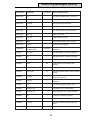
Table of contents
Contents
Introduction .................................................................................... xi
Quick Setup .................................................................................. xiii
SECTION 1: SYSTEM ARCHITECTURE ........................ 1
Overview .......................................................................................... 1
Stand-by Battery ................................................................................. 6
System Installation and Wiring ........................................................ 6
RS485 Data Communication Line (AB Line) ......................................... 7
Memory .............................................................................................. 8
RS485 Wiring Recommendations ................................................................................... 8
Zones ................................................................................................ 9
Wiring Zones ...................................................................................... 9
Wiring Multiple Zones ........................................................................ 10
Wiring Keyswitches .......................................................................... 10
Wiring Exit Terminators (Push-to-Set) ................................................ 10
Wiring the Line Fail Zone ................................................................... 11
Line Fail in the Unset State ........................................................................................... 11
Line Fail in the Set State ............................................................................................... 11
Outputs ............................................................................................ 11
Fixed Outputs ................................................................................... 12
Bell ............................................................................................................................... 12
Strobe .......................................................................................................................... 12
Horn ............................................................................................................................. 12
Voltage Outputs ................................................................................ 13
Auxiliary 12 V d.c. ....................................................................................................... 13
Hold-Off ....................................................................................................................... 13
Programmable Outputs ..................................................................... 13
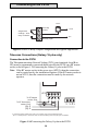
Telecoms Connections (Galaxy 16 plus only) ................................ 14
Connection to the PSTN .................................................................... 14
Connecting Additional Telecom Apparatus .................................................................. 15
The Galaxy 16 plus and BT RedCare STUs ................................................................. 15
Regulations ...................................................................................... 15
Public Switched Telephone Network (PSTN) Approval ......................... 16
REN and SEN Numbers .................................................................... 16
Private Branch Exchange (PBX) Connection ....................................... 17
iii
Table of contents (cont’d)
SECTION 2: OPTIONAL MODULES ............................. 19
Galaxy Remote Input Output (RIO) Module ................................... 19
RIO Tamper ...................................................................................... 19
Addressing the RIO ........................................................................... 19
Connecting the RIO ........................................................................... 19
RIO Zones ........................................................................................ 20
RIO Outputs ..................................................................................... 20
Configuring the RIO ........................................................................... 20
3 A Smart Power Supply Unit (Smart PSU) ................................... 21
RS232 Interface Module ................................................................. 22
RS232 Tamper .................................................................................. 23
Galaxy RS232 Settings ..................................................................... 23
Copy and Overwrite ........................................................................... 23
Interfacing with a PC ......................................................................... 23
Galaxy RS232 Module as a Serial Printer Interface ............................. 23
Printer Interface Module ................................................................ 24
Galaxy Gold .................................................................................... 25
Alarm Monitoring ........................................................................... 25
3GSTU-PLI (Galaxy 16 plus only) ................................................... 25
SECTION 3: GALAXY KEYPADS .................................. 27
General ........................................................................................... 27
Power Consumption .......................................................................... 27
Wiring .............................................................................................. 27
Addressing ....................................................................................... 28
Tamper Switch .................................................................................. 28
Backlighting ...................................................................................... 28
Keypad Mounting Procedure ......................................................... 29
Adding a Keypad to the System .................................................... 30
Configuring a Keypad on to the System ........................................ 30
Removing a Keypad from the System ........................................... 31
Keypad Self Diagnostics ................................................................ 31
Keypad Operation .......................................................................... 31
Number Keys .................................................................................... 31
iv
Table of contents (cont’d)
View Key .......................................................................................... 32
Escape Key ...................................................................................... 32
Enter Key ......................................................................................... 32
Hash Key ......................................................................................... 32
Star Key ........................................................................................... 32
Star Key Features ........................................................................... 33
Power LED ...................................................................................... 35
Viewing the Zone Resistances using the Star Key .............................. 35
Banner ............................................................................................ 36
SECTION 4: SETTING OPTIONS .................................. 37
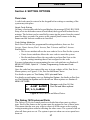
Overview ........................................................................................ 37
Illegal Code Entries ....................................................................................................... 37
Code Setting Attributes ................................................................................................ 37
The Galaxy 16/16 plus and Parts ................................................... 37
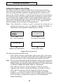
Setting the System (the A Key) ...................................................... 38
Part Setting the System (The B Key) ............................................. 39
Interrupted Setting (Full or Part) .................................................... 40
Setting with Omitted Zones ............................................................ 40
Silent Setting .................................................................................. 41
Cancelling the Setting ................................................................... 41
Unsetting the System (Code + ent Key) ......................................... 41
Part Unsetting (Code + B Key) .......................................................... 41
Engineer Unsetting ........................................................................... 42
Keyswitch Setting Options ............................................................. 42
Setting and Unsetting the System with a Keyswitch ........................... 42
Setting Features ............................................................................. 42
Exit Time .......................................................................................... 42
Omitted Zones .................................................................................. 42
Expiry Warning ................................................................................. 43
Entry Time ........................................................................................ 43
Entry Time-Out ................................................................................. 43
Straying From the Entry Route .......................................................... 43
Power Failures while the System is Set ............................................. 43
v
Table of contents (cont’d)
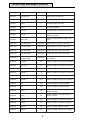
SECTION 5: MENU OPTIONS ....................................... 45
General ........................................................................................... 45
Engineer Mode ................................................................................. 45
Menu Access ................................................................................... 46
Direct Access .............................................................................................................. 46
Menu Driven Access .................................................................................................. 47
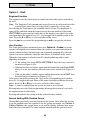
Option 1 - Omit ............................................................................... 48
Engineer Function ............................................................................. 48
User Function ................................................................................... 48
Normal Setting With Omitted Zones ................................................... 48
Option 2 Chime ............................................................................... 50
Option 3 - Walk ............................................................................... 51
Option 4 – Codes ............................................................................ 52
User Function ................................................................................... 52
Engineer Code Access ...................................................................... 52
Programming Codes and Code Attributes ........................................... 53
Assigning and Changing Codes ................................................................................... 53
Deleting Codes ............................................................................................................. 53
Programming Codes Attributes .................................................................................... 54
Codes and Keyswitches .................................................................... 55
Option 5 – Test ................................................................................ 56
Option 6 – Parameters ................................................................... 57
Selecting and Modifying Parameters .................................................. 58
01 Entry Time ............................................................................................................... 58
02 Exit Time .................................................................................................................. 58
03 Bell Time .................................................................................................................. 59
04 Re-arm Mode .......................................................................................................... 59
05 Number of Re-arms ................................................................................................. 59
06 User Options ........................................................................................................... 59
07 Reset ....................................................................................................................... 63
08 Bell Delay ................................................................................................................ 64
09 Cold Start ................................................................................................................ 64
10 Remote Reset .......................................................................................................... 65
11 Remote Version ....................................................................................................... 65
12 Banner Top .............................................................................................................. 65
13 Banner Bottom ........................................................................................................ 66
14 Part Exit Time ........................................................................................................... 66
15 Confirm Time ........................................................................................................... 66
vi
Table of contents (cont’d)
Option 7 – Zones ............................................................................. 67
Modifying Zones ................................................................................ 67
Zone Types ....................................................................................... 68
01 Final ......................................................................................................................... 68
02 Exit/Entry ................................................................................................................. 68
03 Intruder .................................................................................................................... 68
04 Keyswitch ............................................................................................................... 68
05 Fire .......................................................................................................................... 69
06 Entry ........................................................................................................................ 69
07 Push Set .................................................................................................................. 69
08 PA ........................................................................................................................... 69
09 PA Silent .................................................................................................................. 69
10 Dual ......................................................................................................................... 70
11 Security ................................................................................................................... 70
12 Spare ...................................................................................................................... 70
13 Link A ...................................................................................................................... 71
14 Link B ...................................................................................................................... 72
Zones and Soak Test ...................................................................... 72
Option 8 – Outputs .......................................................................... 73
Modifying Outputs ............................................................................. 73
Output Types .................................................................................... 74
1 Fire ............................................................................................................................ 74
2 PA .............................................................................................................................. 74
3 Intruder ...................................................................................................................... 74
4 Set ............................................................................................................................. 75
5 Bells .......................................................................................................................... 75
6 Strobe ....................................................................................................................... 75
7 Switch DC ................................................................................................................. 75
8 Security ..................................................................................................................... 76
9 Confirm ...................................................................................................................... 76
10 Horn ........................................................................................................................ 76
11 Medical .................................................................................................................... 76
12 AC Fail ..................................................................................................................... 76
13 Link A ...................................................................................................................... 76
14 Link B ...................................................................................................................... 76
15 Batt Low ................................................................................................................. 77
16 Tamper .................................................................................................................... 77
vii
Table of contents (cont’d)
Option 9 – Log ................................................................................ 78
Viewing the Event Log from a Keypad ................................................ 78
Printing the Event Log ....................................................................... 78
Event Log Details .............................................................................. 79
Option 10 – Time ............................................................................ 80
Summer Time ................................................................................... 80
Option 11 – Text .............................................................................. 81
SECTION 6: COMMUNICATIONS MENU OPTIONS ...... 83
Option 12 – Communications 1 (16 plus only) ................................ 83
Engineer Test .................................................................................... 83
BT Answer Service Dial Tone Detect .................................................. 83
01 Account No. ................................................................................. 85
02 Telephone Number 1 ..................................................................... 85
03 Telephone Number 2 ..................................................................... 85
04 Format ......................................................................................... 85
05 Receiver ....................................................................................... 86
06 Dial Type ...................................................................................... 86
07 Triggers ........................................................................................ 87
DTMF Triggers .............................................................................................................. 87
SIA Triggers ................................................................................................................. 88
08 Autotest ....................................................................................... 89
09 Interval ......................................................................................... 90
10 Access ........................................................................................ 90
11 Remote Telephone ........................................................................ 91
12 – 15 Home Numbers ..................................................................... 91
12 Home1–SIA ............................................................................................................. 91
13 Home2–Microtech ................................................................................................... 91
14 Home3–Audible ....................................................................................................... 92
15 Home4–Audible ....................................................................................................... 92
Option 13 – Communications 2 (16 plus only) ................................ 93
1 Number of Rings ............................................................................ 94
2 Line Fail ......................................................................................... 94
Adaptive Timed Dialling (Blind Dialling) ......................................................................... 95
3 Fail to Communicate ...................................................................... 95
4 STU Options .................................................................................. 96
1 Enable STU ................................................................................................................ 96
2 C/OP–Reset ............................................................................................................... 96
3 C/OP Set/Unset ......................................................................................................... 96
4 C/OP–Rem.Serv ........................................................................................................ 96
5 Monitor STU LF .......................................................................................................... 97
6 Digi if STU Fail ........................................................................................................... 97
viii
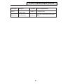
Table of contents (cont’d)
5 STU Triggers .................................................................................. 97
6 Home 1 Triggs ............................................................................... 98
7 Home 2 Triggs ............................................................................... 98
8 Conf Aftr Ent .................................................................................. 99
9 Disable Kpads ............................................................................... 99
0 Never ........................................................................................................................ 99
1 Entry Only ................................................................................................................ 99
Set or Entry .................................................................................................................. 99
10 ET Starts CT ................................................................................ 99
11 Exit RT Conf ................................................................................. 99
1 Always ..................................................................................................................... 99
2 Before Entry .............................................................................................................. 99
12 Repeat 1st ZN .............................................................................. 99
1 Leave Confirm ........................................................................................................... 99
2 Restart C/Tim ............................................................................................................. 99
13 Rprt Ent Alrm ............................................................................. 100
1 Never ...................................................................................................................... 100
2 Immediately .............................................................................................................. 100
3 At Ent T/Out ............................................................................................................. 100
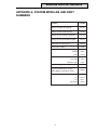
Appendix A: System Modules and part numbers ............................ I
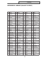
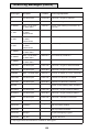
Appendix B: Library (Galaxy 16 only) ............................................. III
Appendix C: Event log messages ................................................... V
ix
x
Introduction
Introduction
The Galaxy 16 and 16 plus are versatile, technologically advanced, 8–16 zone
security control panels designed for residential and smaller commercial installations.
This guide contains the information required to install, program and operate the
Galaxy 16 and 16 plus control panels. The guide assumes that the Galaxy 16/16
plus control panel is fitted with software version V2.00 or above.
The Galaxy control panels default to standard functions and parameters, this
means that the panels are operational on power up, however, an extensive range
of functions and parameters can be modified to satisfy individual installation
requirements.
The Galaxy 16 and 16 plus control panels are simple to install and program. Nevertheless, please read the guide carefully before using the system and retain it for
future reference.
xi
xii
Quick Setup
Quick Setup
To quickly set up a Galaxy 16 or 16 plus these simple steps should be followed.
Note: these steps should not be followed for a first time set up procedure, only
those familiar with the Galaxy 16 and 16 plus control panels should use the
quick set up procedure.
1. Connect a 1kΩ (±1%) resistor across each of the zone terminals on the
Galaxy Control Panel, and the Galaxy RIO or Smart Power Supply (if fitted).
2. Ensure that the tamper reyurn loop, the terminal marked as T on the control
panel PCB is chorted to 0 V at one of the terminals marked as - on the
control panel PCB.
3. Connect a keypad to the line terminals on the control panel PCB. Connect
the terminals as follows:
Control PCB
Galaxy Ke ypad
+
+
-
-
A
A
B
B
4. Connect a 680 Ω end-of-line resistor across the A abd B terminals of the
Galaxy keypad.
5. Ensure that the keypad is fitted to the keypad mounting bracket: a keypad
tamper occurs if the tyamper spring is not retained when the system is
powered up.
6. Connect the mains wiring to the control panel - do not switch on the a.c.
mains supply.
7. Replace te control panel enclosure lid and secure the fastening screws.
8. Turn on the a.c. mains supply.
9. The following events occur:
• the Galaxy keypad buzzer and the control panel speaker output activate.
• the Galaxy keypad shows ÜÜÜÜÜÜÜÜ on the LCD display.
• the sounders stop and the keypad display goes blank.
• the green power LED on the Galaxy keypad illuminates.
• the default banner is displayed on the Galaxy keypad.
10. The system is now ready to be programmed, refer to Section 5: Menu
Options for details on the programming of the panel.
xiii
xiv
Overview
Section 1: SYSTEM ARCHITECTURE
Overview
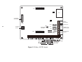
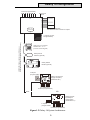
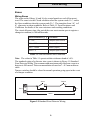
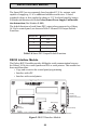
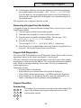
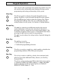
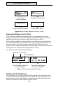
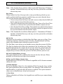
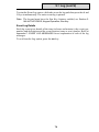
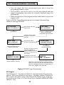
The Galaxy 16 is an eight zone, seven output security control panel. All eight
zones are programmable and four of the outputs are programmable, the Galaxy
16 also has non programmable Bell, Strobe and Horn outputs fitted, see System
Architecture; Outputs. The Galaxy 16 can be expanded to 16 (programmable)
zones and 11 outputs (eight programmable) with the addition of a Galaxy
Remote Input/Output (RIO) module or a Galaxy Smart Power Supply Unit
(Smart PSU). The Galaxy 16 also features a Line Fail zone to monitor telephone
lines for use with BT RedCare. The Galaxy 16 will operate with three keypads
fitted. The Galaxy 16 is also compatible with the Galaxy RS232 module and the
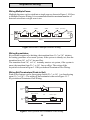
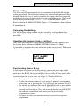
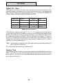
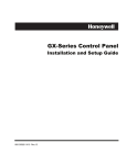
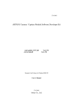
Galaxy Printer Interface module. Figure 1.1 outlines the layout of the Galaxy 16
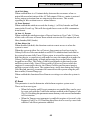
PCB. Figure 1.2 gives a summary of the Galaxy 16 system. The outputs of the
Galaxy 16 can be used to trigger a 3 GSTU (12 V).
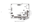
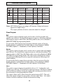
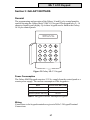
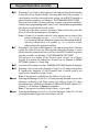
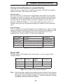
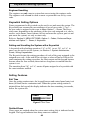
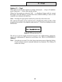
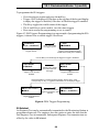
The Galaxy 16 plus has all the features of the Galaxy 16 (with the exception of
the Line Fail zone) and also features an on-board dialler (telecom module) with
Line Fail detection capabilities built in. The Galaxy 16 plus also has the ability to
work with a 3 GSTU-PLI plugged onto the appropriate sockets (SK1 and SK2).
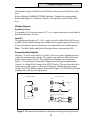
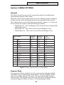
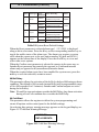
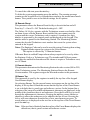
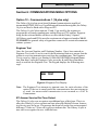
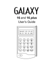
Figure 1.3 outlines the layout of the Galaxy 16 plus PCB. Figure 1.4 gives a
summary of the Galaxy 16 plus system.
Note: The Galaxy 16 and 16 plus are not compatible with the Galaxy MAX
reader (in On-Line mode).
Appendix A at the back of the manual lists Galaxy 16,16 plus and optional,
compatible module part numbers.
1
8 7 6 5 4 3 2 1
SK1 x x x x x x x x
LED
Lid Tamper
Microswitch
B
LED
+ A
- TT
AC
SW1
BATT
1A
RV2
2
Telephone
Socket
+
+
+
A
B
BELL
ENTRY/EXIT
VOLUME
1A
AUX
RJ11
1A
SK2
1
2
3
4
8 7 6 5 4 3 2 1
x x x x x x x x
5 6
7 8
LF T
680 Ω EOL
resistor
+ 1
1 2
SAB HOLD 16Ω
Line Fail
Tamper
Bell
Strobe
Figure 1.1 Galaxy 16 PCB Layout.
3
Battery
Connectors
Power Input
D
C
Auxilliary 12V
Power Outputs
L
I
N
E
AB and Power
Outputs
4
Programmable Outputs
Horn Output
Hold - Offs
Galaxy 16 PCB
IC1
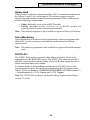
Galaxy 16 Configuration
8 zones (Programmable)
Line Fail
Zone
3GSTU 12 V (Optional)
Connected via clean contacts to outputs
Galaxy 16+
Control Panel
GALAXY 504 V4.00
08:58 TUE 22 NOV
1
2
3
A
4
5
6
B
7
8
9
ent
*
0
#
esc
Galaxy Mk V11 LCD Keypad
addressed as 0, 1 or 2
(maximum of three keypads)
Galaxy Printer
Interface (optional)
Galaxy RS232
Module (optional)
1 2 3 4 5 6 7 8
AB (RS485) Communication Line of (1km max)
Screened Twisted Pair Cable (Belden Equivalent 8723)
7 Outputs (3 Fixed,
4Programmable)
4 Outputs
(Programmable)
Galaxy Smart Power
Supply Unit (PSU)
(addressed as 1)
8 Zones (Programmable)
OR
Either:
Galaxy Remote
Input/Output
module (RIO)
(Addressed as 1)
4 Outputs
(Programmable)
8 Zones (Programmable)
Figure 1.2 Galaxy 16 System Architecture.
3
Plug-on STU
Header
8 7 6 5 4 3 2 1
SK1 x x x x x x x x
IC1
Lid Tamper
Microswitch
B
LED
+ A
- TT
AC
SW1
4
BATT
1A
RV2
Telephone
Socket
ENTRY/EXIT
VOLUME
+
+
+
A
B
BELL
1A
AUX
RJ11
1A
SK2
8 7 6 5 4 3 2 1
x x x x x x x x
680 Ω EOL
resistor
2
3
4
5 6
7 8
LF T
+ 1
1 2
SAB HOLD 16Ω
Line Fail
Tamper
Bell
Strobe
Figure 1.3 Galaxy 16 plus PCB Layout
3
Power Input
D
C
Auxilliary 12V
Power Outputs
L
I
N
E
AB and Power
Outputs
A B C D
1
Battery
Connectors
4
Programmable Outputs
Horn Output
Hold - Offs
Galaxy 16 Plus PCB
LED
Galaxy16 Plus Configuration
8 zones (Programmable)
On-board Dialler
3GSTU Plug-on (Optional)
Galaxy 16+
Control Panel
GALAXY 504 V4.00
08:58 TUE 22 NOV
1
2
3
A
B
4
5
7
8
9
ent
*
0
#
esc
6
Galaxy Mk V11 LCD Keypad
addressed as 0, 1 or 2
(maximum of three keypads)
Galaxy Printer
Interface (optional)
Galaxy RS232
Module (optional)
1 2 3 4 5 6 7 8
AB (RS485) Communication Line of (1km max)
Screened Twisted Pair Cable (Belden Equivalent 8723)
7 Outputs (3 Fixed,
4Programmable)
4 Outputs
(Programmable)
Galaxy Smart Power
Supply Unit (PSU)
(addressed as 1)
8 Zones (Programmable)
OR
Either:
Galaxy Remote
Input/Output
module (RIO)
(Addressed as 1)
4 Outputs
(Programmable)
8 Zones (Programmable)
Figure 1.4 Galaxy 16 plus System Architecture.
5
Installation Recommendations
System Installation and Wiring
The installation and wiring must be performed by a competent engineer. For
permanently connected equipment a readily accessible disconnect device must
be incorporated into the fixed wiring with contact separation of at least 3 mm on
each pole. The Galaxy control panel must be connected to the a.c. mains supply
(230 V (+10%, – 8%) a.c. 50 Hz) via a fused connection outlet.
The fuse in the mains outlet must not exceed 3 A.
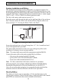
Route the mains cable through the hole on the right hand side of the enclosure
base. Securely anchor the cable to the enclosure base using the cable tie as
shown in Figure 1.5 Securing the Mains Cable to the Panel.
From fused
connection
unit
Cable tie
To Transformer
Connector
Block
To Connector
Block
Figure 1.5 Securing the Mains Cable to the Panel.
Secure the enclosure base to the wall using three 1.5" No. 8 round-head steel
screws through the holes provided.
The mains cable used must be a three core type (with green/yellow earth
insulation) of adequate current carrying capacity.
Note: The mains cable must satisfy the requirements stated in BS6500.
Connect the mains cable to the mains terminal block as follows:
• blue wire to the terminal marked N (Neutral)
• green/yellow wire to the terminal marked (Earth)
• brown wire to the terminal marked L (Live)
Note: No other connections to the mains connector are permitted.
All wiring must be in accordance with the latest edition of the IEE Wiring
Regulations (Regulations for Electrical Installations), see also BS7671.
Once all zone and module wiring has been completed replace the lid of the
enclosure and screw the lid to the base with the screws provided.
Stand-by Battery
The Galaxy 16/16 plus can accommodate a 15 Ahr stand-by battery in the
control panel enclosure. Ensure that the battery connector leads on the control
panel PCB are connected to the correct terminals on the battery.
6
RS485 Recommendations
RS485 Data Communication Line (AB Line)
Communication between the Galaxy control panels and the attached modules
takes place on the AB (RS485) communication line. The control panel constantly monitors the modules attached to it. A break in the communication from
any of the modules generates a module tamper alarm.
It is strongly recommended that the system is wired in daisy chain configuration, the recommended maximum length of the AB line is 1 km. For more
information see RS485 Wiring Recommendations below.
A
1
2
3
A
2
3
4
5
6
B
4
5
6
7
8
9
ent
7
8
9
ent
0
#
esc
*
0
#
esc
*
R38 EOL Resistor
(Factory fitted to
control panel PCB)
GALAXY 16+ V2.7
08:58 TUE 22 NOV
GALAXY 16+ V2.7
08:58 TUE 22 NOV
Galaxy 16/16 plus Control Panel
1
B
680 Ω EOL
Resistor
A
B
Figure 1.6 Daisy-Chain Configuration.
Two AB lines can be run from the control panel. This requires a minor hardware
modification to the control panel PCB, see Figure 1.7 Twin AB Line Daisy-Chain
Configuration.
• Cut resistor R38 on the control panel PCB.
• Run two lines from the A and B terminals.
• Terminate both Ends of Line with a 680 Ω resistor.
GALAXY 16+ V2.7
08:58 TUE 22 NOV
1
2
3
GALAXY 16+ V2.7
08:58 TUE 22 NOV
GALAXY 16+ V2.7
08:58 TUE 22 NOV
Galaxy 16/16 plus Control Panel
A
1
2
3
A
1
2
3
A
4
5
6
B
4
5
6
B
4
5
6
B
7
8
9
ent
7
8
9
ent
7
8
9
ent
*
0
#
esc
*
0
#
esc
*
0
#
esc
680 Ω EOL
Resistor
R38 EOL Resistor
To be removed
X
680 Ω EOL
Resistor
A
B
Figure 1.7 Twin AB Line Daisy-Chain Configuration.
Note: If a twin AB line configuration is to be used the maximum cable run is 1
km over both runs not 1 km per run.
7
RS485 Recommendations
RS485 Wiring Recommendations
To ensure that the system communicates at the maximum level of efficiency the
following recommendations must be adhered to:
1. It is strongly recommended that the system is wired in a daisy-chain
configuration. That is, the A terminal from the previous module is
connected to the A terminal of the current module and then on to the A
terminal of the next module. The B line should be connected in the same
manner. Spur and star configurations should not be used as they reduce
immunity to electrical interference.
2. The cable used to wire the AB line should be screened, twisted pair
(Belden equivalent 8723) Part No. W002.
3. Screened, twisted pair cable, where used, is connected to ground (0 V)
only at the P-clip in the control panel enclosure, see Figure 1.8 P-Clip
Connection.
4. The AB line must have a 680 Ω End-of-Line (EOL) resistor fitted across
the A and B terminals of the last module on the line. If two runs are
connected, both ends must be terminated with 680 Ω (EOL) resistors
and R38 on the control panel PCB must be cut, see Figure 1.7 Twin AB
Line Daisy Chain Configuration.
5. The power supply in the Galaxy control panel and remote power
supplies must not be connected in parallel. The 0 V of all remote power
supplies should be connected in common to the 0 V of the Galaxy
control panel.
AB connectors
B
A
data line
data line
RS 485 cable
Cable screen
P-clip
Nut
P-clip
Earthing pillar
(threaded)
Figure 1.8 P-Clip connection.
Memory
The Galaxy 16 and 16 plus control panels are fitted with a Non Volatile Memory
(NVM) chip. This allows the panels to retain programming details when both
the mains power and stand-by battery have been disconnected. The NVM can
be transferred from a Galaxy 16 or 16 plus to another without loss of programming.
Note: On swapping NVMs between a Galaxy 16 and 16 plus it is strongly
recommended that the programming is restored to the factory defaults
using the Cold Start parameter, refer to Section 5: MENU OPTIONS;
Option 6 – Parameters; 9 Cold Start.
8
Zone Wiring
Zones
Wiring Zones
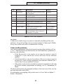
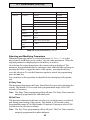
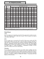
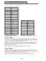
The zones on the Galaxy 16 and 16 plus control panels are end-of-line monitored. The zone is in the Closed condition when the system reads 1 kΩ and in
the Open condition when the system reads 2 kΩ. The transition from 1 kΩ to 2
kΩ generates an alarm condition. Refer to Table 1.1 Zone Resistance and
Conditions for details of the zone resistance and resulting conditions.
The circuit debounce time (the period the zone must remain open to register a
change in condition) is 300 milliseconds.
Zone Resistance ( Ω )
Condition
0 - 720
Tamper Short Circuit
721 - 1300
Normal (Closed)
1301 - 12500
Alarm (Open)
12501 - α
Tamper Open Circuit
Table 1.1 Zone Resistance and Conditions.
Note: The values in Table 1.1 operate within a tolerance band of ±4%.
The standard wiring of a detector into a zone is shown in Figure 1.9 Standard
Zone/Detector Wiring. The recommended maximum cable run from a zone to a
detector is 500 metres. This recommendation is based on 7 × 0.2 mm multicore
cable.
Tamper switches should be closed in normal operation going open in the event
of a tamper condition.
Tamper
Alarm
N/C
Zone
N/C
1k
1%
1k 1%
500 m
Figure 1.9 Standard Zone/Detector Wiring.
9
Keyswitch Wiring
Wiring Multiple Zones
Multiple detectors can be wired into a single zone as shown in Figure 1.10 Zone
to Multiple Detector Wiring. It is recommended that the maximum number of
detectors wired into a single zone is ten.
Alarm
N/C
Zone
Alarm
N/C
Alarm
N/C
Alarm
N/C
(10 max)
N/C TAMP
N/C
1k
1k
1k
1k
1%
1%
1%
1%
1% 1k
500 m
Figure 1.10 Zone to Multiple Detector Wiring.
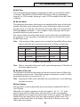
Wiring Keyswitches
Keyswitches require to be latching, the transition from 1 kΩ to 2 kΩ initiates
the setting procedure of an unset system; if the system is already set, then the
transition from 1 kΩ to 2 kΩ has no effect.
The transition from 2 kΩ to 1 kΩ instantly unsets a set system, if the system is
unset, the transition from 2 kΩ to 1 kΩ has no effect. The wiring of the
keyswitch is shown in Figure 1.11 Keyswitch and Terminator Zone Wiring.
1k to unset, 2k to set
1k
Open - Closed
Push-set
zone
OR
1k
Keyswitch
zone
1%
1k
Wiring Exit Terminators (Push-to-Set)
Push-to-Set buttons can be open going closed (2 kΩ to 1 kΩ) or closed going
open (1 kΩ to 2 kΩ). The wiring of the terminator is shown in Figure 1.11
Keyswitch and Terminator Zone Wiring.
1%
1%
Closed - Open
1k
1%
1%
1k
500m
Figure 1.11 Keyswitch and Terminator Zone Wiring.
10
Line Fail Zone Wiring
Note: The activation of an exit terminator during the first setting of the system
may not set the system, it may be taken as the initialisation routine. If
the system continues setting, push the button again, the system will set
on the second push. This initialisation only occurs on the first setting
after the zone has been programmed as Push Set. All subsequent
setting routines set on the first push of the terminator.
Wiring the Line Fail Zone
The Galaxy 16 provides a dedicated Line Fail zone. This allows a digital communicator, which can be attached to the Galaxy 16 outputs, to be monitored for
communications failure. The line fail output from the digital communicator must
be negative removed in activation and is wired directly into the Galaxy 16 Line
Fail zone. It is controlled by the STU programming. See Section 5 MENU
OPTIONS: Option 13 – Communications 2; 4 STU options for programming
details.
Note: No resistors should be connected to the Line Fail zone.
Line Fail in the Unset State
On the detection of a line fail in the unset state, a local alarm sounds and the
LCD keypad displays the message ALARM IN PROGRESS. Entering a valid code
cancels the alarm, the keypad display reads LINE FAIL. Subsequent Line Fail
conditions will have visual indication only, the keypad will not give audible
indication of a Line Fail until the system has been reset by an engineer.
Line Fail in the Set State
A line fail in the set state overrides the Bell Delay, refer to Section 5: MENU
OPTIONS; Option 6 – Parameters; 8 Bell Delay, there is no alarm indication. If
an alarm occurs during the line fail, then outputs programmed as Bells, Strobe
and Horn activate immediately. On unsetting the system the keypad indicates
that a line failure has occurred by displaying the LINE FAIL message.
Outputs
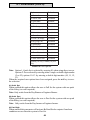
The Galaxy 16 and 16 plus control panels have seven outputs, three nonprogrammable and four programmable. The three non-programmable outputs
are Bells, Strobe and Horn. The four programmable outputs default to Fire, PA,
Intruder and Set. The Galaxy control panel outputs are detailed in Table 1.2
Galaxy 16/16 plus Outputs.
11
Control Panel Outputs
Output
Function Programmable
Type
Current
Voltage
Normal State
Bell
No
Transistorised
400 mA
12 V
Positive
Strobe
No
Transistorised
400 mA
12 V
Positive
Horn
No
Transistorised
400 mA
12 V
Positive
1
Fire
Yes
Transistorised
400 mA
12 V
Positive
2
PA
Yes
Transistorised
400 mA
12 V
Positive
3
Intruder
Yes
SPCO Relay
1A
30 V
De-Energised
4
S et
Yes
Transistorised
400 mA
12 V
Positive
Table 1.2 Galaxy 16/16 plus Outputs.
Notes: SPCO Relay figures are ratings, all Transistor Voltage and current
figures are output values.
The output polarities (Positive removed) cannot be changed.
Fixed Outputs
Bell
This positive removed output can be used to drive a bell or sounder and
supplies up to 400 mA. The fixed Bell output activates in a full alarm condition.
This output is subject to Bell Time, Bell Delay and Re-arm, refer to Section 5:
MENU OPTIONS for programming details.
To prevent the Bell outputs from activating when the system is Part Set,
disable (default is enabled) the Part Bells option, refer to Section 5: MENU
OPTIONS; Option 6 – Parameters; 6 User Options; Part Bells.
Strobe
This positive removed output can be used to drive a strobe light and supplies
up to 400 mA. The fixed Strobe output activates in a full alarm condition. This
output is subject to Bell Time, Bell Delay and re-arm, refer to Section 5: MENU
OPTIONS for programming details. The output can be disabled from the Re–
Arm parameter allowing the strobe to operate continuously following a full
alarm condition.
To prevent the Strobe outputs from activating when the system is Part Set,
disable (default is enabled) the Part Bells option, refer to Section 5: MENU
OPTIONS; Option 6 – Parameters; 06 User Options; 03 Part Bells.
Horn
This positive removed output is intended to drive a 16 Ω loudspeaker and
supplies up to 400 mA. The fixed Horn output activates in a full alarm condition,
in a local alarm condition, during the setting and unsetting procedures and on
the activation of a zone programmed to Chime.
The output volume can be altered using the potentiometer (R47). This only
affects the output volume for entry tones, exit tones and Chime – the output
volume for alarm conditions is fixed at the maximum setting.
12
Output Applications
This output is subject to Bell Time, Bell Delay and re-arm in a full alarm condition.
Refer to Section 5: MENU OPTIONS; Option 8 – Outputs for programming
details and Option 2 – Chime for details on the operation of the Chime function.
Voltage Outputs
Auxiliary 12 V d.c.
Two negative (0 V) and two positive 12 V d.c. supply terminals are provided for
detectors and other devices.
Hold-Off
This positive and negative 12 V d.c. output is used to hold off the Self Activating Bell (SAB) and to recharge the sounder battery when required. The output
is current limited to prevent shorting or over demand by the sounder battery.
Note: The Bell, Strobe and Hold-off outputs share a common fuse (F2).
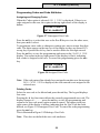
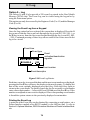
Programmable Outputs
Outputs 1, 2 and 4 on the Galaxy 16 and 16 plus are negative applied (positive
removed), transistorised outputs. The outputs can sink up to 400 mA and are
used to drive output devices. The transistorised outputs are illustrated in
Figure 1.12 Transistorised Output Configuration and Typical Applications.
Output 3 is a Single Pole Change Over (SPCO) Relay. This can be used to drive
output devices that require a clean set of contacts, isolated from the output
voltage. The SPCO Relay output is illustrated in Figure1.13 SPCO Relay Output
Configuration and Typical Application.
Transistorised Output
Typical Applications
A) LED
Output
LED
+12 V
+12 V
1kΩ (typical)
3k3Ω
B) Bell
Output
Bell
+ 12 V
Output
0V
C) Output used to trigger zone
Output
Cut 3k3Ω to give
open collector
1kΩ
1%
zone
Output must be
open collector
1kΩ
1%
Figure 1.12 Transistorised Output Configuration and Typical Applications.
13
Connecting to the PSTN
Horn
Single Pole
Change - 0ver
relay contacts
Normally
closed
+12 V
0V
Normally open
Figure 1.13 SPCO Relay Output Configuration and Typical Application.
Telecoms Connections (Galaxy 16 plus only)
Connection to the PSTN
The Telecommunications Network Voltage (TNV) port (terminals A and B on
JP3) must be permanently connected (hard-wired) to the PSTN via a BT master
socket, refer to Figure 1.14 Connecting the Galaxy 16 plus to the PSTN.
Note: If the BT master socket is the newer type (NTE5), then the connection
can be carried out by the installation engineer. If the BT master socket is
not an NTE5, then the connection must be made by the network
operator.
JP3
To BT Master
socket, Pins:
To BT Secondary
2
socket, Pins:
5
(5)† 2
(2)† 5
A B C D
1
2
† Some Secondary Sockets may have mirror images of the correct PIN assignments
(Pin 1 is actually Pin 6). If this is the case, connect the Galaxy plus to the pins given in brackets.
Figure 1.14 Connecting the Galaxy 16 plus to the PSTN.
14
3
Connecting to the PSTN
Using cable suitable for connection to 2.8 mm diameter screw terminals, strip
back approximately 20 mm of the outer sheath and then remove approximately 4
mm of the insulation from the wires to be connected to the Galaxy 16 plus.
Connect the A wire to contact 2 on the BT master socket and the B wire to
contact 5. Connect the A and B wires to the A and B terminals of JP3 on the
Galaxy 16 plus, see Table 1.3 PSTN Connections to the Galaxy 16 plus.
Note: The cover of the control box must be replaced whenever any
connection to the BT master socket is completed to prevent exposure to
potentially lethal voltages from the PSTN.
Interconnection circuits should be such that the equipment continues to
comply with the requirements of 4.2 of EN41003 for TNV (Telephone Network
Voltage) circuits and 2.3 of EN60950 of SELV (Safety Extra Low Voltage) circuits,
after making connections between circuits.
Connecting Additional Telecom Apparatus
A BT secondary socket, allowing additional telecom apparatus to be connected
in series with the Galaxy 16 plus can be connected to the TNV port C and D
(JP3) on the Galaxy 16 plus see Figure 1.14 Connecting the Galaxy 16 plus to the
PSTN.
Connect the contacts on the BT secondary socket to the JP3 as follows:
BT Master Socket BT Secondary Socket (if used)
Galaxy 16 plus (JP3)
2
-
A
5
-
B
-
2 (5)…
C
-
5 (2)…
D
… Some BT Secondary Sockets may have mirror images of the correct PIN assignments (Pin 1
is actually Pin 6). In this case connect the Galaxy 16+ terminal to the Pin numbers given in
brackets
Table 1.3 PSTN Connections to the Galaxy 16 plus.
The Galaxy 16 plus and BT RedCare STUs
As both the Galaxy 16 plus and STUs require to be the first modules on the line
it is strongly recommended that they are connected to different telephone lines.
Regulations
The Galaxy 16 plus is approved for connection to direct lines of the PSTN and
PBX exchanges (with or without secondary proceed indication). Tone and
Pulse dialling are supported, see note in Section 6: COMMUNICATIONS MENU
OPTIONS; 6 Format.
It should be noted that the Galaxy 16 plus is not suitable as an extension to a
payphone.
15
PSTN Approval
The Galaxy 16 plus has been approved for the use of the following facilities:
• Auto-dialling.
• Auto-answering.
• Auto-clearing.
• Modem communications.
• Series connection.
• Operation with Call Process Monitor (CPM) tone recognition.
• Multiple repeat attempts.
Any other usage invalidates the approval of the Galaxy 16 plus if, as a result, it
then ceases to comply with standards against which approval was granted.
Approval of the Galaxy 16 plus is also invalidated if it is used with internal
software or subjected to any hardware modification not authorised by BABT.
Public Switched Telephone Network (PSTN) Approval
The equipment has been approved to {Council Decision 98/482/EC} for Pan European single terminal connection to the Public Switched Telephone Network
(PSTN). However due to differences between the individual PSTNs provided in
different countries the approval does not, of itself, give an unconditional
assurance of successful operation on every PSTN network termination point.
In the event of problems contact the equipment supplier in the first instance.
The Galaxy is designed to interwork with the following networks:
Austria
France
Italy
Norway
Switzerland
Belgium
Greece
Liechtenstein
Portugal United Kingdom
Denmark
Iceland
Luxembourg
Spain
* Germany
Finland
Ireland
The Netherlands
Sweden
Note: Contact the equipment supplier before using the Galaxy 16 plus on any
network.
REN and SEN Numbers
It is possible to simultaneously connect a number of items to one line of the
PSTN. The limit is determined by summing the Ringer Equivalence Number
(REN) shown on each item of apparatus, ensuring that the sum of RENs is not
more than four.
The REN of the Galaxy 16 plus is one (1).
Assume that all British Telecom equipment has a REN of one unless otherwise
marked.
* May have interworking difficulties
16
PBX Connection
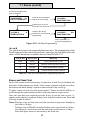
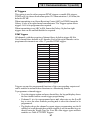
More than one item of series apparatus may be connected to the Galaxy 16 plus
TNV ports marked C and D. This is limited by summing the Series Equivalence
Number (SEN) shown on each item of series connected apparatus, ensuring
that the sum of the SENs is not more than one (1). The total series resistance,
including cabling, must not exceed 50 Ohms.
1. The SEN of the Galaxy 16 plus is 0.3.
2. Nominal series resistance is 90 milliohms.
3. Nominal insertion loss is 0.1 dB.
Note: Difficulties may be experienced when making calls from other apparatus
if the total SEN value approaches one or the total series resistance 50 Ω.
If such difficulties are experienced, please consult the Galaxy 16 plus installer or
supplier, not BT.
It is recommended that the PSTN should have the following facilities:
1. Outgoing calls only (when used as dialler only).
2. Direct exchange.
3. Pulse or tone dialling.
Private Branch Exchange (PBX) Connection
The Galaxy 16 plus is only approved for use with BABT approved PBXs.
The correct operation of the Galaxy 16 plus can not be guaranteed under all
possible conditions of connection to compatible PBXs.
When connected to a PBX, the Galaxy 16 plus can be programmed to detect an
additional dial tone or to pause for two seconds between the dialling of the
digits. For details on programming see Section 6: COMMUNICATIONS MENU
OPTIONS; 2 Telephone Number 1.
17
18
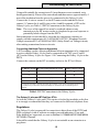
RIO’s
Section 2: OPTIONAL MODULES
Galaxy Remote Input Output (RIO) Module
S
INF
B A – + – +
LINE
LK5 INF
R7
4
R5
R3
2 3
O/P
R1
1
TMP
A Galaxy RIO module can be connected to the Galaxy 16 and 16 plus to expand
the system by eight zones and four outputs.
IC1
LED1
LK4 SLV
LK1 TAMP
SW1
LK3 MAX
LK2 E/E
SW2
1
2 3
4 5
6 7
8
Figure 2.1 Galaxy RIO Module PCB Layout.
RIO Tamper
Switch SW2 on the RIO module acts as a tamper if Link 1 is missing (absent by
default). Removal of the lid from the RIO enclosure activates the RIO tamper
alarm if the system is not in Engineer Mode. The tamper switch can be bypassed by fitting a 0 W link to LK1.
Addressing the RIO
The Galaxy RIO must be addressed as 1. It must be addressed before it is
connected to the power supply, the address is selected using the 16-way rotary
switch (SW1), refer to Figure 2.1 Galaxy RIO Module PCB Layout.
Connecting the RIO
The RIO can only be connected to the system while Engineer Mode is
accessed. It is strongly recommended that the AB line of the Galaxy RIO is
wired in parallel (daisy-chain configuration) with the AB line of any keypads
connected to the system. The RIO requires 12 V d.c. (range 10.5 V to 16.0 V)
and 50 mA. This can be supplied from the control panel power supply or from a
remote power supply if the distance causes a large voltage drop on the cable.
Note: A 3 A Smart PSU (part number P015) can be fitted in place of a RIO and
remote power supply.
The connections to the RIO terminals are given in Table 2.1 Galaxy RIO
Connections.
19
Configuring the RIO
RIO Terminal Connected to...
+
+ 12 V (at a control panel, keypad or remote power supply).
–
0 V or ground (at a control panel, keypad or remote power supply).
A
To the A terminal of the previous module on the line (or the control
panel if the RIO is the first module on the line).
B
To the B terminal of the previous module on the line (or the control
panel if the RIO is the first module on the line).
Table 2.1 Galaxy RIO Connections.
Note: The last module on the line must have a 680 Ω resistor connected across
the A and B terminals.
Configuring the RIO
The RIO is configured into the system on exiting from Engineer Mode. On
exiting Engineer Mode the message 1 MOD. ADDED — esc=CONTINUE is
displayed confirming that the RIO has been added. If this message is not
displayed then the RIO is not communicating with the control panel.
The flash rate of the red LED (LED1) on the RIO indicates the status of the
communication with the control panel — refer to Table 2.2 RIO LED Flash
Rates.
Flash Rate (seconds)
0.1 on / 0.9 off
Off
Meaning
Normal Communications
No d.c. supply
1.5 on / 1.5 off
RIO not configured into system
0.2 on / 0.2 off
RIO has lost communications with system
0.9 on / 0.1 off
RIO has poor communications with system
Table 2.2 RIO LED Flash Rates.
RIO Zones
The Galaxy RIO has eight programmable zones all of which default to Intruder.
The wiring of the RIO zones is identical to that of the zones on the Galaxy 16
and 16 plus control panels, see Section 1: SYSTEM ARCHITECTURE; Zones.
RIO Outputs
The RIO has four transistorised outputs, each output is positive removed.
When an output is activated, the load is switched to the negative supply
voltage (ground or 0 V) of the RIO. The current available from each output is
400 mA.
The default functions of each RIO output, when connected to a Galaxy 16 or 16
plus, are shown in Table 2.3 RIO Output Default Functions.
20
Smart PSU
Output No.
Default Function
1
Fire
2
PA
3
Intruder
4
S et
Table 2.3 RIO Output Default Functions.
3 A Smart Power Supply Unit (Smart PSU)
One 3 A Smart Power Supply Unit (Smart PSU) can be connected to the Galaxy
16 and 16 plus control panels. The Smart PSU integrates a three ampere power
supply with an eight zone, four output Galaxy RIO. This may be used in place
of a standard RIO to overcome power problems that arise when the additional
RIO is fitted distant to the control panel.
Notes: Only one Smart PSU or one RIO can be connected to the Galaxy 16 and 16
plus control panels.
A Smart PSU fitted to a Galaxy 16/16+ has full on-board RIO facilities but
it does not have the “Smart” power diagnostic facilities available with
other Galaxy control panels.
The addressing, zone and output wiring is identical to that of the Galaxy RIO,
see Optional Modules; Galaxy Remote Input Output (RIO) Module.
The Galaxy Smart PSU must be addressed as 1. It must be addressed before it
is powered up, the address is selected using the 16-way rotary switch (SW1),
refer to Figure 2.2 Galaxy 3 A Smart PSU PCB Layout.
Smart PCB Earth (Fit nylon washer if remote PSU)
S1
+–AB
Heat Sink
JP1
A
F4 (1.5 A)
B T – + – + 4 3 2 1
F3 (1.5 A)
R23
F2 (2.5 A)
LED1
LK3
LK2
R33
R37
SW1
R43
–+
JP3
JP2
1
2 3
4 5
6 7
8
+
–
Connect to Stand-by Battery
(observing polarity)
Figure 2.2 Galaxy 3 A Smart PSU PCB Layout.
21
RS232 Interface Module
The Smart PSU has two separately fused regulated 12 V d.c. outputs, each
capable of supplying 1.5 A to additional modules and devices. A fused
regulated voltage is also supplied to charge a 12 V lead-acid stand-by battery.
For further information refer to the Galaxy Smart Power Supply Unit Installation Instructions (Part Number: L101).
The default functions of each Smart PSU output when connected to a Galaxy
16/16 plus control panel, are shown in Table 2.4 Smart PSU Output Default
Functions.
Output No.
Default Function
1
Fire
2
PA
3
Intruder
4
S et
Table 2.4 Smart PSU Output Default Functions.
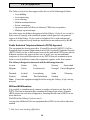
RS232 Interface Module
The Galaxy RS232 module provides full duplex serial communication between
the Galaxy 16/16 plus control panels and PCs or serial printers. This module has
three main functions:
• Copy and overwrite the control panel programming.
• Interface with a PC.
• Interface with a serial printer.
BA –+
B
A
LINE
+
–
12 V
S
LD1
S1
JP1
IC1
IC2
IC3
25 Way
Sub-D type
RS232 Connector
SW3 (Copy)
PROM1
SW 2
(Tamper)
LD3
(Copy)
IC3
Link 1 (Cut to enable tamper)
LD4 (Overwrite)
SW1 (MEM BK)
SW4 (Overwrite)
Figure 2.3 RS232 Interface Module.
22
RS232 Interface Module
RS232 Tamper
Switch SW2 on the RS232 module acts as a tamper if Link 1 is cut. Removal of
the lid from the RS232 module enclosure when the system is connected to the
Galaxy 16/16 plus activates the RS232 tamper alarm if the system is not in
Engineer Mode.
Galaxy RS232 Settings
The RS232 module is configured using the DIP switches on the PCB; the
settings are summarised in Table 2.5 RS232 Module DIP Switch Settings, for
more information see the Galaxy RS232 Operating Instructions (Part Number:
L114).
Setting
DIP Sw itch
Function
ON
OFF
1
Printer/PC interface
Printer
RS232 (PC Interface)
2
Stop Bits (2 or 1)
2
1
3
Data Bits (7 or 8)
7
8
4
Even/Odd Parity
Odd
Even
5
Parity On/Off
No-Parity
6
7
8
Baud Rate
Parity
Refer to Table 2.6
RS232 Baud Rate
Settings.
Table 2.5 RS232 Module DIP Switch Settings.
Copy and Overwrite
The control panel programming can be copied to the RS232 module and stored
for up to 28 days (indefinitely if the module is constantly powered). The
programming can then be downloaded (overwritten) to one of the following: the
same control panel, another Galaxy 16 or 16 plus, or to a PC with Galaxy Gold
software installed; Galaxy Gold can then be used to modify the site programming.
Interfacing with a PC
The Galaxy 16/16 plus control panel can be directly linked to a PC via the RS232
module allowing local servicing using Galaxy Gold.
Galaxy RS232 Module as a Serial Printer Interface
The module can also operate as an interface to a serial printer, refer to Table 2.5
RS232 Module DIP Switch Settings and to Table 2.6 RS232 Baud Rate Settings.
The RS232 must be set up with the printer setting outlined in Table 2.7 Printer
Settings. For printing instructions, refer to Table 3.3 Star Key (Ö) Combinations.
For further information refer to the Galaxy RS232 Operating Instructions (Part
Number: L114).
23
Printer Interface Module
B au d
Rate
DIP Sw itch Setting
6
7
8
300
Off
Off
Off
600
Off
Off
On
1200
Off
On
Off
2400
Off
On
On
4800
On
Off
Off
9600
On
Off
On
19200
On
On
Off
38400
On
On
On
Table 2.6 RS232 Baud Rate Settings.
Printer Interface Module
The Printer Interface module allows the Galaxy to be connected to a serial
printer and the contents of the event log and the programming details of the
system to be printed. The module is available with either a:
• 25 way sub D type RS232 serial connector (part number A161), or,
• 6 pin DIN plug (part number A134).
The printer interface module can be connected to the Galaxy system at S1 on
the control panel.
The printer must have a serial interface port. The printer protocol must be set
up as outlined in Table 2.7 Printer Settings.
Protocol
Setting
Start Bit
1
Stop Bit
1
Word Length
8 Data Bits
Parity
None
Baud Rate
1200
Table 2.7 Printer Settings.
24
Optional Software Packages
Galaxy Gold
Galaxy Gold is a software program that allows a PC to communicate and control
the Galaxy 16 and 16 plus control panels. The software program can also
upload, store and download control panel programming. Galaxy Gold operates
with the following configurations:
• Galaxy 16: locally serviced via an RS232 module.
• Galaxy 16 plus: locally serviced via an RS232 module or
remotely serviced via the on-board communicator.
Note: This software program is only available to registered Galaxy Gold users.
Alarm Monitoring
Alarm Monitoring is an advanced, high performance software programme that
allows a PC to receive and store event and alarm information from Galaxy
control panels.
Note: This software programme is only available to registered Alarm Monitoring
users.
3GSTU-PLI
The 3GSTU-PLI is a plug-on module which allows the Galaxy 16 plus to be
connected to the BT RedCARE service. The 3GSTU-PLI connects to the SK1
and SK2 connector blocks on the Galaxy 16 plus PCB which supply the power,
output and alarm input to the module.
For further details on the installation and operation of 3GSTU units see the
accompanying literature. For details on programming the STU options of the
Galaxy 16 plus see Section 6: COMMUNICATIONS MENU OPTIONS; Option 13
– Communications 2; 4 STU Outputs and 5 STU Triggers.
Note: The 3GSTU-PLI can also be used on the Galaxy 16 panel with software
version 2.7 or later.
25
26
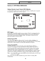
Mk 7 LCD Keypad
Section 3: GALAXY KEYPADS
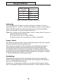
General
The programming and operation of the Galaxy 16 and 16 plus control panels is
carried out using the Galaxy Mark 7 (Mk V11) keypad. This keypad has a 2 × 16
character liquid crystal display. Up to three keypads can be fitted to the Galaxy
16/16 plus control panels.
GALAXY 16+ V2.7
08:58 TUE 22 NOV
1
2
3
A
4
5
6
B
7
8
9
ent
*
0
#
esc
Figure 3.1 Galaxy Mk V11 keypad.
Power Consumption
The Galaxy Mk III keypads require a 12 V d.c. supply from the control panel or a
remote power supply. The current consumption of the keypads is:
Mode
Current Draw Mk7 (LCD)
Backlight OFF
60 mA
Backlight ON
70 mA
Maximum (Buzzer and LED)
120 mA
Table 3.1 Keypad Current Consumption Figures.
Wiring
Connections to the keypad terminals are given in Table 3.2 Keypad Terminal
Connections.
27
Keypad Address
Galaxy Keypad
Connected to...
Terminal
B
B line
A
A line
+
12 V d.c. input
–
0V
Table 3.2 Keypad Terminal Connections.
Addressing
The valid addresses for Galaxy keypads connected to a Galaxy 16/16 plus
control panel are 0, 1, and 2. A 16-way rotary address switch is used to address
Galaxy Mk III keypads. The address switch assigns a hexadecimal address
value to the keypad. The factory default address is 0.
Notes: Any change to the keypad address must be made when the power is
disconnected from the keypad.
Each keypad must have a unique address.
Keypads can have the same address as a RIO or Smart PSU.
Tamper Switch
The Galaxy keypads provide a tamper switch that operates when the keypad is
detached from the keypad mounting bracket.
The keypads are designed to allow the option of an additional wall tamper
which will cause a tamper alarm should the entire keypad (including the
mounting bracket) be prised from its mounting. The tamper spring retainer
(located on the Galaxy keypad mounting bracket) can be knocked-out to allow
the tamper spring contact with the wall, this enables the wall tamper, see Figure
3.2 Keypad Installation and Mounting Details.
Backlighting
When initially connected to the control panel, the keypad is permanently
backlit. The backlighting can be switched off and on using the shift function
keys, refer to Star Key (Ö) Features.
During an a.c. mains failure condition, to save the available stand-by battery
power, the keypad backlight is turned of until the a.c. mains supply is restored.
28
Keypad Installation
keyhole slot
aperture
aperture
cable
channel
cable
stowage
area
sacrificial
wall
tamper
elongated
hole
knockout
hole
4-way
connector
Figure 3.2 Keypad Installation and Mounting Details.
Keypad Mounting Procedure
1. Remove the keypad from its packaging.
2. To attach the keypad to the wall, the back plate must first be removed
from the front plate. To do this, insert a suitable tool into both
openings at the bottom of the keypad and turn the tool gently.
CAUTION: When the keypad is separated make sure that the antistatic precautions are taken with the keypad pcb to avoid damage from
esd (electro static discharge).
3. Use the backplate as a template, then mark the locations for the three
attachment screws in the required position.
4. If it is a new installation, use the keyhole slot at the top of the backplate
and the two elongated holes at the bottom. If replacing an existing Mk3
keypad with a Mk7 keypad, use the keyhole slot at the top of the
backplate and the two knockout holes at the bottom. This means that
you can use the existing holes in the wall, whist keeping the
backplate in the same position.
5. If you are using a wall-run cable for the keypad (A, B, +12V, 0V) position
the cable behind the back plate in the cable channels provided. The
cable can be run in from either the top or the bottom of the back plate.
Use a sharp tool to remove the plastic from the top or the bottom of the
cable guides on the back plate skirting.
29
Adding a Keypad
CAUTION:
Use of any screws other than No. 6 Pan-head can
damage thekeypad mouldings.
6. Make sure that the keypad wiring is fed through the large opening on
the keypad backplate, then position the keypad base on the wall and
attach it securely with the three No. 6 Pan-head screws.
7. If an off the wall tamper is required, using a No. 6 Pan-head screw,
secure the sacrificial wall tamper, indicated in Figure 4-2, to the wall.
Make sure that the tamper knockout is still connected to the backplate
moulding.
8. Connect the A, B and power wires to the correct terminals of the
removable, four-way connector block.
9. Make sure that the power is disconnected then set the keypad to a
unique address using the 16 way rotary switch on the PCB.
10. To re-assemble the keypad, connect the four-way connector block onto
the pins on the keypad PCB. Attach the keypad front plate to the back
plate by inserting the two clips on the top of the keypad front plate into
the two apertures at the top of the keypad back plate, then gently push
the bottom of the keypad front plate into the back plate until it snaps
securely into place.
Note: The keypad door can be re-orientated to allow opening from either
the left or right-hand sides. However, fitting or removal of the door must
only be done when the front plate is detached from the back plate.
Attempting to remove or install the door, when the keypad is assembled,
may cause damage to the keypad mouldings.
Adding a Keypad to the System
When adding a keypad to an existing system, the following points must be
considered:
1. Ensure that the keypad to be added has a unique address from the other
keypads on the system.
2. Ensure that there are no more than two keypads already on the system
3. A new keypad can only be configured into a Galaxy 16 or 16 plus
system from Engineer Mode.
Configuring a Keypad on to the System
To configure a keypad onto the system:
1. Access Engineer Mode.
2. Ensure that the AB line of the keypad is wired in parallel with the AB
line of the existing keypads.
3. Connect the + 12 V d.c. and – 0 V terminals of the keypad to a power
supply.
30
Removing a Keypad
4. Exit Engineer Mode by entering the Engineer Code and pressing esc:
the keypad displays the message 1 MOD. ADDED — esc=CONTINUE.
Press the esc key; the keypad display returns to the Unset Banner. If
this message is not displayed, the keypad is not communicating with
the control panel.
The keypad is now configured into the system.
Removing a Keypad from the System
A keypad can only be removed from an existing Galaxy 16 and 16 plus system
from Engineer Mode.
1. Access Engineer Mode from another keypad.
2. Disconnect the keypad to be removed from the system.
3. From the other keypad Exit Engineer Mode. The message 1 MOD.
MISSING — [<],[>] to View is displayed
4. Press the A or B key.
The message KEYPAD X — T=REMOVE MODULE is displayed.
5. Press the Ö key to acknowledge and accept that the keypad has been
removed. The keypad returns to the unset banner.
Keypad Self Diagnostics
The Galaxy Mk III keypads have a self diagnostic feature that is used to test the
operational status of the inputs and outputs of the keypads.
The test is started by disconnecting the power from the keypad, then reapplying the power while pressing the ent key. The test routine commences immediately. Each test last approximately five seconds. The test is terminated by
removing the power.
During the test the:
• Keypad address is displayed.
• Keypad buzzer is activated and a bell symbol is displayed.
• Power LED is illuminated and an a.c. and LED symbol are displayed.
• Keypad and keys are displayed. Each key press is confirmed by the
buzzer sounding and the key display being highlighted.
Keypad Operation
Number Keys
The number keys are used to enter the codes which identify the
1
2
3
users to the Galaxy control panel and permit access to the
4
5
6
system menu options.
7
8
9
0
31
Keypad Operation
Once access to the system has been gained, the number keys are
also used to select and modify menu options allowing system
programming and setting and unsetting of the system.
View Key
A
„
B
ƒ
The A key is used to advance forwards through the menu
options, the B key to go backwards through the menu options.
The A and B keys are used to initiate the setting of the Galaxy.
Pressing the A or B key after entry of a valid code starts the
setting routines for the system, see Section 4: Setting Options.
Escape Key
esc
The esc key cancels any modification made to the current
option and returns to the previous menu level. Successive
pressing of this key returns the user to the display banner. This
is with the exception of Menu options 11 Text and 01 Omit where
pressing the esc button accepts the programming.
The esc key also aborts the setting routine if pressed during the
Exit Time.
Enter Key
ent
The ent key is used to:
• Access the menu options.
• Confirm the programming selections.
Hash Key
#
The # key is used as a toggle key, which enables or disables the
programming attributes of the Galaxy menu options.
Star Key
Ö
The Ö key is used as a shift key, which, when combined with
other keys provides additional Galaxy features, see Star Key
Features below.
The Ö key is also used to erase PINs in the Codes menu option,
see Section 5: MENU OPTIONS; Option 4 – Codes, and alphanumeric characters in the text menu option, see Section 5:
MENU OPTIONS; Option 11 – Text.
32
Keypad Operation
Star Key Features
Key Combination
Star Feature
Ö1
Changes keypad buzzer volume.
Ö2
Activates PA Silent alarm.
Mgr. Code + Ö3†
Toggles On/Off to authorise Galaxy Gold connection.
Ö4
Toggles keypad backlighting On/Off.
Ö5
Activates Medical alarm.
Code + Ö6
Prints the entire system details.
Code + Ö7
Prints the entire event log.
Ö8
Activates the Fire alarm.
Ö9†
Initiates the Engineer's Test.
Ö#
Indicates zone statuses.
Mgr. Code + Öent†
Activates the Mgr Authorised Call Back.
Mgr. Code + Öesc
Toggles the Star key features On/Off.
† Galaxy 16 plus only.
Table 3.3 Star (Ö) Key Combinations.
The Star key features are by default disabled. These features may be enabled
by entering either the Manager Code or the Engineer Code and then pressing
the Ö and esc keys simultaneously.
Note: Enabling the star key features at a keypad enables them for that keypad
only. Each keypad must be enabled/disabled individually.
Ö 1: This option changes the volume of the keypad buzzers. There are three
volume levels: Volume Off, Volume Low and Volume High.
Ö 2: Activates a PA Silent alarm, this activates PA Silent outputs only.
Ö 3: Entering the Manager Code (Usr 14) and pressing Star/3 toggles the
Authorise Galaxy Gold (remote servicing) status. For the Star/3 feature
to operate menu option 12: Comms 1; 10 Access must be set up for
Manager Authorise.
Note: This option is available on the Galaxy 16 plus only.
Ö 4: Toggles the keypad backlighting on/off.
Ö 5: Activates a Medical alarm condition, see Section 5: MENU OPTIONS;
Option 8 – Outputs; 11 Medical.
33
Keypad Operation (cont’d)
Ö 6: Entering a User Code or the Engineer Code and pressing Star/6 initiates
a print out of the System details. Pressing esc aborts the printing. A
serial printer must be connected to the system via an RS232 module or
printer interface module, see Section 1: SYSTEM ARCHITECTURE.
The print out includes: System (software version, system time and date),
Chime (zone programming) and Codes (User Code attribute programming
(this does not include the actual code)).
To skip any of the three sections (System, Chime and Codes) press the
# key, to abort the printing press the esc key.
Note: A hash (#) or pound symbol (£) may appear next to some of the
entries in the print out, eg £, 09=CHIME or #, 09=CHIME. A
# or £ symbol indicates that these entries have that option disabled.
An entry without the # or £ symbol, eg Chime next to a zone,
indicates that the option is enabled.
Ö 7: Entering a User Code or the Engineer Code and pressing Star/7 initiates
a print out of the Event Log. Pressing esc aborts the printing. A serial
printer must be connected to the system via an RS232 module or printer
interface module, see Section 1: SYSTEM ARCHITECTURE.
The print out is a replica of the Event Log as viewed via a Galaxy
keypad. For details on reading the Event Log see Section 5: MENU
OPTIONS; Option 9 – Event Log.
Ö 8: Activates a Fire alarm, see Sec. 5: MENU OPTIONS; Option 8 Outputs.
Ö 9: Entering a User Code or the Engineer Code (Usr 15) and pressing Star/
9 initiates the Engineer’s Test (Channel/Code 9) which sends a test
signal to the Alarm Receiving Centre.
Note: This option is available on the Galaxy 16 plus only.
Ö ent: Entering the Manager Code (Usr 14) and pressing Star/ent activates the
Manager Authorise Call Back option for Galaxy Gold. For more
information on Call Back see Section 5: MENU OPTIONS; Option 12 –
Comms 1; 10 Access; 2 Manager Authorise.
Note: This option is available on the Galaxy 16 plus only.
Ö esc: Entering the Manager Code (Usr 14) or the Engineer Code (Usr 15) and
pressing Star/esc toggles the Star features on/off.
34
Keypad Operation (cont’d)
Viewing the Zone Resistances using the Star Key
If the Star (Ö) key functions are enabled, pressing the Ö and # keys together
displays the states of the zones in the system.
View Function 1
The first time they are pressed the keypad displays the number of open zones.
The open zones may be viewed by scrolling forward and backwards using the
A and B keys, the keypad displays the zone number and zone descriptor. If no
descriptor has been entered for that zone then it displays the zone type, see
Section 5: MENU OPTIONS; 11 – Text. If one of the open zones closes, or
another zone opens the keypad again displays the number of zones currently
open.
View Function 2
If the Ö and # keys are pressed together for a second time, any open or closed
zones are displayed on the keypad. Press the Ö and # keys for a third time and
the display returns to the banner message. Zones numbered 10 to 16 are
numbered A to G. Refer to Table 3.4 Zone Status Indication.
Zone Status
Function 1
Function 2
All closed
00 Open.
All zones closed.
Zone(s) open
Zone number(s) and description(s).
Zone number(s).
Open Circuit
No message.
∞
Closed Circuit
No message.
0
Table 3.4 Zone Status Indication.
Power LED
The green power LED indicates the status of the a.c. power supply and the
stand-by battery.
P o w er L E D
AC Status
Battery
Status
Fuse Status
On
AC OK
Battery OK
Fuses OK
Fuses OK
Slow Flash
A C F ai l
Battery OK
Quick Flash
AC Fail/OK
Battery low and/or fuse blown
Table 3.5 AC/Battery/Fuse Status Indication.
Note: It is advised that a suitably rated stand-by battery is fitted to the system in
order to provide continued protection in the event of an a.c. mains failure.
The battery is not included, see Section 1: System Architecture; System
Installation and Wiring; Stand-by Battery.
35
Keypad Operation (cont’d)
Banner
The banner is the information shown on the keypad display when the system is
in the unset state and the menu options are not being activated.
There are two banners:
The unset mode banner displays the Galaxy variant
GALAXY 16+ V2.XX
and software version, the time, day and date. The
22:16 THU 06 FEB
Unset banner may be altered, see Section 5: MENU
OPTIONS; Option 6 – Parameters; 12 Banner Top
and 13 Banner Bottom.
ENGINEER MODE
07:29 SAT 01 JAN
The Engineer banner indicates that the system is in
Engineer Mode as well as displaying the time, day
and date.
36
Overview
Section 4: SETTING OPTIONS
Overview
A valid code must be entered at the keypad before setting or unsetting of the
system may take place.
Illegal Code Entries
On entry of an invalid code the keypad displays the message INVALID CODE.
Entry of six invalid codes causes a local alarm, the keypad will lockout for ten
minutes. The lockout can be cancelled by removing the power from the control
panel for thirty seconds. On power up the control panel returns to the day
banner and the lockout condition is cancelled.
Code Setting Attributes
Each User Code has five programmable setting attributes, these are: Set
Access, Unset Access, Part 1 Access, Part 2 Access and Part 3 Access.
Enabling the:
• Set Access attribute allows the user code to Set or Part Set the system
• Unset Access attribute allows the user code to unset the system
• Part Set attributes allows the user code to perform Part Sets on the
system, setting/unsetting those Parts assigned to the code.
For more information on programming the user code attributes see Section 5:
MENU OPTIONS; Option 4 – Codes; Programming Codes and Code
Attributes.
Once the code has been entered the user is given a choice of Set, Part Set or
Menu options, see Figure 4.1 Set, Part Set and Menu Choice.
For details on parts see The Galaxy 16/16 plus and Parts.
For details on performing a set see Setting the System; for details on Part Sets
see Part Setting the System and for details on Menu options see Section 5:
MENU OPTIONS.
>- A=SET B=PART
ENT , 1- 5, 9=ME NU
Manager code (Usr 14) Set,
Part Set and Menu options.
Figure 4.1 Set, Part Set and Menu Choice.
The Galaxy 16/16 plus and Parts
The Galaxy 16/16 plus control panels are divided into three parts or subsystems. Each of the zones on the system must be assigned to one of these parts.
This means that the user may select a subset of all the zones on the system
setting/unsetting them without affecting the other zones. The system is full set
when all three parts are set. The system is part set when one or two parts have
been set.
37
Setting the System
Setting the System (the A Key)
To set the system the user must first enter their code, then press the A key.
This initiates the setting of all parts of the system assigned to that user code.
Once the setting has been initiated the keypad displays the exit time countdown; at the end of the exit time, or when a Final or Push-to-Set zone terminates
the setting procedure, the Horn outputs and the keypad buzzers become silent
for four seconds, the countdown blocks on the keypad display all clear. The
Horn outputs and keypad buzzers then emit two long tones to confirm that the
system is set. On the keypad the message SYSTEM IS SET appears briefly
before the display clears, see Figure 4.2 Setting Routine.
Note: If the Instant Key 0 option is used to terminate the setting then no
confirmation beeps are given. See Section 5: MENU OPTIONS: 6 –
Parameters; 6 User Options; 6 Instant Key 0 for details.
TIMED
060
TIMED
❚❚❚❚❚❚❚❚000000000
00000000000000000
(a)
Exit Time countdown
(b)
Countdown terminated
SYSTEM IS SET
(d)
Screen goes blank
(c)
System Set confirmation
Figure 4.2 Setting Routine.
The following points should be noted:
• If the code has all parts assigned then a full set takes place. This means
that in the event of an alarm condition Bell, Strobe and Intruder outputs
activate, the Galaxy 16 plus, if programmed, also signals to the ARC.
Note: The activation of the Bell, Strobe and Intruder outputs in part set mode is
programmable. The Bell and Strobe outputs are enabled by default, the
Intruder outputs (for part set) are disabled by default, for more information
see Section 5: MENU OPTIONS; Option 6 – Parameters.
• If the code does not have all parts assigned, but those parts not
assigned to the code are set, then performing a set results in a full set.
• If the code does not have all parts assigned, and those parts not
assigned
to the code are unset, then performing a set will not
perform a full set. This is in effect a part set, setting of all parts assigned
to the user code; for information on part sets see Part Setting the
System (the B Key).
38
Part Setting the System
Part Setting the System (The B Key)
To part set the system the user must first enter their user code then press the B
key. The keypad then displays the set status of those parts of the system
assigned to the user code, see Figure 4.3 Part Set Selection.
SELECT
P1 = OFF
TON
P3T
Part Set selections for user code
with Parts 1 and 3 assigned.
Part 1 is unset, Part 3 provisionally
programmed as set
Figure 4.3 Part Set Selection.
• Those parts that are ON are set, those that are OFF are unset.
• To alter the set/unset status of a part press the number corresponding
to that part, that is, pressing the 1 key will toggle the set status of part 1
between set/unset.
• The equals sign indicates that what is displayed beside the part number
is the current status of the part, that is, P1=ON denotes that part 1 is
currently set. Pressing the 1 key will cause the display to read P1TOFF,
this indicates a transitional state where part 1 is provisionally
programmed as unset.
• The actual set status of the part will not be altered until the ent key is
pressed to accept the programming. The keypad then displays which
parts are setting along with the part set exit-time countdown.
• At the end of the exit-time, or when the closing of a Final or Push-to-Set
zone terminates the setting procedure, the Horn outputs and the keypad
buzzers become silent for four seconds and the countdown blocks on
the keypad display all clear. The keypad buzzers and horn outputs emit
two long tones to confirm that the system is set. On the keypad the
message SYSTEM IS SET appears briefly. The parts are now set and the
display clears.
This sequence is illustrated in Figure 4.4 Part Setting Routine for Group 3 Only.
Note: If the Instant Key 0 option is used to terminate the setting then no
conformation beeps are given. See Section 5: MENU OPTIONS: 6 –
Parameters; 6 User Options; 6 Instant Key 0 for details.
The following points should be noted about Part Setting:
• If the user code has all parts assigned it can be used to set all parts, this
is a full set of the system.
• If the user code does not have all parts assigned to it and the parts not
assigned to it are set then the code can be used to full set the system.
• If the user code does not have all parts assigned to it and the parts not
assigned to it are unset then the code can only be used to part set the
system.
39
Interrupted Setting
PART
3
PART
060
❚❚❚❚❚❚❚❚000000000
3
00000000000000000
(a)
Part set exit
time countdown
(b)
Countdown terminated
SYSTEM IS SET
(d)
Screen goes blank
(c)
System Set confirmation
Figure 4.4 Part Setting Routine for Group 3 Only.
Interrupted Setting (Full or Part)
If the exit time countdown is interrupted by a zone opening then: the zone
number, type and descriptor will be displayed; the Horn outputs will activate;
and the keypad buzzers will beep rapidly until the zone is closed.
If the exit time countdown is interrupted by more than one zone opening then
the keypad will display the number of zones open and prompt the user to view
the zone number, type and descriptor using the A and B keys; the Horn
outputs activate and the keypad buzzers beep rapidly until all zones are closed.
Closing all zones will cause the setting routine to restart.
See Figure 4.5 Interrupted Setting Messages.
Zone No. Zone Type.
Zone Descriptor.
04 I NT RUDER
BAKERY
02 OPEN
[ <] , [ >] T O VI EW
(a)
Zone 04 open during exit
time countdown.
(b)
Two zones open during
exit time countdown.
Figure 4.5 Interrupted Setting Messages.
Setting with Omitted Zones
The system may be set with zones omitted (bypassed), this means that those
zones are not monitored during the set period and will not cause the system to
go into alarm. For more information on omitting zones and setting with zones
omitted see Section 5: Menu Options; Option 1 Omit.
40
Silent Setting
Silent Setting
The 0 key can be programmed to act as a terminator for both the full and part
setting procedures. This allows the setting to be initiated and terminated from a
keypad. When the 0 key is used to terminate the setting, the Horn output and
keypad buzzers emit exit tones but do not emit confirmation tones. The keypad
briefly displays the message SYSTEM IS SET before the display clears.
Refer to Section 5: MENU OPTIONS; Option – 6 Parameters; 6 User Options;
6 Instant Key–0.
Cancelling the Setting
The full and part setting routines can be aborted by pressing the esc key
during the exit time; this must be on the same keypad used to initiate the setting
procedure.
Unsetting the System (Code + ent Key)
Only users with the Unset Access attribute enabled can fully or partly unset
the system. Refer to Section 5: MENU OPTIONS; Option 4 – Codes.
To unset the system the user must enter their code then press ent. This unsets
all parts assigned to the user.
A=SET B=PART
ENT =UNS ET
Figure 4.6 Unsetting Options.
Part Unsetting (Code + B Key)
A full or part set system can be part unset by entering the user code which
displays the unsetting options, see Figure 4.6 Unsetting Options. To select part
unset press the B key, the keypad displays the set status of those parts of the
system assigned to the user code, see Figure 4.3 Part Set Selection.
• Those parts that are ON are set, those that are OFF are unset.
• To alter the set/unset status of a part press the number corresponding
to that part, that is, pressing the 1 key will toggle the set status of part 1.
• The equals sign indicates that what is displayed beside the part number
is the current status of the part, that is, P1=ON denotes that part 1 is
currently set. Pressing the 1 key will cause the display to read P1TOFF,
this indicates a transitional state where part 1 is provisionally
programmed as unset.
• The parts will not unset until the ent key is pressed to accept the
programming.
41
Keyswitch Setting Options
Engineer Unsetting
The engineer can only unset a system that was set using the engineer code.
The engineer code can not be used to unset a system that was set by a user
code.
Keyswitch Setting Options
Zones programmed as Keyswitch can be used to set and unset the system. The
Keyswitch zone assumes the user attributes of one of user codes 1, 2 or 3 —
the user code is assigned to the zone in Menu Option 7 – Zones. The Keyswitch zone, depending on the attributes of the user code assigned to it, can be
used to: reset alarms; cancel alarms; full set and unset the system; part set and
part unset the system; set only or unset only.
Refer to Section 5: MENU OPTIONS; Option 4 – Codes; Codes and Keyswitches and Option 7 – Zones; 4 Keyswitch.
Setting and Unsetting the System with a Keyswitch
A keyswitch with a latching operation, 1 kΩ to 2 kΩ to set, 2 kΩ to 1 kΩ to
unset, can be used to set the system, see Section 1: System Architecture;
Zones; Wiring Keyswitches.
The Keyswitch starts the setting procedure of each of the parts assigned to the
assigned user code. At the end of the exit time, or when a Final or Push-to-Set
zone terminates the setting procedure, the Horn output and the keypad buzzers
become silent for four seconds, then emit two long tones to confirm that the
system is set.
The transition from 2 kΩ to 1 kΩ unsets all parts assigned to a keyswitch with
the unset attribute enabled.
Setting Features
Exit Time
Once the setting routine starts, the keypad buzzers and control panel entry/exit
horns (if fitted) emit a continuous tone. When the system setting routine is
initiated from the keypad, the display indicates the time remaining, in seconds,
before the system sets.
TIMED
060
❚❚❚❚❚❚❚❚000000000
Figure 4.7 Exit Time.
Omitted Zones
If any zones are omitted when the system starts setting, this is indicated on the
keypad. The keypad indicates how many zones are omitted.
42
Setting Features
2 OMIT
060
❚❚❚❚❚❚❚❚000000000
Figure 4.8 Omitted Zones.
Expiry Warning
During the last 25% of the programmed exit time the keypad buzzers and entry/
exit horns begin to pulse rapidly, indicating that time is running short.
Entry Time
The system begins the unsetting routine whenever a Final or Entry zone
activates. The keypad buzzers and Entry/Exit horns pulse slowly indicating that
the entry time countdown has started. The user must go directly to the keypad,
using the agreed entry route, and unset the system before the entry time
expires. When 75% of the entry time has elapsed the keypad buzzers and Entry/
Exit horns pulse rapidly, indicating that time is running short.
Entry Time-Out
The default operation for the entry time expiring before a valid user code is
entered is that a full alarm occurs. This can be altered by programming an Abort
time, for more information see Section 5: MENU OPTIONS; Option 6 – Parameters; 06 User Options; Abort and Star Abort.
Straying From the Entry Route
The default operation for a user straying from the agreed entry route and
activates a zone in a protected area during the entry routine is that a full alarm
occurs. This can be altered by programming an Abort time, for more information
see Section 5: MENU OPTIONS; Option 6 – Parameters; 06 User Options;
Abort and Star Abort.
Power Failures while the System is Set
If there is a power failure (both a.c. mains and stand-by battery) then when
power is restored to the system the system attempts to return to the set status,
full or part, that it was in prior to the power failure.
The system begins the setting procedure. If there are no unomitted zones open
the panel starts a 20 second exit time at the end of which the appropriate
(previously set) parts re-arm.
Note: If any unomitted zones are open then the system attempts to re-arm but
will be unable to do so until all unomitted zones in the appropriate
(previously set) parts are closed.
43
44
Menu Options
Section 5: MENU OPTIONS
General
The Galaxy 16 and 16 plus provide various menu options for modifying the
functional performance of the system.
The Galaxy 16 and 16 plus allow multi-user access. All the keypads (a maximum
of three) can be used to simultaneously carry out operations on the system.
Only valid codes can access the Galaxy menu options. Options 5 to 11 can only
be accessed by the engineer with the following exceptions:
• Menu Option 5 – Test; the Manager Code can perform a test on the Bells
and Strobe outputs.
• Menu Option 9 – Log; can be accessed by the Manager Code.
• Menu Option 10 – Time; can be accessed by the Manager Code.
Menu Option
N o.
Engineer
Access
Manager
Access
1 Omit
Yes
Yes
Yes
2
Yes
Yes
Yes
Chime
U ser
Access
3
Walk
Yes
Yes
Yes
4
C odes
Yes
Yes
Programmable
5
Test
Yes
Yes
No
6
Parameters
Yes
No
No
7
Zones
Yes
No
No
8
Outputs
Yes
No
No
9
Log
Yes
Yes
No
10
Time
Yes
Yes
No
11 Text
Yes
No
No
12
Communications 1
Yes
No
No
13
Communications 2
Yes
No
No
Table 5.1 Menu Options and User Accessibility.
Engineer Mode
To program the Galaxy 16 and 16 plus the system must be in Engineer Mode.
This allows access to all Engineer menu options. To access Engineer Mode,
enter the four digit Engineer Code twice. On entry of the last digit a tamper
alarm activates. The second entry of the code cancels this alarm and puts the
system into Engineer Mode, see Figure 5.1 Entering Engineer Mode.
45
Menu Access
×××
ALARM IS ACTIVE
(a)
Enter Engineer Code
[01] SYSTEM
ENGINEER
(d)
System alarm message is
displayed
×××
(b)
Keypad goes into alarm
(c)
Enter Engineer Code
ENGINEER MODE
18:10 MON 30 JUN
>-- A=SET B=PART
ENT, 01-13=MENU
(e)
Press esc to go to
Engineer Banner
(f)
Press ent to go to Engineer
Set, Part Set or Menu Screen
Figure 5.1 Entering Engineer Mode.
Menu Access
There are two methods of selecting menu options: Direct Access (using keys 09) and Menu Driven Access (using the ent key followed by the A, B or number
keys).
Direct Access
Pressing a valid option number immediately after entering the code selects that
option for programming without having to enter the menu. If the engineer is in
the menu, entering an option number immediately selects that option. Once the
selected menu option has been programmed, the engineer returns to the
previous level of access (menu or Engineer Mode banner). This is illustrated in
Figure 5.2 Direct Menu Access.
Example: Direct access selection of Option 6, Parameters from the Engineer
Banner.
ENGINEER MODE
01:13 FRI 14 JAN
×××
(b)
Enter Engineer Code
(a)
From Engineer Banner
>- A=SET B=PART
ENT, 01-13=MENU
01=ENTRY TIME
ENT, 01-14=SELECT
(c)
Engineer Set, Part Set
or Menu Screen
(d)
Press 6 for Direct Access of
Menu Option 6, Parameters
Figure 5.2 Direct Menu Access.
46
Menu Driven Access
Note: Option 1, Omit is selected by entering 01 when using direct access. Options
2 – 9 are selected by entering either a single or double digit number (2 or
02), options 10 – 13 by entering a double digit number (10, 11, 12, 13).
Menu Driven Access
Menu driven access allows the engineer (and users) to enter and remain in the
Galaxy 16/16 plus menu, following entry of their code, until the programming of
the required menu options is completed. This is illustrated in Figure 5.3 Menu
Driven Access.
Example: Menu driven access selection of Option 6, Parameters from the
Engineer Banner.
×××
ENGINEER MODE
01:13 FRI 14 JAN
(a)
From Engineer Banner
(b)
Enter Engineer Code then
press ent
01=OMIT
ENT, 01-13=MENU
(c)
Screen shows first menu option,
01 OMIT
06=PARAMS
ENT, 01-13=MENU
(d)
Use the A or B key to scroll
through the menu options to the
desired one
Figure 5.3 Menu Driven Access.
47
1 = Omit
Option 1 - Omit
Engineer Function
The engineer uses the Omit option to enable the zones that can be omitted by
the user.
Note: The Engijneer Code can not omit zones, however it can be used to set the
system where zones have been previously omitted by a User code.
On selecting the Omit option, the omittable status of zone 01 is displayed. A
zone will be omittable when the square next to the zone number is black and
OMITTABLE appears on the bottom line of the display. press the # key or the
corresponding zone number keys (01 - 16) to toggle the omittable status of the
zone. Press the A or B key to view and select other zones.
Press the esc key to cancel the programming or ent to accept the selection.
User Function
The Omit option allows authorised users (see Option 4 - Codes) to set the
system with eligible zones omitted from the system, or to omit zones from the
system without setting. Omitted zones are reinstated automatically when the
system is unset or manually when the omit feature is disabled on the zones.
When the Omit option is selected zone 01is displayed along with its omit
eligibility and status:
• If the bottom line reads NON OMITTABLE then the zone can not be
omitted, see Figure 5.4 (b).
• If the top line shows a hollow square and the bottom line reads #,xx=OMIT,
where xx is the zone number, then the zone can be omitted, see Figure 5.4
(a).
• If the top line shows a hollow square and the bottom line reads OMIT then
the zone has been omitted, see Figure 5.4 (c).
If the zone is omittable pressing the # key or the corresponding zone number
keys (01-16) toggles the omit status of the zone, the display indicates the omit
status. Press the A or B key to to view and select other zones.
Note: A zone is omitted from the system as soon as it is selected.
Pressing esc saves the Omit programming allowing the system to be set with
the omitted zones at a later time.
Pressing ent initiates the setting with the selected zones omitted.
Normal Setting With Omitted Zones
If zones have previously been omitted from the system, then, when the system
is set the omitted zones are bypassed. Set the system as normal, see Section 4:
Setting Options; the system starts to set and the display indicates how many
zones have been omitted. The zones remain omitted until the system is unset.
48
1 = Omit (cont’d)
04 INTRUDER
#, 04 = OMIT
04 INTRUDER
NON OMITTABLE
(a) Zone 04 omittable but unomitted
(b) Zone 04 non-omittable
# or 04 to toggle
omit status
04 z INTRUDER
OMIT
(c) Zone 04 omittable and omitted
49
2 = Chime
Option 2 Chime
The engineer function and user function of this menu option are identical. The
Chime option is used to select which zones are to operate in chime mode. Any
zone that is programmed to chime momentarily activates the horn output on the
panel and the keypad buzzers when opened. The chime emitted from the horn is
two-tone and operates on low volume.
When the Chime option is selected zone 01 is displayed along with its chime
status. The Chime status on a zone is disabled if the top line of the keypad
display shows a hollow square next to the zone number and the bottom line
reads
#, xx = OMIT,where xx is the zone number.The Chime status on a zone is
enabled if the top line shows a filled square and CHIME appears on the bottom
line of the display. This is illustrated in Figure 5.5 Chime Statuses.
Press the # key or the corresponding zone number keys (01 - 16) to toggle the
chime status of the zone. Press the A or B key to view and select other zones.
All zones default to Chime disabled.
Once the Chime status has been programmed on the required zones press the
ent key to accept the selection or esc to cancel.
04 INTRUDER
#, 04 = CHIME
# or 04 to toggle
omit status
(a) Zone 04 Chime disabled
04 z INTRUDER
CHIME
(b) Zone 04 Chime enabled
Figure 5.5 Chime Statuses
50
3 = Walk
Option 3 - Walk
The engineer function and user function of this option are identical. The Walk
option is used to walk test selected zones on the system.
When the Walk option is selected zone 01 is displayed. All zones default to
disabled (excluded from the walk test), when a zone is disabled from the walk
test the top line of the keypad display shows a hollow square next to the zone
number and the bottom line reads #, xx = TEST, where xx is the zone number.
A zone is included in the walk test when a filled square appears next to the zone
number and TEST appears on the bottom line of the display. This is illustrated
in Figure 5.6 Walk Statuses.
Press the A or B key to view and select other zones. Pressing the zone number
keys (01 - 16) directly toggles the test status of the corresponding zones. Once
the desired zones have been selected press ent to exit the menu option and
start the test or esc to exit and cancel the test.
04 INTRUDER
#, 04 = TEST
# or 04 to toggle
Walk Test status
(a) Zone 04 Walk Test disabled
04 z INTRUDER
TEST
(b) Zone 04 Walk Test enabled
Figure 5.6 Walk Statuses
All zones are eligible for inclusion in the walk test.
During the test the circuit response (debounce) time is reduced to 50 ms, on all
zones included in the Walk test, for the duration of the test, to facilitate the
detection of loose connections or damaged wiring. When the zones to be
tested have been selected, press the ent key to start the Walk Test. The
keypad immediately displays how many of the currently selected zones are
open. Each zone tested activates the keypad buzzers and horn output on the
panel and is recorded in the event log.
When the Walk test is complete the keypad displays how many of the selected
zones are currently open.
Press the # key to display how many of the selected zones were registered as
tested, the A or B key can be used to scroll through the zone details
(Descripter, number and zone type.
Pressing the hash key again displays all the zones that were registered during
the test.
Note: Zones 10 to 16 are labelled A to G.
The Walk option can be manually terminated by pressing the esc key. The
Walk test automatically terminates if all the selected zones remain inactive for 20
minutes.
Note: The zones can also be tested using the Soak test option. See Menu Option
7 - Zones; Zones and Soak Test.
51
4 = Codes
Option 4 – Codes
On the Galaxy 16 and 16 plus there are 14 User Codes, including the Manager
Code. There is also one Engineer Code. The codes assigned to all users must
have four digits.
There are two default codes on the Galaxy 16 and 16 plus panels as shown in
Table 5.2 Default Codes.
Default Codes
Manager Code (Usr 14)
1234
Engineer Code (Usr 15)
1122
Table 5.2 Default Codes.
User Function
The user function of the Codes option is to assign, modify and delete the
codes and modify the code attributes of the system users. Only users with the
Modify Codes attribute enabled can carry out these functions, the Manager
Code always has the Modify Codes attribute enabled.
The Manager Code can modify the Manager Code and assign, modify and
delete all other user codes. No other user can modify the Manager Code. The
Manager Code cannot be deleted from the system.
Users with the Modify Codes attribute enabled can assign, modify and delete
user codes (except the Manager Code).
Engineer Code Access
The engineer has restricted access to the Galaxy.
The Engineer Code:
• Cannot unset the system unless it was previously used to set the system.
• Cannot gain access to a set system (full or part). A user code must fully
unset the system first.
• Cannot cancel alarms unless it was previously used to set the system. A
user code must first be entered.
• Causes a tamper alarm on the first entry from the unset mode. A second
entry cancels the alarm.
• Puts the system into Engineer Mode. Zone and module tampers are disabled
while Engineer Mode is accessed.
The engineer function of the Codes option is to assign user attributes to the
User Codes. The code attributes are shown, with their defaults, in Table 5.3
User Code Attributes.
Note: Only the engineer can modify the Resets attribute of the codes.
The engineer can only modify the Engineer Code. No other user can modify the
Engineer Code. The Engineer Code cannot be deleted from the system.
52
4 = Codes (cont’d)
Programming Codes and Code Attributes
Assigning and Changing Codes
When the Codes option is selected, USR 1 CODE is displayed. If there is no
code assigned to this user, the square in the top right corner of the display is
hollow.
01= USR 1 CODE
ENT, 01-14=SELECT
Figure 5.7 Unassigned User Code.
Press the ent key to select this user or the A or B keys to view the other users,
then press ent to select.
To programme a new code, or change an existing one, enter a unique four digit
code. The digits appear on the top row of the display as they are entered. If a
wrong key is pressed the Ö key can be used to delete the last digit entered.
Press the ent key to save the programming and return to the 0X=USR X CODE
display. The square in the top right corner of the display is black, indicating
that a code is assigned to the user. To cancel the programming press the esc
key.
01= USR 1 CODE z
ENT, 01-14=SELECT
Figure 5.8 Assigned User Code.
Note: If the code entered has already been assigned to another user the message
DUPLICATED CODE is displayed; the code entered is not assigned to the
selected user.
Deleting Codes
Select the user code to be deleted and press the ent key. The keypad displays
four stars.
Pressing the Ö key four times deletes the currently programmed user code. The
display changes to – – – – , press the ent key to save the programming and
return to the user code menu option or esc to cancel. The square in the top
right corner of the display is hollow, indicating that the User Code has been
deleted, see Figure 5.8 Unassigned User Code. To cancel the code programming
press the esc key.
This is illustrated in Figure 5.9 Deleting a User Code.
Note: This does not default the user code attributes.
53
4 = Codes (cont’d)
Currently assigned code hidden.
User Number (range: 1–14) >ÚÚÚÚ ( 0—9999)
US R 1
Valid Code Range
Pressing the Ö key four
times deletes the digits in
the assigned code.
>————
US R 1
( 0—9999)
Once the code has been cleared press ent to
accept the programming or esc to cancel.
Figure 5.9 Deleting a User Code.
Programming Codes Attributes
When the Codes option is selected, USR 1 is displayed, press the A or B keys
to view other users. Press ent to select the required user then press the # key to
access the code attributes— (user instruction only, the engineer cannot carry
out this operation).
The Set Access attribute is displayed along with its status. An attribute is
enabled when the square next to the attribute number is black and ENABLE
appears on the bottom line of the display. To toggle the status of an attribute
press the # key. Press the A, B and # key to view and modify other attributes.
1 SET ACCESS
#, 1 = ENABLE
# or 1 to toggle
Set Access status
(a) Set Access disabled
1 z SET ACCESS
ENABLED
(b) Set Access enabled
Figure 5.10 Set Access Statuses.
Note: Pressing the attribute number key, (1 – 8 for the engineer, 1 – 7 for users),
directly toggles the enable status of the corresponding attributes.
When the required attributes have been assigned to the user, press the ent key
to save the selection or esc to cancel.
The display returns to the selected user number. Press the A or B key to view
the other users. To exit from the Codes option press the esc key.
Table 5.3 User Code Attributes lists the available Code Attributes and defaults.
54
4 = Codes (cont’d)
N o.
Attribute
1 S e t A cce ss
2
Unset Access
Description
Default
Enables the user to Full Set or Part
Set the system.
Enables the user to Unset or Part
Unset the system.
Enabled.
Enabled.
3
Part 1 Access
Enables user to set/unset Part 1.
Enabled.
4
Part 2 Access
Enables user to set/unset Part 2.
Enabled.
5
Part 3 Access
Enables user to set/unset Part 3.
Enabled.
6
Omitting
Enabled.
7
Modify Codes
8
Resets†
Enables user to omit omittable
zones.
Enables user to program User
Codes and attributes.
Enables user to reset authorised
alarm activations, refer to Option 6 –
Parameters; 07 Resets.
Users Disabled,
Mgr. Enabled.
Enabled.
† This attribute programmable with Engineer Code only.
Table 5.3 User Code Attributes.
Log Code
A code can be made to log every time it is entered by disabling all the code
attributes. A log code will have access to menu options 2 (Chime) and 3 (Walk).
Every entry of the code will be recorded in the event log.
Codes and Keyswitches
Any zones programmed as Keyswitch must be assigned the attributes of User
1, 2 or 3. The Keyswitch zone then has the Set/Unset and Reset capabilities of
that user code, therefore:
• If the Keyswitch is to be used to set or unset the system it must be
assigned to a code with the Set Access and Unset Access attributes
enabled.
• If the Keyswitch is to be used to perform a Part set or unset it must be
assigned to a code with the appropriate part attributes enabled (Part 1
Access, Part 2 Access and Part 3 Access).
• If the code is to be used to reset alarms it must be assigned to a code with
the Resets attribute programmed accordingly, see 6 – Parameters; 07
Reset.
The Keyswitch assumes the assigned attributes of the user even if the user has
not been allocated a code (PIN).
For information on assigning a Keyswitch zone to a User Code see Option 7 –
Zones; 4 Keyswitch.
55
5 = Test
Option 5 – Test
This test is only available in full for the Engineer Code, the Manager Code also
has limited access, all other User Codes have no access, see Table 5.4 Test
Outputs.
This option allows the output devices connected to the system to be tested.
Outputs are tested by function. When 5=Bells is selected for test, all outputs
programmed as Bells activate. Refer to Option 8 – Outputs for details on the
programming of the outputs.
When the Test option is selected by the engineer, test 01 FIRE is displayed.
Press the A or B key to move to the required test. To test the programmed
outputs, press the # key. Outputs programmed to the corresponding function
are switched on. To end the test, press the # key; the tested outputs switch off.
Use the A or B key to select another test.
01 FIRE
#, 01 = TEST
# or 01 to toggle
Fire Test status
(a) Fire Outputs Test disabled
1 z FIRE
TEST
(b) Fire Outputs Test enabled
Figure 5.9 Fire Output Test Statuses.
Note: Pressing the test number key (2 – 9) directly starts the test of the
corresponding outputs. Press 01 to test the Fire output, 10 to test the Confirm
output and 11 to test the Medical output.
To exit from the Test option press the esc key.
The Test option automatically terminates if a test is allowed to run for two
minutes or if no tests are selected within two minutes of the last key-press.
Output Type
Test No.
Fire
01
PA
02
Intruder
03
S et
04
Bells†
05
Strobe†
06
Switch DC
07
Security
08
Confirm
09
Horn
10
Medical
11
A C F ai l
12
Link A
13
Link B
14
Batt Low
15
Tamper
16
Zone Omit
17
† Mgr code has access to test.
Table 5.4 Test Outputs.
56
6 = Parameters
Option 6 – Parameters
The Parameters option allows the engineer to modify the system parameters.
Menu Option
06 Parameters
Selection
Selection
Default
01 Entry Time
0 – 900
120 s
02 Exit Time
0 – 899 s (900=Infinite)
120 s
03 Bell Time
0 – 1200 s
(1200=infinite)
0 Disabled
1200 s
04 Re-arm Mode
1 Omit Open
2 Inf. Strobe, Open
3 Omit Active
Default
4 Inf. Strobe, Active
05 No. Re-arms
0 – 4 (4 = infinite).
4
06 User Options
01 Quick Set
Disabled
02 Quick Part
Disabled
03 Part Bells
Enabled
04 Part Intruder
Disabled
05 PA Delay
Disabled
06 Instant Key 0
Disabled
07 Abort Time
Disabled
08 Part Set
Disabled
09 Line Fail High (Galaxy 16 only)
09 Sig Log Full (Galaxy 16+ only)
10 Reset Mgr. Code
Disabled
Disabled
Disabled
11 Part Silent
Disabled
12 AC Fail Delay
Disabled
13 Zone Restoral
Disabled
14 User 13 Duress
Disabled
15 Remote Set (Galaxy 16 + only)
Disabled
Table 5.5 System Parameters, 1 to 6.
57
6 = Parameters (cont’d)
Menu Option
Selection
Selection
Default
06 Parameters
(continued)
07 Reset
1 Intruder
Disabled
2 PA
Disabled
3 Tamper
Disabled
08 Bell Delay
4 Confirm
Enable
0 – 900 s
000
09 Cold Start
ent = lose data!
10 Remote
Reset
11 Remote
Version
0 = On
1 = Off
12 Banner Top
13 Banner
Bottom
14 Part Exit
Time
15 Confirm
Time
0 = Off
0
0 – 255
Blank = Panel type and software
version.
Blank = Time, day and date.
0 – 900
120 s
0 – 99
60 m
Table 5.6 System Parameters, 7 to 15.
Selecting and Modifying Parameters
When the Parameters option is selected parameter 01 Entry Time is displayed, the A and B keys can be used to view the other parameters. When the
required parameter is displayed press the ent key to select it.
On selecting the required parameter, the current setting is displayed. The
parameter is programmed either by entering a value within the allowed range or
pressing the # key to toggle the status of the option, pressing the ent key
saves the selection. To exit the Parameters option or cancel the programming
press the esc key.
Any variations to this procedure are detailed in the description of the parameter.
01 Entry Time
This parameter determines the Entry Time allowed to users when unsetting the
system. The default is 120 seconds with a programmable range of 0 to 900
seconds (15 minutes).
Note: The Entry Time programming affects all parts. The Entry Time cannot be
uniquely programmed for individual parts.
02 Exit Time
This parameter determines the time users have to exit the premises or selected
part during timed setting of the system. The default is 120 seconds with a
programmable range of 0 to 900 seconds (15 minutes). Entering a value of 900
seconds sets the exit time to infinity.
Note: The Exit Time programming affects all parts. The Exit Time cannot be
uniquely programmed for individual parts.
58
6 = Parameters (cont’d)
03 Bell Time
This is the duration that outputs programmed as bells are activated for if there
is an alarm. The default is 1200 seconds (20 minutes) with a programmable
range of 0 to 1230 seconds. Entering a value of 1230 seconds sets the Bell Time
to infinity.
04 Re-arm Mode
This parameter determines which zones are omitted and the status of the strobe
outputs when the system automatically re-arms following an alarm activation.
For the system to re-arm the zones that are open at the end of the programmed
Bell Time must be omittable — refer to Option 1 Omit. If an open zone is nonomittable then the system cannot re-arm.
The zone(s) which caused the alarm (Active zones) must also be omittable for
the system to re-arm, regardless of whether the zones are closed at the end of
the Bell Time or not.
Note: After an alarm, if the system is not re-armed, the keypad Exit/Entry horns
activate when the user enters the premises by an Entry or Final zone.
Option
0
Zones Omitted
Disabled
Strobe Status
Default
Re-arm disabled
1
Omit Open
Open Zones
Re–arms
2
Inf.Strobe,OP.
Open Zones
Continuous
3
Omit Active
Activated Zones
Re–arms
4
Inf.Strobe,ACT
Activated Zones
Continuous
P
Table 5.7 Re-arm Mode.
Note: If the re-arm mode is between 1 and 4, ensure that parameter 05 Number of
Re-arms is not set to zero.
05 Number of Re-arms
This parameter determines the number of alarm activations that are followed by
an automatic system re-arm. The default setting is continuous re-arms (4) with a
programmable range of zero to three (0 – 4).
Note: If parameter 04 Re-arms is disabled, the system does not re-arm following
an alarm activation.
06 User Options
This parameter is used to determine the system features outlined in Table 5.8
User Options.
When the User Options parameter is selected, option 1 QUICK SET is displayed, along with its enable status. Press the # key or the corresponding
option number key to toggle the enable status of the user option. The option is
enabled when the square next to the user option number is black and Enable
appears on the bottom line of the display. Press the A or B key to view and
select other user options.
59
6 = Parameters (cont’d)
Option
Default
01 Quick Set
Disabled
02 Quick Part
Disabled
03 Part Bells
Enabled
04 Part Intuder
Disabled
05 PA Delay
Disabled
06 Instant Key 0
Disabled
07 Abort time
Disabled
08 Part Set
Disabled
09 Line Fail High‡
Disabled
09 Sig Log Full†
Disabled
10 Reset Mgr
Disabled
11 Part Silent
Disabled
12 AC Fail Delay
Disabled
13 Zone Restoral
Disabled
14 Usr 13 Duress
Disabled
15 Rem When Set
Disabled
‡Galaxy 16 only. † Galaxy 16 plus
only.
Table 5.8 User Options.
Note: Option 1, Quick Set is selected by entering 01 when using direct access.
Options 2–9 are selected by entering either a single or double digit number
(2 or 02), options 10–13 by entering a double digit number (10, 11, 12,
13).
When the required user options have been assigned, press the ent key to save
the selection.
01 Quick Set
When enabled this option allows the user to Full Set the system with one push
of the A key (no code required).
Note: Only works from the Day Banner or Engineer Banner.
02 Quick Part
When enabled this option allows the user to Part Set the system with one push
of the B key (no code required).
Note: Only works from the Day banner or Engineer banner.
03 Part Bells
When enabled this parameter will activate Bell and Strobe outputs if an alarm
condition occurs when the system is Part Set.
60
6 = Parameters (cont’d)
04 Part Intruder
When enabled this parameter will activate Intruder outputs if an alarm condition
occurs when the system is Part Set.
05 PA Delay
When enabled this parameter delays the activation of PA outputs, after the
activation of a PA or PA Silent zone, by 30 seconds.
Note: This does not affect star key PA operation (Ö2).
06 Instant Key 0
When enabled key 0 on the keypad will act as a Push-to-Set button. See
Section 4: SETTING OPTIONS; Silent Setting.
07 Abort and Star Abort
Normally when the Intruder reset parameter is Enabled only a valid code with
the Reset parameter enabled may reset an Intruder alarm. The Abort/Star Abort
feature allows users, without the Reset feature on their code enabled, to cancel
and reset an Intruder alarm under certain conditions. The Abort feature has two
modes of operation: Abort and Star Abort, these are outlined below.
When programming the Abort parameter pressing the Ö key toggles between
Abort and Star Abort, pressing the # key enables/disables the Abort feature.
The Abort parameter is, by default, disabled. Enabling the Abort feature
defaults to Star Abort mode. Press ent to accept the programming or esc to
cancel.
Notes: The Abort/Star Abort feature only affects the system if the Intruder Reset
parameter is enabled, see Section 5: MENU OPTIONS; 6 – Parameters;
07 Reset; 1 Intruder.
The Abort/Star Abort feature does not operate when an Intruder alarm is
caused when the system is set. The system must first be unsetting.
The Abort time is fixed at 90 seconds.
Abort Time
When enabled the Abort feature gives a 90 second time period during which
any user code (regardless of whether it has the Intruder Reset attribute enabled
or not) may reset an Intruder alarm.
• If an Entry Time-out occurs or if the user(s) stray from the Entry Route and
cause an Intruder alarm then the Bell, Strobe and Intruder outputs all
activate.
• Entering any valid user code, within the Abort Time (90 s) cancels the
activation of the Bell, Strobe and Intruder outputs.
After the Abort Time has elapsed a code without the Intruder Reset attribute
enabled will cancel the Bell and Strobe outputs but the Intruder outputs will not
be deactivated. The system requires to be reset by entering a code with the
valid reset attributes enabled. If Remote Reset is enabled the system prompts
for a Technistore code.
61
6 = Parameters (cont’d)
Note: If the Intruder Reset attribute (Menu option 06 Perimeters; 07 Reset; 1
Intruder) is disabled then any code may reset the system after an Intruder
alarm at any time).
Star Abort
When enabled, the Star Abort provides a time period during which any user
(with or without the Reset parameter enabled) may prevent an Intruder alarm.
This will last until the end of the untry time.
• If a user strays from the Entry route and causes an alarm then the Bell and
Strobe outputs (but not Intruder) activate.
• If no valid code has been entered when the Entry Time or Star Abort Time
(whichever is shortest) has expired then the Intruder outputs activate.
• Once the Star Abort Time or Entry Time (whichever is shortest) has elapsed
then a valid user code with the Resets attribute enabled is required to reset
the system and deactivate the Intruder output.
Note: If the Intruder Reset attribute (Menu option 6 – Parameters; 07 Reset; 1
Intruder) is disabled then any code may reset the system after an Intruder
alarm at any time).
08 Part Set
When the Part Set attribute is disabled then Exit/Entry zones act as Entry Time
countdown initiators when the system is Part Set. If enabled then Exit/Entry
zones will as Intruder zones when the system is Part Set.
The Exit/Entry zones always act as Intruder zones when the system is Full Set.
The Part Set attribute also affects the operation of the Set output type. When
disabled (default) the Set outputs do not activate when the system is Part Set.
When enabled the Set outputs activate when the system is Part Set. The Set
outputs always activate when the system is Full Set (all three parts are set).
09 Line Fail High (Galaxy 16 only)
This option determines the condition that activates the line fail zone. When
disabled, it will activate on a high to low transition.
09 Sig. Log Full (Galaxy 16 plus only)
Signals that Log is 90% full. This will also be signalled via SIA format communications (if in use).
10 Reset Manager
Resets the Manager Code (Usr 14) to default (1234). Pressing the # key enables
this option (denoted by the box being filled). The Manager Code will not reset
until the ent key is pressed while this option is enabled. This option automatically resets to disabled once it has been executed.
11 Part Silent
When enabled this will silence the keypad horns and Horn type outputs during
a Part Set.
62
6 = Parameters (cont’d)
12 AC Fail Delay
When enabled there is a 10 minute delay between the occurrence of an a.c.
mains failure and activation of the AC Fail outputs. If the a.c. mains is restored
before output activation then no output activation occurs. This avoids
signalling of false or short term a.c. mains failures.
13 Zone Restoral
When enabled this attribute records the closing (–) of Exit, Intruder and Dual
zones in the Event Log. This will also signal these events via SIA communications format.
14 User 13 Duress
When enabled this attribute assigns a Duress function to User Code 13. Entry
of this code will cause a Duress alarm which activates the PA outputs (but not
Horn, Intruder, Bell, Strobe).
15 Rem When Set
When disabled (default) this function restricts remote access to when the
system is unset.
When the system is either Set, or Part-set, then remote or local servicing by
Galaxy Gold via a Telecoms module or an RS232 is inhibited until such time as
the system becomes fully Unset. If the system is set and the engineer tries to
dial into the site, a connection is still made but once the connection is made the
Galaxy Gold keypad display is blank and pressing keys on the Galaxy Gold
keypad has no effect. The Galaxy Gold keypad remains in this inactive state
until the system is fully Unset. If the system is Full-set or Part-set while the
engineer is connected to the site, the Galaxy Gold keypad becomes inactive
until the system is fully unset. The engineer may, at any time during the Galaxy
Gold Keypad inactivity, terminate the connection to the system using the pulldown menu (Connect/Hang-up).
When enabled this function allows Remote servicing even when the system is
Set.
07 Reset
This parameter is used to determine which alarms require a system reset.
There are four reset types:
• When the Intruder and PA reset parameters are enabled they can be reset
by a user code with the Code Reset attribute enabled or the Engineer Code
(Usr 15). Disabling this parameter means that any code can reset an Intruder
or PA activation.
• When the Tamper reset parameter is enabled it requires to be reset by the
Engineer Code (Usr 15). Disabling this allows it to be reset by a user code
with the Code Reset parameter enabled.
63
6 = Parameters (cont’d)
Option Alarm Type
1
2
Intruder
PA
3
Tamper
4
Confirm
R eset
Alarm Reset By...
Paramater
Enabled
User with Code Reset
enabled or Eng Code.
Disabled
Any valid code.
Enabled
User with Code Reset
enabled or Eng Code.
Disabled
Any valid code.
Enabled
Engineer only.
Disabled
User with Code Reset
enabled or Eng Code.
Enabled
User with Code Reset
enabled or Eng Code.
Disabled
Any valid code.
Default
Disabled
Enabled
Enabled
Enabled
Table 5.9 System Reset Default Settings.
When the Reset parameter is selected alarm type 1 INTRUDER is displayed
along with its reset status. Press the # key or the corresponding number key to
toggle the enable status of the alarm type. The alarm type requires a system
reset when the square next to the user option number is black and ENABLE
appears on the bottom line of the display. Press the A or B key to view and
select other reset options.
When the Confirm reset parameter is selected it operates in the same way as
Intruder Reset parameter but controls the response to Confirmed intruder
alarms only, as opposed to all (unconfirmed) intruder alarms.
When the required alarm types have been enabled for system reset, press the
ent key to save the selection, or esc to cancel.
08 Bell Delay
This parameter allows the activation of the bell to be delayed following an alarm
condition. The default is 000 seconds (instant Bells) with a programmable range
of 0 to 900 seconds (0 to 15 minutes). Intruder and Confirm outputs are active
during the bell delay.
Note: PA and Fire zone activations override the Bell Delay. Any alarm activation
during a Line Fail condition also overrides the Bell Delay.
09 Cold Start
This parameter allows the engineer to delete the system programming and
return all options on the control panel to the default settings.
On selecting this option a warning message appears on the keypad display, see
Figure 5.12 Cold Start Warning Message.
WARNING!!!
ENT=LOSE DATA
Figure 5.12 Cold Start Warning Message.
64
6 = Parameters (cont’d)
To cancel the cold start press the esc key.
To delete the system programming press the ent key. The warning message
remains on the keypad for a few seconds then returns to the normal unset mode
banner. The system is now at the default settings for all options.
10 Remote Reset
This parameter allows the Remote Reset facility to be switched on and off.
Press key 1 = On or 0 = Off. The default setting is 0 = OFF.
The Galaxy 16/16 plus operates with the Technistore remote reset facility. After
an alarm occurs with the Remote Reset enabled, the user cannot reset the
system until the correct Technistore code is entered. A random five digit
number is generated by the control panel and displayed on the keypad. This
number must be quoted to the Monitoring Station. The Monitoring Station
returns the decoded Technistore reset number that resets the system when
entered at the keypad.
Notes: The Engineer Code can be used to reset the system. Entering, then exiting,
Engineer Mode returns the system to the Unset Banner.
This option is affected by 11 Remote Version.
If Remote Reset is enabled Tamper alarms always require to be reset by either
the Engineer Code or a Technistore reset. The intruder and PA Reset parameters must be enabled for Intruder and PA alarms to require a Technistore reset,
see 07 Reset.
11 Remote Version
This parameter determines the Monitoring Station decoder version (000 to 255)
of the Technistore system. The Monitoring Station allocates the Remote
Version number. The engineer assigns the allocated number to this parameter.
12 Banner Top
This parameter is used by the engineer to modify the top line of the keypad
Unset Banner display.
On selecting Banner Top the current banner text appears on the top line of the
display; if the top line is blank this means that the top line of the Unset Banner
is set to default, that is, panel type and software version. On the bottom line a
selection of the range of available alphanumeric characters are displayed; in the
middle of the characters there is an underscore. Press the A or B keys to scroll
through the alphanumeric characters. Pressing the ent key causes whichever
character is above the underscore to be added to the line of text. Pressing the
Ö key will erase characters from the line of text, one character per press. To
accept whatever is displayed on the text line as the top line of the Unset Banner
press the esc key.
Note: If the text line is blanked, then the top line of the Unset Banner displays the
default text, that is, panel variant and software version.
65
6 = Parameters (cont’d)
13 Banner Bottom
This parameter is used by the engineer to modify the bottom line of the Unset
Banner display.
On selecting Banner Bottom the current banner text appears on the top line of
the display and a section of the available alphanumeric characters are displayed
on the bottom line. The programming is the same as for Banner Top.
Note: If the bottom line is blank then the banner displays the default text, that is,
time, day and date.
14 Part Exit Time
This parameter determines the time users have to exit the premises or selected
part during timed Part Setting of the system. The default is 120 seconds with a
programmable range of 0 to 900 seconds (15 minutes). Entering a value of 900
seconds sets the Exit Time to infinity.
15 Confirm Time
This parameter determines the window in which two unique zone activations
can cause a sequentially confirmed alarm. If the confirm time expires, the
intruder outputs reset and the confirm time will start again on the next zone
activation.
66
7 = Zones
Option 7 – Zones
This option is used by the engineer to modify the programming of the zones on
the system and to assign the zones to one of the parts on the system part (P1, P2 or
P3). The available zone functions are shown in Table 5.10.
Note: Each zone can only be assigned to a single part. All zones default to Part
1 (P1).
Modifying Zones
When the Zones option is selected, the function of Zone 01 is displayed along
with the part that it is assigned to. Press the ent key to select this zone or press the
A or B key to move to the required zone and then press the ent key. The zone
function number and description are displayed. Press the A or B keys to select the
required zone function.
To change the part assigned to the zone – or the code allocated to a Keyswitch
zone – press the # key. This toggles between P1, P2 and P3 (or CD1, CD2 or
CD3). For details on keyswitch zones and codes see Section 4: SETTING OPTIONS; Part Setting the System and Option 4 – Codes.
Press the ent key to save the programming. The A or B keys can then be used to
select another zone. To exit from the Zones option press the esc key.
Note: Pressing the appropriate number key directly selects the corresponding
zone or function.
ZONE
No.
Function
OUTPUTS ACTIVATED
Fire
PA
Int.
Bell
Strb
01
Final
02
Exit/Entry
3
3
3
03
Intruder
3
3
3
04
Keyswitch
Sw.
dc
Sec'ty
Horn
L'k A
L'k B
3
3
3
3
05
Fire†
08
PA†
3‡
09
PA Silent
3‡
10
Dual
3
3
3
11
Security
3
3
3‡
3‡
3‡
3‡
3‡
3‡
3‡
3‡
3
3‡
3
3
13
Link A
§
§
§
14
Link B
§
§
§
3
3
† Over–rides Bell Delay.
‡ Output activated in Set and Unset state.
§ Programmable option on Galaxy 16 plus.
Note: AC Fail, Batt Low, Confirm, Set, Medical and Tamper outputs not shown as there are not activated by
any zone type. Entry, Push-to-Set and Spare zones do not activate any output types.
Table 5.10 Zone Types and Activated Outputs.
67
7 = Zones (cont’d)
Zone Types
01 Final
This function terminates the timed setting procedure during a setting routine; it
also starts the unsetting procedure of a set system. Opening and closing a Final
zone during the Exit Time sets the system, providing all the (unomitted) zones are
closed. Opening a Final zone when the system is set starts the Entry Time countdown.
The Final zone must be assigned to one of the parts to be set when part setting the
system; or a Part that is already set when being used to initiate the unsetting of the
system.
This zone type records the active (+) and restore (–) events in the log.
02 Exit/Entry
Once the unsetting procedure has been initiated (by the activation of a Final or
Entry zone) zones programmed as Exit/Entry allow the user access to the keypad
without causing an alarm. Exit/Entry zones function as Intruder zones when the
system is Full Set.
The operation of Exit/Entry zones when the system is Part Set is dependant on the
programming of the Part Set attribute, see Section 5: MENU OPTIONS; Option 6
– Parameters; 06 User Options; 08 Part Set. If the Part Set attribute is disabled
then Exit/Entry zones act as Entry Time countdown initiators when the system is
Part Set. If enabled then Exit/Entry zones act as Intruder zones when the system is
Part Set. The Exit/Entry zones always act as Intruder zones when the system is
Full Set.
This zone type normally records only the active (+) events in the log. If the Zone
Restoral attribute has been enabled it records both the active (+) and restore (–)
events in the log, see Menu Option 6 – Parameters; 06 User Options; 13 Zone
Restoral.
03 Intruder
This zone is operational when the system is set. Activation of an Intruder zone
causes a full alarm condition that requires to be reset with a code authorised for
Intruder Reset. Refer to Section 5: MENU OPTIONS; Option 4 – Codes and
Option 6 – Parameters; 07 Reset.
This zone type normally records only the active (+) events in the log, if the Zone
Restoral attribute has been enabled it records both the active (+) and restore (–)
events in the log, see Section 5: Menu Options; Option 6 – Parameters; 06 User
Options; 13 Zone Restoral.
04 Keyswitch
The Keyswitch zone assumes the attributes of the User Code assigned to it (User
Code 1, 2 or 3). Depending on the attributes enabled for this code, the Keyswitch
zone can be used to perform the following to its allocated parts: Set, Unset and
Resets. To change the code assigned to the zone, press the # key. This toggles
between CD1, CD2 and CD3.
68
7 = Zones (cont’d)
This zone type records the active (+) and restore (–) events in the log.
Note: Keyswitch zones programmed as codes 1, 2 and 3 are recorded in the
Event Log (and transmitted via SIA communications) as users 18, 19 and
20 respectively. If the user codes options 1, 2 or 3, (Usr1 – Usr3) are
assigned codes any entry of these codes will be recorded as Users 1 to 3.
For details on user code attributes refer to Section 5: MENU OPTIONS; Option 4
– Codes; Programming Codes and Code Attributes.
05 Fire
This zone type is continuously operational.
When activated, a Fire zone overrides the Bell Delay parameter. The keypad
buzzer and control panel horn output, if fitted, emit an interrupted tone (one second on, 0.5 seconds off), easily distinguishable from all other alarm conditions.
Any valid code entry cancels the fire activation.
This zone type records the active (+) events in the log.
06 Entry
The function of this zone type is to initiate the unsetting procedure on entering a
set system. Activation of the zone starts the Entry Time. This zone type is used in
conjunction with Push-to-Set systems.
07 Push Set
A Push-to-Set (Exit Terminator) zone is used to terminate the setting procedure of
a system. When the system is set the zone has no other function. The Push-to-Set
zone does not start the unsetting of a system.
08 PA
The PA (Personal Attack) function is continuously operational. Activation of this
zone type overrides the Bell Delay parameter and causes an instant full alarm
condition that requires to be reset with a code authorised for PA reset, see Section
5: MENU OPTIONS: Option 4 – Codes and Option 6 – Parameters; 07 Reset.
This zone type records the active (+) events in the log.
Note: If a PA zone is open, it is indicated on the keypad whenever a valid code
is entered. The part that the open PA is assigned to cannot be set.
PA Delay: If the PA Delay parameter is enabled, there is a 30 second delay between the activation of a PA zone and the alarm outputs firing. Resetting the PA
button during the delay period aborts the alarm. See Section 5: MENU OPTIONS:
Option 6 – Parameters; 06 User Options; 05 PA Delay.
09 PA Silent
The PA Silent zone operates in the same way as the PA zone except that there is no
audible or visual indication of the activation; that is, no bells or strobes are
activated. Only the remote communicator signals the alarm. This zone type records
the active (+) events in the log.
69
7 = Zones (cont’d)
If a PA Silent zone is open when one of the setting routines starts, it is indicated
on the keypad display. The part that the open PA Silent zone is assigned to can
not be set.
PA Delay: If the PA Delay parameter is enabled, there is a 30 second delay between the activation of a PA zone and the alarm outputs firing. Resetting the PA
button during the delay period aborts the alarm. See Section 5: MENU OPTIONS:
Option 6 – Parameters; 06 User Options; 05 PA Delay.
10 Dual
When the system is (Full) Set an alarm condition is generated if:
• Two Dual zone activations occur within a 20 minute period. These
activations can occur on a single Dual zone or two separate Dual zones. A
single Dual zone activation, unless followed by another Dual zone
activation within a 20 minute period, will not cause an alarm and is not
recorded in the Event Log.
• A single Dual zone remains active (2 kΩ) for the entire 20 minute period.
When the system is Part Set the above two cases only cause a Local Alarm to
occur if the Part Bells and Part Intruder menu options are enabled, see Section 5:
MENU OPTIONS; Option 6 – Parameters; 06 User Options; 03 Part Bells and 04
Part Intruder.
This zone type normally records only the active (+) events in the log after two
Dual zone activations, if the Zone Restoral attribute has been enabled it will record
both the active (+) and restore (–) events in the log, see Section 5: MENU OPTIONS; 6 – Parameters; 06 User Options; 13 Zone Restoral. The first and second activations of Dual zones record in the Log.
11 Security
This zone type is continuously operational.
When activated in the unset state, a Security zone causes a local alarm (keypad
buzzers, control panel horn and Security outputs activate). This can be cancelled
by any user code.
When the system is Part Set activation of a Security zone causes a local alarm to
occur unless the Part Bells and Part Intruder menu options are enabled in which
case a full alarm occurs, see Section 5: MENU OPTIONS; Option 6 – Parameters;
06 User Options.
Activation of a Security zone in the set state causes a full alarm condition that
requires to be reset with a code authorised for Intruder Reset. Refer to Section 5:
MENU OPTIONS; Option 4 – Codes and Option 6 – Parameters; 07 Reset.
This zone type records the active (+) and restore (–) events in the log.
12 Spare
This zone type has no function. The resistance value of Spare zones is not monitored even when the system is set however it is strongly recommended that spare
zones have a 1kΩ resistor connected across the zone terminals. Activation of the
Spare zone type does not record in the event log.
70
7 = Zones (cont’d)
13 Link A
The Link A zone type is an engineer defined zone type. The programming of the
Link A zone type is split into two parts: the SIA mnemonic programming option
allows the engineer to assign a SIA code to the zone type; the Link Function
programming option allows the engineer to assign a mode of operation to the
zone type. The Link A mnemonics are given in Table 5.11 Link A SIA Mnemonic
Programming Options. The Link A (and Link B zone type) Functional programming options are given in Table 5.12 Link A and Link B Functional Programming
Options. The programming routine for programming a zone as a Link A (or Link
B) type zone is illustrated in Figure 5.5 Link Zone Programming.
Link A SIA
Mnemonics
SIA Codes
Meaning
None.
RO/RC
Relay Open/Relay Close
G
GA/GR
Gas Alarm/Gas Restore
K
KA/KR
Heat Alarm/Heat Restore
M
MA/MR
Medical Alarm/Medical
Restore
Table 5.11 Link A SIA Mnemonic Programming Options.
Function
Link A/B Function
None
Normal
A
Alarm
S
(Full) Set
+
Alarm and Set
Programming
Zone opening activates Link A output types. This
zone type records the active (+) events in the
Log.
Zone opening activates Link A, Bell, Strobe and
Horn output types. Zone closing deactivates Link
A outputs; Bell, Strobe and Horn outputs require
a system reset. This zone type records the
active (+) events in the Log.
Zone opening, when the system is Full Set,
activates Link A output types. This zone type
records the active (+) events in the Log.
As for Alarm, but only when the system is Full
Set. This zone type records the active (+) events
in the Log.
Table 5.12 Link A and Link B Functional Programming Options.
71
7 = Zones (cont’d)
Current zone programming
(type 03 intruder)
03=INTRUDER
P1
ENT, 01-16=SELECT
Enter 13 at the keypad to
select Link A zone type
13=LINK A
ZONE FUNCTION
Pressing the # key will
select the SIA mnemonic
13=LINK A
ZONE FUNCTION
Pressing the × key
selects the Link functional
programming
G
13=LINK A
AG
ZONE FUNCTION
Press the ent key to
accept the programming
Figure 5.13 Link Zone Programming.
14 Link B
The Link B zone type is an engineer defined zone type. The programming of the
Link B zone type is the same as for the Link A zone type; the only difference is the
choice of SIA mnemonics available, these are listed in Table 5.13.
Link B SIA
SIA Codes
Meaning
None
RO/RC
Relay Open/Relay Close
S
SA/SR
Sprinkler Alarm/Sprinkler Restore
W
WA/WR
Water Alarm/Water Restore
Z
ZA/ZR
Freezer Alarm/Freezer Restore
Table 5.13 Link B SIA Mnemonic Programming Options.
Zones and Soak Test
Each of the zones on the system may be placed on a Soak Test to facilitate the
detection of intermittent zone faults. Once a zone is placed on Soak test it does
not activate an alarm during a system set but records in the event log.
To place a zone on Soak test enter menu option 7 Zones, use the A or B key to
scroll through the zones and press ent to select the zone to be put on test.
Once the zone has been selected press the Ö key to put the zone on test, 14
appears on the display to indicate, in days, how long the test has to run. Press ent
to accept or esc to cancel.
Notes: Placing a zone on Soak test resets the test time on any zones already on
test back to 14 days.
Taking a zone off Soak Test resets all other zones on test back to 14 days.
Activation of a soak zone resets the soak time on all zones to 14 days.
Final and Spare zones are not tested by the Soak test.
72
8 = Outputs
Options 8 – Outputs
This option is used by the engineer to modify the programming of the outputs on
the system. The available output default functions are shown in Table 5.14.
Output
Default Function
Programmable
Bells
û
Strobe
û
Horn
û
Fire
ü
2
PA
ü
3
Intruder
ü
4
S et
ü
5 (optional)
Fire
ü
6 (optional)
PA
ü
7 (optional)
Intruder
ü
8 (optional)
S et
ü
1
Table 5.14 Galaxy 16/16 plus Output Defaults.
The Galaxy 16 and 16 plus have three fixed non-programmable and four programmable on-board outputs with the option of an additional four programmable outputs on a single optional Remote Input Output (RIO) Module or Galaxy Smart
PSU, refer to Table 5.14 and to Section 2: SYSTEM ARCHITECTURE for details.
Modifying Outputs
When the Outputs option is selected, the function of output 1 is displayed. Press
the ent key to select this output or press the A or B key to move to the required
output and then press the ent key. The output function number and description
are displayed. Press the A or B key to view the available output types. Pressing
the appropriate number keys directly selects the corresponding output or output
type.
When the desired output type is displayed press the ent key to reprogram the
output. To exit this menu option without modifying the programming press the
esc key.
To exit from the Output option press the esc key.
Table 5.15 shows the outputs that are activated by each of the zone types.
73
8 = Outputs (cont’d)
Activated By Zone Type
O/P O/P Func
Final Ex/Ent
Intr.
Fire
ü†
1 Fire
2 PA
ü
ü
3 Intruder
4 S et
ü
ü
ü†
5 Bells
ü
ü
ü†
6 Strobe
7 Switch dc
8 Security
ü
ü
9 Confirm
ü
ü
ü
ü†
10 Horn
11 Medical‡
12 AC fai l
13 Link A
14 Link B
15 Batt Low
16 Tamper
17 Omit
† Output activated in Set and Unset state.
‡ Output only activated by Ö5 keys, see Table
PA
PA Sil
Dual
Sec.
ü†
ü†
ü†
ü
ü
ü†
ü†
ü
ü
ü
ü
ü†
ü
ü
ü†
ü
ü†
Lk A
Lk B
ü
ü
3.3 Star (Ö) Key Combinations.
Table 5.15 Output Functions (and Activating Zones).
Output Types
1 Fire
The Fire output type is instantly activated by Fire zones in the set and unset state.
The output latches on until a valid code is entered. The Fire output is not subject
to Re-arm or Bell Delay.
2 PA
The PA output type is activated by PA and PA Silent zones and the Ö2 (PA
Silent) code in the set and unset state. It also activated by entry of the User 13
code if the User 13 Duress parameter is enabled, see Section 5: MENU OPTIONS;
Option 6 – Parameters; 06 User Options; 14 Usr 13 Duress. The output remains
latched until reset with a code authorised for PA Reset, refer to Section 5: MENU
OPTIONS; Option 4 – Codes and Option 6 – Parameters; 07 Reset. The PA
output is not subject to Re-arm or Bell Delay.
3 Intruder
The Intruder output type is activated in an intruder alarm condition when the
system is Full Set. An intruder alarm condition occurs if any of the following zone
types are activated when the system is full set: Exit/Entry, Intruder, PA or Security zones. The intruder output activates in the Part Set state if the Part Intruder
parameter is enabled, see Section 5: MENU OPTIONS; 6 – Parameters; 06 User
Options; 04 Part Intruder.
74
8 = Outputs (cont’d)
In addition activation of a PA zone when the system is unset or part set causes the
Intruder outputs to activate. Two Dual zone activations will also cause the Intruder outputs to activate when the system is full set. For details on Dual Zones
see Section 5: MENU OPTIONS; Option 7: Zones; Zone Functions and for details on full sets and part sets see Section 4: SETTING OPTIONS.
When activated, the output latches on until a code authorised for Intruder Reset
is entered, refer to Section 5: MENU OPTIONS; Option 4: Codes and Option 6:
Parameters; 7 Reset.
The Intruder output is not subject to Re-arm or Bell Delay.
By default the Intruder output is not activated on a part set system. For Intruder
output activation when the system is part set enable the Part Intruder option. See
Section 5: MENU OPTIONS; Option 6: Parameters; 6 User options; 4 Part Intruder.
4 Set
The Set output type is a reflex output activated when the system is full set.
The Set output does not, by default, activate when the system is part set. To
activate the Set output during a part set the part set attribute must be enabled, see
Section 5: MENU OPTIONS: Option 6 – Parameters; 06 User Options; 08 Part
Set.
5 Bells
The Bells output type is activated in a full alarm condition, it is subject to Bell
Time, Bell Delay and re-arm, for programming details see Section 5: MENU OPTIONS; Option 6 – Parameters.
To prevent the Bells outputs from activating when the system is part set the Part
Bells option must be disabled (enabled by default), see Section 5: MENU OPTIONS; Option 6 Parameters; 6 User Options; 3 Part Bells.
6 Strobe
The Strobe output type is activated in a full alarm condition, it is subject to Bell
Time, Bell Delay and Re-arm parameters, for programming details see Section 5:
MENU OPTIONS; Option 6: Parameters. The Strobe output type can be disabled
from re-arm allowing it to operate continuously following a full alarm condition.
To prevent Strobe outputs from activating when the system is Part Set the Part
Bells option must be disabled (enabled by default), see Section 5: MENU OPTIONS; Option 6: Parameters; 6 User Options; 3 Part Bells.
7 Switch DC
The Switch DC output type is not activated by any zone types or alarm conditions. It is used to power detectors that require a momentary power interruption to
reset them when the system is setting — for example, break-glass detectors and
vibration detectors). The Switch DC is a 0 V output that pulses to +12 V for two
seconds when the (Full or Part) setting procedure is initiated and then returns to
0V.
75
8 = Outputs (cont’d)
8 Security
The Security output type is instantly activated by the opening of Security zones
in a set or unset state. The output latches on until a valid code is entered. The
Security output is not subject to Re-arm or Bell Delay.
9 Confirm
The Confirm output type is used to give confirmation of an Intruder type alarm.
The Confirm output is only triggered by the following zone types: Exit/Entry,
Intruder, Dual and Security. After the first activation of one of these zone types
the Intruder outputs will activate; following this another activation of one of
these zone types (on a different zone) will cause the Confirm output to activate.
10 Horn
The Horn output type is activated by any event that activates the keypad horn,
that is: keypad zone chimes, see OPTION 2: CHIME; Medical alarms, see Section
3: GALAXY KEYPADS; Keypad Operation; Star Key; activation of any of the
following zone types Intruder, Fire, PA, Dual, Security, also Final and Exit/Entry
zone types (activating Exit Time and Entry Time countdowns respectively).
11 Medical
The Medical output type is activated by holding down the Star (Ö) and 5 keys on
the keypad to cause a Medical alarm. Once the Medical output has been activated
the word MEDICAL appears on the keypad display until one of the buttons on the
keypad is pressed to acknowledge the alarm. A valid User Code or the Engineer
Code must be entered to cancel the alarm. For more information on the star key
functions see Section 3: GALAXY KEYPADS; Keypad Operation; Star Key.
The Medical output is also activated by the activation of a Link A zone type that
has been assigned the Medical (M) SIA mnemonic.
12 AC Fail
The AC Fail output type is activated in the event of a mains power failure. It is
restored to the de-active state when the a.c. mains supply returns.
13 Link A
The Link A output type is activated when a zone of type Link A is open. For more
information see Option 7 – Zones; 13 Link A and Table 5.12 Link A and B
Functional Programming Options.
14 Link B
The Link B output type is activated when a zone of type Link B is open. For more
information see Option 7 – Zones; 14 Link B and Table 5.12 Link A and B
Functional Programming Options.
76
8 = Outputs (cont’d)
15 Batt Low
The Batt Low output type is activated in the event of a stand-by battery power
failure. It is restored to the de-active state when the stand-by battery power
returns.
16 Tamper
The Tamper output type is activated in the event of a module tamper alarm or a Bell
Tamper alarm. For information on module tamper alarms see Section 2: OPTIONAL
MODULES.
17 Zone Omit
The Omit output type is activated anytime a zone is omitted form the system,
either manually or force omitted at rearm.
77
9 = Log
Option 9 – Log
The Galaxy 16 and 16 plus provide a 250 event Log stored in the Non-Volatile
Memory (NVM) chip. The Event Log can be viewed using the keypad or by
using the Print menu option.
This option can only be accessed by the Engineer Code (Usr 15) and the Manager
Code (Usr 14).
Viewing the Event Log from a Keypad
Once the Log option has been selected, the current date is displayed. Press the A
key to move from the first event back through the log (event 001, 250, 249...), or
the B key to move from the first event forward through the log (event 001, 002,
...250). Continued pressing of these keys allows each of the events stored in the
log to be viewed.
Event time
Event type
Event
activation/deactivation
signaller
09:57 STAR KEY+
092
T ENABLE
Event number
Event descriptor
Figure 5.14 Event Log Entries.
Each time a new day is accessed the date and the next event number are displayed,
pressing the A or B key will move the display to the next log entry. To display the
date of the event currently displayed press the # key. Press the # key again to
return to the event details. To quickly search the log for a specific event number
enter a three digit number — between 001 and 250 and press the A or B key. If the
number corresponds to an event it is displayed. If no corresponding event number
is found the system returns to the previously displayed event number.
Printing the Event Log
A print out of the Event Log can be obtained by connecting a serial printer, via a
Printer Interface module or an RS232 module, to the AB line (line 1), refer to
Section 2: Optional Modules; RS232 Interface Module and Printer Interface Module.
78
9 = Log (cont’d)
To print the Event Log enter a valid code at one the keypads then press the Ö and
5 keys simultaneously. The entire event log is printed.
Note: The keypad must have the Star Key features enabled, see Section 3:
GALAXY KEYPADS; Keypad Operation; Star Key.
Event Log Details
Each log event gives details of the time (in hours and minutes), the event type,
number and description and the event location (zone or user) number. Refer to
Appendix C: EVENT LOG MESSAGES for an explanation of each of the log
messages.
To exit from the Log option, press the esc key.
79
10 = Time
Option 10 – Time
This option is used to set the time, date, and the start and end of Summer time.
Both the manager and engineer have access to this menu option. The manager can
only select this option by using menu driven access, see Section 5: MENU OPTIONS; MENU ACCESS; MENU DRIVEN ACCESS.
Option No.
Option
Default
Enter
1
Time
00:00
2
Date
01/01/94
(hh:mm)
3
Start Summer
21/03
(dd/mm)
4
End Summer
27/10
(dd/mm)
(dd/mm/yy)
Table 5.16 Time Options.
When the Time option is selected, OPTION 1 TIME is displayed. Press the ent key
to select this option or the A or B key to move to the required option and press the
ent key. Enter the time or date as required, the entry is permitted only if the values
are valid times or dates, see Table 5.16 Time Options; for example, 33 is not accepted as a valid date for the day section of the date. Once the time or date is
entered, press the ent key to accept the programming or esc to cancel. Use the A
or B key to select another option.
Note: On entering a valid date in the 2 Date option the keypad briefly displays an
abbreviated text of the day.
To exit from the Time option press the esc key.
Summer Time
The Summer options operate as an automatic adjustment for British Summer Time
(BST). At 01:00 a.m. on the Start Summer date the system clock advances by one
hour to 02.00 a.m. At 02.00 a.m. on the End Summer date the system clock put back
by one hour to 01.00 a.m.
80
11 = Text
Option 11 – Text
This option is used by the engineer to assign a descriptor — of up to 16 alphanumeric characters — to the zones on the system.
When the Text option is selected, ZONE 1 is displayed, along with its current
descriptor. Press the ent key to select this zone or the A or B key to move to the
required zone and press the ent key.
Note: Pressing the appropriate number keys directly selects the zone.
The current descriptor of the selected zone is displayed on the top line of the
keypad and a section of the alphabet and numbers 7, 8 and 9 are displayed on the
bottom line.
_
789 ÅÄAÆBCDEF GHI
Figure 5.15 Programming Text.
The # key is used to toggle between the lower case alphanumeric characters,
upper case alphanumeric characters and library text. Refer to APPENDIX A:
LIBRARY.
Note: On software versions V2.xx the Library has been removed from the Galaxy
16 plus, all text must be entered character by character. The Galaxy 16
retains its Library.
81
82
Menu Options
Section 6: COMMUNICATIONS MENU OPTIONS
Option 12 – Communications 1 (16 plus only)
The Galaxy 16 plus has an on-board 8 channel communicator capable of
transmitting DTMF, SIA level 1 and Microtech format alarm signals, the Galaxy
16 plus can also be fitted with a Plug-on-STU.
The Galaxy 16 plus Menu options 12 and 13 are used by the engineer to
program the on-board communicator and the Plug-on-STU options. Programming for the on board dialler will have no effect on the Galaxy 16 panel.
All Galaxy panels and PSUs meet the requirements of approval number NS/G/
23/J/100003 for general safety of apparatus connected to certain telecommunications systems.
Engineer Test
Once the Account Number and Telephone Number 1 have been entered an
Engineer Test (code 9) can be sent to the Monitoring Station to ensure that the
station is receiving transmissions sent from the communicator. The Engineer
Test is a star key option, (see Section 3: GALAXY KEYPADS; Keypad Operation; Star Key), enter the Engineer Code, press the Ö and 9 keys simultaneously to activate the Engineer Test. The keypad displays the following message:
ENG. T EST
Figure 6.1 Engineer Test Display.
Note: The Engineer Test attempts to transmit once for each selection of the
option. If the test is unsuccessful the communicator does not attempt to
re–send. An unsuccessful transmission is not counted as a Fail To
Communicate.
BT Answer Service Dial Tone Detect
The Galaxy 16 plus now recognises an additional type of dial tone. This is to
allow the Galaxy 16 plus to operate on lines where the British Telecom Answering Service may be in use. If a message has been left on the line an interrupted
dial tone (750 ms on, 750 ms off) is given to indicate this. The Galaxy 16 plus is
now able to recognise this as a valid dial tone.
83
12 = Communications 1
Menu Option
Selection
Selection
COMMS1
1 = Account No.
2 = Telephone No. 1
3 = Telephone No. 2
4 = Format
4 digits (DTMF) 8 (SIA)
16 digits (max.)
16 digits (max.)
1 = DTMF
2 = SIA
3 = Microtech
1 = Single
2 = Dual
3 = Alternative
0 = DTMF Dial
1 = Loop Disconnect
DTMF (Default) SIA
5 = Receiver
6 = Dial Type
7 = Triggers
1 = Not Used
2 = Not Used
3 = Intruder
4 = Not Used
5 = Not Used
6 = Not Used
7 = Not Used
8 = Not Used
8 = Autotest
9 = Interval
1 0 = A cce ss
Default
Default
Default
Default
Default
1 = Fire
Disabled
2 = PA
Disabled
3 = Intruder
Enabled
4 = Set/Unset Disabled
5 = Tamper
Disabled
6 = Omit
Disabled
7 = Zone Rest. Disabled
8 = Part Set/
Disabled
Reset
For a list of available DTMF triggers see
Table 6.2.
hr:min
24:00
00–24
00 hr
0 = Off
1 = Direct
Default
2 = Mgr. Authorise
3 = Call Back
11 = Remote Tel. No.
12 = Home1 (SIA 0)
13 = Home2 (M/tech)
14 = Home3 (Audible)
15 = Home4 (Audible)
Table 6.1 Communications 1 Programming Options.
84
12 = Communications 1 (cont’d)
01 Account No.
This number should be unique to each control panel and is used to identify the
site to the monitoring station, Alarm Receiving Centre, Galaxy Gold etc. A
unique account number must be entered before the control panel can dial out –
failure to program an Account number will result in a Comms Fail message
when the panel attempts to dial. The number of digits in the Account number is
dependant on the receiving equipment; it is usually eight for SIA format and
four for DTMF format.
The B key can be used to erase an existing number. The whole number should
be erased before a new one is entered.
02 Telephone Number 1
Telephone Number 1 must be entered if the digi is to be used. This is the main
telephone number that the alarms are signalled to. Up to 16 digits may be
entered, including control modifiers. The control modifiers are entered using the
Ö and # keys:
# – Dial tone detect (wait for new dial tone). This displays as a #. Each dial tone
detect lasts for 15 seconds. If a new dial tone is not detected in this time, then
the dialling attempt is aborted. This is counted as a fail to communicate.
Ö – Pause (for two seconds before dialling the next digit). This displays as a
Ú.
To programme the telephone number:
• Go to the 02= TEL NO.1 menu option.
• Press the ent key.
• Using the number keys on the keypad enter the telephone number,
including any control modifiers.
• The B key can be used to erase an existing number.
Note: The whole number should be erased before a new one is entered.
03 Telephone Number 2
A second telephone number is available to support Dual and Alternative
dialling to a second receiver. The programming is identical to Telephone
Number 1.
04 Format
The communicator provides three formats of signalling, the format selection
will affect both Telephone Number 1 and Telephone Number 2.
1. DTMF (Dual Tone Multiple Frequency)
The DTMF is Fast Format. This format is accommodated by most
Monitoring Stations.
85
12 = Communications 1 (cont’d)
2. SIA 1
The SIA level 1 format is a protocol that transmits detailed point
identification (Point ID) information to a SIA compatible receiver. The
SIA level 1 format transmits alarm events, the activated zone number and
the type of event. The SIA format is capable of transmitting over 27 different
Galaxy event types.
3. Microtech
Microtech format is a protocol that transmits detailed point identification
(Point ID) information to a PC with Galaxy Alarm Monitoring installed.
The menu structure and programming of the Microtech option are identical
to the SIA option.
Note: When SIA 1 is selected, non alarm events are not transmitted while the
panel is being remotely serviced by Galaxy Gold. This allows the system
to be set, unset, or alarms cancelled, without the call being terminated.
05 Receiver
The transmission destination can be set to one of three modes:
1. Single:
reports to the telephone number programmed in Telephone Number 1.
2. Dual:
reports to both numbers programmed in Telephone Number 1 and
Telephone Number 2. The alarm must be transmitted to both numbers.
3. Alternative:
reports to Telephone Number 1 or Telephone Number 2. Each number is
tried in sequence until the alarm is successfully transmitted. The alarm is
only transmitted to one number.
06 Dial Type
The transmission mode can be selected from two types:
0. DTMF Dial:
(also known as “Tone”) this is much quicker at dialling than the Loop
Disconnect option.
1. Loop Disconnect:
(also known as “Rotary” or “Pulse”) is universal, however, an increasing
number of exchanges now provide the DTMF Dial option.
Note: Although this equipment can use either Loop Disc. or DTMF signalling
only the performance of DTMF signalling is subject to regulatory
requirements for correct operation. It is therefore recommended that the
equipment is set to use DTMF signalling for access to public or private
emergency services. DTMF signalling also provides faster call set up.
86
12 = Communications 1 (cont’d)
07 Triggers
This option is used to either program DTMF triggers or enable SIA triggers.
DTMF or SIA is chosen from menu option 12 Communications 1; 4 Format, the
default is DTMF.
When transmitting to an Alarm Receiving Centre (ARC) in DTMF format the
Galaxy 16 plus is an eight channel communicator. The Triggers option allows
triggers 1 to 8 to be programmed as required.
When transmitting to an ARC in SIA format the Galaxy 16 plus has eight
triggers that can be enabled/disabled as required.
DTMF Triggers
All channels, with the exception of channel three, default to trigger 00-Not
Used, channel three defaults to 03-Intruder. Each of the eight channels can be
programmed to transmit one of the 17 possible DTMF triggers.
Trigger Type No.
Trigger Type
00
Not Used
01
Fire
02
PA
03
Intruder
04
S et
05
Bells
06
Strobe
07
Switch DC
08
Security
09
Confirm
10
Horn
11
Medical
12
A C F ai l
13
Link A
14
Link B
15
Batt Low
16
Tamper
17
Omit
Table 6.2 DTMF Triggers.
Triggers assume the programmed functions of the corresponding outputs and
can be enabled to transmit these functions to a Monitoring Station.
To programme a channel trigger:
• Go to the triggers option and press the ent key, the keypad display shows
the first channel and its current trigger programming.
• If channel 1 is to be reprogrammed press ent; otherwise use the A or B
key to view the other channels pressing ent to select the channel to be
programmed.
• The display shows the channel’s current trigger programming; use the A
or B key to scroll through the available triggers or use the number keys to
directly enter the Trigger Type No. For a list of the trigger types and their
numbers see Table 6.2 DTMF Triggers.
87
12 = Communications 1 (cont’d)
• Once the trigger has been reprogrammed press ent to accept the
programming or esc to cancel.
• The A or B key can now be used to view the other channels and their
trigger programming, ent selects the currently displayed trigger for
programming.
• When all triggers have been programmed press ent or esc to return to the
triggers menu.
Figure 6.2 DTMF Trigger Programming gives an example of programming
channel 4 with trigger 05 Bells.
07=TRIGGERS
ENT, 01-15=SELECT
Press ent to select the
trigger option
1=NOT USED
ENT, 1-8=SELECT
(B)
Channel 1 is displayed along
with its current trigger
programming (00 Not Used)
(a)
Trigger banner
Use the A key to scroll
through the channels to
channel 4
4=NOT USED
ENT, 1-8=SELECT
Press ent to select
channel 4 for programming
00=NOT USED
CHANNEL TRIGGER
(d)
Channel trigger
programming screen
(c)
Channel 4 and its current
trigger programming
Use the A or B key to scroll
through the triggers to
trigger 05 Bells or enter 0,5
using the numeric keys on
the keypad
05=BELLS
CHANNEL TRIGGER
(e)
Trigger 05 Bells is selected
Press ent to accept the
programming (esc cancels)
4=BELLS
ENT, 1-8=SELECT
(f)
Channel 4 is now programmed as trigger 05 Bells.
Use the A or B key to view the other channels, ent
selects the displayed channel for programming. To
return to the triggers menu press ent.
Figure 6.2 DTMF Trigger Programming.
SIA Triggers
The SIA triggers 1 – 8 are shown in Table 6.1 Communications 1 Programming
Options. The system defaults to only trigger 3 (Intruder) enabled. Transition of
SIA events is activated by entry of an event into the Galaxy 16 plus event log.
For details on the Galaxy 16/16 plus Event Log see Section 5: MENU OPTIONS;
Option 9 – Log.
88
12 = Communications 1 (cont’d)
To programme the SIA triggers:
• Go to the triggers option and press the ent key.
• Trigger 1 Fire is displayed. If the box on the top line of the keypad display
is empty the trigger is disabled, if the box is filled the trigger is enabled.
• The # key toggles the enable status of the trigger.
• The A and B keys can be used to view the other triggers.
• Press ent to accept the programming or esc to cancel.
Figure 6.3 SIA Triggers Programming gives an example of programming the SIA
triggers, it shows how to enable trigger 4 Set/Reset.
07=TRIGGERS
ENT,01—15=SELECT
Press ent to select
the triggers option.
(a)
Triggers banner.
1 FIRE
#,1=ENABLE
(b)
Trigger 1 Fire is displayed with its
enable status (empty box= disabled).
Use the A key to scroll through the triggers to trigger 4 Set/Reset.
4 SET/RESET
#,4=ENABLE
(c)
Trigger four is currently
disabled.
press # or 4 to toggle
the enable status of
the trigger.
4zSET/RESET
ENABLE
(d)
Trigger 4 Set/Reset is now
enabled.
Use the A or B key to scroll through the triggers, use the # key, or the
corrosponding No. key, to toggle the enable status of the displayed trigger.
8zPART SET/UNSET
ENABLE
07=TRIGGERS
Press ent to accept the
triggers programming (esc ENT,01—15=SELECT
cancels).
(e)
Trigger 8 Part Set/Unset
enabled.
Figure 6.3 SIA Triggers Programming.
08 Autotest
An Engineer Test can be automatically transmitted to the Monitoring Station at
programmed intervals. The engineer uses this option to enter the time that the
first Engineer Test is transmitted. Subsequent Engineer Test transmissions are
offset by the value in 09 Interval.
89
12 = Communications 1 (cont’d)
09 Interval
This option determines the period between Engineer Test transmissions
following the time in 8 Autotest.
For example, Autotest = 01:00, Interval = 06. The first transmission of a test
code is at 01:00 and is repeated every six hours.
Note: To disable Autotest enter 00:00 (default).
10 Access
The Galaxy 16 plus has an upload and download capability compatible with
Galaxy Gold. Option 10 Access determines the type of access that is available
via Galaxy Gold. There are four access options:
0 Off
Access to Galaxy 16 plus using Galaxy Gold is disabled.
1 Direct
This permits access at any time. Once access is authorised, uploading,
downloading and remote servicing can begin.
2 Manager Authorise
There are two methods that the manager code (Usr 14) can use to enable
access to the Galaxy 16 plus:
• Manager Code + Ö3 = Timed Access: Galaxy Gold must access the
Galaxy 16 plus within 40 minutes of this option being enabled by the
manager. Once connected, there is no time limit on the access period.
On terminating the connection, Galaxy Gold can re-access the system
within a 15 minute period of the termination unless the manager code
toggles the Ö3 feature, for more information on star key features see
Section 3: GALAXY KEYPADS; Star Key Features.
• Manager Code + Öent = Call Back: the manager instructs the Galaxy
16 plus to initiate a connection to a PC (with Galaxy Gold software
loaded) by dialling the number programmed in menu option 11 Remote
Telephone. For this option to function the Galaxy Gold software on the
PC must be have the Connect\Wait for Call option selected – for more
information see the Galaxy Gold User Manual (L057).
Note: The star keys function must be enabled — refer to Section 3: Galaxy
Keypads; Star Key.
3. Call Back
Galaxy Gold dials the Galaxy 16 plus and tells the panel to call Galaxy
Gold back by dialling the number in menu option 11 Remote telephone,
Galaxy Gold then hangs up and waits for the panel to dial it back. For
this option to function the Galaxy Gold software on the PC must be
have the Connect\Call Back option selected – for more information see
the Galaxy Gold User Manual (L057).
Notes: A telephone number must be entered in menu option 11 Remote
Telephone when Manager Authorise (call back option) or Call Back
is selected.
90
12 = Communications 1 (cont’d)
If Call Back is selected, then access to the Galaxy 16 plus is denied
unless the call back option in Galaxy Gold is used to initiate the
connection.
11 Remote Telephone
This is the telephone number that the Galaxy 16 plus calls when requested to
initiate one of the call back access options.
12 – 15 Home Numbers
These menu options are used to provide multiple dialling options, or as a
backup to the main telephone number(s) and format (menu options 12.2 Tel No.
1 to 12.4 Format). These options also allow multiple formats to be used with
the Galaxy 16 plus. There are four Home Telephone number options; as many of
these as are required can be used.
The main telephone numbers have the highest priority. Once the main telephone number(s)/format have finished dialling, or, if the main telephone
numbers are unable to dial successfully, that is, a Fail To Communicate is
recorded in the Event Log, then the Home telephone numbers will be tried.
The Home telephone numbers may also be tried if the programmed Home
Triggers differ from the main format triggers, for example, if the main format is
DTMF and the Home format is SIA and one of the selected Home triggers is
Part Set/Unset the digi will not dial this out on the main format as there is no
DTMF equivalent, so the Home Numbers will dial this information.
If there is a failure to dial to any of the Home telephone numbers then the main
format and numbers are checked; depending on which triggers have been
programmed for the main format there may be alarms pending. If alarms are
pending and the panel has tried previously to dial and was unsuccessful, the
number of attempts is reset to 0 and the main format number is redialled. When
the main format number has been dialled successfully then the Home numbers
will be retried. If the main format has no alarms pending then the Home numbers
are retried.
12 Home1–SIA
To enable the SIA Home number option enter a telephone number into the
menu option. The programming of the telephone number is identical to the
programming of the main telephone numbers, see 12 Communications 1; 02
Telephone Number 1.
The triggers for Home1 are programmed from menu option 13 Communications 2; 6 Home1 Triggs.
13 Home2–Microtech
The operation of Home2–Microtech is the same as for Home1–SIA with the
exception of the different transmission format.
To enable the Home2–Microtech triggers option enter a telephone number into
this menu option.
91
12 = Communications 1 (cont’d)
The programming of the telephone number is identical to the programming of
the main telephone numbers, see 12 Communications 1; 02 Telephone
Number 1.
The triggers for Home1 are programmed from menu option 13 Communications 2; 7 Home2 Triggs.
14 Home3–Audible
The Audible alarms format will dial out an audible signal to the programmed
telephone number. On answering the telephone a Pulsed Tone will be heard for
Fire, PA, Intruder and Medical conditions. The different pulse times for each of
these alarm conditions are given in Table 6.3 Audible Alarm Pulses.
Alarm
Tone On Time
Tone Off Time
Fire
1 second
1 second
PA
2 seconds
2 seconds
Intruder
4 seconds
4 seconds
Medical
8 seconds
8 seconds
Table 6.3 Audible Alarm Pulses.
The tones for each alarm condition will be pulsed for a total of 40 seconds.
To enable the Home3–Audible triggers option enter a telephone number into
the menu option.
15 Home4–Audible
Home4–Audible acts as a backup to Home3–Audible. Its operation is the same
as Home3–Audible.
To enable the Home 4 Audible triggers option enter a telephone number into
the menu option.
92
13 = Communications 2
Option 13 – Communications 2 (16 plus only)
This option is used to determine the communications parameters of the Galaxy
16 plus. The parameters are shown in Table 6.4 Communications 2 Programming Options. Options 4, 5, 8, 9, 10, 11, 12 and 13 are available on the Galaxy 16
panel with software version 2.7 and later.
Selection
Default
1 No. of Rings
Option
0 – 20
10
2 Line Fail
1 = Line Volts
Enabled
2 = Dial Tone
Disabled
3 = Pre–Dial Ring
Disabled
3 Fail To Communicate
0–5
3
4 STU Options
1 = Enable STU
Disabled
2 = C/OP Reset
Enabled
5 STU Triggers
6 Home1 Triggers
3 = C/OP Set/Unset
Disabled
4 = C/OP Rem. Serv.
Disabled
5 = Monitor STU LF
Disabled
6 = Digi if STU Fail
Disabled
1, 2, 4 – 6.
Disabled
3 (Intruder)
Enabled
1 = Fire
Disabled
2 = PA
Disabled
3 = Intruder
Enabled
4 = Set/Unset
Disabled
5 = Tamper
Disabled
6 = Omit
Disabled
7 = Link/Log
Disabled
8 = Part Set/Unset
Disabled
7 Home2 Triggers
8 Conf Aftr Ent
As for Home1 Triggers.
0 = okay to confirm
1 = never confirm
9 Disable Kpads
Enabled
0 = Never
1 = Entry Only
2 = Set or Entry
10 ET Starts CT
0 = Off
1 = On
11 Exit RT Conf
0 = Always
1 = Before Entry
12 Repeat 1st ZN
0 = Leave Confirm
1 = Restart C/TIM
13 RPRT
0 = Never
1 = Immediately
2 = At Ent/T/Out
Table 6.4 Communications 2 Programming Options.
93
13 = Communications 2 (cont’d)
1 Number of Rings
This option determines the number of rings detected on the line before the onboard communicator answers.
2 Line Fail
The Galaxy 16 plus communicator continually monitors the telephone line that it
is connected to. This option allows the engineer to determine the line monitoring conditions that result in a Line Fail event being reported and recorded in the
log.
The three line monitoring capabilities are:
1. Line Volts:
A line fail occurs if the voltage on the telephone line falls below three
volts.
2. Dial Tone:
A line fail occurs if the communicator cannot detect a dial tone on the
telephone line.
3. Pre Dial Ringing:
A line fail occurs if the communicator attempts to transmit an alarm while
there is an incoming call.
When one of these conditions is detected, a Line Fail message is sent to the
Galaxy 16 plus and is stored in the Event Log. If the system is unset, the
TELECOM FAILURE message appears on the keypad display and a local alarm
is sounded. If the system is set (Full or Part) when a line fail condition occurs,
the message TELECOM FAILURE will be displayed when the system is unset,
this will be accompanied by a local alarm.
The local alarm is only activated for the first line fail condition of each unset
period. Subsequent line fails are displayed as TELECOM FAILURE messages on
the keypad for the duration of the condition and are recorded in the event log.
If an alarm occurs during a Line Fail condition the Bell Delay is overridden.
94
13 = Communications 2 (cont’d)
Adaptive Timed Dialling (Blind Dialling)
On Activation of an alarm condition requiring to be signalled by the digi the
panel snatches the line and checks for the presence of a dial tone. If the dial
tone is not detected the dialling is initiated regardless.
If the Dial Tone Line Fail is enabled the line fault is indicated to the control
panel and the Bell Delay parameter is overridden.
If the Dial Tone Line Fail is disabled the line fault is not indicated to the control
panel and the Bell Delay parameter is not overriden. The Bell Delay parameter is
not overriden until a Fail to Comm event is recorded in the event log.
For more information on Bell Delay see Section 5: MENU OPTIONS; Option 6 –
Parameters; 08 Bell Delay.
For more information on Fail to Comm see 3 Fail to Communicate.
3 Fail to Communicate
This option determines the number of unsuccessful communications attempts
before the COMM FAIL message is recorded in the event log.
Note: The number of dialling attempts to each telephone number is not affected
by this option. The number of dialling attempts is non-programmable and
is set to five.
When the Galaxy 16 plus dials it snatches the telephone line and dials the
programmed telephone numbers. After a successful communication the LED
lights for three seconds, the communicator releases the telephone line and
reconnects any serially connected equipment. This procedure is repeated for
the second telephone number if the Receiver menu option has been programmed as Dual.
Note: The Galaxy 16 plus communicator snatches and holds the line until a
successful attempt has been made to the required telephone numbers or
all five attempts to each number have been tried.
If the communication attempt is unsuccessful, the LED flashes rapidly for three
seconds. The communicator then waits for a short period before redialling the
number (or the second telephone number if the Receiver option has been
programmed as Dual or Alternative). If the Fail To Communicate option is left at
the default setting of three and the first three dialling attempts are unsuccessful
the Comm Fail message is recorded in the event log.
The panel then tries another two times, if the next two attempts (five attempts in
total) are unsuccessful, the alarms to be transmitted are erased from the buffer.
This conforms with the repeat attempts procedure as detailed in the BABT
requirements BS6789, 1985, Section 3-1, Paragraph 7.
Note: If the Receiver option is programmed as Dual (refer to Option 12
Communications 1; 5 Receiver; 2 Dual) then a successful transmission
must be made to both telephone numbers. Five unsuccessful attempts to a
single telephone number prevents the communicator from transmitting
any alarm events for two hours.
95
13 = Communications 2 (cont’d)
This option has a programmable range of 00 to 20. Setting the value to 00
disables the Fail to Comm, that is no event is recorded in the log. The number of
attempts made is always five therefore if Fail to Comms is programmed with a
value higher than five the comms failure is not recorded in the event log.
4 STU Options
If a Plug-on Subscriber Terminal Unit (3GSTU-PLI) is to be connected to a
Galaxy 16 plus (or Galaxy 16 with software V2.7 or later) then the Enable STU
option must be enabled. This allows the Control Output functions and STU
Line-Fail options on the Header pins to be programmed. The STU options need
not be enabled for 12 V (Non-plug on) STUs.
1 Enable STU
If a plug-on Subscriber Terminal Unit (3GSTU-PLI) is to be fitted to the Galaxy
16 plus then the STU option must be enabled.
To enable the STU option press the # key (the top line of the keypad should
read 1zENABLE STU), press the ent key to accept, or esc to cancel.
2 C/OP–Reset
There are three Control Output options on the Galaxy 16 plus: Reset, Set/Unset
and Remote Servicing. It is strongly recommended that only one of these
options is enabled on a Galaxy 16 plus control panel at a time. See also 3 C/OP
SET/UNSET and 4 C/OP-REM.SERV.
The Control Output Reset option, when enabled, allows the Galaxy system to
be reset after Intruder alarms by the central station.
To enable the C/OP-Reset option press the # key until the top line of the
keypad display reads 2zC/OP-RESET, press the ent key to accept. To disable
the C/OP-Reset option press the # key (the top line of the keypad display
should read 2 C/OP-RESET), press ent to accept.
3 C/OP Set/Unset
The Control Output Reset option, when enabled, allows the Galaxy system to
be Set/Unset by the central station.
To enable the C/OP-Set/Unset option press the # key until the top line of the
keypad display reads 3zC/OP-RESET, press the ent key to accept. To disable
the C/OP–Set/Unset option press the # key until the top line of the keypad
display reads 3˜C/OP-Set/Unset, press ent to accept.
Note: It is strongly recommended that only one of the Control Output options is
enabled on a Galaxy 16 plus control panel at a time.
4 C/OP–Rem.Serv
The Control Output Remote Servicing option, when enabled, allows remote
servicing.
96
13 = Communications 2 (cont’d)
The C/OP–Rem.Serv option overrides the other remote servicing options in
menu option 13.10 Access.
To enable the C/OP–Rem.Serv option press the # key until the top line of the
keypad display reads 4zC/OP-Rem.Serv, press the ent key to accept. To
disable the C/OP–Rem.Serv option press the # key until the top line of the
keypad display reads 4 C/OP-Rem.Serv, press ent to accept.
Note: It is strongly recommended that only one of the Control Output options is
enabled on a Galaxy 16 plus control panel at a time.
5 Monitor STU LF
This option, when enabled, will monitor pin 15 on the Header pins for activation
of the 3GSTU–PLI Line Fail output. It also enables monitoring of the Line-Fail
zone input terminal. Activation of this input to the control panel will cause the
Galaxy 16 plus Intruder outputs to activate.
6 Digi if STU Fail
This option, when enabled, will cause the on–board telecom module (digi) to
dial the programmed Telephone No with a Tamper (LT/LR – Line Trouble/Line
Restore) signal in the event of a line fail on the 3GSTU–PLI’s phone line. This
option will only work if menu option 12.04 Format has been programmed as
SIA, the Tamper trigger in menu option 12.07 Triggers must also be enabled.
5 STU Triggers
The STU triggers option is used to assign triggers to the six alarm inputs on the
3GST–PLI. Triggers one to six activate Galaxy 16 plus output pins one to five
and sixteen respectively. The available triggers are shown in Table 6.5 STU
Triggers.
On selecting menu option 5 STU Triggers trigger 1 is displayed. To programme
this trigger press the ent. Enter the two digit trigger number corresponding to
the trigger type required, see Table 6.5 STU Triggers. Press the ent key to
accept or esc to cancel. Use the A, B and ent keys to view and select other
triggers.
97
13 = Communications 2 (cont’d)
Trigger N o.
Trigger Type
00
Not Used
01
Fire
02
PA
03
Intruder
04
Set
05
Bells
06
Strobe
07
Switch DC
08
Security
09
Confirm
10
Horn
11
Medical
Trigger No.
Trigger Type
1
Fire
2
PA
3
Intruder
4
Set/Unset
5
Tamper
Omit
12
AC Fail
13
Link A
14
Link B
15
Batt Low
6
16
Tamper
7
Link/Log
O mit
8
Part Set/Unset
17
Table 6.5 STU Triggers.
Table 6.6 Home 1 and Home 2 Triggers.
6 Home 1 Triggs
The Home 1 Trigs option is used to assign the triggers for menu option 12.12
Call Home 1. The available triggers are outlined in Table 6.6 Home 1 and Home 2
Triggers. By default only Trigger 3 Intruder is enabled.
On selecting the Home 1 Triggs the first trigger (Fire) is displayed. The other
triggers can be viewed using the A or B keys. To toggle the enable status of
each trigger press the # key.
Press the ent key to accept the programming or esc to cancel.
7 Home 2 Triggs
The Home 2 Trigs option is used to assign the triggers for menu option 12.13
Call Home 2. The available triggers are outlined in Table 6.6 Home 1 and Home 2
Triggers. By default only Trigger 3 Intruder is enabled.
The programming for Home 2 Triggs is the same as for Home 1 Triggs.
98
13 = Communications 2 (cont’d)
8 Conf Aftr Ent
This option determines if confirmed alarms can be signalled after the start of an
entry procedure.
9 Disable Kpads
This option determines whether keypad unsetting is permissable (required for
fob controlled installations).
The keypads will be able to function normally during set and entry, regardless
of this option, for part sets in which intruder alarms are not reportable.
0 Never
The keypad is always active
1 Entry Only
The keypad will not unset during the entry time only
Set or Entry
Keypads will be disabled when the panel is set, including entry time.
10 ET Starts CT
This option enables or disables Timeouts alarms from starting the confirmed
alarms.
11 Exit RT Conf
This option determines if EXIT type zones can contribute to confirmed alarms.
1 Always
They will contribute anytime they are activated in an alarm condition (except
during an entry).
2 Before Entry
They can only contribute before entry timer has been started (i.e. they will not
contribute even after the entry time has expired.
12 Repeat 1st ZN
This allows the confirm timer to be restarted, if the same zone is activated again
during the confirm time, and a confirmed alarm has not yet occured.
1 Leave Confirm
Confirm timer is not started
2 Restart C/Tim
Confirm timer is restarted upon repeated activation of the first to alarm zone.
99
13 = Communications 2 (cont’d)
13 Rprt Ent Alrm
This option determines if entry deviation alarms are to be signalled as unconfirmed alarms.
1 Never
The Timeout alarm will be the first alarm to be signalled.
2 Immediately
Entry deviation alarms will be signalled as unconfirmed alarms immediately.
3 At Ent T/Out
Entry deviation alarms will be stored and signalled when the entry timeout
occurs, immediately before the Entry Timeout report.
100
Modules and Part Numbers
APPENDIX A: SYSTEM MODULES AND PART
NUMBERS
Product
Part No.
Galaxy 16 (requires keypad)
C P 161
Galaxy 16 pack (with keypad)
C P 163
Galaxy 16 plus (requires keypad)
C P 171
Galaxy 16 plus pack (with keypad)
C P 173
Galaxy Mk III LCD keypad
C P 023
Galaxy RIO module
C 058
RS232 Module
Boxed
E 054
PC B
A 169
6 pin DIN
A 134
25 way D type
A 161
Printer Interface module
Engineer keypad cable
A 136
Screened twisted pair (2 pair)
cable (Belden equivalent 8723)
W002
Power supplies (boxed)
I
1A
P 019
3A
P 017
3 A Smart
P 015
II
Library
APPENDIX B: LIBRARY (GALAXY 16 ONLY)
No Word
No Word
No Word
No Word
01 ABOVE
26 COMPUTER
51 HALL
76 S A F E
02 ACCOUNTANT
27 CONFERENCE
52 INFANTS
77 S A LE S
03 ADMIN.
28 CORNER
53 KITCHEN
78 SECRETARY
04 ALARM
29 CUPBOARD
54 LADIES
79 SECURITY
05 ALERT
30 D E P T
55 LANDING
80 SHOP
06 ANNEXE
31 DETECTOR
56 LIBRARY
81 SHOWROOM
07 AREA
32 DINING
57 LOUNGE
82 SHUTTER
08 ASSEMBLY
33 DIRECTORS
58 MAIN
83 SIDE
09 ASSISTANT
34 DISPATCH
59 MANAGERS
84 SITTING
10 ATTIC
35 DOOR
60 MASTER
85 SLIDING
11 BACK
36 DOWNSTAIRS
61 MIDDLE
86 SMOKE
12 BALCONY
37 ELECTRONICS
62 NIGHT
87 STAFF
13 BASEMENT
38 EMERGENCY
63 NURSERY
88 STAIRS
14 BATHROOM
39 ENTRANCE
64 PATIO
89 STORE
15 BEDROOM
40 EXIT
65 PIR
90 STUDY
16 BLOCK
41 EXTERNAL
66 PLANT
91 SURGERY
17 BOILER
42 FACTORY
67 POOL
92 TELLER
18 BOTTOM
43 FEMALE
68 POWER
93 TOILET
19 BUILDING
44 FIRE
69 PRODUCTION
94 TRADE
20 CANTEEN
45 FLOOR
70 PUBLIC
95 TRAINING
21 CASHIER
46 FREEZER
71 REAR
96 TRANSPORT
22 C E LLA R
47 FRONT
72 RECEPTION
97 UTILITY
23 CHANGING
48 GARAGE
73 ROLLER
98 WALL
24 CLEANERS
49 GENTS
74 ROOF
99 WINDOW
25 CLERKS
50 GOODS
75 ROOM
III
100 ZONE
IV
Event Log Messages
APPENDIX C: EVENT LOG MESSAGES
Event Type
Descriptor
Location
Event Log Explnation
AD D ED
KEYPAD 0
+
Keypad 0 added to system.
AD D ED
KEYPAD 0
–
Keypad 0 removed from system.
AD D ED
KEYPAD 1
+
Keypad 1 added to system.
AD D ED
KEYPAD 1
–
Keypad 1 removed from system.
AD D ED
KEYPAD 2
+
Keypad 2 added to system.
AD D ED
KEYPAD 2
–
Keypad 2 removed from system.
AD D ED
KEYPAD 13
+
RS232 module added to system.
AD D ED
KEYPAD 13
–
RS232 module removed from system.
AD D ED
KEYPAD 14
+
Telecoms module added to system.
AD D ED
KEYPAD 14
–
Telecoms module removed from system.
AD D ED
RIO
+
RIO added to system.
AD D ED
RIO
–
RIO removed from system.
AD D ED
PRINTER
+
Printer Interface module added to system.
AD D ED
PRINTER
–
Printer Interface removed from system.
AD D ED
RS232
+
RS232 module added to system.
AD D ED
RS232
–
RS232 module removed from system.
AD D ED
TELECOM
+
Telecom module added to system.
AD D ED
TELECOM
–
Telecom module removed from system.
CANCEL
USR1-13, KEYSW
1-3, MGR, ENG
<Usr No>
Alarm cancelled by <User No.>.
CODE
USR1-13
+<Usr No>
Code with no Set, Unset or Reset attributes
enabled entered at keypad.
DUAL
Zone Descriptor
+<Zone No>
<Zone No.> of type Dual activated.
DUAL†
Zone Descriptor
–<Zone No>
<Zone No.> of type Dual restored.
† Only logged when Zone Restoral is enabled for SIA triggers.
V
Event Log Messages (cont’d)
Event Type
Descriptor
Location
Event Log Explnation
ENG MODE
+
Engineer Mode accessed.
ENG MODE
–
Engineer Mode Accessed.
Entry
Zone Descriptor
+<Zone No> <Zone No.> of type Entry activated.
Entry
Zone Descriptor
–<Zone No>
EXIT/ENT
Zone Descriptor
+<Zone No> <Zone No.> of type Exit/Entry activated.
EXIT/ENT
Zone Descriptor
–<Zone No>
FINAL
Zone Descriptor
+<Zone No> <Zone No.> of type Final activated.
FINAL
Zone Descriptor
–<Zone No>
FIRE
Zone Descriptor
+<Zone No.> <Zone No.> of type Fire activated.
FIRE†
Zone Descriptor
–<Zone No.> <Zone No.> of type Fire restored.
FULL SET
USR1–13, KEYSW 1
–3, MGR,
ENG,KEYPAD
INTRUDER
Zone Descriptor
+<Zone No.> <Zone No.> of type Intruder activated.
INTRUDER†
Zone Descriptor
–<Zone No.> <Zone No.> of type Intruder restored.
KEYSWITCH
Zone Descriptor
+<Zone No.> <Zone No.> of type Keyswitch activated.
KEYSWITCH
Zone Descriptor
-<Zone No.>
LINK A
Zone Descriptor
+<Zone No.> <Zone No.> of type Link A activated.
LINK B
Zone Descriptor
–<Zone No.> <Zone No.> of type Link A restored.
MISSING
Keypad 0
+
Communication with Keypad 0 lost.
MISSING
Keypad 0
–
Communication with Keypad 0 restored.
MISSING
Keypad1
+
Communication with Keypad 1 lost.
MISSING
Keypad 1
–
Communication with Keypad 1 restored.
MISSING
Keypad 2
+
Communication with Keypad 2 lost.
MISSING
Keypad 2
–
Communication with Keypad 2 restored.
MISSING
Keypad 13
+
Communication with RS232 module lost.
MISSING
Keypad 13
–
Communication with RS232 module
restored.
<Usr No.>
<Zone No.> of type Entry restored.
<Zone No.> of type Exit/Entry restored.
<Zone No.> of type Final restored.
Full set by <Usr No.>.
<Zone No.> of type Keyswitch restored.
† Only logged when Zone Restoral is enabled for SIA triggers.
VI
Event Log Messages (cont’d)
Event Type
Descriptor
Location
Event Log Explnation
MISSING
Keypad14
+
Communication with Telecoms module
lost.
MISSING
Keypad14
–
Communication with Telecoms module
restored.
MISSING
Printer
+
Communication with Printer Interface
module lost.
MISSING
Printer
–
Communication with Printer Interface
module restored.
MISSING
RIO
+
Communication with RIO lost.
MISSING
RIO
–
Communication with RIO restored.
MISSING
RS232
+
Communication with RS232 module lost.
MISSING
RS232
–
Communication with RS232 module
restored.
MISSING
Telecom
+
Telecom module added to system.
MISSING
Telecom
–
Telecom module removed from system.
MENU
CHIME
Menu option 2 – Chime selected.
MENU
CODES
Menu option 4 – Codes selected.
MENU
COMMS 1
Menu option 12 – Communications 1
selected.
MENU
COMMS 2
Menu option 13 – Communications 2
selected.
MENU
Omit
Menu option 1 – Omit selected.
MENU
Outputs
Menu option 8 – Outputs selected.
MENU
Params
Menu option 6 – Parameters selected.
MENU
Test
Menu option 5 – Test selected.
MENU
Text
Menu option 11 – Text selected.
MENU
Time
Menu option 10 – Time selected.
MENU
Walk
+
Menu option 3 – Walk Test started.
MENU
Walk
–
Menu option 3 – Walk test ended.
MENU
Zones
OMIT
Zone Descriptor
Menu option 7 – Zones selected.
<Zone No.>
VII
<Zone No.> omitted from system.
Event Log Messages (cont’d)
Event Type
Descriptor
PA
Zone Descriptor
PA†
Zone Descriptor
PA RESET
USR1–13, KEYSW 1
–3, MGR, ENG
P1 SET
Location
Event Log Explnation
+<Zone No> <Zone No.> of type PA alarmed.
–<Zone No>
<Zone No.> of type PA restored.
<USR No>
System reset following PA activation by
<Usr No.>
USR1–13, KEYSW 1
–3, MGR,
ENG,KEYPAD
<USR No>
Part 1 set by <USR No.>
USR1–13, KEYSW 1
–3, MGR,
ENG,KEYPAD
<USR No.>
Part 2 set by <USR No.>
P2 SET
USR1–13, KEYSW 1
–3, MGR,
ENG,KEYPAD
<USR No.>
Part 3 set by <USR No.>
P3 SET
P1 UNSET
USR1–13, KEYSW 1
–3, MGR, ENG
<USR No.>
Part 1 unset by <USR No.>
P2 UNSET
USR1–13, KEYSW 1
–3, MGR, ENG
<USR No.>
Part 2 unset by <USR No.>
P3 UNSET
USR1–13, KEYSW 1
–3, MGR, ENG
<USR No.>
Part 3 unset by <USR No.>
PASILENT
Zone Descriptor
+<Zone No.> <Zone No.> of type PA Silent activated.
PASILENT†
Zone Descriptor
–<Zone No.> <Zone No.> of type PA Silent restored.
PRINTING
USR1–13, MGR, ENG
PUSH SET
Zone Descriptor
+<Zone No.> Push Set on <Zone No.> activated.
PUSH SET
Zone Descriptor
–<Zone No.> Push Set on <Zone No.> restored.
<USR No.>
REARM
Print-out of System or Log by <USR No>
System re-arm following alarm activation.
SECURITY
Zone Descriptor
+<Zone No.> <Zone No.> of type Security activated.
SECURITY
Zone Descriptor
–<Zone No.> <Zone No.> of type Security activated.
SOAK
Zone Descriptor
+<Zone No.> <Zone No.> activated on Soak test.
SOAK
Zone Descriptor
–<Zone No.> <Zone No.> restored on Soak test.
STAR KEY
ÚENABLE
+
Star key feature enabled.
STAR KEY
ÚENABLE
–
Star key features disabled.
STAR KEY
Backlight
Keypad backlighting toggled.
STAR KEY
Eng. Test
Engineer test sent.
† Only logged when Zone Restoral is enabled for SIA triggers.
VIII
Event Log Messages (cont’d)
Event Type
Descriptor
Location
STAR KEY
Fire
Fire alarm activated using Ö+8 keys.
STAR KEY
Medical
Medical alarm activated using Ö+5 keys.
STAR KEY
Mgr Auth
Remote servicing authorised.
STAR KEY
Call Back
Call back option accessed.
STAR KEY
PA
Ö+2 keys activated PA Silent alarm.
STAR KEY
Print Log
Event Log printed.
STAR KEY
Print Sys
System details printed.
STAR KEY
Status
Zone status veiwed using Ö+# keys.
STAR KEY
Volume
Keypad volume toggled.
SYSRESET
USR1–13, KEYSW 1
–3, MGR, ENG
SYSTEM
Auto Test
SYSTEM
Bell
+
SAB (Bell) tamper condition activated.
SYSTEM
Bell
–
SAB (Bell) tamper condition restored.
SYSTEM
C ode
06
Keypad lockout (six invalid codes
entered).
SYSTEM
Cold Start
10
System reset to defaults Cold Start.
SYSTEM
Comm Fail
14
Telecoms module failed to transmit alarm
signals.
SYSTEM
Connect
11
Telecom module disconnected from
remote servicing PC.
SYSTEM
Engineer
+
Engineer mode access tamper condition
activated.
SYSTEM
Fire
+
Fire alarm activated by keys Ö+8.
SYSTEM
Fuse/DC Fail
+
Fuse blown or d.c. power failure.
SYSTEM
Fuse/DC Fail
–
Fuse replaced or d.c. power restored.
SYSTEM
LID
+
Lid tamper condition activated.
SYSTEM
LID
–
Lid tamper condition restored.
SYSTEM
Line Fail
+
Telecoms module disconnected from
PSTN.
SYSTEM
Line Fail
–
Telecoms module reconnected to PSTN.
<USR No>
Event Log Explnation
System reset after intruder alarm by
<USR No.>.
Auto-test dialled by Telecoms Module.
IX
Event Log Messages (cont’d)
Event Type
Descriptor
Location
Event Log Explanation
SYSTEM
Log 90% Full
SYSTEM
PA
+
PA Silent alarm activated by Ö+2 keys.
SYSTEM
Power
+
AC power failure occurred.
SYSTEM
Power
–
AC power restored.
SYSTEM
STU Fail
SYSTEM
Timeout
SYSTEM
Warm Start
TAMP O/C
Zone Descriptor
+<Zone No>
Tamper Open Circuit on <Zone No.>.
TAMP O/C
Zone Descriptor
–<Zone No>
Tamper Open Circuit on <Zone No.>.
TAMP S/C
Zone Descriptor
+<Zone No>
Tamper Short Circuit on <Zone No.>.
TAMP S/C
Zone Descriptor
–<Zone No>
Tamper Short Circuit on <Zone No.>.
TAMP RST
USR1–13, KEYSW 1
–3, MGR, ENG
TAMPER
System event log 90% full.
STU module disconnected from PSTN.
AC and d.c. power removed and then
restored to system.
+
Entry time expired before system was
unset.
<USR No>
System reset following tamper condition
by <USR No.>.
Keypad 0
+00
Tamper condition on Keypad 0 activated.
TAMPER
Keypad 0
–00
Tamper condition on Keypad 0 restored.
TAMPER
Keypad 1
+01
Tamper condition on Keypad 1 activated.
TAMPER
Keypad 1
–01
Tamper condition on Keypad 1 restored.
TAMPER
Keypad 2
+02
Tamper condition on Keypad 2 activated.
TAMPER
Keypad 2
–02
Tamper condition on Keypad 2 restored.
TAMPER
RIO
+05
Tamper condition on RIO activated.
TAMPER
RIO
–05
Tamper condition on RIO restored.
TAMPER
Printer
+06
Tamper condition on Printer Interface
module activated
TAMPER
Printer
–06
Tamper condition on Printer Interface
module restored.
TAMPER
RS232
+07
Tamper condition on RS232 activated.
TAMPER
RS232
–07
Tamper condition on RS232 restored.
TAMPER
Telecom
+08
Telecom module added to system.
TAMPER
Telecom
–08
Telecom module removed from system.
X
Event Log Messages (cont’d)
Event Type
Descriptor
UNSET
USR1–13, KEYSW 1
–3, MGR, ENG
Location
<USR No.>
Full system unset.
WALKTEST
Zone Descriptor
<Zone No.>
<Zone No.> tested during WALK TEST
option.
XI
Event Log Explanation
XII
XIII
Ademco Microtech Ltd.
3 Wellington Crescent
Fradley Park
Lichfield
Staffs
WS13 8RZ
Adivision of the Pittway Corporation
IE1-0016 Issue 2
© Copyright Pittway Corp
XIV