1
®
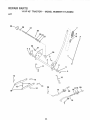
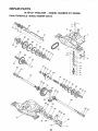
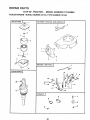
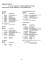
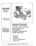
MODEL NUMBER 917.254850
Assembly
• Operation
• Customer
Responsibilities
oService
oAdjustments
o Repair Parts
Caution:
Read and Follow
all Safety Rules
and Instructions
Before Operating
This Equipment
OWNER'SMANUAL
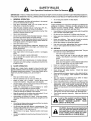
SAFETY
Practices RULES
for Ride-On
Safe Operation
Mowers
IMPORTANT: THIS CUTTING MACHINE IS CAPABLE OFAMPUTATING HANDS AND FEET AND THROWING OBJECT&
FAILURE TO OBSERVE THE FOLLOWING SAFETY INSTRUCTIONS COULD RESULT IN SERIOUS INJURY OR DEATH.
I.
GENERAL OPERATION
•
Read, understand, and follow alt instructions in the manuat
and on the machine before starting..
Onty allow responsible adults, who are familiar with the
instructions, to operate the machine.
Clear the area of objects such as rocks, toys, wire, etc.
which could be picked up and thrown by the blade.
Be sure the area is clear of other people before mowing Stop
machine if anyone enters the area.,
•
•
•
•
Do not use grass catcher on steep slopes..
IlL
CHILDREN
Tragic accidents can occur if the operator is not alert to the
presence of children.
Children are often attracted to the
machine and the mowing activity.
Never' assume that
children will remain where you last saw them.
•
Keep children out of the mowing area and under the watchful
care of another responsible adult.
Be alert and turn machine off if children enter the area.,
°
•
Never carry passengers.
Do not mow in reverse unless absolutely necessary.. Always
look down and behind before and while backing.
•
°
Before and when backing, look behind and down for small
children..
°
Be aware of the mower discharge direction and do not point
it at anyone. Do not operate the mower without either the
entire grass catcher or the guard in place_
Slow down before turning.
Never leave a running machine unattended. Atways turn off
blades, set parking brake, stop engine, and remove keys
before dismounting
Turn off blades when not mowing.
Stop engine before removing grass catcher or unclogging
chute..
°
Never carry children. They may fall off and be seriously
injured or interfere with safe machine operation..
Never allow children to operate the machine..
Use extra care when approaching blind corners, shrubs,
trees, or other objects that may obscure vislon_
•
•
°
°
•
°
•
•
!1.
°
°
IV.
SERVICE
•
Use extra care in handling gasoline and other fuets_ They are
flammable and vapors are explosive,
Mow only in daylight or good artificial light
Do not operate the machine while under the influence of
alcohol or drugs,
Watch for traffic when operating near or crossing roadways
Use extra care when loading or unloading the machine into
a trailer or truck.
SLOPE
•
OPERATION
•
Slopes are a major factor related to toss-of-control
and
tipover accidents, which can result in severe injury or death.
AI! slopes require extra caution,
tf you cannot back up the
slope or' if you fee! uneasy on it, do not mow it.
•
•
DO:
°
°
•
•
°
°
°
°
Mow up and down slopes, not across_
Remove obstacles such as rocks, tree limbs, etc
Watch for hotes, ruts, or bumps.
Uneven terrain could
overturn the machine. Tall grass can hide obstacles
Use slow speed. Choose a low gear so that you will not have
to stop or shift while on the slope.
Follow the manufacturer's
recommendations
for wheel
weights or counterweights to improve stability..
Use extra care with grass catchers or other attachments,
These can change the stability of the machine
Keep all movement on the slopes sfowand gradual. Do not
make sudden changes in speed or direction.
Avoid starting or stopping on a slope, tf tires lose traction,
disengage the blades and proceed slowly straight down the
slope
•
•
•
•
•
DO NOT:
o
o
°
•
Use only an approved container_
Never remove gas cap or add fuel with the engine
running Allow engine to cool before refueling Do not
smoke
Never refuel the machine indoors.
Never store the machine or fuel container inside where
there is an open flame, such as a water heater..
Never run a machine inside a dosed area_
Keep nuts and boits, especially blade attachment bolts, tight
and keep equipment in good condition
Never tamper with safety devices.
Check their proper
operation regulady_
Keep machine free of grass, leaves, or other debris build-up.
Clean oil or fuel spitiage
Allow machine to cool before
storing
Stop and inspect the equipment if you strike an object..
Repair, if necessary, before restarting,
Never make adjustments or repairs with the engine running_
Grass catcher components are subject to wear, damage, and
deterioration, which could expose moving parts or allow
objects to be thrown. Frequently check components and
replace with manufacturer's recommended parts, when necessary
Mower blades are sharp and can cut. Wrap the blade(s) or
wear gloves, and use extra caution when servicing them_
Check brake operation frequently. Adjust and service as
required.
A,
Do not turn on slopes unless necessary, and then, turn slowly
and gradually downhill, if possible..
Do not mow near drop-offs, ditches, or embankments. The
mower could suddenly turn over if a wheel is over the edge
of a cliff or ditch, or if an edge caves in.
Do not mow on wet grass. Reduced traction could cause
sliding.
Do not try to stabilize the machine by putting your foot on the
ground.
tant safety precautions.
It means
CAUTIONI!t
BECOME
ALERTV, tt
YOUR
Look
for this
symbol to point out imporSAFETY
IS INVOLVED.
CAUTION: Always disconnect sparkplug
wire and place wire where it cannot contact spark plug in order to prevent accidental starting when setting up, trans_
porting, adjusting or making repairs,
2
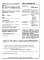
CONGRATULATIONS
on your purchase of a Sears
Tractor,, It has been designed, engineered and manufactured to give you the best possible dependability and
performance,
PRODUCT
Should you experience any problem you cannot easily
remedy, please contact your nearest Sears Service
CentedDepartmento
We have competent, well-trained
technicians and the proper tools to service or repair this
uniL
Please read and retain this manual The instructions wilt
enable you to assemble and maintain your unit properly,,
Always observe the "SAFETY RULES",
SPECIF CATIONS
HORSEPOWER:
14
GASOLINE CAPACITY:
5 QUARTS
UNLEADED
REGULAR
OIL (35 PINTS W/O FILTER):
(4,0 PINTS WlFILTER):
SAE 30 (Above 32°F)
SAE 5W-30 (Below 32°F)
SPARK PLUG (GAP030
CHAMPION
IN,):
RC-12YC
VALVE CLEARANCE:
iNTAKE ,,0015 - ,0030 IN.
EXHAUST ,0020- :0035 IN.,
GROUND SPEED:
FORWARD
1st 1o10 MPH
2nd 1_40 MPH
3rd 2.00 MPH
4th 3,,00 MPH
5th 4,,20 MPH
6th 5,00 MPH
REVERSE: 1o50 MPH
THE MODEL AND SERIAL NUMBERS WILL BE FOUND
ON A PLATE UNDER THE SEAT,,
TIRE PRESSURE:
FRONT: 14 PSI
REAR: 12 PSI
YOU SHOULD RECORD BOTH SERIAL NUMBER AND
DATE OF PURCHASE AND KEEP IN A SAFE PLACE
FOR FUTURE REFERENCE°
CHARGING SYSTEM:
3 AMPS BATTERY
5 AMPS HEADLIGHTS
BLADE BOLT TORQUE:
30-35 FT_ LBS,,
MODEL
NUMBER
917°254850
SERIAL
NUMBER
DATE OF PURCHASE
MAINTENANCE
AGREEMENT
A Sears Maintenance
Agreement
ucto Contact your nearest Sears
CUSTOMER
WARNING:
This unit is equipped with an internal combustion engine and should not be used on or near any unimproved forest-covered,
brush-covered
or grass-covered
rand unless the engine's exhaust system is equipped with
a sp.ark arrester meeting applicable
local or state laws {if
any),, ITa spark arres_er Js usea, i[ snould be maimainea _n
effective working order by the operator.,
is available on this prodstore for details,,
RESPONStBILITIES
.
Read and observe
the safety
rules.
°
Follow a regularschedule
using your unit,,
°
Follow the instructions
under "Customer Responsibilities" and "Storage"
sections of this owner's manual.
in maintaining,
In the state of California
the
(Section 4442 of the California
Other states may have similar
federal lands, A spark arrester
through your nearest Sears
(See REPAIR PARTS section
caring for and
above is required
by law
Public Resources
Code).
laws,, Federal laws apply on
for the muffler is available
Authorized
Service
Center
of this manua0.
iiii
Lt /ilTED
TWO YEAR WARRANTY
ON ELECTRIC
/
iin ............................
,..............
START RIDING EQUIPMENT
For two (2) years from the date of purchase, if this riding equipment is maintained, lubricated and tuned up according to the
instructions in the owner's manual, Sears will repair or replace, free of charge, any parts found to be defective in material or
workmanship,,
This Warranty does not cover:
*
.
.
Expendable items which become worn during normal use, such as blades, spark pEugs, air cleaners and belts°
Tire replacement or repair caused by punctures from outside objects, such as nails, thorns, stumps, or gJass,,
Repairs necessary because of operator abuse, negligence, improper storage or accident or the failure to maintain the
equipment according to the instructions contained in the owner's manual
Riding equipment used for commercial or rental purposes.
LIMITED 90 DAY WARRANTY
ON BATTERY
For 90 days from date of purchase, if any battery inctuded with this riding equipment proves defective in material or workmanship
and our testing determines the battery will not hold a charge, Sears will replace the battery at no charge.
WARRANTY SERVICE
CENTER/DEPARTMENT
IS AVAILABLE BY RETURNING
IN THE UNITED STATES,
THE RIDING EQUIPMENT
TO THE NEAREST
SEARS SERVICE
This Warranty gives you specific legal rights, and you may also have other rights which may vary from state to state
SEARS,
.........................................................
ROEBUCK
hi,
i
AND CO,,, D/817 WA, HOFFMAN
i
'
:::
ESTATES,
...........
3
ILLINOIS
60179
:::
i,,,i
:,
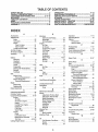
TABLE OF CONTENTS
SAFETY RULES ............................................................
2
PRODUCT SPECIFICATIONS
...................................... 3
CUSTOMER RESPONSIBILITIES ..................... 3, 15-19
WARRANTY ..................................................................
3
TABLE OF CONTENTS ................................................
4
INDEX .....................................................
;...................... 4
TRACTOR ACCESSORIES ..........................................
5
ASSEMBLY ..............................................................
7-10
OPERATION ..........................................................
:I 1.14
MAINTENANCE SCHEDULE ......................................
15
SERVICE AND ADJUSTMENTS ............................ 20-25
STORAGE ...................................................................
26
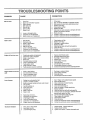
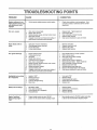
TROUBLESHOOTING
...........................................
27-28
REPAIR PARTS - TRACTOR ................................ 30-47
REPAIR PARTS - ENGINE .................................... 48-53
PARTS ORDERING/SERVICE
.................. BACK PAGE
itNDEX
4
Operation .....................................................
1!-14
Operating Mower .............................................
13
Options:
Accessories ..................................................
5
Spark Arrester. ..................................
3,40
P
Parking Brake .........................................
11-12
Parts Bag ....................................................................
6
Parts, Replacement/Repair
...............
30-47
Product Specifications .........................................
3
R
Repair Parts ....................................................
30-47
S
Safety Rules .................................................................
2
Seat ......................................................................
8
Service and Adjustments .......................
20-25
Carburetor ....................................................
25
Fuse
24
Hood Removal/InstaUation
................
23
Motion Ddve Belt
Removal/Replacement
................
22
Mower Blade Drive Belt
RemovaltReplacement
.................
22
Mower Adjustment
Front- to-Back ..............................
2!
Side-to-Side ....................................
21
Mower Removal ....................................
20
Tire Care ..........................................
8,16,23
Slope Guide Sheet ......................................
55
Spark Plugs .......................................................
19
Specifications ..............................................................
3
Starting the Engine ..............................
13-14
Steering Wheel .............................................
7,23
Stopping the Tractor ....................................
12
Storage ...................................................................
26
..............................................................
A
E
Accessories .................................................................
5
Electrical:
Adjustments:
Interlocks and Relays ...........................
24
Brake .........................................................
22
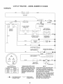
Schematic ...............................................
29
Carburetor, ......................................................
25
Widng Diagram ....................................
30
Mower
Engine:
Front-To-Back ......................................
21
Air Filter .......................................................
t8
Side-To-Side ................................21
Air Screen .................................................
18
"l"hrottle Control Cable .........................
25
Cooling Fins, Engine ..........................
18
Air Filter, Engine .............................................
18
Oil Change ..............................................
17
Air Screen, Engine .........................................
18
Oi! Level ...............................................
13,17
Assembly ...........................................................
7-10
Oil Type .....................................................
17
B
Preparation ..................................................
13
Repair Parts .....................................
48-53
Battery:
Charging .......................................................
8
Starling .......................................................
14
Cleaning .........................................................
17
Storage ......................................................
26
installation ........................................................
9
F
Levels .................................................
8,17
Filter:
Air Filter ....................................................
18
Preparation .................................................
8
Fuel ..............................................................
19
Starting with Weak Battery ............23
Storage ..........................................................
26
Fuel:
Terminals .....................................................
17
Type ............................................................
13
Belt:
Storage ........................................................
26
Motion Drive
Fuse .......................................................................
24
Removal/Replacement
................
22
H
Mower Blade Drive
Hood Removal/Installation
.................24
Removal/Replacement
...............
22
L
Blade:
Leveling Mower Deck ................................
21
Sharpening ..................................................
16
Lubrication:
Replacement .............................................
16
Chart .........................................................
15
Brake Adjustment ...........................................
22
M
C
Maintenance Schedule .................................
15
CarburetorAdjustment
................................
25
Mower:
Controls, Tractor ..............................................
11
Adjustment, Front-to-Back .............21
Customer Responsibilities ..................
15-19
Adjustment, Side-to-Side .................
21
Engine:
Blade'Sharpening
..............................
16
Air Filter .............................................
18
Blade Replacement ................................
16
Air Screen, Engine ...........................
18
Cutting Height ........................................
12
Battery .................................................
17
Installation .................................................
20
Cooling Fins, Engine ......................
18
Operation .....................................................
13
Engine Oil ..............................................
17
Removal ...............................................
20
Fuel Filter ...........................................
19
Mowing Tips ..................................................
14
Spark Plugs .........................................
19
Muffler, ..................................................................
19
Tractor:
Spark Arrester .................................
3,40
Blade ..........................................................
16
Mulcher Plate ...........................................
10
Lubrication Chart ...............................
15
O
Maintenance Schedule ..................
15
Oil:
Tire Care .......................................
8,16,23
Cold Weather Conditions ...........
13,17
Cutting Height, Mower .............................12
Engine .................................................
17
Storage ........................................................
26
T
Throttle Control Cable
Adjustment ................................................
25
Tires .......................................................................
8,16,23
Trouble Shooting Chart .......................
27-28
Transaxle:
Repair Parts ........................................
46-47
W
Warranty .................................................................
3
WMng Diagram ....................................................
30
Wiring Schematic ..................................................
29
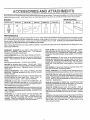
ACCESSO
- ..........
..................
.......
ATTACHMENTS
BESA
,i,,, i ,,11
....
1_
..............
These accessories and attachments were available when the tractor was purchased
catalog and service centers
They are also available at most Sears retail outlets,
Most Sears stores can order these items for you when you provide the model number of your tractor
ENGINE
_ARKPLUG
MAINTENANCE
MUFFLER
........
AIR FILTER
r
GAS CAN
ENGINE OIL
STABILIZER
BLADES
BELTS
, ,,,,, .....
........
Ft.
PERFORMANCE
Sears offers a wide variety of attachments that fit your tractor,
you This list was current at the time of publication; however,
may be made in these attachments, or some may no longer
accessories
and attachments
that are available for your
Most of these attachments
attaching and detaching
Many of these are listed below with brief explanations of how they can help
it may change in future years - more attachments may be added, changes
be available or fit your model Contact your nearest Sears store for the
tractor.
do net require additional hitches or conversion kits (those that do are indicated) and are designed for easy
PERMANEX
BAGGER lets you collect grass clippings and
leaves for a healthier, heater looking lawn
Two Permanex
containers hold 30-gallon plastic bags.
LAWN SWEEPERS
let you collect grass clippings and leaves
LAWN VACS for powerful collection of heavy grass clippings and
leaves
Wand attachment to pick up debris in hard4o-reach
places
CARTS make hauling easy Variety of sizes available.
ROLLER for smoother lawn surface.
36-inch wide, 18-inch
diameterwater4ight
drum hotds up to 390 fbs of weight Rounded
edges prevent harm to turf Adjustable scraper automatically
cleans drum
SNOW BLADE for snow removal only
144nch high, 42-inch
wide blade clears 38-inch path when angled left or right Raises,
lowers with side lever, Adjustable skids; replaceable, reversible
scraper bar. (Use with tire chains, wheelweights, or rear drawbar
weight.)
SNOWTHROWER has40-inchswath
Drum4ypeaugerhandles
powdery and wet/heavy snow. Mounts easily with simple pin
arrangement, Discharge chute adjusts from tractor seat 6-inch
diameter spout discharges snow 10 to 50 feet Lift controlled at
tractor seat (Use with chains, wheel weights, or rear drawbar
weight.)
TIRE CHAINS are heavy duty; closely spaced extra-large cross
links give smooth ride, outstanding traction
make seeding, fertilizing, and weed
spreaders are also usefut for granular
WHEEL WEIGHTS for rear wheels provide needed traction for
snow removal or dozing heavy materials° in pairs (30 lbs, each,)
CORING AERATOR takes small plugs out of soil to allow moisture and nutrients to reach grass roots
364nch swath
24
hardened steel coring tips_ 150 Ib capacity weight tray.
TRACTOR CAB has heavy duty vinyl fabric over tubular steel
frame, ABS plastic top; clear plastic windshietd offers 360 degree
visibility Hinged metal doors with catch. Keeps operator warm
and dry Remove vinyl and windshields for use as sun protector
in summer (Catalog only,)
SPREADERISEEDERS
killing easy Broadcast
de-icers and sand,
AERATOR promotes deep root growth for a healthy lawn Tapered 2,5-inch steel spikes mounted on 10-inch diameter discs
puncture holes in soil at close intervals to let moisture soak in
Steel weight tray for increased penetration
MULCH RAKE/DETHATCH
ER loosens soil and flips thatch and
matted leaves to lawn surface for easy pickup Twenty spring tine
teeth. Useful to prepare bare areas ferseeding Available forfrent
or rear mounting
SPRAYERS use 12-volt DC electric motor that connects to the
tractor battery or other 12-volt source,
includes booms for
automatic spraying when pulling, and hand held wand for spot
spraying
Wand has adjustable spray pattern
For applying
herbicides, insecticides, fungicides, and liquid fertilizers
Optional accessories
for tractor cab: tinted/tempered
solid
safety glass windshield with hand operated wiper; 12-volt amber
caution light for mounting on cab top. (Catalog only..)
TRACTOR COVER protects tractor from weather.
Made of
Evolution 3 fabric (water-repellent,
extremely breathable, light
weight, soft, non-abrasive, pliable in all temperatures, durable,
stain/teadpuncture
resistant, will not shrink or stretch,.) (Catalog
only)
TILLER has 5 hp engine and 36-inch swath to prepare seed beds,
cultivate, and compost garden residue, Tiller has its own built-in
lift and depth control system and does NOT require a sleeve hitch
Fits any lawn, yard, or garden tractor
Simply hook up to the
tractor drawbar and go!
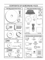
CONTENTS OF HARDWARE PACK
............
i ....
i....
Parts Bag contents
=
.............. ,,,,
.......
_.........
II'_lL'L'l'
'1
shown full size
..r,
...........
©
Parts packed
separately
in carton
,....
(2) Sheet
Metal
Seat
Battery acid
Screws
#10-16 x 1/2
Mulcher
Plate
Steering
Wheel
(1) Shoulder Bolt 5/16-18
(1) Hex Bolt 1/2-13 x !
@
(1) Lock Washer
(!)
Steering
Boot
Owner's Manual
.........
iHll
Parts Bag
i,, i,
i......................................
Parts bag contents
1/2
©
Washer' 17/32 x 1-3/16 x i2 Gauge
(2) Shoutder
Bolts
(2) Screws
#10 x 5/8
(2) Lock Washers
(2) Weld Nuts #10 _
(2) Washers
3/16 x 3/4 x 16 Gauge
not shown full size
(2) Locknuts
3/8-16
(2)
Wheels
Gauge
#10
Steering
,Wheel
Insert
Steering Wheel
Adapter
I
LJ
_
Bushing
teering
..................
_(2)
Latch Ho-__ok
Assemblies
(2) Hex Bolts 1/4-20 x 3/4
!
i'
1
(2) Keys
J
i
(2) Hex Nuts 1/4-20
(2) Washers
9/32 x 5/8 x 16 Gauge
(2) Lock Washers
1/4
15° Slope Sheet
Battery Caps
and Instructions
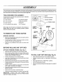
ASSEM
LY
Your new tractor has been assembled at the factory with exception of those parts left unassembled for shipping purposes.
To ensure safe and proper operation of your tractor all parts and hardware you assemble must be tightened securely., Use
the correct tools as necessary to insure their proper tightness.
TOOLS
REQUIRED
FOR ASSEMBLY
A socket wrench set will make assembly easien Standard
wrench sizes are listed°
(1) 5/16" wrench
Tire pressure gauge
(2) 7/16" wrenches
Phillips Screwdriver
(1) 9/16" wrench
Utility knife
(1) 3/4" socket & drive ratchet
(1) i/2" wrench
WHEEL
TO REMOVE
UNPACK
STEERING
BUS}
STEERING
When right and left hand is mentioned in this manual, it
means when you are in the operating position (seated
behind the steering wheel),
ADAPTER
WHEEL
"__
SCREW
=
STEERING
UNIT FROIVi CARTON
CARTON
,__ABS,
SHAFT
o
Remove alt accessible loose parts and parts cartons
from carton (See page 6).
o
Cut along lines on carton, from top to bottom, all four
corners of carton and lay panels flat.
•
Check for any additional
remove..
(ASSEMBLY
POSITION)
TAB
/
loose parts or cartons and
/
SLOT
BEFORE
ROLLING
STEERIN
SHAFT
UNIT OFF SKID
.....
"_-.
....
, ,
' '
(SHIPPING
POSITION)
ATTACH
STEERING
WHEEL
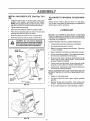
(See Fig. 1)
FIG. 1
,
Slide the steering bushing over the steering shaft.
o
Raise steering shaft forward until screw holes in dash
line up with steering bushing. Install two (2) sheet
metal screws and tighten securely°
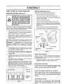
TO ROLL UNIT OFF SKiD (See Fig. 8)
=
Position steering boot over steering shaft.
-
Raise attachment lift lever to its highest position,,
°
Align tabs of steering boot over slots and hole in dash
and push down to secure.
°
Release parking brake by depressing
pedal.
°
Slide steering wheel adapter onto upper steering shaft°
.
Position front wheels of the tractor so they are pointing
straight forward.
o
,
Place gearshift lever in "NEUTRAL" position.
Roll unit backwards off skid,
-
o
Position steering wheel so cross bars are horizontal
(left to right) and slide onto adapter,,
Remove banding holding discharge guard up against
tracton
o
Assemble large flat washer and 3/8-24 hex locknut and
tighten securely,
°
Snap insert into center of steering wheel.
o Remove protective plastic from tractor hood and grill,
IMPORTANT:
CHECK
FOR AND REMOVE
ANY
STAPLES IN SKiD THAT MAY PUNCTURE Tl RESWHERE
UNIT iS TO ROLL OFF SKID,
clutchtbrake
LY
:=:
_:
:
i .....
i ..
i.
.
ill..
HOW TO SET UP YOUR TRACTOR
PREPARE
BATTERY
............ii
iill...lll,,
i
INSTALL
,.I.IHlll
.m.
SEAT (See Fig. 3)
Adjust seat before tightening adjustment bolt.
(See Fig. 2)
CAUTION: Wear eye and face shield.
Wash hands or clothing immediately if
accidentally in contact with battery acid,
Do not smoke. Fumes from charged
battery acid are explosive. Read the
instructions
included with the battery
vent caps. Always wear gloves, clothing and goggles to protect your' hands,
skin and eyes.
Your unit has a battery charging system which is sufficient
for normal use_ However', periodic charging of the battery
with an automotive charger will extend its life
*"
See instructions packed with vent caps in parts bag..
=
Fill battery with acid_ Fill each cell until it reaches the
bottom of the vent wells._ Do not overfill
=
Remove cardboard packing on seat pan.
=
Place seat on pan and assemble shoulder' bolt.,
o
Assemble adjustment bolt, iockwasherandflatwasher
loosely, Do not tighten.
o
Tighten shoulder bolt securely..
•
Lower seat into operating position and sit on seal
=
Slide seat until a comfortable position is reached which
allows you to press clutch/brake pedal all the way down
(See Fig. 8).
o
Get off seat without moving its adjusted position,.
o
Raise seat and tighten adjustment bolt securety_
SEAT
SEAT PAN
Allow battery to stand and settle for at least thirty
minutes.. After standing, check the level of acid_ if
below the vent wells, add more acid until the correct
level is reached.
SHOULDER
BOLT
While battery is standing (after adding acid) and later, while
battery is being charged, continue with assembly of uniL
IMPORTANT:
TO MAXIMIZE THE LIFE OF YOUR
BATTERY, IT tS NECESSARY THAT THE BATTERY BE
CHARGED
BEFORE USE. FAILURE TO CHARGE
BATTERY CAN RESULT IN A SHORTENED BATTERY
LIFE,
o
,
Check the acid level after' the battery is charged. If the
acid has fallen below the correct level, add distilled or
iron free water,
o
Install the vent caps to cover the vent wells, Wash the
top of the battery with water to remove any acid, then
wipe dry.
o
Check battery case for leakage to make sure that no
damage has occurred in handling,.
°
Dispose of excess battery acid. Neutralize acid for
disposal by adding it to four inches of water in a five
gallon plastic container. Stir with a wooden or plastic
paddle while adding baking soda unti! the addition of
more soda causes no more foaming.
°
FLAT WASHER
Charge battery at a rate of 6 amperes for i hour. Use
a 12 volt battery charger,. Observe all safety precautions required for' battery charging.
Follow instructions
on how to install battery..
ADJUSTMENT
BOLT
LOCK WASHER
FIG. 3
CHECK TIRE PRESSURE
The tires on your unit were overinflated at the factory for
shipping purposes, Correct tire pressure is important for
best cutting performance°
o
Reduce tire pressure to PSI shown in "PRODUCT
SPECIFICATIONS" on page 3 of this manual.
CHECK DECK LEVELNESS
For best cutting results, mower housing should be properly
leveled. See "TO LEVEL MOWER HOUSING" in the
Service and Adjustments section of this manual
CUT AWAY VIEW
CHECK FOR PROPER POSITION OF ALL BELTS
C
VENT WELL
VENT CAP
BATTERY
CELL ACID
LEVEL
See the figures that are shown for replacing motion and
mower blade drive belts in the Service and Adjustments
section of this manual
Verify that the belts are routed
correctly.
CHECK BRAKE SYSTEM
FIG. 2
After you learn how to operate your tractor, check to see
that the brake is properly adjusted° See "TO ADJUST
BRAKE" in the Service and Adjustments section of this
ASSEMBLY
iNSTALL
BATTERY
(See Figs. 4 & 5)
CAUTION: Do not short battery terminals. Before installing battery, remove
metal bracelets,
wristwatch
bands,
rings, etc.
Positive terminal must be connected
first to prevent sparking from accidental grounding.
o
Lift seat to raised position
°
Open battery box door°
•
Lower battery into battery box with battery terminals
toward front of unit
°
Be sure battery drain tube is attached to battery box
o
First connect RED battery cable to positive (+) battery
terminal with hex bolt, flat washer, tock washer and hex
nut as shown Tighten securely
o
Connect BLACK grounding cable to negative (-) battery terminal with remaining hex bolt, flat washer, lock
washer and hex nut° Tighten securely°
o
BATTERY
BOX DOOR
VENT CAPS
Close battery box door_
FIG. 5
Open battery box door for:
o
inspection
ware)°
for secure connections
o
inspection for corrosion
o
Testing battery°
o
Jumping (if required).,
•
Periodic charging _
(to tighten hard_
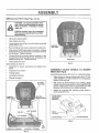
ASSEMBLE
GAUGE
DECK (See Fig.6)
WHEELS
TO
MOWER
Assemble gauge wheels with tractor on a flat level surface°
BATTERY
BOX DOOR
POSITIVE
(RED) CABLE
-
Adjust mower to desired cutting height (See "TO ADJUST MOWER CUTTING HEIGHT" in the Operation
section of this manual)
.
With mower in desired height of cut position, gauge
wheels should be assembled so they are slightly off the
ground Install gauge wheel in appropriate hole with
shoulder bolt and !ocknut and tighten securely
o
Repeat for opposite side installing
same adjustment hole
gauge wheel in
NEGATIVE
(BLACK) CABLE
3/8-16
LOCKNUT_
GAUGE WHEEL--
__.._
FIG. 6
BOLT
POSITIVE
(+) TERMINAL
NEGATIVE
FIG. 4
(-) TERMINAL
SHOULDER
BOLT
ASSEMBLY
INSTALL
7B)
IVlULCHER
PLATE
(See Figs. 7A &
o
Install two latch hooks, to mulcher plate using screw,
washer, lock washer, and weld nut as shown
NOTE: Pre-assemble weld nut to latch hook by inserting weld nut from the top with hook pointing down°
o
Tighten hardware securely
o
Raise and hold deflector shield in upright position
°
°
Place front of mulcher plate over front of mower deck
opening and slide into place, as shown
Hook front latch into hole on front of mower deck
o
Hook rear latch into hole on back of mower deck.
t_,
e_&j_
I
I
it to rest on plate while in operation.
I
OR DISCHARG-
Simply remove mulcher plate and store in a safe place.
Your mower is now ready for discharging or installation of
optional grass catcher accessory
BEFORE YOU OPERATE AND ENJOY YOUR NEW
TRACTOR, WE WISH TO ASSURE THAT YOU RECEIVE
THE BESTPERFORMANCEAND
SA TISFACTION FROM
THIS QUALITY PRODUCT
PLEASE REVIEW THE FOLLOW!IVG CHECKLIST:
,/
All assembly instructions have beer] completed
v"
No remaining loose parts in carton
J
Batteryis properly prepared and charged
1 hour at 6 amps)
,I
Seat is adjusted comfortably and tightened securely_
HOOK POINTS
(Minimum
,." All tires are properly inflated (For shipping purposes,
the tires were overinflated at the factory)
LOCK
WASHER
WELD
TO BAGGING
vr CHECKL IS T
CAUTION: Do not remove discharge
guard from mower. Raiseand hold guard
when attaching mulcher plate and allow
WELD NUT
FROM THE TOP
TO CONVERT
ING
v"
Be sure mower deck is properly leveled side-to-side/
front-to-rear for best cutting resultso (Tires must be
properly inflated for leveling).
,/
Check mower and drive belts Be sure they are routed
properly around pulleys and inside all belt keepers°
HOOK
LATCH
HOOK
LOCK
WASHER
MULCHER
PLATE
WASHER
WELD
NUT
_SCREW
,t" Check wiring. See that all connections are still secure
and wires are properly clamped
WHILE LEARNING HOW TO USE YOUR TRACTOR, PAY
EXTRAA TTENTION TO THE FOLLOWING IMPORTANT
ITEMS:
v'
Engine oil is at proper level
,/
Fuel tank is filled with fresh, clean, regular unleaded
gasoline
Become familiar with all controls - their location and
function_ Operate them before you start the engine.
v'
FIG, 7A
,/
DEFLECTOR
SHIELD
LATCH
HOOKS
FIG. 7B
Be sure brake system is in safe operating condition.
KNOW YOUR TRACTOR
READ THiS OWNER'S
MANUAL
AND SAFETY
RULES
BEFORE
OPERATING
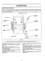
Comparethe illustrationswithyour tractorto familiarize yourself with the locations of variouscontrolsand
this manual for future reference°
ATTACHMENT
CLUTCH
YOUR TRACTOR
adjustmentso Save
LEVER
LIFT LEVER
PLUNGER
LIGHT SWITCH
THROTTLE!CHOKE
CONTROL
ATTACHMENT
LIFT LEVER
CLUTCHIBRAKE
PEDAL
HEIGHT
KNOB
GEARSHIFT
LEVER
ADJUSTMENT
PARKING
IGNITION
SWITCH
BRAKE
FIG. 8
Sears tractors conform to the safety standards of the American National Standards Institute,,
GEARSHIFT LEVER: Selects the speed and direction of
tractor.
ATTACHMENT CLUTCH LEVER: Used to engage the
mower blades, or other attachments mounted to your
tractor.
LIGHT SWITCH:
ATTACHMENT LIFT LEVER: Used to raise and lower the
mower deck or other attachments mounted to your tractor.
Turns the headlights on and off°
THROTTLE/CHOKE
CONTROL:
controlling engine speed.
LIFT LEVER PLUNGER: Used to release attachment lift
lever when changing its position.
Used for starting and
CLUTCH!BRAKE PEDAL: Used for declutching and braking the tractor and starting the engine°
IGNITION SWITCH:
engine.,
PARKING BRAKE:
brake position°
HEIGHT ADJUSTMENT
cutting height°
Locks clutch/brake
pedal into the
't'1
Used for starting and stopping the
KNOB: Usedto adjust the mower
The operation of any tractor can result in fo reign objects thrown into the eyes, which can result
in severe eye damage. Always wear safety glasses or eye shields while operating your tractor
or performing any adjustments or repairs. We recommend wide vision safety mask for over
the spectacles or standard safety glasses, available at Sears Retail or Catalog stores..
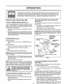
TO MOVE FORWARD
HOW TO USE YOUR TRACTOR
AND BACKWARD
(See Fig. 9)
TO SET PARKING
BRAKE
(See Fig. 9)
The direction and speed of movement is controlled by the
gearshift lever.
Your unit is equipped with an operator presence sensing
switch,. When engine isrunning,
any attempt by the
operator to leave the seat without first setting the parking
brake will shut of the engine,.
o
Depress clutch/brake
and holdo
pedal into full "BRAKE" position
Start tractor with clutch/brake pedal depressed
gearshift lever in "NEUTRAL" position.
,
Move gearshift
(See Fig. 9)
leverto desired position..
ATTACHMENT
CLUTCH LEVER
"ENGAGED"
POSITION
THROTTLE/CHOKE
CONTROL
MOWER BLADES *
Move attachment clutch lever to "DISENGAGED"
sition.
and
,
Slowly release clutch/brake pedal to start movement.
IMPORTANT: BRING TRACTOR TOA COMPLETE STOP
BEFORE SHIFTING OR CHANGING GEARS. FAILURE
TO DO SO WILL SHORTEN THE USEFUL LIFE OF YOUR
TRANSAXLE
Place parking brake lever in "ENGAGED" position and
release pressurefrom clutch!brake pedal° Pedal should
remain in "BRAKE" position. Make sure parking brake
will hold vehicle secure.
STOPPING
,
poRKING BRAKE
GROUND DRIVE-
'ENGAGED"
•
Depress clutch/brake pedal into fuII"BRAKE" position.
°
Move gearshift lever to "NEUTRAL" positiOn.
POSITION
GEARSHIFT
LEVER
ENGINE o
Move throttle control to "SLOW"position.
"DISENGAGE!
POSITION
NOTE: Failure to move throttle control to "SLOW" position
and allowing engine to idle before stopping may cause
engine to "bacldire"_
,
o
HEIGHT ADJUSTMENT
Turn ignition key to "OFF" position and remove key.
Always remove key when leaving vehicle to prevent
unauthorized use°
Neveruse
KNOB
CLUTCH/BRAKE
PEDAL
"DRIVE" POSITION
FIG. 9
choke to stop engine.
TO ADJUST MOWER
(See Fig. 9)
NOTE: Undercertain conditions when unit is standing idle
with the engine running, hot engine exhaust gasses may
cause "browning" of grass,, To eliminate this possibility,
always stop engine when stopping unit on grass areas.
CUTTHNG HEIGHT
The cutting height is controlled by turning the height adjustment knob in desired direction.
CAUTION: Always stop unit completely,
as described above, before leaving the
operator's position; to empty grass
catcher, etc.
o
Turn knob clockwise (f1)
to raise cutting height.
,
Turn knob counterclockwise
heighL
(K"_) to lower cutting
Always operate engine at full throttle,,
The cutting height range is approximately 1-1/2" to 4". The
heights are measured from the ground to the blade tip with
the engine not running_ These heights are approximate
and may vary depending upon soil conditions, height of
grass and types of grass being mowed°
.
Operating engine at less than full throttle reduces the
battery charging rate..
o
°
Full throttle offers the best bagging and mower performance_
The average lawn should be cut to approximately 2_1/2
inches during the cool season and to over 3 inches
dudng hot month& For healthier and better looking
lawns, mow often and after moderate growth.
•
For best cutting performance, grass over 6 inches in
height_should be njowed !wice.L: Matje ,the first cut
TO USE THROTTLE
CONTROL
(See Fig. 9)
t'3
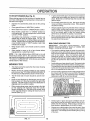
OPERATUON
TO OPERATE
MOWER
(See Fig. 10)
Your unit is equipped with an operator presence sensing
switch° Any attempt by the operator to leave the seat with
the engine running and the mower clutch engaged wilt shut
off the engine.
°
To restart movement, slowly release parking brake and
clutch/brake pedal..
o
Make all turns slowly..
o
Select desired height of cuL
TO TRANSPORT
°
Lower mower with attachment lift control.
o
Raise attachment lift control to highest position.
o
Start mower blades by engaging attachment
control
clutch
o
When pushing or towing your unit, be sure gearshift
lever is in "NEUTRAL" position.
o
TO STOP MOWER BLADES - disengage attachment
clutch control.,
°
Do not push or tow unit at more than five (5) MPH..
NOTE: To protect hood from damage when transporting
your tractor on a truck ora trailer, be sure hood is closed and
secured to tractor. Use an appropriate means of tying hood
to tractor (rope, cord, etc..).
CAUTION:
Do not operate the mower
without either the entire grass catcher,
on mowers so equipped, or the discharge guard in place.
ATTACHMENT CLUTCH LEVER
"DISENGAGED"
POSITION
"ENGAGED"
POSITION
BEFORE
CHECK
ATTACHMENT
LIFT LEVER
HIGH POSITION
LOW
POSITION
STARTING
ENGINE
THE ENGINE
OIL LEVEL
(See Fig, 16)
o
The engine in your unit has been shipped, from the
factory, already filled with summer weight oil..
°
Check engine oil with unit on level ground.
•
Unthread and remove oil fill cap/dipstick; wipe oil off..
Reinsert the dipstick into the tube and rest oil fill cap on
the tube. Do not thread the cap onto the tube. Remove
and read oif level If necessary, add oil until "FULL"
mark on dipstick is reached. Do not overfill..
•
For cold weather operation you should change oil for
easier starting (See "OIL VISCOSITY CHART" in the
Customer Responsibilities section of this manual).
°
To change engine oil seethe Customer Responsibilities section in this manual.
ADD GASOLINE
°
FIG. I0
TO OPERATE
IMPORTANT:
WHEN OPERATING
tNTEMPERATURES
BELOW 32°F(0°C), USE FRESH, CLEAN WINTER GRADE
GASOLINE
TO HELP INSURE GOOD COLD WEATHER
STARTING
ON HILLS
WARNING:
Experience indicates that alcohol blended
fuels (cal{ed gasohol or using ethanol or methanol) can
attract moisture which leads to separation and formation of
acids during storage. Acidic gas can damage the fuel
system of an engine whiie in storage. To avoid engine
problems, the fuel system should be emptied before storage of 30 days or longer. Drain the gas tank, start the
engine and let it run until the fuel lines and carburetor are
empty. Use fresh fuel next season° See Storage instructions for additional information..
Never use engine or
carburetor cieaner products in the fuel tank or permanent
damage may occur
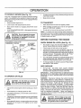
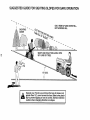
CAUTION:
Do not drive up or down
hills with slopes greater than 15 and
do not drive across any slope,
Choose the slowest speed before starting up or down
hills.
o
Avoid stopping or changing speed on hills.
o
If slowing is necessary, move throttle control lever to
slower position_
=
If stopping is absolutely necessary, push clutch/brake
pedal quickly to brake position and engage parking
brake.
Fill fuel tank..
Use fresh, clean, regular
unleaded
gasoline. (Use of leaded gasoline will increase carbon
and lead oxide deposits and reduce valve life)..
filler neck. Do not overfill Wipe offany
CAUTION:
bottom
of gas
spilled
oil orFill
fuel,to Do
not store,
spilltank
or
use gasoline near an open flame.
Move gearshift lever to 1st gear and be sure you have
allowed room for tractor to roll slightly as you restart
movement..
'13
OPERATI ON
TO START ENGINE (See Fig. 9)
When starting engine for the first time or if engine has run
out of fuel, it will take extra cranking time to move fuel from
the tank to the engine.
•
Depress the clutch/brake
brake.
pedal and set the parking
°
Place gearshift lever' in "NEUTRAL" position.
,
Move attachment clutch to "DISENGAGED"
o
Move throttle control lever' to "CHOKE" position for
cold engine start_ For warm engine start, move throttle
control to "FAST" position.
•
Turn ignition key clockwise to "START" position and
release key as soon as engine starts.. Do not run
starter continuously for more than fifteen seconds per
minute.. If engine does no! start afterseveral attempts,
move throttle control to FAST" position, wait a few
minutes and try again.
o
If grass is extremely tall, it should be mowed twice to
reduce load and possible fire hazard from dried clippings. Make first cut relatively high; the second to the
desired height,
°
Do not mow grass when it is wet,, Wet grass wil! plug
mower and leave undesirable clumps, Allow grass to
dry before mowing_
o
Always operate engine at fuil throttle when mowing to
assure better mowing performance and proper discharge of material.. Regulate ground speed by selecting a low enough gear to give the mower cutting
performance as wei! as the quality of cut desired.
•
When operating attachments, select a ground speed
that wilt suit the terrain and give best performance of
the attachment being used,,
position.
=
When engine starts, move throttle control to desired
position.
°
Allow engine to warm up for a few minutes before
engaging drive or attachment clutch..
MULCHING
The special rnulching blade will recut the grass clippings many times and reduce them in size so that as
they fall onto the lawn they will disperse into the grass
and not be noticed, Also, the mulched grass will
biodegrade quickly to provide nutrients for the lawn,
Always rnufch with your highest engine (blade) speed
as this will provide the best recutting action of the
blades,,
TaPS
o
Tire chains cannot be used when the mower housing
is attached to unit.
•
Mower should be properly leveled for best mowing
performance. See 'TO LEVELMOWER HOUSING" in
the Service and Adjustments section of this manual.
The left hand side of mower' should be used for-trimming,_
.
°
o
TIPS
IMPORTANT:
FOR BEST
PERFORMANCE,
KEEP
MOWER HOUSING
FREE OF BUILT-UP
GRASS AND
TRASH, CLEAN AFTER EACH USE,
NOTE: If at a high altitude (above 3000 feet) or in cold
temperatures (below 32 ° F), the carburetor fuel mixture
may need to be adjusted forbest engine performance. See
"TO ADJUST CARBURETOR" in the Service and Adjustments section of this manual.
MOWING
MOWING
°
Avoid cutting your lawn when it is wet,. Wet grass tends
to form clumps and interferes with the mulching action.
The best time to mow your' lawn is the early afternoon.
At this time the grass has dried and the newly cut area
will not be exposed to the direct sun,
o
Forbest results, adjustthe mowercutting height sothat
the mower' cuts off only the top one-third of the grass
blades (See Fig. 12)_ For extremely heavy mulching,
reduce your width of cut and mow slowly,,
Drive so that clippings are discharged onto the area
that has been cut. Have the cut area to the right of the
machine_ This will result in a more even distribution of
clippings and more uniform cutting,,
MAX 1/3
When mowing large areas, start by turning to the right
so that clippings will discharge away from shrubs,
fences, driveways, etco After one or two rounds, mow
in the opposite direction making left hand turns until
finished (See Fig. 1 t),.
FIG. 12
FIG. 11
14
o
Certain types of grass and grass conditions may require that an area be mulched a second time to completely hide the clippings. When doing a second cut,
mow across or perpendicular to the first cut path,
o
Change your cutting pattern from week to week. Mow
north to south one week then change 1oeast to west the
next week. This will help prevent matting and groining
of the iawn_
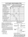
CUSTOMER
.....
Check Brake Operaiion
ESPO
LUTIlES
...................................................................
6#4
Check Tire Pressure
6#4
T
Check for Loose Fasteners
_
F{
/4
C
T
ShaipeniReplace Mowei Blades
0
R
Clean Battery and Terminals
.....
6#4 J
i
-
i .....
i i ......
i .........._#'4 ........................
Lubrication Chart
Check Battery Level/Recharge
i
6_
6#4
1
I
I_
v"
Check Transaxle Cooling
Adjust Blade Belt{s) Tension
Adjust Motion Drive Belt(s) Tension
....................
CheckEngine oil Level..................................
_ ....................
[_
Change EngineOil
.............
.....................................
6_1.2.3
_
Clean Air Filter
_1'2
Clean Air Screen
G
Inspect MuffledSpark Arrester
I
Replace Oil Filter (If equipped)
N
I
v'
Clean Engine Cooling Fins
Replace Spark Plug
v' e,'
Replace Air Filter Paper Cartridge
Replace Fuel Filter
1 _ Change more o!len when operating under a heavy Ioad or in high ambient
2 - Sewice mote often when operating in dirly or dusty conditions
GENERAL
v'
.{
temperatures
3 - If equipped with oil filter, change oil every 50 hours
4 - Replace blades more often when mowing in sandy soil
5 - If equipped with adjustable system
LUBRICATION
RECOMiVIEN DATIONS
@SPINDLE
The warranty on this tractor does not cover items that have
been subjected to operator abuse or negligence.
To
receive full value from the warranty, operator must maintain
tractor as instructed in this manual..
CHART
ZERK --
SPINDLE ZERK (_)
_NT WHEEL (_)
BEARING ZERK
Some adjustments wilt need to be made periodically to
properly maintain your tractor..
All adjustments in the Service and Adjustments section of
this manual should be checked at least once each season..
Once a year you should replace the spark plug, clean
or replace air filter, and check blades and belts for
wear.. A new spark plug and clean air filter assure
proper air4uel mixture and help your engine run better
and last longer°
BEFORE
EACH
ENGINE (_)
I
USE
o
Check engine oil level.
•
Check brake operation..
o
Checktire
pressure.
Check for loose fasteners.
GEARSHIFT
PIVOTS
(_
SAE 30 OR 10W30 MOTOR OIL API - SG
1_)
GENERAL
(_)
REFER TO CUSTOMER
(_)
PURPOSE GREASE
RESPONSIBILITIES
"ENGINE" SECTION
IMPORTANT:
DO NOT OIL OR GREASE
THE PIVOT POINTS
WHICH
HAVE
SPECIAL
NYLON
BEARINGS,
VISCOUS
LUBRICANTS
WILL ATTRACT
DUST AND DIRT THAT WILL
SHORTEN THE LIFE OF THE SELF-LUBRICATING
BEARINGS,,
IF YOU FEEL THEY MUST BE LUBRICATED,
USE ONLY A DRY,
_C_WthF'_'FI1 _R^PHITF
TYPF I URRICANT
SPARINGLY,
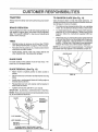
CUSTOMER
ESPONS BJLITIES
TRACTOR
TO SHARPEN
Always observe safety riJleswhen performing any maintenance,.
Care should be taken to keep the blade balanced. An
unbalanced blade wilt cause excessive vibration and eventual damage to mower and engine
BRAKE
OPERATION
If unit requires more than six (6) feet stopping distance at
high speed in highest gear, than brake must be adjusted.
(See "TO ADJUST BRAKE" in Service and Adjustments
section of this manual).,
TIRES
.
Maintain proper air pressure in all tires (See "PRODUCT SPECIFICATIONS"
on page 3 of this rnanual)_
•
Keep tires free of gasoline, oil, orinsect control chemicals which can harm rubber,.
o
Avoid stumps, stones, deep ruts, sharp objects and
other hazards that may cause tire damage.
BLADE (See Fig. 14)
.
The blade can be sharpened with a file or on a grinding
wheel. Do not attempt to sharpen while on the mower.
°
To check blade balance, you will need a 5/8" diameter
steel bolt, pin, or a cone balancer. (When using a cone
balancer, follow the instructions supplied with balancer).
o
Slide blade on to an unth readed portion of the steel bolt
or pin and hold the bolt or pin parallel with the ground.
If blade is balanced, it should remain in a horizontal
position If either' end of the blade moves downward,
sharpen the heavy end until the blade is balanced.
NOTE: Do not use a nail for' balancing blade. The lobes of
the center hole may appear to be centered, but are noL
CENTER HOLE
BLADE CARE
For best results mower blades must be kept sharp_ Replace bent or damaged blades,.
BLADE
REMOVAL
(See Fig. 13)
=
Raise mower to highest position to allow access to
blades.
°
Remove hex bolt, lock washer and fiat washer securing
blade.
•
Install new or resharpened
towards deck as shown_
•
Reassemble hex bolt, lock washer and flat washer in
exact order as shown_
OR PIN[___
FIG. 14
blade with trailing edge up
•
Tighten bolt securely (30-35 Ft.. Lbs., torque).
IMPORTANT: BLADE BOLT IS GRADE 8 HEAT TREATED.
NOTE: We do not recommend sharpening blade but if you
do, be sure blade is balanced°
(GRADE 8)*
*A GRADE 8 HEAT TREATED BOLT CAN BE
IDENTIFIED BY SIX LINES ON THE BOLT HEAD,
PI_
"lq
16
/
/
CUSTOMER RESPO
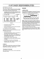
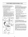
BATT'_RY
(See Fig. 15)
ENGmNE
Your unit has a battery charging system which is sufficient
for normal use., However, periodic charging of the battery
with an automotive charger will extend it's life,,
•
]LDTnES
LUBRICATION
Onty use high quality detergent oil rated with API service
classification SG. Select the oil's SAE viscosity grade
according to your expected operating temperature_
Acid solution level in each battery cell should be even
with bottoms of vent wells,, Add onty distilled or iron free
water if necessary. Do not overfill°
SAE VISCOSITY
CUT AWAY
VIEW
,j
GRADES
VENT CAP
rVENT
•..
.....
'_
__"" _:
WELL
:_F
BATTERY
CELL ACID
Keep battery and terminals clean,.
40 _
60"
80 '_
100 °
Check the crankcase oil level before starting the engine
and after each eight (8) hours of continuous use. Tighten
oil fill cap/dipstick securely each time you check the oii
level°
Recharge at 6 amperes for 1 hour.
-
Corrosion and dirt on the battery and terminals can cause
the battery to "leak" power,
o
Open battery box door..
o
Disconnect BLACK battery cable first then RED battery cable and remove battery from tractor..
.
Wash battery with solution of four tablespoons of
baking soda to one gallon of water_ Be careful not to get
the soda solution into the cells.
o
Rinse the battery with plain water and dry°
o
Clean terminals and battery cable ends with wire brush
until bright.
•
Coat terminals with grease or petroleum jelly_
o
Reinstall battery (See "INSTALL BATTERY"
Assembly section of this manual).
in the
V-BELTS
Check V-belts for deterioration and wear after 100 hours
and replace if necessary., The belts are not adjustable.
Replace belts if they begin to slip from wear.
TRANSAXLE
32 _
Change the oil after the first two hours of operation and
every 50 hours thereafter or at least once a year if the
tractor is not used for 50 hours in one year,,
Keepvent capstight and small vent holes in caps openo
TO CLEAN BATTERY AND TERMINALS
30 =
NOTE: Although multi-viscosity oils (5W30, t 0W30 etco)
improve starting in cold weather, these multi-viscosity oils
will result in increased oil consumption when used above
32°F. Check your engine oil level more frequently to avoid
possible engine damage from running low on oil
Keep battery bolts tight,
o
0_
TEMPERATURE RANGE ANTICIPATED BEFORE NEXT OIL CHANGE
FIG. 15
o
-20"
COOLING
Keep transaxle free from build-up of dirt and chaff which
can restrict cooling.,
17
TO CHANGE
ENGINE
OIL (See Fig. !6)
AIR FILTER
Determine temperature range expected before oil change.
All ol must meet API service classification SG
(See Fig.16)
Your engine will not run propedy using a dirty air filer.
Clean the foam pre-cteaner element after every25 hours of
operation or every season., Service paper cartridge every
100 hours or every season, whichever occurs first.
•
Be sure vehicle is on level surface..
o
=
Oil will drain more freely when warm.
Catch oil in a suitable container°
°
Remove oil fll dipstick.. Be careful not to alow dirt to
enter' the engine when changing oil
•
Remove drain plug..
o
After ol has drained completely, replace oil drain plug
and tighten securely.,
=
Slidefoam
.
Wash it in liquid detergent and water..
Refill engine with oil through oil fill dipstick tube° Pour
slowly.. Do not overfi!o For approximate capacity'see
Product Specifications on page 3 of this manual
=
Squeeze it dry in a clean cloth,
=
=
Service air' cleaner more often under dusty conditions.
=
pre-cleaner off cartridge.
.
Saturate it in engine oil.. Wrap it in clean, absorbent
cloth and squeeze to remove excess oil.
TO SERVICE CARTRIDGE
Use gauge on oil lilt dipstick for checking level. Insert
dipstick into the tube and rest the oil fil cap on the tube.
Do not thread the cap onto the tube when taking
reading° Keep oil at "FULL" line on dipstick. Tighten
cap onto the tube securely when finished.
°
Gently tap the flat side of the paper cartridge to dislodge dirt. Do not wash the paper cartridge or use
pressurized air, as this will damage the cartridge.,
Replace a dirty, bent, or damaged cartridge..
=
Reinstal the pre-cleaner (cleaned and oired) over the
paper cartridge.
o
Reassemble air cleaner, wing nut, cover and tighten
knob securely,
COVER KNOB
AIR CLEANER
COVER
Remove knob and cover°
o Remove wing nut and air cleaner from base..
TO SERVICE PRE-CLEANER
WING NUT
FOAM
CLEAN
AIR SCREEN
(See Fig, 16)
Air screen must be kept free of dirt and chaff to prevent
engine damage from overheating Clean with a wire brush
or compressed air to remove dirt and stubborn dried gum
fibers.
CLEAN
AIR CLEANER
BASE
AIR CLEANER
PAPER CARTRIDGE
AIR INTAKE/COOLING
AREAS
To insure proper cooling, make sure the grass screen,
cooling fins, and other external surfaces of the engine are
kept dean at all times.
OIL FILL
CAP/DIPSTICK
Every 100 hours of operation (more often under extremely
dusty, dirty conditions), remove the blower housing and
other cooling shrouds Clean the cooling fins and external
surfaces as necessary. Make sure the cooling shrouds are
reinstated.
AIR
NOTE: Operating the engine with a blocked grass screen,
dirty or plugged cooling fins, and/or cooing shrouds removed, will cause engine damage due to overheating.
OIL DRAtN
PLUG
FIG, 16
18
CUSTO
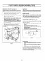
ENGUNE OIL FILTER
ILmES
MUFFLER
(See Fig. 17)
Replace the engine oil filter every season or every other oil
change if the tractor is used more than 100 hours in one
year.
o
inspect and replace corroded muffler and spark arrester (if
equipped) as it could create a fire hazard and/or damage_
Drain oil from engine crankcase (See "TO CHANGE
ENGINE OIL" through step remove drain ptug)o
SPARKPLUGS
Remove oil filter and wipe off filter adapten
o
Apply a thin coating of new engine oil to the rubber
gasket on replacement oil filter°
•
Install replacement oil filter on filter adapter. Turn oi!
filter clockwise until rubber gasket contacts the filter
adapter, then tighten filter an additional 1/2 turn°
°
Fill crankcase with new oil ( See "TO CHANGE ENGINE OIL" in this section of this manual). For approximate capacity see "PRODU CT SPECIFICATIONS" on
page 3 of this manual..
=
Start the engine and check for oil leaks.. Correct any
leaks before placing engine into full operation..
Replace spark plugs at the beginning of each mowing
season or after every 100 hours of use, whichever comes
first. Spark plug type and gap setting is shown in "PRODUCT SPECIFICATIONS" on page 3 of this manual,
IN-LINE FUEL FILTER (See Fig. 18)
Fuel filter should be replaced once each season° If fuel filter
becomes clogged, obstructing fuel flow to carburetor, replacement is required_
OIL FILTER
o
With engine coot, remove filter and plug fuel line
sections°
=
Place new fuel filter in position in fuel iine.
•
Be sure there are no fuel line leaks and clamps are
properly positioned.
°
immediately wipe up any spilled gasoline.
FUEL
ILTER
FIG. 18
CLEANING
°
Clean engine, battery, seat, finish, etc. of all foreign
matter°
°
Keep finished sudaces and wheels free of all gasoline,
oi!, etc.
o
Protect painted surfaces with automotive type wax.
FIG. 17
We do not recommend using a garden hose to clean your
unit unless the electrical system, muffler, air filter and
carburetor are covered to keep water out° Water in engine
can result in a shortened engine life.,
1-q
SERVUCE AN
=;_..........................
ADJUSTMENTS
..................
,,,,
,,.
.......
:
CAUTION: BEFORE PERFORMING ANY SERVICE OR ADJUSTMENTS:
Depress clutci_Jbrake pedal fully and set parking brake.
Place gearshift lever in "NEUTRAL" position.
O
Place attachment clutch in "DISENGAGED" position.
o
Turn ignition key "OFF" and remove key.
0
Make sure the blades and all moving parts have completely stopped.
o
Disconnect spark plug wire from spark plug and place wire where it cannot come in contact with
plug.
i,,,,,,i, i
ii
,,i
ii,ll ill
_1_ lllll
,i,,_ll:llll,,i,
•..........
i,_
ii
i
.....
TRACTOR
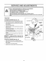
TO REMOVE
MOWER
(See Fig. 19)
LEVER
CLUTC
Mower' will be easier to remove from the right side of tractor.
=°
o
Place attachment clutch in "DISENGAGED" position°
Move attachment lift lever forward to lower mowerto its
lowest position.,
=
Roll belt off engine pulley.
=
Disconnect clutch rod from clutch lever by removing
retainer spring_
o
Disconnect anti-sway bar' from chassis bracket by
removing retainer spring.
=
Disconnect suspension arms from rear deck brackets
by removing retainer springs°
•
Disconnect front links from deck by removing retainer
springs.
=
Raise lift lever to raise suspension arms. Slide mower'
out from under tractor_
SPRING
SUSPENSION
ARMS
SPRINGS
SIDES)
RETAINER
SPRING
IMPORTANT:
1FAN ATTACHMENT OTHER THAN THE
MOWER IS TO BE MOUNTED TO THE TRACTOR, THE
R.H. AND L..H. SUSPENSION ARMS MUST BE REMOVED
FROM TRACTOR_
TO INSTALL
MOWER
ENGINE
PULLEY
ANTI*SWAY
(See Fig. 19)
BAR
RETAINER
SPRINGS
(BOTH SLOES)
FIG. 19
=
Raise attachment
lift lever' to its highest position_
•
Slide mower under tractorwith
side of tractor.
=
o
Lower lift lever to its lowest position,
Install mower in reverse order of removal instructions._
discharge guard to right
.gn
SERVtCE AND ADJUSTMENTS
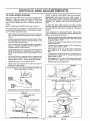
TO LEVEL
MOWER
HOUSING
FRONT-TO-BACK
ADJUSTMENT
(See Figs_ 22 and 23) _
IMPORTANT:
DECK MUST BE LEVEL SIDE-TO-SIDE,
IF
THE FOLLOWING
FRONT-TO*BACK
ADJUSTMENT
IS
NECESSARY,
BE SURE TO ADJUST BOTH FRONT LINKS
EQUALLY
SO MOWER
WILL STAY LEVEL StDE-TOSIDEo
Adjust the mower while tractor is parked on level ground or
driveway°
Make sure tires are properly inflated (See
"PRODUCT SPECiFiCATIONS"
on page 3). If tires are
over or under inflated, you wiif not properly adjust your
mower.,
SIDE-TO-SIDE
ADJUSTMENT
To obtain the best cutting results, the mower housing
should be adjusted so that the front is approximately 1/4" to
3/4 °`lower than the rear when the mower is in its highest
position.
(See Figs. 20 and 21)
You will need two (2) standard 2 x 4 short pieces of wood
to make the following adjustment° Similar blocks measuring !-1/2" thick may also be used..
o Raise mower with attachment lift control to allow two
(2) 1-1/2" thick blocks to be placed under rear edge of
mower..
•
Lower mower deck to its lowest height of cut posit!on
(See 'q'O ADJUST MOWER CUTTING HEIGHT' in
Operation section of this manual),
o
On both sides of tractor, loosen, but do not remove, the
fasteners securing the adjustable pivot brackets to
frame. Both brackets must be loose enough to move
freely..
o
°
°
Place one block directly behind the left mandrel.. Place
the remaining block under the stamped ridge on the
right rear edge of mower deck.
•
°
Check adjustment on right side of tractor. Measure distance "D" directly in front and behind the mandrel at bottom
edge of mower housing as shown..
•
•
•
o
Pull down firmly on suspension arm to remove any
slack in pivot bracket and hold while tightening rear
fastener first to secure.. Tighten remaining fasten'er.
°
Repeat procedure on other side of tractor..
Raise mower with attachment lift control and remove
blocks from under mower..
°
Before making any necessary adjustments_ check that
both front lin_s are equa!, in length_ Both I_nks should
be approximately 10-3/8.
If links are not equal in length, adjust one link to same
length as other link..
To lower front of mower loosen nut "E" on both front
links an equal number of turns..
When distance "D" is 1/4" to 3/4" lower at front than
rear, tighten nuts "F" against trunnion on both front
links.
To raise front of mower, loosen nut"F" from trunnion on
both front links. Tighten nut "E" on both front links an
equal number of turns.
When distance "D" is 1/4" to 3/4" lower at front than
rear, tighten nut "F" against trunnion on both front links,.
Recheck side-to-side adjustment.
MANDREL
PLACE TWO (2) 1-1/2" THICK BLOCKS UNDER REAR EDGE OF
DECK (Use wood 2 x 4's or equiv.)
DIRECTLY
.I
........
FIG. 22
BOTH FRONT LINKS
MOWER MUST BE IN LOWEST
MUST BE EQUAL
IN LENGTH
HEIGHT OF CUT POSITION
FIG. 20
ADJUSTABLE
BRACKET
PIVOT
NUT "E"
FASTENERS
SUSPENSION
ARM
NUT "F"
FRONT LINKS
PULL DOWN AND TIGHTEN
REAR FASTENER
TRUNNION
FIRST
21
FIG. 23
SERVICE AND ADJUSTMENTS
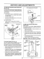
TO REPLACE
MOWER
BLADE
DRIVE
BELT
WITH PARKING BRAKE "ENGAGED"
(See Fig. 24)
The mower blade drive belt may be replaced without tools_
Park the tractor on level surface,, Engage parking brake,,
For assistance, there is a belt installation guide decal on the
mower housing,
BELT REMOVAL -
NUT "A"
o
o
Place attachment clutch in "DISENGAGED" position,,
Move attachment lift lever forward to lower mower to
its lowest position,,
°
Roll belt off engine pulley°
•
Work belt off both mandrel pulleys and idler pulleys,.
•
Pull belt away from mower.
BELT INSTALLATION
-
°"
Install new belt in reverse order of removal.
°
Make sure belt is in all pulley grooves and inside all
belt guides.
FIG. 25
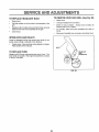
TO REPLACE
(See Fig. 26)
ENGINE PULLEY
MANDREL
PULLEY
IDLER
PULLEYS
MOTION
DRIVE
BELT
Park the tractor on leve! surfacer Engage parking brake_
For assistance, there is a belt installation guide decal on
bottom side of left footrest_
FIG. 24
BRAKE
Remove mower (See "TO REMOVE MOWER" in this
section of this manual,.)
o
Remove upper' belt keeper,
°
•
Remove belt from stationary idler and clutching idler,
Pull belt slack toward rear' of tractor. Remove belt
upwards from transaxle pulley by deflecting belt keepers.
°
Putl belt toward front of tractor and remove downwards
from around engine pulley.
°
Install new belt by reversing above procedure,
IMPORTANT:
MAKE SURE UPPER BELT KEEPER IS
POSITIONED PROPERLY BETWEEN LOCATOR TABS.
MANDREL
PULLEY
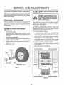
TO ADJUST
•
PULLEY
CLUTCHING
IDLER
(See Fig. 25
Your unit is equipped with an adjustable brake system
which is mounted on the right side of the transaxleo
)CATOR
TABS
If unit requires rnore than six (6) feet stopping distance at
high speed in highest gear, then brake must be adjusted.
°
Depress clutch/brake pedal and engage parking brake.
=
Measure distance between brake operating arm and
nut "A" on brake rod,,
°
If distance is other than 1-1/2", disengage parking
brake, loosen jam nut and turn nut "A" until distance
becomes 1-1/2". Retighten jam nut against nut "A"_
•
Engage parking brake and recheck distance.
°
Road test unit for proper stopping distance as stated
above, Readjust if necessary. If stopping distance is
stilt greater than six (6) feet in highest gear, further
maintenance is necessary° Contact your nearest authorized service center.
UPPER BELT
KEEPER
STATIONARY
IDLER
PULLEY
22
_1_ o_
SERVDCE A D ADJUSTMENTS
TO ADJUST
STEERING
WHEEL
ALIGNMENT
If steering wheel crossbars are not horizontal (left to right)
when wheels are positioned straight forward, remove steering wheel and reassemble per instructions in the Assembly
section of this manual..
FRONT
WHEEL
TO START ENGINE
(See Fig. 28)
WITH A WEAK
BATTERY
TOE-IN/CAMBER
The front wheel toe-in and camber are not adjustable on
your tractor,. If damage has occurred to affect the front
wheel toe-in or camber, contact your nearest authorized
service center°
TO REMOVE WHEEL
(See Fig. 27)
FOR REPAIRS
If your battery is too weak to start the engine, it should be
recharged.
If "jumper cables"
are used for emergency
starting, follow this procedure:
IMPORTANT:
YOUR UNIT IS EQUIPPED
WITH A 12
VOLT NEGATIVE
GROUNDED
SYSTEM.
THE OTHER
VEHICLE
MUST
ALSO
BE A 12 VOLT
NEGATIVE
GROUNDED
SYSTEM.
DO NOT USE YOUR TRACTOR
BATTERY TO START OTHER VEHICLES..
TO ATTACH JUMPER CABLES -
=
Block up axle securely.
•
Remove axle cover, retaining ring and washers to allow
wheel removal (rear wheel contains a square key - Do
not lose)o
o
Repair tire and reassemble..
°
On rear wheels only: align grooves in rear wheel hub
and axle.. Insert square key.
o
°
Replace washers and snap retaining ring securely in
axle groove°
TO REMOVE CABLES, REVERSE ORDER -
°
Replace axle cover_
°
o
=
o
Connect each end of the RED cable to the POSITIVE
(+) terminal of each battery, taking care not to short
against chassis,
Connect one end of the BLACK cable to the NEGATIVE (-) terminal of fully charged battery°
Connect the other end of the BLACK cable to a good
CHASSIS GROUND, away from fuel tank and battery.
BLACK cable first from chassis and then from the fully
charged battery.
RED cable last from both batteries°
POSIT1VETERMINAL
NEGATIVE
TERMINAL
WASHERS
RETAINING
RING
t
AXLE COVER
'_""' SQUARE
KEY
(REAR WHEEL ONLY)
CHASSIS
CABLES
FIG. 27
CHARGED
BATTERY
POSITIVE TERMINAL
NEGATIVE
FIG. 28
TERMINAL
SERVmCE AND ADJUSTMENTS
'
TO REPLACE
,,i,
HEADLIGHT
ui _
, ii
i,ll
.
,.................
°
Raise hood°
°
Pull bulb holder out of the hole in the backside of the
grJ{io
o
Replace bulb in holder' and push bulb holder securely
back into the hole in the backside of the grill.
Close hood.
INTERLOCKS
i
TO REMOVE
BULB
o
.
ii
...............
HOOD AND GRILL (See Fig. 29)
Raise hood,,
o
Unsnap headlight wire connector,,
o
Stand in front of tractor,, Grasp hood at sides, tint
forward and lift off of tractoL
•
To reinstall, slide hood pivot brackets
frame°
o
Reconnect headlight wire connector and close hood,.
into slots in
AND RELAYS
Loose or damaged wiring may cause your' tractor to run
poorly, stop running or prevent it from starting.
°
Check wiring. See electricaE wiring diagram in Repair
Parts section of this rnanual.
HOOD
TO REPLACE
FUSE
HEADLIGHT
WIRE
CONNECTOR
Replace with 30 amp automotive-type plug-in fuse. The
fuse holder is located in the engine compartment, directly
in front of the dash,
FIG, 29
24
SERVICE AND ADJUSTMENTS
ENGRNE
ACCELERATION
o
TO ADJUST THROTTLE
(See Fig. 30)
CONTROL
CABLE
The throttle control has been preset at the factory and
adjustment should not be necessary. Check adjustment as
described below before loosening cable° If adjustment is
necessary, proceed as follows:
o
With,engine ,no!, running, move throttle control lever
from SLOW' to CHOKE position_ Slowly move lever
from "CHOKE" to "FAST" position°
o
Check to see if hole in throttle lever and hole in speed
control bracket are atigned.
=
If holes are not aligned, loosen cable clamp screw and
align the holes by inserting a pencil or a 1/4" drill bit
through both holes..
°
Pull throttle cable up to remove slack and tighten cable
clamp screw.. Remove alighnment pencil or drill bit.
TO ADJUST
CARBURETOR
TEST -
Move throttle control lever from "SLOW"
to "FAST"
position,,
If engine hesitates
or dies, turn idle fuel
adjusting needle out (counterclockwise)
t/8 turn° Repeat test and continue to adjust, if necessary,
until
engine accelerates
smoothly_
High speed stop is factory
damage may result,
adjusted.
IMPORTANT:
NEVER
TAMPER
WITH THE ENGINE
GOVERNOR,
WHICH tS FACTORY
SET FOR PROPER
ENGINE SPEED. OVERSPEEDINGTHE
ENGtNE ABOVE
THE
FACTORY
HIGH
SPEED
SETTING
CAN BE
DANGEROUS.
IF YOU THINKTHE
ENGINE-GOVERNED
HIGH SPEED NEEDS ADJUSTING,
CONTACT
YOUR
NEAREST AUTHORIZED
SERVICE CENTER, WHICH HAS
PROPER EQUIPMENT AND EXPERIENCE
TO MAKE ANY
NECESSARY
ADJUSTMENTS°
CABLE
CLAMP
SCREW
(See Fig. 31)
The carburetor has been preset at the factory and adjustment should not be necessary,. However, minor adjustment may be required to compensate for differences in fuel,
temperature, altitude or load. If the carburetor does need
adjustment, proceed as follows:
SPEED CONTROL
BRACKET
in general, turning the adjusting needles in (clockwise)
decreases the supply of fuel to the engine giving a leaner
fuel/air mixture.. Turning the adjusting needles out (counterclockwise) increases the supply of fuel to the engine giving
a richer fuel/air mixture_
IMPORTANT:
DAMAGE
SEATS 1N CARBURETOR
TURNED IN TOO TIGHT
PRELIMINARY
o
THF
LEVER
TO THE NEEDLES AND THE
MAY RESULT IF NEEDLE IS
FIG, 30
SETTING -
Be sure you have a clean air filter and the throttle
control cable is adjusted properly (see above)_
IDLE SPEED
ADJUSTING
,
With engine off turn idle fuel adjusting needle in (clockwise) closing it finger tight and then turn out (counterclockwise) 1 turn..
FINAL SETTING °
Start engine and allow to warm for five minutes. Make
final adjustments with engine running and shift!motion
control tever in "NEUTRAL" position°
°
idle speed se_ting - With throttle control lever in "SLOW"
position, engine should idle at 1750 RPM If engine
idles too slow or fast, turn idle speed adjusting screw in
or out until correct idle is attained
o
.!d!e {u.el needle....settin__q
- With throttle control lever in
"SLOW" position, turn idle fuel adjusting needle in
(clockwise) until engine begins to die and then turn out
(counterclockwise)
approximately 1/8 to 1/4 turn to
obtain best low speed performance.
°
Recheck idle speed.
Do not .adjust
ADJUSTING
NEEDLE
Readjust if necessary.
FIG. 31
25
STORAGE
Immediately prepare your tractor for storage at the end of
the season or if the tractor wild not be used for 30 days or
ENGINE
mO re.
FUEL SYSTEM
IMPORTANT:
IT IS IMPORTANT
TO PREVENT
GUM
DEPOSITS
FROM
FORMING
tN ESSENTIAL
FUEL
SYSTEM PARTS SUCH AS CARBURETOR,
FUEL FILTER,
FUEL HOSE, OR TANK DURING
STORAGE.
ALSO,
EXPERIENCE
INDICATES
THAT ALCOHOL
BLENDED
FUELS (CALLED GASOHOL
OR USING ETHANOL
OR
METHANOL)
CAN ATTRACT MOISTURE
WHICH LEADS
TO SEPARATION
AND FORMATION
OF ACIDS DURING
STORAGE.
ACIDIC
GAS CAN DAMAGE
THE FUEL
SYSTEM OF AN ENGINE WHILE IN STORAGE.
CAUTION: Never store the tractor' with
gasoline in the tank inside a building
where fumes may reach an open flame
or spark. Allow the engine to cool
before storing in any enclosure.
TRACTOR
Remove mower from tractor for winter storage, When
mower is to be stored for a period of time, clean it thoroughly, remove all dirt, grease, leaves, etc.. Store in a
clean, dry area_
•"
Clean entire tractor (See"CLEANING"in
the Customer
Responsibilities section of this manual)_
o
Inspect and replace belts, if necessary (See belt replacement instructions in the Service and Adjustments
section of this manual)°
°
Lubricate as shown in the Customer Responsibilities
section of this manual_
°
Be sure that all nuts, bolts and screws are securely
fastened,, inspect moving parts for' damage, breakage
and wear.. Replace if necessary.
°
Touch up all rusted or chipped paint surfaces; sand
lightly before painting_
Fully charge the battery for storage_
°
After a period of time in storage, battery may require
recharging_
o
To help prevent corrosion and power leakage during
long periods of storage, battery cables should be
disconnected and battery cleaned thoroughly (see "TO
CLEAN BATTERY AND TERMINALS
in the Customer Responsibilities section of this manual).
°
Drain the fuel tank.
Q
Start the engine and let it run until the fuel lines and
carburetor are empty.
Never use engine or carburetorcleaner products in the
fuel tank or permanent damage may occur,.
Use fresh fuel next season.
NOTE: Fuel stabilizer is an acceptable alternative in
minimizing the formation of fuel gum deposits during storage. Add stabilizer to gasoline in fuel tank or storage
container.. Always follow the mix ratio found on stabilizer
container. Run engine at least 10 minutes after adding
stabilizer to allow the stabilizer to reach the carburetor. Do
not drain the gas tank and carburetor if using fuel stabilizer.
ENGINE
OIL
Drain oil (with engine warm) and replace with clean engine
oil. (See "ENGINE" in the Customer Responsibilities
section of this manuat)_.
BATTERY
o
°
CYLINDERS
After cleaning, leave cables disconnected and place
cables where they cannot come in contact with battery
terminals.
°
Remove spark plug(s),
°
Pour' one ounce of oil through spark plug hole(s) into
cylinder(s)o
=
Turn ignition key to"START" position for a few seconds
to distribute oil.
°
Replace with new spark plug(s).
OTHER
=
Be sure battery drain tube is securely attached_
=
Do not store gasoline from one season to another,
°
tf battery is removed from tractor' for storage, do not
store battery directly on concrete or damp surfaces.
.
Replace your gasoline can if your can starts to rust.
Rust and/or dirt in your gasoline will cause problems.
=
If possible, store your tractor indoors and cover it to
give protection from dust and dirt.,
.
Cover your tractor with a suitable protective cover that
does not retain moisture. Do not use plastic. Plastic
cannot breathe which allows condensation to form and
will cause your tractor' to rust.
IMPORTANT: NEVER COVER TRACTOR WHILE ENGINE
AND EXHAUST AREAS ARE STILL WARM.
26
TROU
PROBLEM
Will not start
LESHOOTING
CORRECTION
CAUSE
1
Out of fuel
2,
3.
4,,
5,
6.
7
Engine not "CHOKED"
Engine flooded
Bad spark plug
Dirty air filter
Dirty fuel filter
Water in fuel
8,
9..
Loose or damaged wiring.
Carburetor out of adjustment.
t0
POUNTS
properly
Engine valves out of adjustment.
t.
2,
3.
4,
5.
6
7
8,
9_
10,
Fill fuel tank
See "TO START ENGINE" in Operation section,
Wait several minutes before attempting to start,
Replace spark plug,
Clean/replace air filter,
Replace fuel filter,
Drain fuel tank and carburetor, refill tank with fresh
gasoline and replace fuel filter,
Check all wiring,
Contact an authorized service center/department,
Contact an authorized service center/department
I
2,
3
4
5,
Cleanlreplace air filter
Replace spark plug
Recharge or replace battery_
Replace fuel filter
Drain fuel tank and refill with fresh gasoline.
Engine valves out of adjustmenL
&
7,
8
Checkall wiring
Contact an authorized service center/department
Contact an authorized service center/department
1,
2
3
4,
5.
&
7,
8
9
Clutch/brake pedal not depressed
Attachment clutchis engaged,
Weaker dead battery
Blown fuse.
Corroded battery terminals
Looseor damaged wiring,
Fault,} ignition switch.
Fault,/solenoid or starter
Faulty operator presence switch(es),
1_
2,
3
4
5
6
7.
8,
9,
Depress clutch/brake pedal
Disengage attachment clutch
Recharge or replace battery.
Replace fuse,
Clean battery terminals
Check all wiring
Check/replace ignition switch.
Check/replace solenoid or starter,
Contact an authorized service centeddepartment,
Engine clicks but will not
start
I,
2,.
3
4
Weaker dead battery,
Corroded battery terminals,
Looseor damaged wiring,
Faulty solenoid or starter.
1
2,
3,,
4,
Recharge or replace battery,
Clean battery terminals,
Check all wiring,
Check/replace solenoid or starter,
Loss of power
1,
2.
3,
4
5
Cutting too much grass!too fast.
Throttle in "CHOKE" position
Build-up of grass, leaves and trash under mower
Dirty air filter
Low oil ]eve!ldirty oil.,
t,
2.
3,
Set in "Higher Cut" position/reduce speed,
Adjust throttle control
Clean underside of mower housing
6.
7,,
8.
9
Faulty spark plug
Dirty fuel filter
Stale or dirty fuel
Water in fuel
4
5,
6
7
8.,
9.
Clean/replace air filter,,
Check oil levellchange oil
Clean and regap or change spark plug,,
Replace fuel filter,
Drain fuel tank and refill with fresh gasoline
Drain fuel tank and carburetor, refill tank with fresh
Hard to start
1
2
3
4.
5,
6,
7
Dirty air filter
Bad spark plug
Weak or dead battery.
Dirty fuel filter_,
Stale or dirty fuel.
Loose or damaged wiring.
Carburetor out of adjustment.
8
Engine will not turn over
................
,,,,,,,
t0,
11.
t2
13,
14.
15,
Excessive vibration
t
2
3.
Spark plug wire loose,,
Dirty engine air screen/fins
Dirty/clogged muffler
Loose or damaged wiring
Carburetor out of adjustment
Engine valves out of adjustment,
Worn, bent or loose blade
Bent blade mandrel
Loose/damaged part(s)
10,
11
12
t3,
t4,.
15,
1
2,
3
gasoline and replace fuel filter.,
Connect and tighten spark plug wire,
Clean engine air screen/f_ns.,
Clean/replace muffler,
Check all wiring.
Contact an authorized service center/department..
Contact an authorized service center/department
Replace blade Tighten blade bolt,
Replace blade mandrel.,
Tighten loose part(s) Replace damaged parts
TIROUBLESHOOT
PROBLEM
CAUSE
G POINTS
CORRECTION
Engine continues to run
when operator leaves seat
with attachment clutch
engaged
t
Faulty operator-safety
Poor cut - uneven
1.,
2,
Worn, bent or loose blade
Mower deck not level
3.
4,
Buildup of grass, leaves, and trash under mower
Bent blade mandrel.
5.
Clogged mower deck vent holes from buildup of
grass, leaves, and trash around mandrels
Mower blades will not
t
Obstruction
rotate
2
3
4
Worn/damaged mower drive belt
Frozen idler pulley
Frozen blade mandrel,.
Poor grass discharge
t.
2..
3,.
4..
Engine speed too slow
Travel speed too fast
Wet grass
Mower deck not levei
I.
2.
3.
4
Place throttle control in "FAST" position
Shift to slower speed.
Allow grass to dry before mowing
Level mower deck.
5.
6.
Low/uneven tire air pressure
Worn, bent or loose blade
7
8.
Buildup of grass, leaves and trash under mower
Mower drive belt worn.
9.
10
1t
Blades improperly installed
Improper biadesused
Clogged mower deck vent holes from buitdup of
grass, leaves, and trash around mandrels
i,
,
i r
presence control system
1
Check wiring, switches and connections
if not
corrected, contact an authorized service center/
department
1
2.
3.
4.
5.
Replace blade Tighten blade bolt
Level mower deck..
Clean underside of mower housing
Replace blade mandrel
Clean around mandrels to open vent holes
!_.
Remove obstruction
2
3..
4.
Replace mower drive belt
Replace idler pulley
Replace blade mandreI
I
Headlight(s) not working
(if so equipped)
Battery will not charge
Engine "backfires"
when turning engine
"OFF"
in clutch mechanism
5
6
7
8
9
10
11
Check tires for proper air pressure,.
Replace/sharpen blade, Tighten blade bolt
Clean underside of mower' housing
Replace mower drive belt
Reinstall blades sharp edge down
Replace with blades listed in this manual
Clean around mandrels to open vent holes..
1
Switch is "OFF".
1
Turn switch "ON",.
2
3
4.
5.
Bulb(s) burned out.
FauIty light switch
Loose or damaged wiring,.
Blown fuse
2
3
4
5
Replace bulb(s)
Check/replace light swilch,.
Check wiring and connections
ReplAce fuse..
1
2,
Bad battery cell(s),
Poor cable connections
3,
4,
Faulty regulator (if so equipped),
Faulty alternator
1
2
3
4
Replace battery
Check/clean all connections.
Replace regulator.
Replace alternato[..
!,
Engine throttle control not set at "SLOW"
position for 30 seconds before stopping engine
1
Move throttle control to "SLOW" position and allow
to idle for 30 seconds before stopping engine.
14 HP 42" TRACTOR
- - MODEL NUMBER
917.254850
SCHEMATIC
o111o
!11
l
BATTERY
RED
FUSE 30 AMP,
I
STARTER
WHIT
BLACK
CLUTCH / BRAKE
(PEDAL UP)
t
-22_
SEAT SWITCH
'
-
(NOT OCCUPIED)
----4----
'
!
BLACK
ATT'MENT CLUTCH
(CLUTCH OFF)
GROUNDING
CONNECTOR
'1
BLACK
,GNmON_
UNIT
SPARK
@
PLUG
BLUE
28 VOLTS AC MIN. @ 3800 RPM
(CHARGING SYSTEM DISCONNECTED)
CHARGING SYSTEM OUTPUT
3 AMP DO @ 3600 RPM
RED
DIODE
UGHTING
t
5 AMP AC @ 3600 RPM
,_
14 VOLTS
ORANGE
t ALTERNATOR
_
I
|
t
i
AO MIN
.........
_1
@ 3600 RPM (LIGHTS OFF)
BROWN
HEADLIGHT
SWITCH (OFF)
IGNITION SWITCH
POSITION
CIRCUIT
OFF
M+G
ON
B+L
START
8+S+L
NON-REMOVABLE
CONNECTIONS
WIRING INSULATED CLIPS
NOTE; IF WIRING INSULATED
CLIPS WERE REMOVED FOR
SERVICING OF UNIT, THEY
SHOULD BE REPLACED TO
PROPERLY SECLIRE YOUR
WIRING
(_
REMOVABLE
CONNECTIONS
_q
NOTE
YOUR TRACTOR IS EQUIPPED WITH
A SPECIAL ALTERNATOR SYSTEM.
/" 7
THE LIGHTS ARE NOT CONNECTED
TO THE BATTERY, BUT HAVE THEIR
OWN ELECTRICAL SOURCE.
BECAUSE OF THIS, THE BRIGHTNESS
OF THE LIGHTS WILL CHANGE WITH
ENGINE SPEED. AT IDLE THE LIGHTS
WILL DIM. AS THE ENGINE IS
SPEEDED UP, THE LIGHTS WILL
BECOME THEIR BRIGHTEST,
REPAURPARTS
14 HP 42" TRACTOR
- - MODEL NUMBER
917.254850
ELECTRICAL
33
32
4
36
19
16
28
7
/
!
\
6
/
\
/
C_
!
J
26
/
/
"
27
_
I
I
8
I
I
I
t
I
30
\
REPARR PARTS
14 HP 42" TRACTOR
- - MODEL NUMBER
917.254850
ELECTRICAL
KEY PART
NO. NO,
DESCRIPTION
1
2
3
4
5
6
7
8
9
10
11
12
13
15
t6
17
19
20
21
22
23
24
25
26
27
28
29
3O
3t
32
33
34
35
36
37
39
Battery 12 Volt 25 Amp
Switch Ignition
Nut Ignition
Harness Ign KOH Fender HI
Cable Ground 6ga 12"black
Cable Battery 6 Ga 43 red
Cable Battery 6ga 11 "red
Case Battery Hng Mech W/lid
Clamp Hose Olive
Solenoid
Lockwasher
Nut Jam Hex 1/4_20 Unc
Bolt Fin Hex 1/4-20uncx1/2 Gr5
Nut
Cover Terminal Red
Switch intlk Clutch Red 4 Term
Switch lntlk Clutch Red 2 Term
Screw
Switch Plunger Nc Gray
Caps Battery 20/25/30 Amp
Bolt Hex Hd 1/4-20unc X 3/4
Wasi_er
Washer
Nut
Key lgn Molded Craftsman
Fuse 30 Amp Auto Green
Tube Plastic 12"
Cover Sw Key BIk 1 25 Text Sit
Switch Light BIk BIk Red
Harness Socket Light
Bulb Light #1141
Bracket Switch Clutch
Screw
Bracket Switch Interlock
Screw
Washer Lock int. Tooth 1/4
121265X
102972X
124211X
138088
4207J
132202
4799J
129965
109596X
138406
STD551125
73350400
7t110408
STD541425
131563
109553X
104445X
STD601005
121305X
121264X
74760412
STD551025
STD551125
STD541025
109310X
108824X
109238X
123620X
t10712X
136850
4152J
108236X
STD601005
130890
STD601005
11150400
NOTE:
All component dimensions given in UoSoinches
1 inch = 25.4 mm
31
REPAmRPARTS
14 HP 42" TRACTOR
CHASSIS
A
B
- - MODEL NUMBER
917.254850
AND ENCLOSURES
C
D
E
F
G
i
J
K
L
M
P
Q
52
28
10
21
11
17
37
3O
13
33
37
G
3o
REPAIlR PARTS
14 HP 42" TRACTOR
CHASSIS
-- MODEL
NUMBER
917.254850
AND ENCLOSURES
KEY
NO.
1
2
3
6
7
8
9
10
11
12
13
!4
15
16
17
18
19
20
21
22
24
25
26
27
28
29
30
31
32
33
34
35
36
37
38
39
4O
5O
51
52
53
54
PART
NO,
t35034
130805
17490612
t26595X014
17490608
126471X
13741 tX015
5479J
122795X
t21794X
126276X
17490608
74180512
STD541431
13'1445X459
126938X
STD512505
STD551 t25
122933X
124479X
STD523707
19131312
STD541437
17490608
126741X
124029X
126599X459
1366t9
17490612
105465X459
105464X459
STD533707
STD541437
105466X
134774
134775
STD533707
STD541437
19131216
'134014
72140608
747606'14
DESCRIPTION
Chassis Weldment
Drawbar 11 Ga 46 5"wheel Base
Screw Thdrol 3/8-16x3/4 Ty-tt
Saddle Silkscreened
Screw Thdrol 3/8-16xl/2 Ty-tt
Clip Insulated 406 Mtg Hole
Dash Silkscreened Eng
Plug Button Blk 359 Dia
Panel Pnt Dash Lh
Cover Access Black Square
Panel Dash Rh Weldment
Screw Thdrol 3/8-16xl/2 Ty-tt
Screw Mach Trhd 5/16-18uncx3/4
Nut
Hood Asm Pnt Weld Dover S_pe
Bumper Hood
Screw
Washer
Rivet Ratchet Nylon
Washer Nylon Blk 28x 75x 19
Bolt
Washer '13/32 X 13/16 X 12 Ga
Nut
Screw Thdrol 3/8-16xl/2 Ty-tt
Grille Black
Lens Headlight Bar Clear
Fender Pnt
Bracket Pnt Fender
Screw Thdrol 3/8-16x3/4 Ty-tt
Footrest Pnt Lh
Footrest Pnt Rh (dover Gray)
Bolt
Nut
Pad Footrest Rbr Sq Craftsman
Bracket, Assembly, Pivot L°Ho
Bracket, Assembly, Pivot R,H.
Bolt Carriage 3/8o16 x 3/4
Locknut Hex wiVVsh 3/8-16 Unc
Washer 13/32 x 3/4 x 16 Ga,
Plug Dome Black
Bolt, Carriage 3/8_16 UNC x 1
Bolt, Hex 3/8-16 x 7/8
NOTE: All component dimensions given in U_S.,inches
1 inch = 25.4 mm
33
REPAUR PARTS
DRIVE
14 HP 42" TRACTOR
- - MODEL
NUMBER
917,254850
58
21
87
18
17
50
18
62
35
36
34
53
22
_4
26
REPAUR PARTS
14 HP 42" TRACTOR
- - MODEL NUMBER
917.254850
DRIVE
KEY
NO.
PART
NO.
1
2
3
4
5
6
8
10
11
12
13
14
17
18
19
20
21
22
23
24
25
26
27
28
29
30
3t
32
33
34
35
36
37
38
39
40
41
42
43
44
45
46
47
48
49
137363
110422X
123666X
12000028
12t520X
17490512
127270
76020416
105701X
19151216
71040412
STD551125
121520X
STD523707
STD541437
174905'12
t06933X
130804
STD541437
STD541237
106888X
STD551037
STD561210
128904
124236X
130807
127275X
STD523107
STD541431
122424X
120183X
STD551062
STD571810
123674X
STD523727
4470J
t09070X
19131312
STD541437
105706X
110812X
12000039
127783
123789X
123205X
KEY
NO.
DESCRIPTION
Transaxie 6 sp,, Dana 4360-48
Spring Extension Brake
PulleyTransaxle
18 tires
Ring Retainer # 5100-62
Strap Torque
Screw Thdrol 5/16-18 X 3/4 Tyt
LeverShift Weld Pnt
Pin Cotter
Washer Shift Plate
Washer '15/32 x 3/4 x 16 Ga,,
Bolt Fin Hex 1/4-28unfx3!4 Gr8
Washer
Strap Torque
Bolt
Nut
Screw Thdrol 3/8-16x3/4 Ty-tt
Knob Rd i/2-13 Plstc Thds BIk
Rod, Brake
Locknut
Nut
Spring Rod Brake 2 00 Zinc
Washer
Pin
Rod Brake Parking Lt
Cap Parking Brake Red
Bracket Mtg Transaxle
Keeper Belt Lh Lt 14 Ga
Bolt
Nut
Shaft Asm Pedal Foot ! 930
Bearing Nylon BIk 629 Id
Washer
Roll Pin
Pulley Idler Flat
Bolt
Spacer Split 395 X 59 Bzp
Keeper Belt Retainer
Washer !3/32 X t3/I6 X !2 Ga
Nut
Bearing, Nylon
Washer Hardened
Ring Klip #t5304-50
Pulley Idler V Groove Plastic
BellcrankAsm
Retainer Belt Style Spring
50
5t
52
53
54
55
56
57
58
59
60
61
62
63
64
65
66
67
68
69
70
71
72
73
74
75
76
77
78
80
81
82
83
84
85
86
87
88
89
90
91
93
95
PART
NO.
STD523715
STD541437
STD551037
105710X
STD561210
105709X
STD561210
138255
127274X
136715
19131312
17490612
8883R
140186
M747810100
STD551143
129921
STD523710
19131312
STD541437
134683
STD523710
19132012
STD541437
109502X
121749X
STD58t075
123583X
121748X
131488
136932
123782X
19171216
132182
73530400
71208
19212016
12000008
131636
124346X
74760540
STD541431
17490612
DESCRIPTION
Bolt
Nut
Washer
Link Clutch 7 66
Pin
Spring Return Clutch 6 75
Pin
V-belt Ground Drive
Keeper Belt Rh Lt Pntizinc 16g
Keeper Belt Chassis Span Ctr
Washer13/32 X 13/16 X 12 Ga
Screw Thdrol 3/8-16x3/4 Ty-tt
Cover Pedal Blk Round
Pulley Engine
Bolt Hex
Washer
Keeper Belt Engine Lh Lt
Bolt
Washer 13/32 X 13/16 X 12 Ga
Nut
Guide Belt Dr Mower Rh
Bolt
Washer 13/32 X 1-1/4 X 12 Ga
Nut
Spacer Split 80 X 94
Washer 25/32 X '1 t/4 X 16 Ga
E Ring
Key Square 2 0 X 1845/t865
Washer 25/32 X 1 5/8 X 16ga
Arm, Shift
Shaft Asm. Cross Stretch
Spring Torsion
Washer 17/32 x 3/4 x 16 Gao
Rod Tie ShfL Adjo Ball
Nut, Nylock
Bushing Pivot
Washer
Ring, E
Console Shift 6sp W/ign Lt
Nut Self-thd Wsh-hd 1/4 Zinc
Bolt Fin Hex 5/16-18 x 2-1t2
Nut
Screw Thdroi 3/8 - 16 x 3/4
NOTE: All component dimensions
1 inch = 25°4 mm
35
given in U.S. inches
REPAMRPARTS
14 HP 42" TRACTOR
STEERING
-- MODEL
NUMBER
917.254850
ASSEMBLY
46
36
2
7
3
33
/
16
32
43
12
/
. 25
26
/
10
.'tR
35
/
I
\
/
t
!
/
443
45
IREPAIR PARTS
14 HP 42" TRACTOR
STEERING
- - MODEL
NUMBER
ASSEMBLY
KEY
NO.
PART
NO.
1
2
3
4
5
6
7
8
9
10
11
12
13
14
15
16
17
18
19
20
21
22
23
24
25
26
27
28
29
30
31
32
33
34
35
36
37
38
39
40
41
42
43
44
45
46
47
12t472X
133988
135227
135228
6266H
121748X
19272016
12000029
3366R
130468
STD551137
736'106O0
110438X
74O11056
739010O0
132624
132614
57O79
124035X
126684X
STD551125
71O70410
127501
1098t6X
124036X
12000029
136874
6266H
17490612
STD551137
73610600
130465
126847X
19131416
STD561210
132196
STD611005
126805X
19133808
STD541537
104820X
124417X
t21749X
121748X
12OO0029
121232X
6855M
NOTE:
DESCRIPTION
Wheel Steering
Axle Asm Front
Spindle Asm Lh
Spindle Asm Rh
Bearing Race Thrust Harden
Washer 25/32 X 1 5/8 X 16ga
Washer 27/32 X 1 1/4 X 16 Ga
Ring Klip #t5304-75
Bearing Col Strg BIk
Link Drag Sol Ball Jt 20 064
Lockwasher
Nut Fin Hex 3/8-24 Unf
Spacer Bearing Axle Front
Bolt Hex 5/8-11 Uric X 3-1/2
Nut Lock Flange 5/8-11
Pin Axle 5/8 X 1 55/t 54 Lg
Shaft Asm Strg 5/8 X 15 19 Lt
Washer Thrust 515x 750x 033
Support Shaft
Washer Shim 1/4 X 5/8 X 062
Washer
Screw Hex Socket 1/4-20 X 5/8
Shaft Asm Pittman
Nyliner Snap In
Bracket Steedng
Ring Klip #t5304-75
Gear Sector
Bearing Race Thrust Harden
Screw Thdrol 3/8-16x3/4 Ty-tt
Lockwasher
Nut Fin Hex 3/8-24 Unf
Rod Tie Wire Form 19 75 Mech
Bushing Link Drag Blk
Washer 13/32 X 7/8 X 16ga
Pin
Bushing Strg 5/8 Id Dash
Screw
Insert Cap Strg Wh Au Gen BIk
Washer 13/32 X 2-3/8 X 8 Ga
Gripco Nut
Adaptor Wheel Strg 640/635id
Boot Shaft Steering
Washer 25/32 X 1 1/4 X 16 Ga
Washer 25/32 X t 5/8 X 16ga
Ring Klip #t5304-75
Cap Spindte Fr Top BIk
Fitting Grease
All component dimensions given in U,S, inches
1 inch = 25.,4 rnm
"J7
917.254850
REPAIR PARTS
14 HP 42" TRACTOR
- - MODEL
NUMBER
917.254850
SEAT ASSEMBLY
\
14
10
12
KEY
NO.
PART
NO.
1
2
3
4
5
6
7
8
9
10
!1
12
13
14
127438X
! 26656X
STD523707
19131610
2751 R
STD541437
124181X
17490616
19131614
131451
12125! X
121246X
121248X
7205O411
DESCRIPTION
Seat V-450 BIk/red Craftsman
Bracket Pnt Pivot Seat (btk)
Bolt
Washer 13/32 X 1 X 10 Ga
Clip Line Fuel 13/32 Mtg Hole
Nut
Spring Seat Cprsn 2 250 Blk Zi
Screw Thdrol 3/8-16 X 1 Ty-tt
Washer 13/32 X 1 X 14 Ga
Pan Pnt Seat (blk)
Strip Foam Gray Or Black
Bracket Pnt Mounting Switch
Bushing Snap Blk Ny( 50 Id
Bolt Rdhd Sht Nk 1/4-20xl-3/8
KEY
NO.
PART
NO.
15
t6
17
18
19
20
21
22
23
24
25
26
13430O
t21250X
123976X
STD511005
73951000
4171R
105529X
STD541431
74780814
19171912
127018X
STD551150
NOTE:
.qR
DESCRIPTION
Spacer Split 28 X 88 Zinc
Spring Gprsn 1 27 BIk Pnt
Nut Lock 1/4 Lge Fig Gr 5 Zinc
Screw
Nut Keps #10-32 Unf
Clip Insulated 11/32 Mtg Hole
Bolt Shoulder' 5/16-18 Unc Blkz
Nut
Bolt Fin Hex 1/2-13 X 7/8 Gr 5
Washer 17/32 X 1-3/16 X 12 Ga
Bolt Shoulder 5/16-t8 X 62
Lockwasher
All component dimensions
1 inch = 25.4 mm
given in U+S inches
REPAUR PARTS
14 HP 42" TRACTOR
- - MODEL
NUMBER
917.254850
DECALS
9
13
18
6
3
7
19
5
11
7
\
4
8
12
13
14
17
KEY
NO.
1
3
4
5
6
7
8
9
10
11
PART
NO.
136794
138137
128382
132674
133644
133204
133178
128314
137537
4900J
KEY
NO.
DESCRIPTION
Decal
Decal
Decal
Decal
Decal
Decal
Decal
Decal
Decal
Decal
Instruction Operat Eng
Hood Rh Craftsman Lt4000
Hood Lh Craftsman Lt4000
Grille Lt4000 Craft Usa
Maint Cust Sears Domesti
Panel Side
Mower 3 In One Conv
Fender Craftsman White
Caution English/Spanish
Clutchtbrake English
12
t3
14
17
I8
19
---_
PART
NO.
109199X
131473
136832
133179
132266
131265
138311
137891
137892
DESCRIPTION
Decal V-belt Dr Sch Tractor E
Decal Chassis 6sp 42"
Decal V-belt Schematic 42"eng
Decal Mower Qc System
Decal Insr Wh Strg Usa
Decal, Lightbox Grill
Decal, Handle Lift (Lift Hand_e)
Manual Owners (English)
Manual Owners (Spanish)
NOTE: All component dimensions given in L£S.. inches
1 inch = 25..4 mm
WHEELS
& TIRES
i,8
10
KEY
NO.
PART
NO.
1
2
3
4
5
6
7
8
9
10
11
59192
65139
106222X
59904
I06732X311
278H
9040H
106108X311
106268X
7152J
104757X
NOT"
39
DESCRIPTION
Cap Valve Tire
Stem Valve
Tire F Ts 15 X 6 0 - 6 Service
Tube Front (Service Item Only)
Rim Asm 6"front White Service
Fitting Grease (Front Wheel Only)
Bearing Flange (Front Wheel Only)
Rim Asm 8"rear White Service
Tire R Ts 18x9 5-8 C Service
Tube Rear (Service Item Only)
Cap Axle BIk 1 50 X ! 00
&ll component dimensions given in U.S_ inches
1 inch = 25°4 mm
REIPAHRPARTS
14 HP 42" "TRACTOR - .. MODEL
NUM_R
917.254850
ENGINE
27
3
B
D
13
25
15
38
34
29
!
Spark Arrester
....
..i....
i
i
..................
i
30
B
D
E
F
G
H
I
22
18
20
19
4i3
21
REPAUR PARTS
14 HP 42" TRACTOR
-- MODEL NUMBER
917.254850
ENGINE
KEY
NOo
1
2
3
1t
12
13
14
15
16
I7
18
19
20
21
22
23
24
25
26
27
29
3O
31
32
33
34
35
36
37
38
PART
NO.
132760
17720410
13751O
STD551131
STD523105
137350
13280328
13200300
STD551237
M740t08025
136718
105839X
105838X
STD551025
123650X
128953
STD601005
126842X
17030808
105037X
137180
127057X
109202X
123549X
123487X
124028X
17490412
19091416
101335K
---
NOTE:
DESCRIPTION
Controt Throt Ch Rh BIk Pdl 22 60
Screw Hex Thd Cut 1/4-20x5/8 T
Engine, Model No. LT14S,
Type No. PS1452
Washer Lock HW Hlcl Spr 5/16
Bolt Hexhd 5/16_18xl/2
Muffler Lt Koh
Nipple Pipe 3/8 Npt X 3-1/2"
Elbow Std 90 Degree 3/8-18 Npt
Washer Lock Ext Tooth 3/8
Bolt Hex
Shield Pnt Heat
Receptacle 1/4 Turn Dacrotized
Retainer 1/4 Turn 365odx 222id
Washer 9/32 X 5/8 X 16 Ga
Stud 1/4 Turn (reptaces 105751
Shield Pnt Heat Browning Grass
Screw Tap Hex #10-24unc X 1/2
Shield Pnt Heat Hood Lt
Screw Spidertoc Hexhd#8xl!2 Ab
Strip Foam 18"
Arrestor Spark
Strap Hood
Tank Fuel 1 25 Fr
Cap Asm Fuel W/sym Vented
Clamp Hose BIk
Bushing Snap Nyl Blk Fuel Line
Screw Hexwsh Thdrol 1/4-20x3/4
Washer 9/32 X 7/8 X 16ga
Line Fuel 9 50"
Plug Oil Drain (Order From Engine
Manufacturer)
All component dimensions
1 inch = 25°4 mm
41
given in U_S. inches.
REPABFI PARTS
14 PiP 42" TRACTOR
42" MOWER
- - MODEL
NUMBER
917.254850
DECK
65
66
68
4O
76
77
78 79
19
21
84
22
80
81
_86
16
28
27
29
88
8O
AO
REPASR PARTS
!4 HP 42" TRACTOR
42" MowER
KEY
NO.
1
2
PART
NO.
138024
72140506
3
4
4A
5
6
7
8
9
10
1t
t2
13
138017
138440
132827
4939M
130832
73800500
850857
100306O0
129962
134149
129895
137645
14
15
t6
17
18
19
2O
21
22
23
24
25
26
27
28
29
30
31
32
33
34
35
36
37
38
39
4O
41
42
43
44
128774
110485X
136929
72110618
72140505
7380O500
136888
7368O500
134753
131267
105304X
123713X
110452X
130968
19111016
131491
78158
129963
129861
137266
7211O614
133835
131494
19131612
133502
133503
73680600
133551
76020312
133504
134236
- - MODEL NUMBER
917.254850
DECK
KEY
NO.
DESCRIPTION
Mower Housing
Bolt Rdhd Sqnk
5/16-18 Unc x 3/4
Bracket Asm Fr. Sway Bar
Bracket Asmo Deck Sway Bar
Bolt, Shoulder
Retainer Spring
Arm Rear Suspension
Locknut Hex W/ins. 5/16-18 Unc
Bolt 3/8-24 x 1 25 Gr8 Patched
Washer Lock Hvy 3/8 Unplated
Washer Hard Blade Mower Vented
Blade Mulching 42"
Bearing Ball #6204 (mandrel)
Shaft Asm W!tower Bearing
(Inc. Key #12)
Housing Mandrel Vented (machd)
Bearing Ball Mandrel
Stripper Mower Vented
Bolt Rdhd Sqnk 3/8-16 x 2-1/4
Bolt, Carriage 5/16-t8 x 518
Locknut Hex W/Ins. 5/16-18
Baffle Vortex
Nut Crown Lock 5/16-18
Stiffner Bracket 42" deck
Bracket Deflector Mower 42"
Cap Sleeve 80 x 112 Btk Mower
Spring Torsion Deflector 2 52
Nut Push Phos & Oil
Shield Deflector Mower 42" BIk
Wsher t 1/32 x 5/8 x 16 Ga
Rod Hinge 426 75 Wtg
Bolt 5/I6-18 x 1 25 T/t
Washer Spacer Mower Vented
Pulley Mandrel 42"
Nut 9/16 top Lock Ffng Oil Dip
Bolt Rdhd 3/8-16 Unc x t-3/4 Gr5
Fastner Christmas Tree
Pulley Idler Fiat 3 060
Washer 13/32 x I x 12 Ga
Spacer Arm Idler Upper Hdn 42"
Stiffner Arm Idler Upper 42 ....
Nut Crownlock 3/8-16 Unc
Rod Pivot W!nibs
Pin Cotter 3/32 x 3/4 Cad
Rod Clutch Secondary W/nibs
Guard Mandrel Lh Black
PART
NO.
45
46
4497H
17720410
47
48
49
50
51
52
53
54
55
56
57
58
59
60
6t
62
63
64
65
66
67
68
74
75
76
77
78
79
80
81
83
84
85
86
87
88
--
131335
133944
133940
131340
69180
105529X
131845
133943
133844
122052X
127498
128759
133573
134666
13187O
127847
121748X
12000029
128903
127845
106932X
130969
136420
71161O10
19061216
100710O0
130758
2029J
133814
133957
7393060O
7476O512
73510500
72'110504
132263
132262
137646
138357
NOTE:
43
DESCRIPTION
Spring Retainer 1 Zinc/cad
Screw Hex Thd Cut
1/4-20 x 5/8 T
Spring Extension
Washer Hardened Smaller
Roller Asm Cam Follower 42" deck
Bolt Shldr 10-24 Zinc Gr5 42"
Nut Lock #10-24 Unc
Bolt Shoulder 5/16-18 Unc Bikz
Arm Asm Pad Brake
Washer Hardened
Arm Idler 42" mower Lt/yt
Spacer Retainer Pm Mower
Bushing 747 Od x 794 Lg Brass
Spring Clutch Mower 2 750 Zinc
Arm Asm Clutch Primary
Rod Clutch Primary
Spring Return
Arm Clutch Secondary
Washer 25/32 x I-5/8 x 16 Ga
Ring Klip #t5304-75
Bolt Shoulder 3/8-16 Unc I 44
Keeper Spring 4 000
Knob Rd 3/8-16 Plstc Thds BIk
V-Belt Mower 42" 92 40
Cover Mulching 42" Blk
Screw
Washer #10
Washer Lock #10
Latch Asm Bagger
Nut Weld
Bolt Shoulder
Wheel Gage Donut
Nut Locking 3/8-16 Unc BIk
Bolt Hex 5/16-18 x 3/4
Nut Keps 5/16-18
Bolt Carriage 5/16-18 x 1/2
Bracket Gage Wheel LH 42" Deck
Bracket Gage Wheel RH 42" Deck
Mandrel Asm Service (Includes Key
Nos. 8-t0, 12-15, 31 and 33)
Deck Serv 42" Mech Vent
(Std. Deck -Order Separately
mulching and gauge wheel
components key nos 74-88)
All component dimensions
1 inch = 25.4 mm
given in US. inches
REPAIR PARTS
14 HP 42" TRACTOR
- - MODEL
NUr_BER
917.254850
LiFT
28
27
26
25 24
23
22
4 5
21
6
13
2O
44
REPAHR PARTS
'14 HP 42" TRACTOR
-- MODEL NUMBER
917.254850
LiFT
KEY
NO.
PART
NO.
!
2
3
4
5
6
7
8
10
11
12
13
14
15
16
17
18
20
19
21
22
23
24
25
26
27
28
29
3O
136973
122507X
105767X
STD581062
19211621
120183X
125631X
122365X
122512X
134619
135388
STD624008
'135563
127218
7335080O
13017'1
STD541450
3146R
130832
19151216
12000037
110807X
STD551037
2876H
STD560907
126971X
STD541237
138057
110810X
DESCRIPTION
Wire Asm Inner W/Plunger
Shaft Asm, Lift
Pin Groove
E Ring #5133-62
Washer 21/32 x I x 21 Ga.
Bearing Nylong
Grip Handle Fluted
Button Plunger Read
Spring Cprsn
Link Lift Lh Fixed Length
Link Lift Rh Fixed Length
Retainer Spring
Pin Roll Sit 5/16 x 1.25
Link Front
Nut Jam Hex t/2-13 Unc
Trunnion Blk Zinc
Nut LockWiWsh
1/2-13 Unc
Retainer Spring
Arm Suspension Rear
Washer 15/32 x 3/4 x 16 Ga..
Ring Klip #T5304-37
Nut Special
Washer 13/32 x 5/8 x 16 Gao
Spring 2-1/8"
Pin Cotter 3/32 x t/2
Rod Adj. Lift
Nut Hex Jam 3/8-16 Unc
Knob Inf. 3/8-16 Uric BIk w/Sym
Trunnion Dp Stop Dbl Thds Pit
45
REPAIR PARTS
14 HP 42" TRACTOR
DANA TRANSAXLE
- MODEL
NUMBER
-- MODEL NUME_ER 917.254850
4360-48
22
19
24
29
30
26
27
35
56
12
38
ti =
39
37
I
19
52
4O
53
4
5
4t
42
45"
16
17
54
44
45
55
46
47
56
48
57
49
59
50
58
51
55
6O
62
63
59
65
///6/4
72
6869
12`3
46
19
REPA6R PARTS
14 HP 42" TRACTOR
DANA TRANSAXLE
KEY PART
NO. NO.
1
2
138248
2274J
3
4
5
6
7
8
9
10
11
12
13
14
15
16
17
18
19
20
2t
22
23
24
25
26
27
28
29
30
31
32
33
34
35
36
37
38
134400
105904X
105905X
138235
134399
134791
I38241
2267J
134793
t38240
120415X
2257J
'138234
110078X
105909X
105910X
105911X
138242
138246
138236
73810500
138243
2244J
t05916X
120470X
110070X
108977X
109254X
120405X
108980X
120406X
134796
105925X
2232J
I08978X
110079X
39
4O
124639X
120472X
- MODEL
NUMBER
-- MODEL NUMBER
917.254850
4360-48
KEY PART
NO. NO.
DESCRIPTION
Housing, Upper
Screw, Self-Tapping, Large
1/4-20 x .734
Bail, Detent
Spring, Detent
Screw, Set
Kit, Shifter Assembly
Boot, Shifter
Screw, Tapping w/Sealer
Square Ring
Ring, Retaining
* Assembly, Kit, Shim .625 Shaft
Bearing, Flange
Washer, Plain .632 x 1o38 x.046
Key, Woodruff, #9
Assembly, Kit, Input Shaft
Pinion, Bevel, 14 Teeth
Ring, Retaining
Chain, 24 Pitches
Bearing, Flange
Gear, Spur, 14Teeth
Collar, Clutch
Assembly, Kit, Clutch Keys
Locknut 5/16-24
Shaft, intermediate
Key, Woodruff, #61
Ring, Retaining
Sprocket, 18 Teeth
Spacer
Gear, Spur, 37 Teeth
Gear, Spur, 35 Teeth
Gear, Spur, 30 Teeth
Gear, Spur, 25 Teeth
Gear, Spur, 22 Teeth
Gear, Spur, 19Teeth
Washer, Plain ..640 x 1o37 x .061
Washer, Plain .632 x 1.00 x .026
Spacer .630 x 1..00 x J69
Assembly, Gear, Combination of
12 Teeth and 35 Teeth
Shaft, Idler
Spacer .635 x ..875 x .755
41
42
43
44
45
46
47
48
49
50
51
52
53
54
55
56
57
58
59
60
61
62
63
64
65
66
67
105928X
110084X
!34394
120473X
105933X
I06151X
120407X
106589X
t20408X
105937X
2226J
134401
2264J
120474X
110081X
105941X
t10071X
120952X
110082X
120475X
138247
120961X
7294J
108989X
120953X
120954X
134799
68
69
70
71
138244
108996X
120956X
106596X
72
73
12095tX
120416X
*
**
DESCRIPTION
Sprocket, 9 Teeth
Gear, Bevel, 42 Teeth
* Assembly, Kit, Shim ,750 Shaft
Shaft, Drive
Gear, Spur, 12 Teeth
Gear, Spur, 15 Teeth
Gear, Spur, 20 Teeth
Gear, Spur, 25 Teeth
Gear, Spur, 28 Teeth
Gear, Spur, 31 Teeth
Washer, Plain .632 x 1.00 x .060
Washer, Neoprene
Washer, Plain .758 x 1.25 x O31
Axle, LH.
Gear, Miter, 15 Teeth
Ring, Retaining
Gear, Spur, 32 Teeth
Shaft, Cross
Gear, Miter, 15 Teeth
Axle, R.H.
Housing, Lower
Puck, Friction
Disc, Brake
Spacer
Jaw, Brake
Pin, Dowel
Screw, Self-Tapping, Large
5/16-18 x 2.25
Lever, Actuating
Washer, Plain .321 x '1.00 x .055
Bracket, AntFRotation
Screw, Self-Tapping, Large
5/16-18 x 1.44
Puck, Friction
Grease
Use in combinations to maintain proper clearances
Order Key No.. 15
NOTE: Atl component dimensions given in USo inches
1 inch = 25.4 mm
47
REPAUR PARTS
14 HP 42" TRACTOR
KOHLER
ENGINE
i, :1 iillll
- MODEL
,,, ,,,,,,,,
AIR INTAKE
...........
I
NUMBER
- - MODEL NUMBER
CV14S,
TYPE NUMBER
917.254850
PS1452
.......
BLOWER
--1
HOUSING
AND BAFFLES
O
2
\
9
ENGINE
CONTROLS
• _lu ii,
!
'L'.............
10
CRANK'S'HAFT
I......
8
6 .......j
11.._I __
"" _ _--- i0
EXHAUST
I
4
5
t
2
6
48
REPAIR PARTS
14 HP 42" TRACTOR
KOHLER
ENGINE
- MODEL
NUMBER
-- MODEL NUMBER
CV14S,
TYPE NUMBER
AIR INTAKE
KEY PART
NO. NO.
1
2
3
4
5
6
7
8
9
10
12 341 01
12 096 06
12 100 01
X-25-63
12 083 08
12 083 05
12 O72 03
12 086 0'1
12 041 02
12 094 01
917.254850
PS1452
BLOWER HOUSING AND BAFFLES
KEY PART
NO. NO.
DESCRIPTION
1
2
3
4
5
Knob, Air Cleaner Cover
Cover, Air Cleaner
Wing Nut
Washer, Plain i/4
Precleaner Element
Element, Air Cleaner
Stud, Mounting Plate
Screw, Mounting Plate Stud
Gasket, Air Cleaner
Base, Air Cleaner
DESCRIPTION
SM-0545010
12 146 07
12 027 !4
12 313 03
12 063 08
Screw, Mounting M5 x 0°8 x 10 (12)
Plate, Blower Housing
Housing, Blower
Grommet, Blower Housing
Baffle, Cylinder Head
NOT ILLUSTRATED
- - 12 t13 28
Decal, Horsepower
ENGINE CONTROLS
NOT ILLUSTRATED
- - 12 113 27
Decal, Air Cleaner
KEY PART
NO. NO.
EXHAUST
KEY PART
NO. NO.
DESCRIPTION
1
M_0829033
2
3
4
5
6
12 041 03
M-0841080
12 126 11
12 445 01
M-0645025
Stud, Exhaust Manifold
M8 x ! .25 x 20 (2)
Gasket, Exhaust Manifold
Nut, Muffler Mounting M8 x 1.25 (2)
Bracket, Muffler
Strap, Lifting
Screw, Lifting Strap
M6 x 1.,0 x 25 (2)
12 522 01
12 755 01
Short Block
Gasket Set
---
CRANKSHAFT
KEY PART
NO. NO,
1
2
1201402
1213901
1
2
3
4
5
12 079 07
12 237 01
SM-0645016
SM-0545016
12 536 01
6
7
8
9
10
I1
SM_0443025
12 089 11
12 089 04
t2 089 't9
SM-0641060
SM-0642025
12
13
14
15
t2 090
25 158
"12079
25I58
NOTE:
DESCRIPTION
DESCRIPTION
05
11
01
08
Linkage, Choke
Clamp, Cable
Screw, Hex Head M6 x 1o0 x 16 (2)
Screw, Cable Clamp
Control, Speed Assembly (includes
Key Numbers 6 through 8)
Screw
Spring, Choke Adjust
Spring, Choke Return
Spring, Governor
Nut, Governor Arm M6 x 1,0
Screw, Governor Arm
M6 x 1,0 x 25
Lever, Governor
Bushing
Linkage, Throttle
Bushing
All component dimensions
1 inch = 25,4 mm
given in UoS_inches
RPM Settings: High speed 3200-3400
Low speed 1500-2000
Crankshaft
Plug, Cup
49
REPAIR PARTS
14 HP 42" TRACTOR
KOHLER
ENGINE
FUEL SYSTEM
- MODEL
NUMBER
-- MODEL
NUMBER
CV14S, TYPE NUMBER
917.254850
PS1452
j
17_
16
_-_8
9
21--_
]
20
11
4
/
7
/
_
23
_
24
_2S
2
/
30
29 27
CYLINDER
HEAD,
VAvLE
AND
BREATHER
I
17
20
!
L _'1
,u_
) /!4 _^
r"
"_.
_ \_
14
15
_._..,_
-""10
"">_Y'''---_"_
-'21
\
.,_
I
13
=;n
6
REPAIR PARTS
14 HP 42" TRACTOR
KOHLER
ENGINE
- MODEL
NUMBER
- - MODEL
CV14S, TYPE NUMBER
FUEL SYSTEM
KEY PART
NO. NO.
!
12 853 26
2
3
12 041 02
!2 053 32
4
5
6
7
8
9
10
11
12
13
14
15
16
17
t8
19
20
21
22
23
24
25
26
27
28
29
3O
12 041 01
12 089 04
12 079 07
12 265 01
X_426-9
25 353 02
25 050 02
12 368 01
12 089 09
12 086 04
12 089 09
12 146 03
25 086 27
12 144 09
12 144 08
12 089 10
12 146 02
12 337 01
!2 757 02
12 041 05
t2 104 01
t2 041 06
12 757 09
SM-0641060
X-25-63
X-22-11
M-0629122
31
32
12 43I 01
12 086 07
NUMBER
917.254850
PS1452
CYLINDER HEAD, VALVE AND BREATHER
KEY PART
NO. NO.
DESCRIPTION
Kit, Carburetor
(Includes Key Numbers 2 thru 6)
Gasket, Air Cleaner
Carburetor Assembly
(For Information Only - Not
Available Separately)
(Includes Key Numbers ! 1 thru 26)
Gasket, Carburetor (2)
Spring, Choke Return
Linkage, Choke
Deflector, Heat
Clamp, Hose (2)
Fuel Line, 3"
Filter, Fuel
Needle, Idle, Fuel Adjust
Spring, Idle Fuel
Screw, Idle Speed Adjust
Spring, Idle Speed
Plate, Throttle
Screw, Throttle Plate (2)
Shaft, Throttle with Lever and Seal
Shaft, Choke
Spring, Choke Return
Plate, Choke
Jet, Main
Kit, Float
Gasket, Bowl
Bowl, Fuel
Gasket, Bowl Retainer Screw
Kit, Solenoid Assembly
Nut, Carburetor M6 x 1 D0(2)
Washer, Plain 1/4
Washer, Internal Tooth 1/4
Stud, Carburetor M6 x 1.0 x 110
1
2
3
4
5
6
7
8
12 318
t2 351
12411
12 041
12 017
12 017
12 016
12 016
12 112
12 086
DESCRIPTION
02
04
01
08
01
02
0I
O2
13
15
9
10
11
12
13
14
15
16
12 089 15
!2 173 01
12 755 03
12 089 01
X-426-9
12 326 03
12 468 05
SM-0645020
17
18
12 096 07
M-0640034
19
20
21
22
24 194 01
24 186 01
12 146 13
SM-0545010
23
24
12 018 01
12 402 01
Head, Cylinder
Lifter, Valve (2)
Rod, Push (2)
Gasket, Cylinder Head
Valve, Intake, Standard Size
Valve, intake, .25" Oversize
Valve, Exhaust, Standard Size
Valve, Exhaust, 25" Oversize
Spacer, Head Bolt Exhaust Port
Screw, Cylinder Head
M10 x 1.5 x 80 (5)
Spring, Exhaust Valve
Cap, Valve Spring (2)
Kit, Retainer (2)
Spring, Intake Valve
Clamp, Hose (2)
Hose, Breather
Washer, Flat
Screw, Valve Cover
M6 x 1 o0x 20 (5)
Cover, Valve with Nipple
Screw, Rocker Arm M6 x 1 x 34
(2)
Ball, Rocker Pivot (2)
Arm, Rocker (2)
Plate, Guide
Screw, Breather Reed Retainer
M5 x &8 x 10
Retainer, Breather Reed
Reed, Breather
NOTE: AII component dimensions given in U_S. inches
1 inch = 2544 mm
(2)
Sleeve, Insulating
Screw, Ground Wire
NOT ILLUSTRATED
12 757 03
Kit, Carburetor Repair
12 755 09
Kit, High Altitude Jet
12 518 05
Lead, Solenoid, Black, 5", 14
Gauge, Uninsulated Push-On
Tabs
41 518 34
Lead, Ground, Green, 5", 18
Gauge Insulated Grip Barrel
Eyelets
51
REPAaR PARTS
14 HP 42" TRACTOR
KOHLER
GNtTION
ENGINE
- MODEL
1 ELECTRICAL
NUMBER
- - MODEL
CV14S
NUMBER
TYPE NUMBER
917.254850
PS1452
OIL PAN / LUBRICATION
J
J
I
,
_8
_--lo
,
J
,,_11,J, ,,, i_
iii
STARTING
2O
5
9_
13
6
7
52
,,ll:lllll,l,,U
i,Jl,,,,
:,
SYSTEM
!
REPABR PARTS
14 HP 42" TRACTOR
KOHLER
ENGINE
- MODEL
NUMBER
- - MODEL NUMBER
CV14S,
TYPE NUMBER
IGNITION / ELECTRICAL
CRANKCASE
KEY PART
NO. NO.
KEY PART
NO. NO.
1
2
3
4
5
6
7
8
9
10
12 086 14
12 468 03
12 162 01
M-0639016
12 112 01
1215702
X-42q 5
!2 025 25
4t 155 02
M-0548025
11
SM-0545010
12
13
14
t5
16
t7
12 154 02
12 085 03
12 132 02
X-728-1
12 584 01
SM-0545020
DESCRIPTION
Screw, Fiywheel MIO x 1 5 x 45°8
Washer, Flywheel
Screen, Grass
Screw, Fan M6 x 1 x 13 (4)
Spacer, Fan (4)
Fan
Key
Flywheel Assembly
Connector
Screw, Stator Mounting
M5 x 0.8 x 25 (4)
Screw, Stator Harness Clip
M5 x 08 x 10 (2)
Clip, Stator Harness
Stator Assembly, 15 Amp
Spark Plug
Clip, Cable
Module, Ignition
Screw, Ignition Module
M5 x 0,,8 x 20 (2)
12 032 03
12 030 01
4
5
12 030 02
12 O30 03
12 445 02
M-0839025
6
7
8
9
10
11
12
13
14
12 038 01
12 153 03
12 153 02
12 123 04
SM-0545020
12 153 01
12 162 02
12 096 03
SM-0545016
M-1051025
11
12
13
14
15
16
17
12 t26 02
12 089 03
12 462 01
12 208 01
12 050 01
12 136 01
X-75-10
18
19
20
21
12 393 01
12 032 04
12 096 02
SM_0545016
22
23
!2 032 03
SM-0839045
24
12 199 33
DESCRIPTION
2
3
OIL PAN / LUBRICATION
1
2
3
4
5
6
7
8
9
10
PS1452
1
NOT ILLUSTRATED
- - 12 518 01
Lead, White, GroundTo Kill (19",
18 Gauge, Fully Insulated Push-on
Tab and Uninsulated Push-on Tab
Terminals)
55 755 01
Kit, Diode
KEY PART
NO. NO,
9!7.254850
DESCRIPTION
15
16
17
18
19
20
21
22
23
24
Dipstick Assembly (Includes #2)
O-Ring, Dipstick
O-Ring, Upper Oil Fill Tube
Tube, Oil Fill
Screw, Oil Fill Tube M5 x 0.8 x 20
O_Ring, Lower Oil Fill Tube
Screen, Oil Pickup
Cover, Oil Pickup Screen
Screw, Screen Cover
Screw, Oil Pump Relief Valve
Bracket M10 x 1_5 x 25
Bracket, Oil Pump Relief Valve
Spring, Oil Pump Relief Valve
Piston, Oil Pump Relief Valve
Body, Oil Pump Relief Valve
Filter, Oi!
Adapter, Oil Filter
Plug, Square Head, Solid 3/8
NPTF
Oil Pump Assembly
O-Ring, Oil Pump Cover
Cover, Oil Pump
Screw, Oil Pump Cover
M5 x 0.8 x 16 (3)
Seal, Oil (P.T.O. End)
Screw, Oil Pan M8 x 1.25 x 45
(12)
Pan, Oil
t2 380 03
12 010 04
12 089 18
12 422 08
12 422 09
12 422 10
12 422 11
12 422 12
12 422 13
12 422 07
'12 144 04
12 874 01
12 874 02
12 874 03
12 018 02
12 108 01
12 108 02
12 108 03
12 067 01
12 067 02
12 380 01
12 043 05
SM-0631005
12 t44 02
52 139 09
12 144 01
SM-0631015
12 032 01
X-25-102
12 380 04
Block, Cylinder (Use Short Block,
Part Number t2 522 01)
Seal, Crankshaft
Bearing, Crankshaft, Standard
(Flywheel End)
Bearing, Crankshaft .25" oversize
Bearing, Crankshaft .50" oversize
Strap, Lifting
Screw, Lifting Strap M8 x 1 25 x
22
Dowel, Locating (4)
Camshaft Assembly (includes #8)
Spring, Actuating
Shim, Camshaft
Shim, Camshaft (as required)
Shim, Camshaft (as required)
Shim, Camshaft (as required)
Shim, Camshaft (as required)
Shim, Camshaft (as required)
Shim, Camshaft (as required)
Shaft, Balance
Piston w/Ring Set, Standard
Piston w/Ring Set .,25" oversize
Piston w/Ring Set .,50" oversize
Retainer, Piston Pin (2)
Ring Set, Standard
Ring Set _25" oversize
Ring Set °50" oversize
Connecting Rod, Standard
Connecting Rod °25" oversize
Pin, Governor Regulating
Gear, Governor Assembly
Washer, Governor Gear Thrust
Shaft, Governor Gear
Plug, Cup
Shaft, Governor Cross
Washer, Governor Shaft
Seal, Governor Cross Shaft
Washer, Plain 1/4
Pin, Governor Hitch
STARTING SYSTEM
KEY PART
NO. NO.
53
DESCRIPTION
1
M-0839070
2
3
4
5
6
7
8
9
12
12
12
12
12
12
12
12
468
098
755
755
227
170
086
243
01
05
12
06
01
02
02
01
Screw, Bendix Starter
M8 x 1.25 x 70 (2)
Washer (2)
Starter Bendix (Includes #4-10)
Kit, Drive (includes Key Number 5)
Kit, Drive Parts
Cap, Drive End
Armature
Screw, Hex Ftange
Cap, Commutator End
(Includes Key Number 10)
Kit, Brush
10 52 755 15
NOT ILLUSTRATED
-52 357 01
Lubricant, Starter
NOTE: All component dimensions given in U.S inches
1 inch = 254 mm
54
SUGGESTED
GUIDE FOR SiGHTiNG SLOPES FOR SAFE OPERATION
ONLY RIDE UP AND DOWN HILL,
NOT ACROSS HILL
SIGHTING
GUIDE
SIGHT AND HOLD THIS LEVEL WITH
SKY LINE OR TREE.
15 ° MAX.
iilit _
ii] _
i!!__
Operate your Tractor up and down the face of slopes (not ................
greater than 15°), never across the face. Make turns gradually to prevent tipping or loss of control. Exercise extreme
caution
when changing
direction
on slopes.
®
OWNER'S
MANUAL
14.0 HP
ELECTRIC START
3 in One Convertible
42" MOWER
6 SPEED TRANSAXLE
LAWN TRACTOR
Each tractor has its own model number_ Each engine has
its own model number.,
MODEL NO.
917.254850
The model number for your tractor will be found on the
model plate located under the seat,,
The model number for your engine will be found on the
blower housing of the engine,,
All parts listed herein may be ordered from any Sears,
Roebuck and Co. Service Center/Department and most
Retail Stores,,
WHEN ORDERING REPAIR PARTS, ALWAYS GIVE THE
FOLLOWING INFORMATION:
• PRODUCT-
LAWN TRACTOR
= MODEL NUMBER - 917.254850
HOW TO ORDER
REPAIR PARTS
• ENGINE MODEL NO. - CV14S, TYPE NO. 1452
• PART NUMBER
, PART DESCRIPTION
Your Sears merchandise has added value when you
consider Sears has service units nationwide staffed with
Sears trained technicians.professional technicians
specifically trained to insure that we meet our pledge to
you, we service what we sell.
137891
lllllllH
Rev. 2
llllll
06.03_93
Printed in US.A.