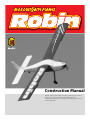
1
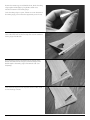
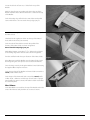
Construction Manual
Read all Safety notes before proceeding with this Construction
Manual. It is recommended that the builder read this
Construction Manual in it’s entirety before building any portion
of the supplied kit.
A Word About Safety
• The Robin is a highly engineered kit that requires the modeller to follow exact instructions to complete the
kit properly. Failure to follow the instructions provided may result in loss or damage to the kit or to persons
and property. Take your time building this kit. Attention to detail is required in completing each section.
• Do not alter/modify this kit beyond its designed specifications. Over stressing the kit in any way (i.e. too
much power or too much weight), may result in unexpected behaviour when operating. This model kit can
travel very fast; you must operate it with care for the sake of yourself and others.
• Use quality components when installing radio equipment. Do not use damaged or modified servo/radio
equipment as this may result in improper or unsafe operation of this kit.
• Always perform a radio check before operating the engine. Be sure that all radio equipment is in perfect
operating condition. All clevis connections must have safety keepers to prevent loss of control.
• If the modeller building and/or flying this model airplane is not well experienced in how to perform a radio
check or perform any of the functions related to the safe construction and/or operation of this kit, then
he/she should first consult a MAAC/AMA recognized pilot for assistance.
• Note: As the manufacturer, we provide a high-quality product for modellers to build. Great consideration
has been given to the safe operation of this kit when built properly. However, the modeller building this kit is
completely responsible for the quality of the construction. By no means, implied or otherwise, is the
manufacturer responsible for the safe construction and operation of this kit. Safe operation and the safe use
of materials and tools is the responsibility of the builder.
Let Us Help You
Important: Read
During the construction or operation of this model airplane, if at
any time you are unclear about any part of the build process or
have questions on flight, CALL US FIRST. We cannot stress this
enough. Building this kit while unsure of any particular aspects of
this kit’s construction or operation may result in unwanted flight
behaviour.
Read this Construction Manual first before starting. Familiarize
yourself with all aspects of the construction; then begin.
Do not modify or alter this kit beyond what is instructed. If
alterations are attempted, you must consult with the designer
first so that impact to the design can be assessed.
We are always here to help. You may contact us at any time
through email, letter, or by phone (during business hours).
Model Weight
To achieve the target model weight of 112oz is recommended,
but not necessary. Those who wish to add remote glow
equipment, pumps, cameras, large batteries [etc...] can do so
without adverse effects (within reason). The scratch version of the
Robin was built light by design. Some materials used in this kit
differ from the original Robin for the sake of offering a true kit and
not a scratch-build project with ribs cut out. The result: build time
is now a fraction of what was once needed. But to get down to
112oz will take a conscious effort on the part of the modeller.
Below is a list of pointers to help get to that magical number.
If Things Change
If you find there is a discrepancy in this Construction Manual
compared to information found on the plans, contact us for
clarification.
Shopping List
There are a few items you will need when building this kit:
• Lee Valley 2002 GF Cabinet Maker’s Wood Glue
• Thin CA Glue
• Epoxy Glue (12 min)
• 2 Rolls of UltraCote covering
• Dave Brown 46-50 Engine Mount
• OS .46AX Engine
• Engine Mounting Hardware
• Bisson Custom Muffler #1000
• APC 12x7 Propeller
• Fuel Tubing
• Throttle Cable
• DU-BRO Servo Arm Set
• 8oz Fuel Tank
• 21⁄2" Spinner
• 1⁄8" Fluxless Pipe Solder
• Hangar 9 Remote Glow Plug Adapter (preferred, not required)
• Clear Desk Tape
Definitions of Terms
“Dryfit” means to place a part into its position but not to apply
glue of any sort at this time.
Gluing Note:
Two types of glue will be used in the construction of this model.
When the manual instructs you to “glue", use WOOD GLUE. When
thin CA GLUE is required, the manual will specify.
Star Icon:
The STAR icon on laser-cut parts, always indicates the starboard
side of the part.
Starboard = Right hand side.
Port = Left hand side.
IV MosquitoBite Planes Robin
Weight Saving List:
• Cover the plane in UltraCote Lite covering, Solarfilm or
equivalent light weight covering - cloth covering not supported.
• Sand the Fuselage and the tips of the tail surfaces round as
shown on the supplied plans. (More material at the rear of the
plane will require more ballast in the nose.)
• Carefully glue the Tail area only with necessary amounts of glue.
• Use the supplied tail wheel or a lighter foam wheel.
• Refrain from applying elaborate graphics to the tail of the plane.
• Use a prop weight inside the spinner to set CG further out.
• Apply ballast inside the lower cowl as instructed.
• Use standard servos in the Fuselage and Wing.
• Sand the undercarriage to the profile shown on the plans.
• Use specified 12x7 APC prop.
• Trim wing and undercarriage bolts 1/4" past threaded opening.
• Use supplied Push-Nuts for all wheel axles.
• Allow 1 week of drying before covering the plane.
• Cover the Wing & Fuselage when humidity is lowest.
• Install battery in forward half of receiver box.
Covering Weight Chart (referencing manufacture’s data)
Monokote - - - - - - - - - - - - - - - - - - - - - - 78.576 g/m2 (white)
UltraCote/Oracover - - - - - - - - - - - 71.041 g/m2 (Cub Yellow)
UltraCote/Oracover Lite - - - - - - - 36.597 g/m2 (Trans. Yellow)
UltraCote/Oracover AIR (OD)- - - - - - - - - - - - - - - - - ~33 g/m2
Solarfilm- - - - - - - - - - - - - - - - - - - - - - - - - - - - - - - 50-65 g/m2
SolarSpan- - - - - - - - - - - - - - - - - - - - - - - - - - - - - - 60-80 g/m2
LiteSpan - - - - - - - - - - - - - - - - - - - - - - - - - - - - - - - - - 30 g/m2
1 Roll of Monokote = 13 sqft. or 1.207 sqm (94.84g)
1 Roll of UltraCote = 12.916 sqft. or 1.200 sqm (43.91g)
Example: 2 Rolls of UltraCote Lite saves you 3.59oz (101.86g) over
standard Monokote.
Servo Weight:
Hitec HS-475HB - - - - - - - - - - - - - - - - - - - - - - - - - - - - - - - 40g
Futaba S3004 - - - - - - - - - - - - - - - - - - - - - - - - - - - - - - - - - 37g
JR 537 - - - - - - - - - - - - - - - - - - - - - - - - - - - - - - - - - - - - - - 45g
Airtronics 94102Z - - - - - - - - - - - - - - - - - - - - - - - - - - - - - - 45g
Electric conversion is possible but not supported by this manual
at this time. Check our website for developing information
regarding this.
Table of Contents
A Word About Safety . . . . . . . . . . . . . . . . . . . . . . . . . . . . . . . . . . . . . . . . .III
Creating the Horizontal Stab (H.S.)/Elevator
18
If Things Change . . . . . . . . . . . . . . . . . . . . . . . . . . . . . . . . . . . . . . . . . . . . .IV
Creating the Horizontal Stab . . . . . . . . . . . . . . . . . . . . . . . . . . . . . . . .18
Creating the Elevator . . . . . . . . . . . . . . . . . . . . . . . . . . . . . . . . . . . . . . . .19
Elevator Horn . . . . . . . . . . . . . . . . . . . . . . . . . . . . . . . . . . . . . . . . . . . . . . .21
Shopping List
IV
Main Hatch
Definitions of Terms
IV
Forward Hatch Structure . . . . . . . . . . . . . . . . . . . . . . . . . . . . . . . . . . . .22
Aft. Hatch Structure . . . . . . . . . . . . . . . . . . . . . . . . . . . . . . . . . . . . . . . . .23
Important: Read
IV
Let Us Help You
IV
Model Weight . . . . . . . . . . . . . . . . . . . . . . . . . . . . . . . . . . . . . . . . . . . . . . .IV
Forward
1
Wing Construction . . . . . . . . . . . . . . . . . . . . . . . . . . . . . . . . . . . . . . . . . . .1
Assembling the Wing Cage . . . . . . . . . . . . . . . . . . . . . . . . . . . . . . . . . . .1
Installing Ribs . . . . . . . . . . . . . . . . . . . . . . . . . . . . . . . . . . . . . . . . . . . . . . . .2
Constructing the Leading Edge Spar . . . . . . . . . . . . . . . . . . . . . . . . . .2
Creating the Slot Lip (TE) . . . . . . . . . . . . . . . . . . . . . . . . . . . . . . . . . . . . .4
Creating the Ailerons . . . . . . . . . . . . . . . . . . . . . . . . . . . . . . . . . . . . . . . . .4
Creating the Flaps . . . . . . . . . . . . . . . . . . . . . . . . . . . . . . . . . . . . . . . . . . . .5
Sheeting the Wing . . . . . . . . . . . . . . . . . . . . . . . . . . . . . . . . . . . . . . . . . . .7
Control Cables . . . . . . . . . . . . . . . . . . . . . . . . . . . . . . . . . . . . . . . . . . . . . . . .8
Flap Hinges . . . . . . . . . . . . . . . . . . . . . . . . . . . . . . . . . . . . . . . . . . . . . . . . . .8
Wing Tips . . . . . . . . . . . . . . . . . . . . . . . . . . . . . . . . . . . . . . . . . . . . . . . . . . . . .8
Aileron Hinges . . . . . . . . . . . . . . . . . . . . . . . . . . . . . . . . . . . . . . . . . . . . . . .8
Fuselage
26
Sheeting the Vertical Stab . . . . . . . . . . . . . . . . . . . . . . . . . . . . . . . . . . .27
The Rudder . . . . . . . . . . . . . . . . . . . . . . . . . . . . . . . . . . . . . . . . . . . . . . . . .27
Mass Balance . . . . . . . . . . . . . . . . . . . . . . . . . . . . . . . . . . . . . . . . . . . . . . . .29
VI
A few notes from Andy Lennon . . . . . . . . . . . . . . . . . . . . . . . . . . . . . .VI
The Wing
Completing the Tail
22
9
Hardware . . . . . . . . . . . . . . . . . . . . . . . . . . . . . . . . . . . . . . . . . . . . . . . . . . . . .9
Pre-Assembly . . . . . . . . . . . . . . . . . . . . . . . . . . . . . . . . . . . . . . . . . . . . . . . . .9
Constructing the Fuselage . . . . . . . . . . . . . . . . . . . . . . . . . . . . . . . . . . . .9
Main Cage . . . . . . . . . . . . . . . . . . . . . . . . . . . . . . . . . . . . . . . . . . . . . . . . . . . .9
Steering Block . . . . . . . . . . . . . . . . . . . . . . . . . . . . . . . . . . . . . . . . . . . . . . .14
Elevator Cable Sleeve . . . . . . . . . . . . . . . . . . . . . . . . . . . . . . . . . . . . . . .14
Rudder Cable Sleeve . . . . . . . . . . . . . . . . . . . . . . . . . . . . . . . . . . . . . . . .14
Connecting the Fuselage Sidewalls to the Floor . . . . . . . . . . . . .15
The Tail Gear and Steering Arm . . . . . . . . . . . . . . . . . . . . . . . . . . . . . .16
Setting the Rudder Cable Position . . . . . . . . . . . . . . . . . . . . . . . . . . .17
Building the Nose
30
The Upper Cowl . . . . . . . . . . . . . . . . . . . . . . . . . . . . . . . . . . . . . . . . . . . . .30
The Lower Cowl . . . . . . . . . . . . . . . . . . . . . . . . . . . . . . . . . . . . . . . . . . . . .30
Sheeting the Lower Cowl . . . . . . . . . . . . . . . . . . . . . . . . . . . . . . . . . . .32
Sheeting the Upper Cowl . . . . . . . . . . . . . . . . . . . . . . . . . . . . . . . . . . .34
Main Landing Gear
35
Final Touches
36
Wheels . . . . . . . . . . . . . . . . . . . . . . . . . . . . . . . . . . . . . . . . . . . . . . . . . . . . . .36
Gluing the Snaps . . . . . . . . . . . . . . . . . . . . . . . . . . . . . . . . . . . . . . . . . . . .36
Setting Centre of Gravity (CG) . . . . . . . . . . . . . . . . . . . . . . . . . . . . . . .36
Fuel Tank . . . . . . . . . . . . . . . . . . . . . . . . . . . . . . . . . . . . . . . . . . . . . . . . . . . .36
Engine and Muffler . . . . . . . . . . . . . . . . . . . . . . . . . . . . . . . . . . . . . . . . . .36
Covering the Nose and Sealing the Lower Cowl . . . . . . . . . . . . .36
Notes
37
MosquitoBite Planes Robin V
Forward
A few notes from Andy Lennon
The Robin is a versatile model airplane, with a wide speed range, that
can take off and land in either of two modes: the conventional mode or
the STOL mode (short take off and landing) – made possible by several
unique features which are described below. It is a “fun” airplane.
The wing features large slotted flaps that cover 65% of its trailing edge
and when extended 40 degrees, virtually double the lift of that 65% of
wing area. The wing’s airfoil is the Eppler E197. It’s aspect ratio (ratio of
span to chord) is 6. It has low profile drag and a gentle stall at 20
degrees AOA (angles of attack) out of ground effect. Its zero lift AOA is
minus 2 degrees.
Ahead of the ailerons, the E197 airfoil is modified to NASA development
leading edge extensions and droop that do three things: the stall is
delayed a further 9 degrees, aileron control at high angles of attack is
effective and there is no tip-stalling, important for STOL landings.
The fuselage, when the model is on its three wheels, is inclined upward
10 degrees. The wing is set at plus 2 degrees to the centreline and is
therefore at 12 degrees angle of attack; moving forward, the wing lift is
close to the maximum, but below the stall. With flaps half extended and
in ground effect, the stall is at 17 degrees. This permits the short take off.
The landing gear in conventional or “tail dragged”. With all three wheels
firmly on the ground, the model is directionally stable and is
maneuvered by the steerable tail wheel, linked to the rudder control.
With the tail wheel off the ground, however, the model is directionally
unstable; this calls for careful rudder action to prevent the model from
veering which it is prone to do!
The recommended power for the Robin is the OS MAX .46AX engine that
turns the recommended APC 12X7 prop at 10,000 rpm. producing thrust
estimated to equal the model’s fuelled weight. This provides a steep
climb. Minimum level flight speed, flaps fully extended, is 20 mph and 80
mph in full speed level flight, flaps up. For low drag, the engine is
enclosed in a ducted cowling. The lower half of this cowl is easily
removed and replaced for engine servicing, such as glow plug changes.
A remote jack permits glow plug lighting safely away from the lethal
prop. Engine cooling has not been a problem.
The horizontal tail is positioned low in the fuselage where it is in the
prop’s powerful slip stream. The elevators are 40% of the tail’s area and
when raised, cause the tail wheel to rest firmly on the ground under slip
stream pressure. To taxi, hold “up-elevator” which provides good steering
and prevents “noseovers” should the main wheels meet an obstruction
like long grass. The flaps, when extended, create considerable
turbulence. The large dorsal fin ahead of the vertical tail provides good
directional control despite the turbulence.
A 6 channel transmitter-receiver is recommended with a 3 position snap
switch for flap control: up, 20 degrees down, and 40 degrees down.
The ailerons have heavy differential (20 degrees up and 10 degrees down)
and are top hinged with modified Frise features that eliminate adverse
yaw. The model turns on ailerons alone without rudder input.
The Robin is spirally stable. Put in 20 degree bank and controls centred, it
will return to level flight on its own. It will fly inverted, but requires a
healthy amount of down elevator (inverted down elevator is up-elevator).
VI MosquitoBite Planes Robin
The two modes of take off are conventional and STOL. In the
conventional, the model is pointed upwind, flaps half extended, and the
throttle slowly opened. As the model accelerates, the tail comes up and
the directional instability raises its ugly head. Torque and gyroscopic
precession cause a swing to the left, calling for just the right amount of
rudder. Over control results in a swing to the right and danger of a
ground loop. This is not imaginary – it has happened! At 20 feet of
altitude, raise the flaps, level off, and the plane is up and away.
For the preferred STOL take off, point the model into the wind, lower half
flap, hold enough up elevator to keep the tail-wheel firmly on the
ground and open the throttle wide. On a calm day, take off run is under
4 feet; on a day with wind of 10 to 15 mph, the take off is almost
instantaneous followed by a steep climb. At 20 feet, raise the flaps, level
off and the plane is away. Directional control on the ground is good and
torque and gyroscopic precession are avoided.
There are two types of landing: the low wind STOL landing and the high
wind landing. On a low wind day, do not try to land flaps up. The glide is
fast and flat; overshooting the landing area is probable. Instead throttle
to idle, lower full flap; the added lift and drag permits steep approaches
at relatively low speeds. There is little or no change in the model’s
attitude with flaps lowered fully – just a noticeable reduction in speed.
The objective is to have all three wheels touch down simultaneously at a
speed just above the stall, which is (flaps fully down and in ground
effect) 14 degrees. At an AOA of 12 degrees, the plane is just below the
stall. Ground run 4 feet. This is when the “no tip-stall” feature is so
valuable. The wing area ahead of the flaps may be stalled but the two
outer panels are still lifting with effective aileron control.
On a windy day, land flaps up with a bit of power. A model flying at 30
mph into a wind of 15 mph has a ground speed of 15 mph. Rather than
a full stall landing, land on the main wheels first, closing the throttle to
idle just before touchdown.
The Robin will spin but very reluctantly; the spin has to be forced by full
up-elevator and full rudder offset. After 3 or 4 turns, the spin will convert
to a fast spiral dive, speeds of well over 100 mph are possible - the model
has low drag - so do not omit the mass balancing of the ailerons,
elevators and rudder which will prevent “flutter” at high speeds.
Enjoy the Robin and happy landings!
- AGL
In a later note, Andy offered more information about landing with
full flaps:
Lowering flaps while at altitude will create substantial downwash. The
downwash will hit the horizontal tail and influence it’s attitude. Pilots
must be careful to note that while landing with full flaps, you will
eventually come into ground effect. At that point, the downwash over
the horizontal tail will be reduced due to the pressure from the ground.
The Robin will pitch down slightly as the downwash pressure eases off
the horizontal tail, so pilots should be ready for it when approaching
with full flaps.
The Wing
Wing Construction
Glue and clamp together Main Centre Spar layers, to create the
laminated Main Centre Spar and Rear Centre Spar. Leave to dry.
The three pieces that make up the Main Centre Spar must be
glued together very precisely. Each of the 3 pieces have a slight
lengthwise curve. Ensure the insides of the curves face each other
(this cancels out any over-all curve) and glue together.
Repeat this method to laminate the two layers of the Rear Centre
Spar and the two layers of the Wing Bolt Beam.
Assembling the Wing Cage
The gluing of the Wing Cage must be done quite rapidly.
Therefore, we suggest you familiarize yourself with the Cage
assembly by dryfitting the following pieces as shown in Figure 1
• Main Centre Spar - 3 parts
• Rear Centre Spar - 2 parts
• Wing Servo Tray
• Rib A (x2)
• Wing Bolt Beam - 2 parts
If any parts are too snug, perform minimal sanding.
Disassemble and continue with these gluing instructions:
Along the front and back edges of the Wing Servo Tray, run a line
of glue. Immediately connect the Main Centre Spar to the Tray’s
front, and the Rear Centre Spar to the Tray’s back.
Fig 1
Glue the rear edge of the Wing Bolt Beam and install in place
along the front of the Main Centre Spar.
Run a line of glue along both side edges of the Wing Servo Tray,
and along the sides edges of the Wing Bolt Beam.
Slide Rib A along the Spars. The letter “A” on each Rib, should both
be facing the Wing Servo Tray. Connect both Rib A parts into the
tabs of the Wing Servo Tray and the Wing Bolt Beam.
Before the Wing Cage cures, place a heavy weight in the centre of
the Wing Servo Tray to ensure all parts dry flat and square.
MosquitoBite Planes Robin 1
Installing Ribs
Place Main Spar upside down on its top edge. Along side it, place
a 3⁄8" x 3⁄16" stick - wide side down. Dryfit Rib B into the first slot so
that it holds the balsa stick against the Main Spar. See Figure 2.
Note: In Figure 2, Rib B and the Main Spar are shown upside
down, as constructed. Also note that the end of the stick must
extend slightly past the end of the Main Spar. This will be
trimmed later.
Continue to dryfit Ribs C to J.
Dryfit the remaining 3/8" x 3/16" stick along the Main Spar. Glue with
thin CA, the upper and lower sticks along the Main Spar. (Using
wood glue here would warp the wing due to its moisture
content.) Watch the Main Spar doesn’t develop a curve.
Fig 2
Repeat instructions to create the opposite side of the wing.
(Be careful not to make two left wings.)
Constructing the Leading Edge Spar
Locate Rib F1. (half a rib)
Install Rib F1 against the forward half of Rib F, between
Ribs F and E.
F1
To install Leading Edge Spar, you must first ensure that all ribs are
evenly spaced. Therefore, use the Rear Spar as a tool and dryfit
the Rear Spar into the rear slots of all ribs. Then place the other
Rear Spar over the leading edge of all Ribs to ensure the spacing
is correct. See Figure 3.
Do note Glue the Rear Spars yet.
Fig 3
Glue (wood glue) a 3/16" square stick to the leading edges of Ribs F
to J. Use masking tape to hold the stick in place while glue cures.
Remove the two temporary Rear Spars.
Once the leading edge’s stick has cured, remove the tape.
Repeat for the opposite side of the wing.
2 MosquitoBite Planes Robin
Glue Rib G1 on the outboard side of Rib G.
Fig 4
Dryfit the upper and the lower 1/4" x 1/8" sticks into the slots of
every Rib behind the Rear Spar. (See Plan Sheet 2)
Slide Rib G1 in
Glue two Aileron Cable Anchors into the slots of Rib G1 as shown
in Figure 4.
Trim flush the sticks that protrude from the inboard upper and
lower Main Spar and Rear Spar, as shown in Figure 5.
Repeat the “Constructing the Leading Edge Spar” instructions to
create the opposite side of the wing.
Fig 5
Test the connection of each Wing-side to the Wing Cage,
as shown in Figures 6 and 7.
Fig 6
Glue the Wings to the Wing Cage in all places where contact is made.
Using thin CA, glue the Rear Spar and its upper and lower balsa
sticks in place.
Fig 7
Dryfit a 3/16" square stick to the leading edge of each Wing from
Rib A to F1(the half-rib). See plan sheet 2 for details.
Use masking tape to hold each stick in place while glue cures.
Glue both Flap Cable Anchors into Rib D. They line up with the
hole on the Rear Spar. Repeat for the opposite side of the wing.
Apply a bead of glue to the joint of each Rib and Main Spar as
well as to the joint of each Rib and Rear Spar.
MosquitoBite Planes Robin 3
Locate all eight Flap Support Arms.
Glue two Flap Support Arms to either side of Rib C and to either
side of Rib E as shown in Figure 8.
Before the glue cures, use a 3/32" wire to align the hinge holes as
shown in Figure 9. Repeat for the opposite side of the wing.
Fig 9
Fig 8
Creating the Slot Lip (TE)
Locate the Trailing Edge Stock (3/16" x 3/4"). Cut two pieces,
each 22" long.
Apply glue to the trailing edge of Rib A to Rib G on both sides of
the Wing, and install both pieces of Trailing Edge Stock.
Clamp until cured.
Creating the Ailerons
Locate two Aileron Base Sheets, eight Aileron Ribs, two Aileron
Horns, two Aileron Spars and two Aileron Top Sheets.
Build both Ailerons at the same time (facing each other) to
prevent making two left Ailerons.
On the Base Sheets, position the Aileron Ribs and Aileron Horns in
their slots. See Figure 10.
Dryfit the Aileron Spar into the End Slots of all Aileron Ribs and
Aileron Horns.
Making sure not to glue the Spar, apply thin CA to the base of all
the Aileron Ribs and Aileron Horns. (We don’t want to glue the
spar in yet.)
Remove the Spar and apply wood glue to the Aileron Ribs and to
the short edges of the Aileron Horns. Replace the Aileron Spar.
(Note: Ensure that no wood glue contacts the Aileron Base Sheet
to avoid warping.)
4 MosquitoBite Planes Robin
Fig 10
Aileron Horn
Aileron Rib
Position each Aileron at the edge of a table and use a sanding
block to sand the edge of the Aileron Base Sheet to a fine point.
Locate the two Aileron Top Sheets.
Dryfit each Top Sheet along the upper tabs of the Aileron
Ribs/Horn.
Wick thin CA glue into the tabs of each Aileron Rib/Horn. (Note:
To avoid a twisted Aileron, hold the assembly down on a flat
surface as CA glue is applied.)
Once the Top Sheet has cured, sand the trailing edge to almost a
fine point. Cover Aileron with Ultracote and install the Mass
Balance along the full width of the Aileron. See Plan Sheet 2.
Creating the Flaps
Locate two Flap Base Sheets, eight Flap Ribs, two Flap Horns, four
Flap Horn Supports and four Flap Pivot Ribs.
On the Base Sheets, dryfit the Flap Ribs in their slots as seen on
Plans Sheet 2. Use thin CA to glue in place.
Build both Flaps at the same time to prevent making two
left Flaps.
Into the centre set of slots, dryfit the Flap Horn with Flap Horn
Supports on either side. Use thin CA to glue in place.
MosquitoBite Planes Robin 5
Dryfit Flap Pivot Ribs into the two remaining slots, then dryfit
both Flap assemblies into the trailing edge of the Wing so that
the Flap Pivot Ribs drop into the Flap Support Arms, as shown in
Figure 11.
Using thin CA, glue the back tab of each Flap Pivot Rib and just
the rear portion of each Flap Pivot Rib. Be sure no glue contacts
the Flap Support Arms. When glue cures, remove both Flap
assemblies and complete the gluing of each Flap Pivot Rib.
CA Glue
Fig 11
Sand the top side of each Flap trailing edge to a fine point – in
the same fashion as done with the Ailerons. See Plan Sheet 2.
Cut a sheet of 1/16" balsa sheeting the length of the Flap, by 31⁄2".
Lay the Flap upside down on top of the 1/16" sheeting. Position the
sheeting 1⁄4" past the Flap Base Sheet. Use thin CA to glue along
the trailing edge.
CA glue trailing edge
When the trailing edge has cured, sneak a drop of CA on top of
each Rib while still working on a flat surface.
Rock the Flap forward until the Flap Horn contacts the top
sheeting. Mark the sheeting on either side of the Flap Horn to
indicate the Horn Opening.
Cut a small slot (about /2" long) out of the sheeting to allow the
Horn to emerge. See Figure 12.
Sneak in CA
1
Use clamps on the leading edge of every Rib to hold the sheeting
against the Flap Base Sheet.
Now is the time to manually adjust the Flap to remove any
warping caused by handling.
Use thin CA to glue the leading edge of the Flap. Remove clamps
when glue has cured.
Sand the leading edge of each Flap to match the profile on Plans
Sheet 2.
Cover the main Flap Surface with Ultracote. Do not cover the
Pivot Rib.
6 MosquitoBite Planes Robin
Fig 12
Test fit the Flap in its position on the Wing. If the hole in the Flap
Pivot Rib and the Flap Support Arm do not line up, sand the
underside of the trailing edge stock to allow more room for the
Flap to enter. (See Figure 13)
Sand and profile the Flap Support Arms to match the profile
shown on Plan Sheet 2.
Locate the 8 Sheeting Supports. (See Plan Sheet 2.) Glue them
onto the sides of each Flap Support Arm. (See Figure 13)
Sheeting Supports
Sand Trailing Edge
Fig 13
Sheeting the Wing
Wing shown inverted.
The sheeting of the Wing is done using common methods. There
are, however, some details that need addressing. Refer to Plan
sheet 2 for details.
To begin, cut a strip of 1/16" sheeting wide enough to cover the top
of the Rear Spar and to butt up against the Slot Lip TE stock. This
goes the full length of each side of the Wing. Let the sheeting
hang over to give support for the Lower Aileron Sheeting (A).
C
For the Lower Aileron section, cut and glue on a strip of sheeting
(B). Shave the edge of this sheeting to best fit the profile (C).
B
Fig 14
Before sheeting the Lower Wing (Flap section), we will make
some supports; cut strips of 1/16" balsa (the height about 1/2 " - see
Plan Sheet 2) to snugly fit between the rear of each Rib. (D) Use
thin CA to glue in place.
A
The remainder of the Wing is sheeted in the traditional fashion:
D-tube and cap strips with 1/16" balsa, according to Plan Sheet 2.
To sheet the Lower Wing (Flap section), measure and cut 1/16" balsa
to fit around the Flap Supports. See Plan Sheet 2 for sheeting
width. Glue on with thin CA. (See E.)
A small insert is needed for support. Cut a long, thin section of
sheeting. (See Figure 15 on next page.) Glue in with thin CA.
E
D
MosquitoBite Planes Robin 7
Control Cables
The supplied cables should be distributed as follows: Two 36"
cable/sleeves are for the Rudder and Elevator. Each 48"
cable/sleeve = 1 Aileron and 1 Flap for one side of the Wing.
Install an empty 48" Sleeve into the Aileron cable path, and trim.
The remainder is for the Flap control. Do not cut both 48" cables
the same - the port side of the wing is a longer cable length.
You will have to make an opening in the Lower Aileron section of
the Wing’s sheeting for the Cable to exit. (See Figure. 16)
Fig 15
Fig 16
Flap Hinges
With a hobby rail saw, cut the supplied brass tubing and the 3⁄32"
rod to make the 4 sets of hinges. Each tube length = the width of
the Flap Pivot Rib. (When cutting these tubes, leave a little extra and sand the edges clean - Figure 17.) Each rod length should be
1
⁄4" long. Insert the tube into the Flap Pivot Rib. The rod goes
through the tube, after the Flap is installed.
Install the 1⁄16" balsa Fairings. Once glued in place, sand to the
profile shown on Plan Sheet 2. To secure the brass tube joints in
place, cover the Flap Support Arms with Ultracote.
Fig 17
Wing Tips
Locate the supplied Wingtips. These are extra deep to allow
trimming. Install the Wingtips over the Wing Tip Ribs and glue
with epoxy. Trim and sand the WTR inside face. Study Plan Sheet
2 for positioning of the WTR and the Wing Tips.
Do not attempt to cover the Wing Tips, they will deform from the
heat. Paint them instead, and then Install.
Flap
Pivot
Rib
Install all Wing Servos and test all Flaps and Ailerons. (Temporarily
use desk tape to attach the Ailerons) Make sure everything
operates smoothly. Once everything is in check, cover the Wing.
Aileron Hinges
After the Wing has been fully covered, create the Aileron Hinges.
These will be made of Ultracote. With an Aileron fully deflected
down, iron a long thin strip of covering across the joint of the
Wing and the Aileron. To prevent binding, allow a small gap
between the Aileron and the Wing, remembering that the gap
will shrink when the covering is heated.
Next, fully deflect the Aileron up. Iron a long thin strip of covering
across the inside edge of the Wing and Aileron, making sure this
strip makes contact with the top covering in the middle.
8 MosquitoBite Planes Robin
Fairing
Flap
Support
Arm
Fuselage
Locate the following:
• Battery Box Walls
• Battery Box Floor
• Firewalls: F2A and F2B
• Formers: F3B to F13
• Fuselage Bolt Plates, three A & two B parts.
• Undercarriage Mounts, A and B
• Side Support Walls
• Main Servo Tray
Hardware
• Airvent Sidewalls, two A & two B parts.
• Fuel Tank Floor
• Fuselage Sidewalls
• Fuselage Floor
• Hatch Bolt Assembly
• Wing Saddle Doublers
• Two Hatch Hooks
• Tail Steering Block Parts
4 Cable with Sleeve, Steering Arm, and 2
Clevises.
Pre-Assembly
The Fuselage Sidewalls and Floor need to be
pre-assembled as shown below. Ensure that
both Sidewalls are perfectly identical to each
other before using.
Constructing the Fuselage
Locate both parts of the Firewall - Formers F2A and F2B.
Place F2A and F2B back to back . The writing on both formers
should face outward.
Glue and clamp these together, ensuring all holes are aligned.
F2B is intentionally wider and taller than F2A. Set aside to cure.
Main Cage
Locate the three parts of the Battery Box. Refer to Figure 18: Glue
the Battery Box sides to the floor.
Locate Formers F5B and F6A.
Apply glue to the inside edges of both F5B and F6A.
Insert the Battery Box through them. (F6A goes nearest the upper
hooks on the Battery Box.) Lift the Battery Box up into position
and push out the Box walls to fit onto the tabs of the Formers,
F5B and F6A.
Fig 18
MosquitoBite Planes Robin 9
Locate the Fuselage Bolt Plates, three A and two B parts.
Fig 19
Sandwich one B part between both A parts and test fit this
laminated beam into the top slots of F5B before applying glue.
Use lots of glue to laminate all three beams altogether and glue
them into the slots along the top of F5B as shown in Figure 19.
A
Glue the long edge of the laminated Beam and the edges of the
Battery Box and install F5A on these glued edges. Use large pliers
to coax the top of F5A to connect with the Beam properly.
B
Laminate the remaining two Fuselage Bolt Plates, one A and one
B. With lots of glue, install this laminated Bolt Beam to the back of
F6A.
Glue the long edge of this last laminated beam and the edges of
the Battery Box and then install F6B. Use pliers to coax the top of
F6B to connect with the Beam.
Locate the Undercarriage Mounts, A and B, and the two Side
Support Walls.
Fig 20
Glue Mounts A and B face to face, making sure the holes are in
perfect alignment.
Before the glue cures, glue in place the Side Support Walls, as
shown in Figure 20.
Apply glue to the edge of the Undercarriage Mount (the edge
opposite the holes) and to the edges of the Side Support Walls.
Install this into the lower slots on F5A. See Figure 21.
10 MosquitoBite Planes Robin
Fig 21
Locate Main Servo Tray.
Glue it into the slots midway up F5A, as shown in Figure 22.
Apply glue to the exposed edges of the Undercarriage Mount,
the Side Support Walls and the Main Servo Tray.
Install F4 on these glued edges.
Fig 22
Before glue cures, temporarily dryfit the whole assembly into
the slots of both Fuselage Sidewalls and Fuselage Floor - ensuring
all parts cure in perfect alignment. See Figure 23.
Fig 23
Locate the Airvent Sidewalls. (two “A” and two “B” parts)
Glue each A to a B, keeping the centre holes aligned.
Glue each laminated Airvent Sidewall into the slots on F3B, as
shown in Figure 24. (Parts A are closest to the F3B centre hole.)
Fig 24
On both Airvent Sidewalls, apply glue to the long edges that
sport tabs, and install the Fuel Tank Floor as shown in Figure 25.
Fig 25
Fuel Tank Floor
MosquitoBite Planes Robin 11
Remove the Fuselage Sidewalls & Floor from the main structure.
Locate a 3/8" square stick. Install it vertically down between the
edges of F5A and F5B. Trim the lower part of the stick to match
the Formers’ diagonally cut bottoms.
At the top, you must cut out part of the stick to match the
Former shape as well. Repeat for the opposite side.
Repeat this process again between F6A and F6B. See Figure 26
which shows only the right side done between the two sets of
Formers.
Fig 26
Using tape, temporarily install F3A. Glue both Fuselage Sidewalls
onto the Formers assembly. Turn on its side and apply weight.
Allow time for curing.
Apply glue to the rear edge of the Fuel Tank Floor and to the two
side edges of F3B.
Plug the end of the Fuel Tank Floor into F4 while fitting F3B into
the Fuselage Sidewalls as shown in Figure 27.
Fig 27
Locate F7 and the four pieces for the Hatch Bolt Assembly (HB1, HB2
and 2x HB3)
Glue face to face, HB1 and HB2 ensuring the bolt holes are
aligned. This is your Bolt Plate.
Glue the Bolt Plate into both HB3 parts.
12 MosquitoBite Planes Robin
It is VERY IMPORTANT that you attach the Hatch Bolt Assembly to
the correct side of F7. It must attach to the forward side of F7. See
Figure 28. or see Plan Sheet 1. Glue only when you are certain.
Fig 28
Glue the edges of F7 and install into the Fuselage Sidewalls. The
Hatch Bolt Assembly must be pointing forward and be at the top.
See Figure 29.
Fig 29
If your Fuel Tank Floor has cured into F4, it is time to glue the
laminated Firewall to the forward end of the Fuel Tank Floor.
Apply glue to the end of the Fuel Tank Floor. (Note: We are NOT
gluing the Fuselage Sidewalls to the Firewall until the Firewall has
cured to the Fuel Tank Floor.)
Now attach the Firewall to the end of the Fuel Tank Floor. Clamp
well enough to allow handling.
Locate the two Wing Saddle Doublers.
Fig 30
Dryfit them into position (along the inside of the Fuselage, top)
and glue with thin CA. See Figure 30.
When the Fuel Tank Floor has cured with the Firewall, glue along
the side edges of the Firewall and press Fuselage Sidewalls onto
the tabs of the Firewall. Clamp until glue cures.
When the Firewall sides have cured, cut two pieces of 1/2" x 3/16"
balsa about 10" long each.
Fig 31
Slide each piece along the upper inside of the Fuselage Sidewall,
starting at the Firewall, and butting up against F4.
Trim each stick flush with the firewall. See Figure 31. Use thin CA
to secure each stick in place.
Trim flush
Cut two more 1/2" x 3/16" wide sticks of balsa, each about 21/4" long.
Shape each piece to fit snugly between the forward end of the
Wing Saddle Doubler and the recently installed stick, as shown in
Figure 32. Repeat for the opposite side.
Locate the two Hatch Hooks and glue into the rear slots of F2B.
The curved corner of each Hatch Hook must be along the
bottom side. See Figure 33 & Plan Sheet 1.
Fig 32
Fig 33
MosquitoBite Planes Robin 13
Steering Block
Locate F8 and F9. Apply glue to their side edges. Install each
between the Fuselage Sidewalls, making sure that the “Star” is on
the starboard side. Clamp until glue cures.
Refer to diagram on Plan Sheet 1 for the Tail Steering Block and
assemble it with wood glue. Be sure to glue the assembly on the
back side of F10. When glue is cured, Install F10 into position. See
Figure 34.
Glue the sides of F11B. The side hole goes on the starboard side.
Install and clamp until cured. Temporarily dryfit the Fuselage
Floor; this will ensure F11B cures at the correct angle. Remove
when F11B has cured.
Fig 34
Elevator Cable Sleeve
Lay the supplied 36" Cable Sleeve on the plans and cut the
Elevator Sleeve to length. Install this in the hole of F5A on the
port side as shown in Figure 35.
This Sleeve must follow the Elevator Cable Path shown on Plan
Sheet 1. Glue in place with thin CA. See Figure 36.
Rudder Cable Sleeve
Lay the supplied 36" Cable Sleeve on the plans and cut the
forward (longest) Rudder Sleeve to length. Install this in the
starboard hole of F5A, and guide it along the Rudder Cable Path
shown on Plan Sheet 1. Glue this forward section of Rudder
Sleeve in place with thin CA. See Figure 36.
Elevator Cable
Fig 36
Fig 35
Rudder Cable
F11B
Install three Servos into the Fuselage Servo Tray, in the orientation
shown in Figure 35 and Plan Sheet 1 .
Trim to length the small, remaining section of Cable Sleeve for
the Rudder Cable/Tail Wheel, and dryfit it, as shown on Plan
Sheet 1. It exits through the Fuselage Sidewall; see Figures 36 and
37 to help guide you in creating this opening.
Install the full 36" of Rudder Cable Wire.
F11B
Use thin CA to glue the remaining Rudder Cable Sleeve in place.
Fig 37
14 MosquitoBite Planes Robin
Lay your supplied Cable Wire on Plan Sheet 1 and cut the Cable
Wire for the Elevator to length.
On the Elevator Cable Wire, solder a Solder Link to the rear end,
and install it into the Elevator Cable Sleeve.
With thin CA, glue in the Fuselage Floor making certain that the
hole behind F10 is on the port side. (Do not apply glue to the
bottom of F4 and F5A in a way that would seal the lateral lasercut lines in the Fuselage Floor. These pre-cut slits must be kept
clear of glue for a later building step.)
Tape into position both small Fuselage Sidewalls – Parts D.
Dryfit F12. Tape across the ends of the Sidewalls so that they
hug F12.
Dryfit the Fuselage Top Sheet. Tape the Top Sheet down against
the Sidewalls, making sure no tape nears the Fuselage Floor as
that area will soon be sanded.
Connecting the Fuselage Sidewalls to the Floor
Use a sanding block to sand to 45 degrees, the entire length of
both the lower edge of each Fuselage Sidewall and the edges of
the Fuselage Floor.
Cut strips of 3/16" sheeting, about 2" wide. Cut enough to span the
length of the plane, twice. These strips will cover the section
between the Fuselage Sidewalls and the Floor.
Tack the stripping with thin CA, near F5 to start. Tack your way
both forward and backward. This will help you avoid any potential
buckling. Be careful not to get glue on F12 as it will need to be
removed later when installing the Tail. Also, make sure to keep
F12 vertical while gluing - it sets the tail strait.
In order to attach the second corner strip, use a sanding block to
slowly sand back the lower, rear corner of the first strip. Stop
when the second strip will connect cleanly with the Floor,
Sidewall and newly sanded first strip. See Figure 38.
Fig 38
Using thin CA, glue on the second strip of balsa, employing the
same method as you did for the first strip. Do not apply strips to
the top corners yet.
Carefully trim back the excess 3/16" material and then use a
sanding block to sand the edges of the strips to match the angle
of the Floor/Sidewalls as shown in Figure 39.
Some modellers can skilfully use a palm sander to speed this up.
Fig 39
MosquitoBite Planes Robin 15
Sand the protruding Rudder Control Cable Sleeve flush with the
Fuselage Sidewall. The Cable will need to be withdrawn from this
section of Rudder Sleeve.
Remove the remaining tape and set aside Fuselage Sidewalls
Parts D.
Locate little F11A. Dryfit F11A into the Fuselage Top Sheet slot,
above F11B. Glue with thin CA.
Except for F12, CA glue the Fuselage Top Sheet to all Formers.
Remove only the tape that holds the Fuselage Top Sheet against
the Sidewalls. Now the tricky step: without getting CA on F12, use
thin CA to glue the Fuselage Top Sheet to the Fuselage Sidewalls
where they connect.
F11A
The Tail Gear and Steering Arm
Locate the Steering Arm.
Cut back the arm’s length, leaving only one hole. See Figure 40.
Fig 40
Install the EZ Connector and its screw.
We recommend replacing the slotted screw from the Steering
Arm with the black socket head bolt which we have supplied.
Slide the Rudder Cable into the EZ Connector on the Rudder
Servo Arm. Partially pull the back end of the Rudder Cable out of
the Fuselage through the large Horizontal Stab opening.
Slide the Cable through the EZ Connector on the Steering Arm.
Match the orientation of your Steering Arm shown in Figure 41.
Carefully pull the Cable and Steering Arm back into the Fuselage.
Manoeuvre the Steering Arm into the Tail Wheel Block.
Fig 41
16 MosquitoBite Planes Robin
To make the Tail Gear, bend the supplied 1/8" wire according to the
diagrams on Plan Sheet 1. Careful: Don’t bend corners too sharp.
The shape on the plans is not critical. The shape shown here is
acceptable.
Install the Tail Gear through the Fuselage Floor, into Tail Wheel
Block, and through the Steering Arm. Be sure the Tail Gear is
raked backwards not forward.
Set the Tail Gear so that it is parallel to the Steering Arm.
Now tighten the Steering Arm screw really tight.
Setting the Rudder Cable Position
Loosen the EZ Connector on the Steering Arm and pull the
Rudder Cable back through the second section of Rudder Sleeve.
Pull the Cable back so that it stops 1" before the end of the
Fuselage Sidewall as shown in Figure 42 .
Fig 42
1"
Tighten the EZ Connector on the Steering Arm and the Cable
Connector on the Servo - while the Steering Arm is parallel
with F10.
MosquitoBite Planes Robin 17
Creating the Horizontal Stab
(H.S.)/Elevator
H.S. shown upside down
Creating the Horizontal Stab
Locate the following:
• 2 Horizontal Stab Base Sheets
• 2 Horizontal Stab Top Sheets
• 10 Horizontal Stab Ribs
• 2 Horizontal Stab Doublers
• Parts A and B of Horizontal Spar
Preassemble parts A and B of the H.S. Spar.
Build both halves of the Horizontal Stab (H.S.) at the same time.
Locate the two H.S. Top Sheets. They are slightly deeper than the
H.S. Base Sheets.
Fig 43
On each H.S. Top Sheet, use thin CA to glue on the H.S. Ribs (5 per
side). Ribs should sit within the depth of the base. If a Rib extends
beyond one side, it is facing the wrong way.
Suggestions: Start with a Rib closest to the centre of each Base
Sheet instead of Ribs at the ends. Keep each Rib as vertical as
possible as you apply CA to its base.
Gently push the Horizontal Stab Spar onto the rear tabs of the
H.S. Ribs. See Figure 43.
H.S. shown upside down
Use thin CA to glue the H.S. Spar along the H.S. Top Sheet.
Locate the two Horizontal 3⁄16" Stab Doublers. Use thin CA glue to
glue each Doubler to each of the inner Stab Ribs. See Figure 44.
Locate 1/4" x 1/4" triangle stock.
Measure and cut a piece the full length of the Horizontal Stab.
Position this piece on the H.S. Top Sheet, along the back of the
H.S. Spar. Use thin CA to glue in place. Be careful not to introduce
twisting to your Stab as you handle it.
Fig 44
Cut two pieces of 1/16" scrap balsa, 11/8" x 3". Be sure the 11/8" grain
follows the same grain direction of the H. Stab Top Sheet.
Position this piece between the two H.S. Doublers, on the two
visible lips of the Top Sheet. Use thin CA to glue in place.
See Figure 45.
Put aside the second 11/8" x 3" sheeting to do the opposite side,
after the H.S. Top Sheet is on.
Fig 45
18 MosquitoBite Planes Robin
Dryfit one H.S. Base Sheet onto the upper tabs of the H.S. Ribs.
Use thin CA to glue this Base Sheet in place. Commence the
gluing along the H.S. Spar.
When the Base Sheet tab opening, sides and Spar edges are
glued, pinch together the H.S. Base Sheet and Top Sheet. Use thin
CA to glue the forward tips of these two pieces together.
Finally, to close the centre of the Horizontal Stab, locate the
reserved 11⁄8" x 3" piece of balsa sheeting. Slide into the opening
between the two Base Sheets by cutting open two small slits
along the H.S. leading edge to accommodate its width.
H.S. shown upside down
Once in place, use something thin and strong to push the balsa
scrap up against the inside of the Base Sheets. Use thin CA glue
to secure it in place.
To create the tips of the Horizontal Stab, first sand each end of
the H.S. flush (using block sander).
Next, locate the 10 balsa H.S. Tips. Use CA to glue four H.S. Tips to
each other, and finally to glue this laminated H.S. Tip to each end
of the Horizontal Stab.
Sand the leading edge of your Horizontal Stab to match the
profile shown on Plans Sheet 1.
H.S. shown upside down
Creating the Elevator
Locate:
• 2 Elevator Base Sheets. (deeper than the Top Sheets.)
• 2 Elevator Top Sheets
• 10 Elevator Ribs
• 2 Elevator Spars
• 4 Elevator Doublers
On each Elevator Top Sheet, you will use thin CA to glue on the
Elevator Ribs – 5 per side. Ribs should sit within the depth of the
base. If a Rib extends beyond one side, it is facing the wrong way.
Keep each Rib as vertical as possible as you apply CA to its base.
Top Sheets Shown
MosquitoBite Planes Robin 19
Dryfit the Elevator Spars onto the ends of the Elevator Ribs.
Apply thin CA glue to the base of the Elevator Spar, where it
contacts the Elevator Base Sheet.
Locate the four 3/16" Elevator Doublers.
On each inside end of the Elevator, glue on two Doublers with
thin CA. The Elevator Doublers will extend beyond the end of the
Elevator Top Sheet slightly.
Sand Line
Sand the trailing edge of the Elevator to a fine point.
Install the Elevator Base Sheet. Use thin CA to first glue the tabs,
then where it connects to the trailing edge, and finally the
remaining three sides.
Sand the trailing edge of the Base Sheet to match the angle of
the Top Sheet. See Plans Sheet 2.
Sand the end of the Doubler to match the angled Elevator
end profile.
Use thin CA to glue five Elevator Tips onto the outer end of each
Elevator. See Figure 46. (Note: the angled end is the inner end of
each Elevator.)
Sand smooth the laminated Elevator Tips.
Fig 46
Temporarily tape the Elevators to the Horizontal Stab.
Flip the Horizontal Stab over and let the Elevators hang over the
edge of your work surface.
Use a 3⁄32 drill bit to drill a hole into each Elevator, as indicated by
the arrows in Figure 47.
Fig 47
20 MosquitoBite Planes Robin
Elevator Horn
Locate the supplied 3⁄32" wire and brass channel stock.
Cut the brass channel stock to 11⁄8" long and remove 1⁄2" of one of
the brass walls as shown in Figure 48.
On that same end (where the wall was cut away), drill a 1/16" hole
and drill a 3/32" hole on the other side.
Removed
wall section
Bend the 3/32" wire to the exact width of the distance between the
two holes that were drilled into the Elevator. It should resemble
Figure 48.
Fig 48
Slide the brass channel stock down the bent wire to the
midpoint.
Fig 49
In preparation for soldering, pinch the walls below the wire with a
pair of pliers.
Solder the brass channel stock in position as shown in Figure 49.
Using epoxy glue, install bent-wire assembly into the drilled holes
of both Elevators as seen in Figure 50. (Test fit first to ensure easy
fit, and roughen the wire to give “bite” for the glue) Ensure the
Elevators are lying flat while the epoxy cures.
Once the epoxy glue has cured, proceed with applying Ultracote
covering to create the Elevator hinges (Use the same method
used to create the Aileron hinges.) Do not cover the Horizontal
Stab yet.
Fig 50
MosquitoBite Planes Robin 21
Main Hatch
Forward Hatch Structure
Locate HS6, HS7, HS8 (x2), HS9, HS10,
HS11, HS14 (x2), and HS15 (x2).
Dryfit HS11 onto the Pegs behind the Firewall. Note the
orientation.
Locate HS7 and HS 8 (x2) and refer to the Hatch diagram on Plan
Sheet 1.
HS7 keys into the lower openings of HS9. Glue the bottom tabs in
place. The top leans against HS6, unglued.
Glue both HS8 parts to the front of HS6, resting them on the top
of HS7. This will lock HS7 in place.
22 MosquitoBite Planes Robin
Locate and test-assemble the parts of the Forward Hatch detailed
below. Also see the diagram on Plan Sheet 1.
Once you are familiar with how the parts assemble, reassemble
with wood glue. Immediately assemble and glue the remaining
forward parts – HS15 (x2) – that connects to HS11. It is important
that the entire assembly cure while seated in the Fuselage.
Aft. Hatch Structure
Continue to refer to the Hatch diagram on Plan Sheet 1 to build
the aft. section.
Locate HS1, HS2, HS3, HS4, HS5, HS12 (x2) and HS13 (x2).
Wood glue HS1 and HS2 together.
Glue both HS12 parts to the sides of the laminated HS1 and HS2.
Glue this assembly into HS3.
Glue the Hatch Spars (HS4 and HS5) across both HS12 parts.
Onto the ends of HS3 and both Hatch Spars, glue the HS13 parts.
When the aft. section has cured, glue and clamp it to the cured
Forward Hatch at HS6 while out of the Fuselage.
When the Hatch has cured, sheet the top of the Hatch with 1⁄16"
balsa, leaving a little extra sheeting hanging over the sides; this
will be trimmed back later.
Locate the two Hatch Sidewalls. You will put these on while the
Hatch is seated in the Fuselage - ensuring alignment with the rest
of the Fuselage Walls.
Using thin CA, carefully tack the two Hatch Sidewalls to the
Hatch, making sure the Hatch does not become cemented to the
Fuselage.
Remove the Hatch and thoroughly glue the Hatch Sidewalls.
MosquitoBite Planes Robin 23
Trim back the top sheeting as shown and carefully sand to the
angle of the formers (black arrows).
Locate and glue on one set of Balsa Hatch Doublers, being careful
to match the profile of the Hatch (white arrows).
Temporarily position the Wing on the Fuselage. Clamp the Wing
to the Fuselage when the Wing position is straight.
Use a 1⁄4-20 Tap to cut threads into all four holes of the Fuselage
Bolt Plates. Add 1⁄4-20 Nylon Bolts as you complete each hole.
Insert the Hatch into the Fuselage with the Wing in place.
Carve an opening in the top sheeting to allow the Hatch Nylon
Bolt to become recessed.
Using the same 1⁄4-20 Tap, cut threads into the hole of the Hatch
Bolt Plate While the Hatch is seated.
Once the Hatch is bolted down, use thin CA to glue the second
set of Balsa Hatch Doublers into place. This is done by pressing
down on the Wing with the Doubler - removing all possible gaps.
Remove the Hatch to complete the gluing process.
24 MosquitoBite Planes Robin
With the Balsa Hatch Doublers in place, install the top Corner
Strips for the tail. Cut these out of the provided 3⁄16" balsa.
Before gluing on the Strips, use a sanding block to sand across
the edges of the Fuselage Top Sheet and Sidewalls, creating a
good, angled contact for the Corner Strips.
See white arrows in Figure 51. As the above edges were sanded,
sand the Hatch Top Sheeting and Hatch Sidewalls to create good,
angled contacts for the sheeting in the next step.
Cut two chunks of 3⁄16" balsa to cover the forward sections of the
Hatch. See black arrows in Figure 51. Note the grain direction of
the strips as this is important in the following steps.
Glue in place.
Fig 51
Use the same method as in the previous step, to cover the
remaining openings. It will be necessary to add another layer of
1
⁄16" balsa to this strip in order to properly profile the Hatch later.
Once all Hatch cavities have been covered, block sand the Corner
Strips to match the top and side surfaces. Do not round the
corners yet; this will be done near the end.
MosquitoBite Planes Robin 25
Completing the Tail
Pull the Elevator Cable half-way out of its Sleeve and hook up the
Elevator Cable to the Elevator Horn. Be sure to use a keeper.
Slide the Horizontal Stab into place temporarily removing F12 in
the process.
Take great care to make sure the Horizontal Stab is straight and
centred. Use CA to lock it in place.
Install & glue F12 with CA, and the Fuselage Sidewalls Parts D.
Revisit the Horizontal Stab with wood glue around all areas where
contact is made with the Fuselage.
Assemble and glue the 7 pieces of the Vertical Stab (VS1 - VS7) as
shown on Plan Sheet 1. Be careful to set the Ribs in the right
orientation.
Cut a section of 1⁄4" triangular balsa to go along the back of the
Vertical Stab. The length of the stock must reach past the bottom
of F12. See Figure 54 on the next page. Note the orientation of
the stock in Figure 52.
Before the Vertical Stab can be installed, part of the walls around
F12 needs to be removed. Trim the starboard Sidewall and both
lower corner sheeting, as shown in Figure 53.
Fig 52
26 MosquitoBite Planes Robin
Fig 53
Test fit the Vertical Stab. If the Vertical Stab is not perpendicular to
the Fuselage top, shave a small amount of balsa off the port
Sidewall; see arrow in Figure 54.
Glue the Vertical Stab and lower triangle stock in place.
Trim the 1⁄4" triangle stock flush with the top of VS4 and the
bottom of the Fuselage.
Now would be a good time to run your Antenna. Examine the
Antenna Path shown on Plan Sheet 1.
Fig 54
Sheeting the Vertical Stab
Locate the laser cut 1⁄16" balsa sheeting for the Vertical Stab.
Note that the tall sections of sheeting are not the same size. The
sheeting for the port side is deeper so it can cover from the
forward side of the Vertical Stab to the rear edge of the triangle
stock.
Sand the inside of the leading edge to a point. Once this is done,
glue the port side sheeting in place with thin CA. Repeat this
sanding and gluing for the starboard side sheeting.
For the lower fin, sand the insides of both leading edges to a
point and CA glue them in place. DO NOT glue the last inch of
the lower fin sheeting to the Fuselage; this part will need to bend.
When working on the forward tip of the dorsal fin, pinch the two
sheets together and glue thoroughly with thin CA.
The Rudder
Locate the 5 parts of the Rudder and CA glue the parts to the
inside of the starboard Rudder sheet - identified by the slot cut
into the lower side (arrow).
The Rudder Spar must be flush with the leading edge of the
sheeting.
MosquitoBite Planes Robin 27
Position the remaining port side Rudder sheet. Pinch the trailing
edge together while applying CA glue. Be careful not to
introduce distortion to the trailing edge.
Sand the trailing edge to a point. If there was some distortion in
the trailing edge, you now have the opportunity to sand it out.
Use a balsa stripper to cut a strip of 3⁄32"x3⁄32" balsa. Allow an inch
extra at the lower end for the next step. Glue it to the starboard
leading edge of the Rudder.
Use scrap balsa to make a small block for the bottom of the
Rudder. It should be thick enough to make the height of the
Rudder equal to the trailing edge of the Vertical Stab. (Test
frequently.)
Sand the lower edge to match the profile shown on Plan Sheet 1
and the Fuselage contours.
28 MosquitoBite Planes Robin
Locate the 3 blocks of laser-cut 3⁄16" balsa for the top of the
Rudder.
With CA, glue all 3 pieces together and then to the top of the
Rudder. See Plan Sheet 1. Be sure the block is centred on the top
of the Rudder.
Sand the leading edge of this block to match the round profile
seen on Plan Sheet 1. Do not round the top edges just yet.
Locate the two triangular blocks of laser-cut balsa for the top of
the Vertical Stab.
Glue both blocks together, and then to the top of the Vertical
Stab. (drill a hole to feed your antenna)
Sand the sides of these blocks to match the profile of the
sheeting of the Vertical Stab as shown in Figure 55.
Do not round the top edges just yet.
With a Balsa Stripper, cut another 3⁄32"x3⁄32" balsa stick and glue it
to the trailing edge of the Vertical Stab as shown in Figure 55.
Trim the stick flush with the top and bottom of the Vertical Stab.
Fig 55
Using Ultracote, install the Rudder onto the Vertical Stab. Create
this Hinge using the same process used to attach the Ailerons.
Once the Hinge is made, hook up the Rudder Control Cable using
the supplied Brass Coupler and Clevis.
Sand the top edges of the Rudder and Vertical Stab to match the
round profile on Plan Sheet 1.
Sand the tips of the Horizontal Stab to match the round profile
on Plan Sheet 1. Failure to sand the tips of each Stab to a proper
round profile (no square corners) will result in added nose ballast
and a heavier plane.
Mass Balance
Some Mass Balance is needed at the top of the Rudder and in the
ends of the Elevator. Study the Plans to see exact locations.
MosquitoBite Planes Robin 29
Building the Nose
The Upper Cowl
Fig 56
To create the Upper Cowl, locate F1B and all UC1 to UC5 parts.
Glue together UC3 and UC4 parts as shown in Figure 56.
Glue both assemblies to the front side of UC1 as shown and as
seen on Plan Sheet 1.
Into UC1, glue both UC2 parts. Glue F1B into the keys of both
UC2 and UC4 parts.
Glue on UC5, keying it into UC1 and F1B.
The Lower Cowl
Onto the LC3 and LC1 parts, glue LC2.
To create the Lower Cowl, locate F1C and all LC1 to LC4 parts.
Glue both LC3 parts into LC1.
30 MosquitoBite Planes Robin
Glue both Lower Cowl Arms (LC4) into LC1. The Arms are meant
to be loose to allow them to lean in, supporting F1C.
Use caution when letting these assemblies cure. Butting them up
against each other will ensure a true fit when they cure.
Glue F1C onto the Lower Cowl Arms and LC2.
While things dry, there are a few things to take care of.
Using 1⁄2" triangle stock, cut some supports for the corner behind
the Firewall. Sanding will be required to match the 95˚ corner
before gluing the supports in place.
Install your engine mount. If you are using an OS .46AX, we
recommend using a Dave Brown 46-50 Engine Mount. The
Firewall is already “pre-drilled” for it.
Supplied are two studded blind nuts. Use epoxy and drop them
into the holes of the Undercarriage Mount. Be careful not to
contaminate the threads with epoxy.
Locate the supplied brass tubing and cut two pieces, each 1"
long. Use epoxy to glue these into the Fuel Line Passages on the
Firewall. The tubing should protrude equally from both sides.
MosquitoBite Planes Robin 31
Locate the supplied 15mm Snaps. Using epoxy, glue the female
end into the Firewall. Be careful not to get epoxy into the spring
components.
Glue and clamp the Upper Cowl assembly to the Firewall. Make
sure it is straight and centred.
Note: The top edges will not be flush.
Once the Upper Cowl assembly has cured, clamp the Lower Cowl
into position. DO NOT GLUE. Locate the two small Cowl Hooks as
shown above.
Glue these Cowl Hooks to the Upper Cowl assembly ONLY. Be
careful not to bond anything to the Lower Cowl assembly.
Remove the Lower Cowl when the Cowl Hooks have cured to the
Upper Cowl, then revisit with more glue.
Sheeting the Lower Cowl
Place F1D over its intended position and trim the balsa sheeting
to allow F1D a snug fit against F1C. Do not glue F1D yet.
Locate and install with CA, the laser-cut sheeting supplied. Refer
to Plan Sheet 1 to identify the supplied laser-cut sheeting.
Use CA to glue in place, making sure each sheet is flush with LC2.
32 MosquitoBite Planes Robin
Using a sanding block, carefully sand the edges of the balsa
sheeting (see black arrows) to the same angle (45˚) as LC2. Sand
only enough to create a good contact edge for the angled
sheeting. Be very careful not to change the original outline of
each sheet.
Once the Lower Cowl sheeting is sanded, glue F1D onto F1C.
The angled sheeting is built up of layers of 1⁄16" balsa. You may use
thicker material to achieve the same result, but the first layer must
be 1⁄16" balsa. Cut sections of 1⁄16" balsa sheeting and use CA glue
when sheeting the two corners.
Shave off the edges of each layer added. This will allow you to see
how much more is needed and how wide the next sheeting layer
should be.
Continue to add layers until the thickness of the sheeting
matches the thickness of the Fuselage Corner Strips. Do not
proceed to the Upper Cowl yet.
Using the recommended OS .46AX, configuration of the Remote
Needle Valve will be required. See the configuration above.
The engine is a tight fit so care is needed when installing. Test fit
the Engine for clearance. Position the Engine with Muffler into the
Mount. If the Engine Thrust Washer is not perfectly centred in the
middle of F1B, shim the back of the Mount with thin washers or
very thin gasket card stock.
Muffler Pressure Nipple may interfere with the Engine Mount.
Some shaving of the Mount may be required (dremel style tool).
MosquitoBite Planes Robin 33
Test to make sure the Engine is pushed forward enough to give
clearance for the Spinner, by placing the backplate of the Spinner
against the Engine Thrust Washer. Insert a scrap of ply (the same
thickness as F1A) between the Backplate and F1B. If there is not
enough room, you will have to sand the Backplate (if it’s plastic)
or the face of F1A and F1D after the Cowl construction is
complete. A palm sander or similar tool would achieve this in a
balanced fashion. With the Engine in the right position on the
Mount, mark and drill holes for your Mounting Bolts. Install your
Fuel Tubing before you bolt/screw in the Engine.
Sheeting the Upper Cowl
Then trim to allow F1A to fit inside. Clamp and glue it in.
It may be necessary to add a thin strip of balsa around F1A in
order to fill the edge gap.
First remove the Engine. Glue on the Upper Cowl sheeting and
sand the edges as was done with the Lower Cowl sheeting.
Like before, layer the corners of the Upper Cowl with 1⁄16" sheeting.
Vent Sheeting
Failure to sand the
Fuselage to a round
profile (not 45˚ corners)
will result in added nose
ballast and a heavier plane.
Sand the corner sheeting to match the round Fuselage profile done with the Hatch bolted in place. Sand the entire Fuselage,
Hatch, and Cowl after the 1⁄16" sheeting is installed for the Cooling
Vent. If you are skilled with a palm sander, this process can be
34 MosquitoBite Planes Robin
done quickly and easily. A palm sander, however, should only be
used to sand the corner sheeting level with the flat sheeting. The
actual rounding process should be done by hand. It would be
good insurance to epoxy the inside of the Cowl before sanding.
Main Landing Gear
Use a razor blade to cut beyond the laser-cut lines as shown
above.
To get access to the Undercarriage Mount, the Fairing must first
be carefully cut out.
The blade should cut in at 45˚ angle along the lengthwise cut.
Carefully remove the Fairing, revealing the installed Blind Nuts.
(Save this Fairing section for a later step.) The Blind Nuts will
protrude to aid alignment of the Main Landing Gear.
Place the Main Landing Gear over the Blind Nuts and mark the
corner balsa where the edge of the Gear sits. Cut a channel into
the corner balsa (see arrows) to allow the Gear full contact with
the Undercarriage Mount.
The Main Landing Gear needs to be sanded to match the profile
shown on Plan Sheet 1. A serious tool will be needed to perform
this. Shown here, the sanded Main Landing Gear is in place.
Locate the 5 parts that make up the Main Gear Fairing. Glue
together as shown above. Refer to Plan Sheet 1.
MosquitoBite Planes Robin 35
Glue the Fairing assembly into the cut-out/saved Fairing section.
Make sure the holes line up. Trim the corners of the Fairing
assembly to match the cut line (otherwise the Fairing will not fit
into the Fuselage).
Place the Fairing over the Main Landing Gear while it is on the
Fuselage, and mark the edge for minimal trimming.
Final Touches
Wheels
Use a small scrap of cardstock pushed over the end of the axle.
This will provide a gap that can be redeemed later. Install the
Main Wheels followed by the 5⁄32" PushNuts. Notch the Axles
where the PushNuts rest. Trim back the axles to allow the Wheel
covers to fit. Remove the scrap card stock to reclaim the gap
behind the Wheels.
For the Tail Wheel, solder on a Washer to set the stop for the Tail
Wheel. Install scrap cardstock followed by the Tail Wheel and the
1
⁄8" PushNut.
Gluing the Snaps
When the female part of the Snap has cured, place a sheet of wax
paper over the Lower Firewall to cover the female Snap area.
Insert the male Snap part - through the wax paper. Use Epoxy to
coat the back of the male Snap part and install the Lower Cowl in
place. Use tape to hold the Cowl tight while the epoxy cures.
Once cured, carefully remove the Cowl using a thin pocket knife.
Apply more epoxy around the edges of the Cowl Snap for added
strength.
Fuel Tank
Pack the Fuel Tank in foam by strapping it down with long zipties. The zip-ties should pass through the openings of the Airvent
Sidewalls, and under the Fuel Tank Floor. To hold the tank in place,
install F3A into the top of F3B. See Plan Sheet 1. Use scrap balsa
to cover the joints where F3A and F3B mate. Do not cover the
holes for the throttle cable.
Install Throttle Cable.
Engine and Muffler
Installing the Engine and Muffler requires a specific sequence.
First be sure all fuel lines (and potential remote glow starter
wiring) is installed. The Throttle Cable must pass between the
Engine and Muffler. However the Muffler Pressure Nipple may
interfere with the Engine Mount. Some shaving of the Mount
may be required.
Once the Muffler is installed, you will need to make a hole in the
Lower Cowl for the Exhaust Pipe. Press the Lower Cowl over the
Muffler Exhaust Pipe to mark the position where a hole will need
to be. Cut an opening that will allow the Lower Cowl to slide
towards the Firewall.
Setting Centre of Gravity (CG)
Covering the Nose and Sealing the Lower Cowl
To add weight for balancing, use epoxy to glue in some ballast in
the Lower Cowl. This is more effective as it puts weight further
out front - reducing your need for more. Always set the CG with
the fuel tank full (flight ready mode). To reach the 112oz flight
weight, be sure to sand the fuslage tail section to a round profile.
You may cover the Nose with Ultracote, but be sure to wrap the
covering inside. Seal the edges of the Ultracote with epoxy while
you are coating the inside of the Cowl. (Start the airplane rightside up. Never start it inverted or Engine Fuel will leak into the
Upper Cowl.)
36 MosquitoBite Planes Robin
Notes
MosquitoBite Planes Robin 37
104 Malcolm St.
Almonte, Ontario,
Canada
K0A 1A0
613-256-0008
© 2004-2007 MosquitoBite Planes
All Rights Reserved
www.mosquitobiteplanes.com