1
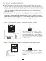
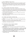
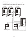
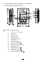
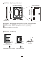
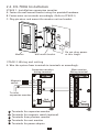
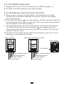
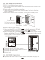
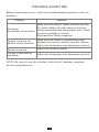
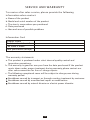
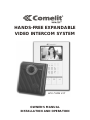
HANDS-FREE EXPANDABLE
VIDEO INTERCOM SYSTEM
HFX-700M KIT
,
OWNER S MANUAL
INSTALLATION AND OPERATION
TABLE OF CONTENTS
IMPORTANT SAFETY INSTRUCTIONS
WARNING
FCC CLASS B NOTICE
HFX-700M KIT VIDEO INTERCOM SYSTEM
1.HFX-700M KIT Introduction
2.HFX-700M KIT Parts Identification
2.1.Main Monitor
2.2.Door Camera
2.3.HFX-700M KIT Packaging
3.HFX-700M KIT Installation
3.1. Positioning the devices
3.2. Installation
3.3. Door Release Options
4. HFX-700M KIT Test after installation
4.1. Basic function test
4.2. Door release test(optional)
5. HFX-700M KIT Operation
5.1.Visitor Calls from Door Camera
5.2.Audio and Video monitoring
5.3.Unilateral voice mode control
EXPANSION OPTIONS
System Layout
Wiring Diagram
1. Expansion video monitor (EX-700H)
1.1.EX-700H Identification
1.2.EX-700H Installation
1.3.EX-700H Operation
1.3.1.Broadcast and intercom function
2. Expansion non-video monitor (EX-700A)
2.1.EX-700A Identification
2.2.EX-700A Installation
2.3.EX-700A Operation
2.3.1.Broadcast and intercom function
3.Door camera (EX-700D)
3.1.EX-700D Identification
3.2.EX-700D Installation
3.3.EX-700D Operation
TECHNICAL SPECIFICATIONS
TROUBLE SHOOTING
SERVICE AND WARRANTY
1
2
3
4
4
5
5
7
7
8
8
9
11
12
12
12
13
13
13
13
14
14
15
16
16
18
19
20
21
22
22
23
23
24
25
26
28
29
IMPORTANT SAFETY INSTRUCTIONS
WARING: TO REDUCE THE RISK OF FIRE OR ELECTRIC
SHOCK, DO NOT EXPOSE THE MONITOR OR POWER
ADAPTER TO WATER OR MOISTURE.
Read Instructions -All the safety and operating instructions should be
read before operating this equipment. These instructions should be
retained for future reference.
Heed Warnings - All warnings on the equipment and in the operating
instructions should be adhered to. All instructions regarding care and
operation of this equipment should be followed.
Power Sources - Equipment should only be connected to the power
supply specified in the operating instructions or as marked on the
equipment.
Power Cord Protection-Keep cable cords and plugs clear off other
objects, particularly at the point where they exit the equipment.
Cleaning - Clean the equipment by wiping with a soft cloth (do not use
any abrasive agents or water).
Non-use Periods - Power cords should be unplugged from the outlet
when left unused for a long period of time.
Object and Liquid Entry - Take care not to drop objects or liquids on
any part of the equipment.
Damage Requiring Service -The unit should be serviced by a qualified
service personnel when:
- The power supply cord or the plug has been damaged or
- Objects have fallen, or liquid has been spilled onto the equipment or
- The equipment has been exposed to rain or
- The equipment does not appear to operate normally or exhibits
a marked change in performance or
- The equipment has been dropped and/or the enclosure has been
damaged.
Servicing - Do not attempt to service the appliance beyond that
described in the operating instructions. All other servicing should be
referred to as Qualified Distributor's Service Personnel.
1
WARNING
WARNING: TO REDUCE THE RISK OF FIRE OR ELECTRIC
SHOCK, DO NOT EXPOSE THE MONITOR OR POWER
ADAPTER TO WATER OR MOISTURE.
CAUTION: DO NOT OPEN. RISK OF ELECTRICAL SHOCK.
CAUTION! TO REDUCE RISK OF ELECTRICAL SHOCK, DO NOT
REMOVE COVER OR BACK, NO USER SERVICEABLE PARTS
INSIDE, REFER SERVICING TO QUALIFIED SERVICE PERSONNEL.
OTHER WARNINGS
Monitor is designed for indoor use only. Do not install outdoors.
Keep the equipment dry. If water should get in,wipe off immediately.
Water contains minerals that can erode electronic circuits.
Intercom system is not operational during a power failure .
Intercom system may be affected by radio frequency interference or
EMI(electrical magnetic interference) in areas where broadcasting
station antennas are close by.
Keep all wiring at least 1 foot away from fluorescent lighting, dimmer
switches and AC power.
EXPLANATION OF TWO SYMBOLS
The lighting flash with arrowhead symbol, within an equilateral
triangle, is intended to alert the user to the presence of
uninsulated "dangerous voltage" within the product's enclosure
that may be of sufficient magnitude to constitute risk of
electrical shock to persons.
The exclamation point within an equilateral triangle is intended
to alert the user to the presence of important operating and
maintenance (servicing) instructions in the literature
accompanying the appliance.
2
FCC CLASS B NOTICE
NOTE:
This equipment has been Certified and found to comply with the limits
regulated by FCC,and CE. Therefore, it is designed to provide reasonable
protection against interference and will not cause interference with other
appliance usage. However, it is imperative that the user follows this
manuals guidelines to avoid improper usage which may result in damage
to the unit, electrical shock, and fire hazard or injury. In order to improve
the feature functions and quality of the product, the specifications are
subject to change without notice from time to time.
NOTE:
This equipment has been tested and found to comply with the limits for a
Class B digital device, pursuant to Part 15 of the FCC rules. These limits
are designed to provide reasonable protection against harmful
interference in a residential installation. This equipment generates uses
and can radiate radio frequency energy and, if not installed and used in
accordance with the instructions, may cause harmful interference with
radio communications. However, there is no guarantee that interference
will not occur in a particular installaition. If this equipment does cause
harmful interference to radio or televis ion reception, which can be
determined by turning the equipment off and on, the user is encouraged to
try to connect the interference by one or more of the following measures:
-
Reorient or relocate the monitor unit
Increase the separation between the monitor and camera
Connect the equipment on a separate outlet
Consult the dealer or an experienced radio or television technician
3
HFX-700M KIT VIDEO INTERCOM SYSTEM
1.Introduction
Thank you for purchasing the Hands-Free expandable Video Intercom
System HFX-700M.
This intercom system uses 2-wire installation, and operation is simple.
Allows you to identify and communicate with callers at the door, from the
security and convenience of any room in your home or office. Visitors
activate the system by pressing a call button on the outdoor camera,
which sounds a doorbell chime as well as turning on the inside video
monitor. A two-way intercom then lets you speak with visitors after first
visually identifying them.
It consists of a monitor station and an outdoor doorbell/camera unit.
This unit is capable of expanding up to a total of 4 indoor monitors and
2 door cameras. Expansion monitor can choose video(EX-700H) or
non-video(EX-700A).
For more information regarding the complete line of our products,
please visit www.comelitusa.com
4
2.HFX-700M KIT Parts Identification
2.1. Main Monitor
Main monitor
13
2
178mm
(7.0 )
15
12
2
5
6
36mm
(1.42 )
4
3
7
8
9
10 11
118mm
(4.65 )
HFX-700M Main monitor identification:
1.
2.
3.
4.
5.
6.
7.
8.
9.
10.
11.
12.
13.
14.
15.
16.
14
3.5" Color TFT Screen
Speaker
In use LED
Monitor LED
Intercom LED
Speaking out LED
Microphone
Cut-off button( )
Intercom button( )
Monitoring button( )
Door release button( )
Power switch
Brightness tuner( )
Sharpness tuner( )
Bell Volume tuner( )
Speaker Volume tuner( )
5
16
Main monitor wall mount bracket
Wall mount bracket
Wiring terminals
1
PT1
PT2
136mm
(5.35")
DG1
DG2
PT1
PT2
2
DG1
3
OUT+
4
DR2
5
DR1
OUT+
DG2
OUTDR2
DR1
<+>
POWER
<->
89mm
(3.5")
6
OUT-
<+>
POWER
<->
8.4mm(0.33")
1 Magnetic switch sensor connection: for door status detection
2 External chime or light indicator connection: for optional third party device
3 Expansion monitor connection: for more indoor monitor expansion
(w/polarity)
4 Door camera connection(2): to the 2nd door camera terminals(no polarity)
5 Door camera connection(1): to the 1st door camera terminals(no polarity)
6 Power adapter connection
6
2.2. Door Camera
1
7
2
3
130mm
(5.12")
JP2
1
4
5
2
10
JP1
9
8
3
4
11
6
36mm
(1.42")
98mm
(3.86")
HFX-700M Door Camera identification:
1.
2.
3.
4.
5.
6.
7.
8.
9.
10.
11.
White LED Illumination
1/3" Color CCD
Microphone
Speaker
Call button
Screw cover
CCD view angle knob
(-6 degrees, 0 degrees, 8 degrees, 16 degrees)
Jumper 2 (enable/disable light senor)
Jumper 1 (dry contact or current output selection)
Wire to door strike
Wire to main Monitor
2.3.HFX-700M KIT Packaging
PT1
PT2
DG1
HANDS-FREE EXPANDABLE
VIDEO INTERCOM SYSTEM
DG2
OUT+
OUTDR2
DR1
<+>
POWER
<->
X1
Wall mount bracket
X1
,
OWNER S MANUAL
INSTALLATION AND OPERATION
X1
Main monitor
Door camera
White wall
mount screws
X1
X4
Adaptor
X1
Manual
Flat head screws
X4
X1
Screws wrench
7
3. HFX-700M KIT Installation
3.1. Positioning the devices
Main monitor
Proper height:
Door camera
View Angle:
70cm
(27.6")
170cm
(66.9")
100cm
(39.3")
165cm
(64.9")
50cm(19.7")
50cm(19.7")
The proper height of monitor or door camera is 160~170cm(63"~67")
from the ground. This may vary on each installation. View range should
be actively tested before complete.
Viewing window of door camera is about 70cm up-n-down, and 100cm
left-n-right.
NOTE 1: Wiring distance
From main monitor to door camera:
Maximum of 50M with AWG22( 0.65mm) normal 2-wire parallel wires.
Maximum of 100M with AWG18( 1.0mm) normal 2-wrie parallel wires.
From monitor to monitor (every section):
Maximum of 100M with AWG22( 0.65mm) normal 2-wrie parallel wires.
NOTE 2: the installation environment
Narrow space may cause feedback
echo on speakerphone function.
Direct sunshine can cause blurry picture
on monitor.
Narrow space may cause feedback
echo on speakerphone function.
Too close to high power appliance may
cause audio/video interference.
8
3.2. Installation
STAGE 1: Installation main monitor
A. Fasten the wall mount bracket using the provided hardware.
B. Fasten wires on terminals accordingly. (Refer to STAGE 3)
C. Plug pin wires and mount the monitor unit on bracket.
PT1
PT2
DG1
DG2
OUT+
OUTDR2
DR1
<+>
POWER
<->
Monitor
Wall mount bracket
Do not plug power
at this stage.
STAGE 2: Installation door camera
A. Use screws wrench disassemble screw and remove door camera unit
from bracket.
B. Fasten wall mount bracket on position.
C. Fasten wires on terminals and select jumpers for desire function.
(refer to STAGE 3)
D. Mount door camera unit on bracket, secure the assembly screw.
Screws wrench
Pull out screw cover
to access the screw
Door camera
9
Bracket
STAGE 3: Wiring and setting
A. Wire the system from terminals to terminals as accordingly.
B. Select and plug JP2 to its RIGHT(
) to disable automatic LED light
supplement at night. Factory setting is LEFT(
) as enable.
C. Select and plug JP1 to its RIGHT(
) for direct current output control.
Factory setting has JP1 to its LEFT(
) for dry contact bridge control.
(Refer to 3.3 Door Release Options)
Main monitor
Wiring terminal
door camera
Wiring terminal
Magnetic switch(optional)
External chime(optional)
8
9
1
2
JP1
To expansion monitor
7
JP2
3
PT1
PT2
DG1
DG2
OUT+
OUT-
4
To the 2nd door camera
5
6
7
8
9
3
4
DR1
5
Terminals for magnetic switch (optional)
Terminals for external chime (optional)
Terminals for expansion monitor (w/polarity)
Terminals for the 2nd door camera (w/o no polarity)
Terminals for the 1st door camera (w/o no polarity)
Terminals for power adapter
Terminals to main monitor (w/o no polarity)
Terminals for door strike
Electric Lock
10
2
DR2
<+>
POWER
<->
1
2
3
4
1
Red 6
Black
3.3. Door Release Options
Each Door Camera on the system is able to operate and release one
electric lock. On a full system with 2 door cameras, the user is able to
release up to two electric locks. The system can only release one electric
lock at a time, depending on which door camera the call originated from.
There are two door release wiring options that work with the Video
Intercom System.
The system can either provide a normally open dry contact (figure 1), or
can be configured to give power (12V DC 300mA) straight to an electric
lock that is within the power requirements (figure 2). If you are using
power from the system (figure 2), It is necessary to use an electric lock
that requires less than 300mA of power to engage the strike.
Figure 1: Door Release Option 1 (Additional power supply)
Door camera
JP1
Electric Lock
Power for Lock
12/24V DC
1 Amp Max
NOTE: When jumper setting is left
(factory setting), the DOOR RELEASE
terminals provide as a normal open
dry contact with no polarity, allowing
maximum by-pass current of AC24V
or DC24V 1A.
Figure 2: Door Release Option 2 (Using power from the system)
7
JP2
1
2
JP1
JP1
3
4
Door camera
Electric Lock
NOTE: When jumper setting is right,
the DOOR RELEASE terminals provide
current output of maximum 12VDC
300mA.
11
4. HFX-700M KIT Test after installation
Installed and with a good line, the need to test the system.
4.1. Basic function test
A. Plug in the power supply.
B. Press the call button on the door camera.
C. Check and adjust doorbell volume.
D. Check and adjust the picture quality.
E. Listen to the door camera and adjust the speaker volume.
F. Adjust view angle of the door camera.
4.2. Door release test(optional)
A. For door strike installation instructions please refer to page 11.
B. If there is an electric strike installed, activate the monitor by pressing
the call button from the door camera.
C. Once the unit is activated, press and hold the door release button
and open the door.
D. If the strike is operational, it should release the door when the button is
pressed.
E. This is a DC powered strike, so it will trigger, and open the strike for as
long as you are holding the button.
Main monitor
Door camera
Brightness tuner
Sharpness tuner
Bell Volume tuner
Speaker Volume tuner
Call button
Door release button
Monitoring button
Intercom button
Cut-off button
12
5. HFX-700M KIT Operation
Operating the video intercom system consists of responding to visitor
calls from door camera, releasing a door strike from indoor monitor;
audio and video monitoring from any indoor monitor; voice broadcast
from one monitor to all others; engage intercom function after voice
broadcast.
5.1. Visitor Calls from Door Camera
A. When the Call button on the camera is pressed, All monitors on the
system will ring with a chime sound and all monitors will be activated.
B. After the call, if nothing on the monitor is pressed, the system will time
out after 30 seconds. If the monitor button
is pressed, the system
will stay active for 90 seconds.
C. You are able to terminate the activity on the monitor at any time by
pressing the Cut-off button
.
D. Press door release button
from monitor can release remote door
strike at door camera.
5.2. Audio and Video monitoring
A. Press the monitor button
can monitor audio and video from door
camera.
B. If there is a second door camera on this system, press Monitor button
again to scroll to the second expansion door camera.
C. At anytime if you wish to terminate the monitoring, press the Cut-off
button
to terminate the system.
5.3. Unilateral voice mode control
(similar to walky-talky)
A. Speaking out LED on means voice is free to go out from monitor to
door camera.
B. During conversation, press Monitor Button
for 2 seconds can switch
to unilateral voice mode. Under this mode, press-on Monitor Button
and speaking out LED on allows unilateral voice to go out to door
camera; let-go Monitor Button
and speaking out LED off allows
unilateral voice to come in from door camera.
C. This function can be useful when environment at door camera side
becomes too noisy.
13
EXPANSION OPTIONS
A. HFX-700M package consists a main monitor, a door camera, and a
power adaptor for the monitor.
B. With HFX-700M KIT as a basic, the system is capable of expanding up
to a total of 4 indoor monitors and 2 door cameras. Expansion monitor
can choose video(EX-700H) or non-video(EX-700A).
System layout 1:
NOTE: the system is capable of expanding up to a total of 4 monitors
(1 main video monitor + 3 expansion video monitor) and 2 door cameras.
EX-700D
EX-700H
HFX-700M KIT
EX-700H
EX-700H
System layout 2:
NOTE: the system is capable of expanding up to a total of 4 monitors
(1 main video monitor + 3 expansion non-video monitor) and 2 door
cameras.
EX-700D
EX-700A
HFX-700M KIT
14
EX-700A
EX-700A
Wiring Diagram:
A. Magnetic switch or external bell chime wiring, refer to page 10.
B. Electric lock strike wiring, refer to page 11.
C. Expansion video or non-video monitor wiring diagram is the same.
EX-700H
or EX-700A
Wiring terminal
EX-700H
or EX-700A
Wiring terminal
EX-700H
or EX-700A
Wiring terminal
PT1
PT1
PT1
PT2
PT2
PT2
OUT+
OUT+
OUT+
OUT-
OUT-
OUT-
IN+
IN+
IN+
IN-
IN-
IN-
<+>
POWER
<->
Red
Black
<+>
POWER
<->
Red
Black
Red
Black
<+>
POWER
<->
PT1
PT2
DG1
DG2
OUT+
OUTDR2
DR1
<+>
POWER
<->
JP2
1
2
JP1
JP2
3
4
The 2nd door camera
EX-700D Wiring terminal
1
2
JP1
3
4
The 1st door camera
Wiring terminal
15
Red
Black
Main monitor
Wiring terminal
HFX-700M Kit
1. Expansion Video Monitor (EX-700H)
1.1. EX-700H Identification
EX-700H
13
1
178mm
(7.0 )
15
12
2
5
6
36mm
(1.42 )
4
3
7
8
9
10 11
118mm
(4.65 )
EX-700H identification:
1.
2.
3.
4.
5.
6.
7.
8.
9.
10.
11.
12.
13.
14.
15.
16.
14
3.5" Color TFT Screen
Speaker
In use LED
Monitor LED
Intercom LED
Speaking out LED
Microphone
Cut-off button( )
Intercom button( )
Monitoring button( )
Door release button( )
Power switch
Brightness tuner( )
Sharpness tuner( )
Bell Volume tuner( )
Speaker Volume tuner( )
16
16
EX-700H Wall mount bracket
Wiring terminals
Wall mount bracket
1
PT1
PT1
PT2
PT2
136mm
(5.35 )
OUT+
2
OUTIN+
IN-
3
<+>
POWER
<->
4
89mm
(3.5 )
OUT+
OUTIN+
IN-
<+>
POWER
<->
8.4mm(0.33 )
1 Magnetic switch sensor connection: for door status detection
2 OUT: to next EX-700H monitor, w/polarity
3 IN: from HFX-700M or EX-700H monitor, w/polarity
4 Power adapter connection
EX-700H packaging
PT1
PT2
OUT+
OUTIN+
IN-
<+>
POWER
<->
Expansion monitor
X1
X1
X1
Wall mount bracket
X2
White wall mount screws
X2
Flat head screws
17
Adaptor
1.2. EX-700H Installation
STAGE 1: Installation expansion monitor
A. Fasten the wall mount bracket using the provided hardware.
B. Fasten wires on terminals accordingly. (Refer to STAGE 2)
C. Plug pin wires and mount the monitor unit on bracket.
PT1
PT2
OUT+
OUTIN+
IN-
<+>
POWER
<->
Monitor
Wall mount bracket
Do not plug power
at this stage.
STAGE 2: Wiring and setting
A. Wire the system from terminals to terminals as accordingly.
Expansion monitor
wiring terminal
Main monitor
Wiring terminal
PT1
PT1
Magnetic
switch
PT2
PT2
2
DG1
OUT+
4
DG2
OUTIN+
To next
expansion monitor
OUT+
3
OUT-
1
INDR2
DR1
<+>
POWER
<->
1 Terminals
2 Terminals
3 Terminals
4 Terminals
5 Terminals
Red 5
Black
for expansion monitor
for magnetic switch (optional)
from previous monitor
for next monitor
for power adapter
18
<+>
POWER
<->
Red
Black
1.3. EX-700H Operation
Operates the same as the main monitor unit (Refer to page 13).
1.3.1.Broadcast and intercom function
A. When system consists of main monitor and expansion monitor and an
outdoor doorbell/camera unit, system can provide intercom function.
B. Press intercom button
from any monitor, all other monitors will react
by making bell sound. At the same time, host can speak and broadcast
voice message to all other monitors.
C. The broadcast mode can last for 20 seconds. During the 20 seconds,
any other monitor press intercom button
can engage intercom
conversation with the host for maximum of 90 seconds. This function
provides intercom only, monitors show no picture.
D. At anytime if you wish to terminate the monitoring, press the Cut-off
button
to terminate the system.
Main monitor
Expansion monitor
Door camera
Call button
Door release button
Monitoring button
Intercom button
Cut-off button
Door release button
Monitoring button
Intercom button
Cut-off button
19
2. Expansion Non-video Monitor (EX-700A)
2.1. EX-700A Identification
12
13
178mm
(7.0 )
14
11
1
4
5
36mm
(1.42 )
3
2
6
7
8
9
118mm
(4.65 )
EX-700A identification:
1.
2.
3.
4.
5.
6.
7.
8.
9.
10.
11.
12.
13.
14.
15.
Speaker
In use LED
Monitor LED
Intercom LED
Speaking out LED
Microphone
Cut-off button( )
Intercom button( )
Monitoring button( )
Door release button( )
Power switch
Brightness tuner( )
Sharpness tuner( )
Bell Volume tuner( )
Speaker Volume tuner( )
20
10
15
EX-700A Wall mount bracket
Wiring terminals
Wall mount bracket
1
PT1
PT1
PT2
PT2
136mm
(5.35 )
OUT+
2
OUTIN+
IN-
3
<+>
POWER
<->
4
89mm
(3.5 )
OUT+
OUTIN+
IN-
<+>
POWER
<->
8.4mm(0.33 )
1 Magnetic switch sensor connection: for door status detection
2 OUT: to next EX-700A non-video monitor, w/polarity
3 IN: from HFX-700M or EX-700A monitor, w/polarity
4 Power adapter connection
EX-700A packaging
PT1
PT2
OUT+
OUTIN+
IN-
<+>
POWER
<->
Expansion
non-video monitor
X1
X1
X1
Wall mount bracket
X2
White wall mount screws
X2
Flat head screws
21
Adaptor
2.2. EX-700A Installation
STAGE 1: Installation expansion monitor
A. Fasten the wall mount bracket using the provided hardware.
B. Fasten wires on terminals accordingly. (Refer to STAGE 2)
C. Plug pin wires and mount the monitor unit on bracket.
PT1
PT2
OUT+
OUTIN+
IN-
<+>
POWER
<->
Monitor
Wall mount bracket
Do not plug power
at this stage.
STAGE 2: Wiring and setting
A. Wire the system from terminals to terminals as accordingly.
Expansion monitor
wiring terminal
Main monitor
Wiring terminal
PT1
PT1
Magnetic
switch
PT2
PT2
2
DG1
OUT+
4
DG2
OUTIN+
To next
expansion monitor
OUT+
3
OUT-
1
INDR2
DR1
<+>
POWER
<->
1 Terminals
2 Terminals
3 Terminals
4 Terminals
5 Terminals
Red 5
Black
for expansion monitor
for magnetic switch (optional)
from previous monitor
for next monitor
for power adapter
22
<+>
POWER
<->
Red
Black
2.3. EX-700HA Operation
A. Operates the same as the main monitor unit (Refer to page 13).
B. EX-700A only audio function, not video function.
2.3.1.Broadcast and intercom function
A. When system consists of main monitor and expansion non-video
monitor and an outdoor doorbell/camera unit, system can provide
intercom function.
B. Press intercom button
from any monitor, all other monitors will react
by making bell sound. At the same time, host can speak and broadcast
voice message to all other monitors.
C. The broadcast mode can last for 20 seconds. During the 20 seconds,
any other monitor press intercom button
can engage intercom
conversation with the host for maximum of 90 seconds. This function
provides intercom only.
D. At anytime if you wish to terminate the monitoring, press the Cut-off
button
to terminate the system.
Main monitor
Expansion non-video monitor
Door camera
Call button
Door release button
Monitoring button
Intercom button
Cut-off button
Door release button
Monitoring button
Intercom button
Cut-off button
23
3. Door Camera (EX-700D)
3.1. EX-700D Identification
1
7
2
3
130mm
(5.12")
JP2
1
4
5
2
10
JP1
9
8
3
4
11
6
36mm
(1.42")
98mm
(3.86")
EX-700D identification:
1.
2.
3.
4.
5.
6.
7.
8.
9.
10.
11.
White LED Illumination
1/3" Color CCD
Microphone
Speaker
Call button
Screw cover
CCD view angle knob
(-6 degrees, 0 degrees, 8 degrees, 16 degrees)
Jumper 2 (enable/disable light senor)
Jumper 1 (dry contact or current output selection)
Wire to door strike
Wire to main Monitor
EX-700D packaging
X1
Door Camera
X2
X2
White wall
mount screws
Flat head screws
24
X1
Screws wrench
3.2. EX-700D Installation
STAGE 1: Installation door camera
A. Use screws wrench disassemble screw and remove door camera unit
from bracket.
B. Fasten wall mount bracket on position.
C. Fasten wires on terminals and select jumpers for desire function.
(refer to STAGE 2)
D. Mount door camera unit on bracket, secure the assembly screw.
Screws wrench
Pull out screw cover
to access the screw
Door camera
Bracket
STAGE 2: Wiring and setting
A. Select and plug JP2 to its RIGHT(
) to disable automatic LED light
supplement at night. Factory setting is LEFT(
) as enable.
B. Select and plug JP1 to its RIGHT(
) for direct current output control.
Factory setting has JP1 to its LEFT(
) for dry contact bridge control.
(Refer to Page 11Door Release Options)
EX-700D wiring terminal
PT1
PT2
DG1
3
4
2
JP2
DG2
OUT+
1
2
JP1
3
4
OUTDR2
1
DR1
1
2
3
4
Terminals for EX-700D door camera
Terminals for main monitor DR2 terminals
Terminals for door strike
Electric Lock
<+>
POWER
<->
Red
Black
Main monitor
wiring terminal
3.3. EX-700D Operation
Operates the same as the 1st door camera unit (Refer to page 13).
25
TECHNICAL SPECIFICATIONS
HFX-700M(main monitor)
3.5" digital TFT-LCD
320 x 240 pixels
30 seconds time out;
90 seconds for conversation
Auto Timer (intercom):
20 seconds time out;
90 seconds for conversation
Operating Temperature: 14 F ~ 140 F, indoor
Dimensions (w/ bracket): 4.65"(L) x 7.0"(W) x 1.42"(D)
Power adaptor:
input 100~240VAC 50/60Hz;
output 23VDC/1A(24W),
external
Power consumption:
standby 2.1W, operating 7.8W
(maximum)
Display:
Resolution:
Auto Timer (visitor call):
HFX-700M(door camera)
Image Sensor:
Resolution:
Camera Lens:
View Angle:
Auto Light Sensor:
Operating Temperature:
Dimensions (w/ bracket):
Power consumption:
Remote Control:
(dry contact bridge)
Remote Control:
(direct current output)
26
1/3" Sharp CCD
250,000 pixels (NTSC)
F/NO: 2.0 (120 degree)
-6 ,0 ,8 ,16 manually adjustable
enable/disable selectable (JP1)
-13 F ~ 140 F, outdoor
3.86"(L) x 5.12"(W) x 1.42"(D)
powered by main monitor
for maximum by pass current
of 24V/1A
maximum of DC12V/300mA
EX-700H(optional expansion monitor)
Display:
Resolution:
Auto Timer (visitor call):
3.5" digital TFT-LCD
320 x 240 pixels
30 seconds time out;
90 seconds for conversation
Auto Timer (intercom):
20 seconds time out;
90 seconds for conversation
Operating Temperature: 14 F ~ 140 F, indoor
Dimensions (w/ bracket): 4.65"(L) x 7.0"(W) x 1.42"(D)
Power adaptor:
input 100~240VAC 50/60Hz;
output 23VDC/1A(24W),
external
Power consumption:
standby 1.4W, operating 3.0W
(maximum)
EX-700A(optional expansion non-video monitor)
Auto Timer (visitor call):
30 seconds time out;
90 seconds for conversation
Auto Timer (intercom):
20 seconds time out;
90 seconds for conversation
Operating Temperature: 14 F ~ 140 F, indoor
Dimensions (w/ bracket): 4.65"(L) x 7.0"(W) x 1.42"(D)
Power adaptor:
input 100~240VAC 50/60Hz;
output 23VDC/1A(24W),
external
Power consumption:
standby 1.4W, operating 3.0W
(maximum)
EX-700D(optional door camera)
Image Sensor:
Resolution:
Camera Lens:
View Angle:
Auto Light Sensor:
Operating Temperature:
Dimensions (w/ bracket):
Power consumption:
Remote Control:
(dry contact bridge)
Remote Control:
(direct current output)
27
1/3" Sharp CCD
250,000 pixels (NTSC)
F/NO: 2.0 (120 degree)
-6 ,0 ,8 ,16 manually adjustable
enable/disable selectable (JP1)
-13 F ~ 140 F, outdoor
3.86"(L) x 5.12"(W) x 1.42"(D)
powered by main monitor
for maximum by pass current
of 24V/1A
maximum of DC12V/300mA
TROUBLE SHOOTING
Before requesting service, check the troubleshooting quide to solve the
problem.
Problem
Solution
No power
(no picture on monitor)
Make sure AC plug is firmly inserted into the
AC outlet. Make sure the power terminal is
firmly connected into the monitor unit. Check
to ensure polarity is correct.
(Red=positive, Black=negative).
System is on but no
picture on the monitor
Make sure the cable is cnnected securely
between the master monitor and the camera.
Adjust the brightness and sharpness controls.
Sound is too low
Adjust the volume control.
Picture is too dark or
too white
Adjust the brightness and sharpness controls
NOTE: Be sure to use this product with the AC adapter supplied
by the manufacturer.
28
SERVICE AND WARRANTY
To receive after sales service, please provide the following
information when contact.
a. Name of the product
b. Model and serial number of the product
,
c. The store s name where you purchased
d. Date purchased
e. Idea and area of possible problems
Information Card
Product name
Model and serial number
,
The store s name
Date purchased (receipt)
The warranty statements
a. This product is produced under strict internal quality control and
inspection procedures.
b. The warranty is good for one year from the date purchased.If the product
reacts down under proper treatment during warranty,please contact our
after sales connection for free-of -charge repairs.
c. The following exceptional cases will be subject to charge,even during
warranty period.
Breakdown caused by transport,or through careless treatment by customer.
Breakdown caused by unauthorized repair or modification.
Breakdown caused by natural disaster or electric power disorder.
29
http:// www.comelitusa.com
[email protected]