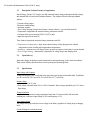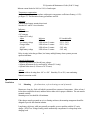
1
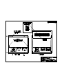
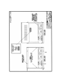
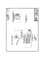
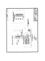
FC Operation & Maintenance Guide (20 & 25 Amp)
FC/FCA
20 & 25 AMPERE OUTPUT
BATTERY CHARGER
OPERATION & MAINTENANCE GUIDE
SENS part no.:
Document revision:
DCN No.
Date
101117
1.9
104041
9/30/02
1840 Industrial Circle,
Longmont, CO 80501
Fax: (303) 678-7504
Tel: (303) 678-7500
Installation or Service problems? Call SENS at (800) 742-2326
between 8:00 A.M. and 5:00 P.M. Mountain time Monday through Friday.
FC Operation & Maintenance Guide (20 & 25 Amp)
IMPORTANT SAFETY INSTRUCTIONS
SAVE THESE INSTRUCTIONS
This manual contains important safety and operating instructions for Stored Energy Systems
(SENS) model battery charger model FC.
Before using the battery charger, read all instructions and cautionary markings on the battery charger,
battery and equipment connected to the battery system.
Before You
Begin
Particular attention should be paid to three types of notices throughout this guide. These are as
follows:
WARNING: is used in this manual to warn of possible personal or property injury
CAUTION: is used in this manual to warn of possible equipment damage
NOTE: is used in this manual to provide advice on how to obtain maximum performance,
reliability or life from components of your system.
WARNING:
Please read
these safety
warnings and
heed them.
Failure to do so
could result in
either severe
personal injury
or equipment
damage.
To reduce the risk of injury, charge only properly sized lead-acid or nickel cadmium batteries. Other
types of batteries or under-sized batteries may burst causing personal injury and damage.
• Do not install or operate charger if it has been dropped or otherwise damaged. Return it to the
factory for repair.
• Install the charger in accordance with all local codes.
• Do not expose charger to rain or snow.
• Do not disassemble charger; return to factory when service or repair is required. Incorrect
assembly may result in a risk of electric shock or fire.
• To reduce risk of electric shock, de-energize and disconnect the AC input and the battery from the
charger before attempting maintenance or cleaning.
• Use of an accessory not recommended or sold by SENS may result in a risk of fire, electric shock
or personal injury.
• During normal operation, batteries may produce explosive hydrogen gas. Never smoke, use an
open flame, or create sparks near the battery or charger.
2
FC Operation & Maintenance Guide (20 & 25 Amp)
• Remove jewelry, watches, rings, etc. before installing battery or charger.
1
READ THIS
FIRST
CAUTION: Failure to follow installation instructions may cause equipment
damage, or void the equipment warranty. READ THESE INSTRUCTIONS
BEFORE PROCEEDING!
• The charger must be connected to a battery for it to operate properly (see Section 4.1). If
the charger is feeding a load and charging a battery, disconnecting the battery will cause the
output voltage to rise to unsafe levels with possible damage to connected loads. Always
disconnect the AC mains power before disconnecting the battery from the charger. If
the charger is not connected to a battery it will operate at approximately half its rated
voltage, and the alarm relays (if the unit is so equipped) will chatter.
• Do not connect the battery leads to the charger backwards. Doing so will blow the output
fuse when the charger is energized
• Changing factory-set potentiometers voids the warranty. Contact the factory if the settings
on your charger are incorrect.
Before determining that the charger is not working correctly, check the following:
1. Is AC power available to the charger?
2. Are any fuses blown?
3. Is the charger connected to a battery of the correct voltage?
4. Was the charger damaged in transit or installation?
5. If you determine that the charger is not working because it is not putting out any current,
check the battery’s state of charge. If the battery is fully charged it is perfectly normal for
the charger to indicate zero current flow. See Figure 4.1.
6. If the battery is being over- or undercharged, check whether the output voltage settings have
been tampered with. The pots should be covered with either white adhesive paper dots or
a hard red varnish.
2
Overview
This manual covers installation, operation and troubleshooting of 20 & 25 amp SENS battery
chargers type FC and FCA. Complete parts lists and board-level documentation is not
included; these are available separately from SENS.
Please follow the installation and use instructions. They are vital to the satisfactory operation of
the charger. Service information is provided for the benefit of customers experienced in the
service of power conversion equipment. If there are any doubts about adjusting, maintaining or
servicing the equipment, return the charger to the factory for adjustment/repair.
3
FC Operation & Maintenance Guide (20 & 25 Amp)
2.1
Description, Product Features & Application
Stored Energy Systems’ FC chargers are fully automatic battery chargers that automatically recharge
and maintain lead-acid and nickel-cadmium batteries. The chargers offer the following standard
features:
• Constant voltage output
• Electronic current limiting
• Automatic equalize
• True Voltage Sensing (charger senses battery voltage at battery - no extra leads needed)
• Temperature compensation to maximize battery performance and life
• Complete alarm system meeting NFPA 110 (FCA only)
• Input and output circuit breakers
Three features in particular maximize battery performance and life:
• Temperature Compensation - helps ensure that the battery is fully charged at low ambient
temperatures but not overcharged at high ambient temperatures.
• Autoboost - automatic two-rate charge feature operates in response to the battery's current demand
• True Voltage Sensing - automatically compensates for voltage drop in the charging leads
2.2
Upon Delivery
Inspect the charger for damage caused during transit, and report damage to the carrier immediately.
Then contact SENS to determine how best to repair/replace the damaged unit.
2.3
Specifications
Input voltage and frequency
Voltage and frequency are as indicated in the part number and on the serial number label: Possibilities
are 120 volt 60 Hz, 230 volt 60 Hz, 230 volt 50 Hz or 277 volt 60 Hz.
Output voltage
• Standard 12, 24 & 32 volts
• Float voltage adjustable from 90% to 120% of nominal. Boost voltage adjustable up to 15% above
float voltage
Voltage regulation
Temperature-compensated voltage regulation is better than 1% from no load to full load with
simultaneous variations in input voltage of 10% and frequency of 5%
True voltage sensing
The charger always provides the correct voltage to the battery regardless of voltage drop in charging
leads
Current limiting & overload protection
FC Operation & Maintenance Guide (20 & 25 Amp)
Inherent current limited at 100% to 110% of rated output
Temperature compensation
Output voltage changes in accordance with negative temperature coefficient of battery (-0.12%
per degree F). This maximizes battery performance and life.
Protection
Current limited output; sustains short circuit
Standard AC and DC circuit breakers
Indicators
• DC voltmeter
• DC ammeter
• Alarms (FCA only):
Alarm
AC on
Low battery voltage
Charger failure
AC fail
High battery voltage
Indicator
LED
LED & form C contact
LED & form C contact
LED & form C contact
LED & form C contact
FCA model suffix
-2231, -2431
-2231, -2431
-2431 only
-2431 only
Delay circuitry in the charger failure, low battery and high battery alarm systems prevents
spurious indications
Controls & adjustments
• Separate adjustments for float & boost voltages
• Separate adjustments for low and high DC alarms (FCA only)
• Optional boost timer (0-24 hours or 0-72 hours)
Ambient
Operates without de-rating from -10C to +50C. Humidity 5% to 95%, non-condensing.
Natural convection cooled.
3
Installation
3.1
Mounting
(for dimensions, refer to drawings at end of manual)
Mount on a clean, dry, fixed wall which is protected from extremes of temperature. Allow at least 6
inches above and below the unit, and three inches either side for proper ventilation. The unit must be
mounted vertically.
Mounting screw size should be #10 minimum.
If the charger must be mounted on or in a vibrating enclosure, the mounting arrangement should be
designed to provide full vibration isolation.
Long battery cable runs, while not generally acceptable, are not a problem with the FC series
charger. SENS True Voltage Sensing circuit automatically compensates for voltage drop in the
charging leads.
5
FC Operation & Maintenance Guide (20 & 25 Amp)
Protect the charger from construction grit, metal chips, paint or other debris. Clean away debris after
installation.
3.2
Power Connections
Connection should be made by a qualified installer. Remove the two screws securing the charger's
top front panel to gain access to the connections.
Use AWG #8 or larger wire for DC (charger to battery) leads.
Use AWG #12 or larger wire for AC input and ground connections.
WARNING: The battery charger should be connected to a grounded permanent wiring system. A
ground stud is provided for this purpose
Knockouts accommodating 1/2" conduit and fittings are located on each side of the charger. Run the
AC wiring independent of the DC and alarm wiring.
The voltmeter will show battery voltage as soon as the FC connection is completed. Check the
voltmeter as soon as the FC connection has been made. If the meter reads zero or is deflecting
below zero, reverse the polarity of the battery connections. The charger will be damaged if it is
operated into a backwards connected battery.
3.3
Alarm Connections (pertains only to FCA models)
Refer to the alarm installation drawings at the end of this manual for connection instructions..
Alarm relays are rated for a maximum of 2 amps at 24 volts DC, or 0.5 amps at 32 volts DC (noninductive loads only). Connect the alarm relay to customer-supplied supervisory system only -- do
not apply AC power to the relays and do not exceed the relays’ ratings.
There are two versions of FCA alarm board; both meet NFPA 110:
Condition
LED Indicator
Form C contact with Model # suffix
AC on
Low battery voltage
Charger failure
AC fail
High battery voltage
Green LED
Amber LED
Red LED
Red LED
Red LED
none
-2231, -2431
-2231, -2431
-2431 only
-2431 only
4
Using Charger
4.1
Charger Features
FC/FCA chargers feature soft start circuitry which causes a gradual increase in output power
after application of AC power. The Autoboost system causes the charger initially to operate at
6
FC Operation & Maintenance Guide (20 & 25 Amp)
the high rate. When the charger reaches the boost voltage set point, and current has dropped
to between 50% to 70% of the charger's rating, the charger will revert to the float mode.
The transition from boost to float will result in the battery drawing no current from the charger.
Once the battery voltage nears the float setting, the charger will again deliver a small amount of
current to the battery to maintain the battery at its fully charged state. Figure 4 is a graph of
how the Autoboost system works.
The battery charger is temperature compensated to match the negative temperature
coefficient of the battery. Thus the float voltage will increase slightly as the temperature
decreases, and decrease as temperature increases. The battery charger is electronically current
limited to 110% of rated output. The charger will decrease its current output when the battery
voltage is lower than nominal.
FIGURE 4
Boost voltage
Float voltage
Battery voltage
Point at which charger changes
from current limit to voltage limit
Volts
Point at which AUTOBOOST
returns charger to float voltage
100% charger
output current
Charger output current
Amps
50% to 75% of
charger current limit
Zero current flow
0
Time
NOTE:
When the charger switches from BOOST to FLOAT mode,
no current will flow into the battery for a while due to the battery's
high state of charge. This is completely normal, and indicates
that the charger is working properly.
4.2 Ammeter and Voltmeter
The voltmeter and ammeter (and alarm LEDs on the FCA models) provide indication of
normal operation. Correct operation is indicated when the voltmeter reads 110% to 120% of
nominal battery voltage. High current flow indicates that the battery has been discharged, and
is being recharged. Low current flow normally indicates that the battery is fully charged. The
charger will at times read 0 amps. This most commonly happens after the charger has reverted
7
FC Operation & Maintenance Guide (20 & 25 Amp)
from the boost (or high rate) charge to float charge. Do not automatically assume that the
charger has failed if the ammeter reads 0 amps!
4.3
Alarm Operation (pertains only to FCA models)
The alarm LEDs have the following meanings:
Power on:
AC power is available to the charger
Charge fail:
The charger senses voltage rather than current to detect "failure"; once battery
voltage drops approximately 1 volt below nominal the alarm activates. This may
occur when:
a) The battery is fully discharged
b) The AC power has failed, and the battery has become discharged
c) There is an excessive load on the charger (not a charger failure)
d) The charger has failed
There is a time delay of approximately one minute between the start of the alarm
condition and the actual alarm signal. This prevents spurious indications during
short-term deep battery discharge (as would happen during engine cranking). The
delay period can be adjusted. See section.5.3
AC fail
There is no AC power to the charger. This indicates either:
a) The AC power has failed
b) The input fuse is blown
High battery:
Indicates that the output voltage is above a preset, adjustable point. The control
circuit may have malfunctioned, or it could be misadjusted. In some cases, long
leads of small gauge wire to the batteries cause a high battery alarm. The charger's
True Voltage Sensing circuit automatically compensates for voltage drop in the
charging leads. If charging leads are too small, the charger will operate at a high
voltage to overcome high resistance in the leads. The alarm indication is made as
soon as the alarm condition begins and lasts for approximately one minute after the
alarm condition ends.
Low battery:
Indication is made when the battery voltage is below a preset, adjustable point.
This may occur when:
a) The AC power has failed and the battery has become discharged
b) The charger has malfunctioned
c) The battery is defective
There is a delay of approximately one minute between the start of the alarm
condition and the alarm signal. This prevents false indications due to engine
cranking or other temporary deep battery discharge. The delay period can
be adjusted. Consult the factory.
8
FC Operation & Maintenance Guide (20 & 25 Amp)
The FCA's alarm system includes a Form C contacts. The contacts change position whenever
the associated alarm is activated.
5
Adjustments
Customer service of the charger is recommended only if the technician is experienced in electrical
and electronic equipment. If a trained technician is not available, return the charger to the factory
for adjustment.
Instructions for charger adjustment are found on the following pages.
5.1 Adjusting the Charger Output Voltage
NOTE: There are two ways to adjust the charger voltage. The first method requires only an external
precision voltmeter. The second method takes less time, but requires a 40 volt, 100,000 micro farad
capacitor and an adjustable load.
NOTE: The charger can not be correctly adjusted without either a battery or the capacitor mentioned
above. SENS’ True Voltage Sensing circuit senses battery voltage only between charging current
pulses. The charger will provide its correct voltage only when a battery is connected.
All chargers (adjustment procedure where capacitor and & load bank are not available)
Use an external precision voltmeter connected to either the battery or the charger output terminals.
Make all adjustments in small increments to allow the battery voltage level to react to the new setting.
The adjustments must be made while the battery is connected to the charger, so some patience will be
required.
1. Open lower front panel to gain access to control circuit. The top cover hinges upward, the lower
cover hinges downward.
2. Remove protective paper dots from potentiometers labeled FLOAT and BOOST.
3. Turn boost voltage pot fully counter clockwise.
4. Adjust float pot in small increments until the battery reaches the desired voltage. The current output
should be in the range of 1 to 2 amps. As it takes the battery time to react to voltage changes, some
patience will be required.
5. Turn the boost pot fully clockwise (maximum output voltage).
Now adjust the boost charge voltage as described below:
Different adjustment procedures are used for AUTOBOOST and timed boost chargers.
AUTOBOOST chargers only (not equipped with a timer)
9
FC Operation & Maintenance Guide (20 & 25 Amp)
6. Put the charger in the AUTOBOOST mode by partially discharging the battery, then removing
and restoring the charger's AC power source.
7. Allow the battery voltage to rise to the desired high rate charge level. Once at this voltage,
carefully turn the boost pot counter-clockwise until the charger ammeter suddenly drops to
approximately zero amps.
8. Charger is now adjusted. Replace paper dots and close front cover.
Chargers with timed boost
6. Turn timer knob to start high rate charging.
7. Allow the battery voltage to rise to the desired high rate charge level. The battery should be
discharged so that charger is producing between 60% and 100% of its rated current. Once at
the desired boost voltage, carefully turn the boost pot counter-clockwise until the charger
ammeter drops noticeably (to between 1/2 and 2 amps).
8. Charger is now adjusted. Replace paper dots and close front cover.
Alternative adjustment procedure using capacitor and load bank -- all chargers
The capacitor and adjustable load take the place of a battery, so you do not have to wait for
the battery voltage to increase or decrease to new output voltage levels. The time delays in the alarm
circuit, however, cannot be defeated.
Connect the capacitor in parallel with the output terminals, making sure that the polarity is
correct. Use the same general adjustment procedure as the "all chargers" section above;
setting changes, however, do not have to be made in small increments. For the float
adjustment, adjust the load bank so that the charger puts out about one amp. For the boost
adjustment, adjust the load bank so that the charger puts out about 80% of its rated current.
This high load causes AUTOBOOST chargers to switch to high rate charge.
5.2
Factory-Set Output Voltages
Chargers set for lead-acid battery
12 volt
24 volt
32 volt
Float voltage
13.3
26.6
35.5
Boost voltage
14.0
28.0
37.3
12 volt
24 volt
32 volt
Float (# cells), voltage
(10) 14.3
(19) 27.2
(20) 28.6
(25) 35.8
(27) 38.6
Boost (# cells), voltage
(10) 15.2
(19) 28.6
(20) 30.0
(25) 37.5
(27) 40.5
Chargers set for nickel cadmium battery
10
FC Operation & Maintenance Guide (20 & 25 Amp)
5.3
Adjusting Alarm Voltage Levels
Three alarm adjustments are possible: charger failure alarm, low battery voltage alarm and high
battery voltage alarm. The location of the adjustment potentiometers is shown in a drawing at the
end of this guide. Use an external precision voltmeter connected directly to the charger's output
terminals.
To adjust the alarms, use an external adjustable DC power supply capable of providing up to 1/2
of an amp and an infinitely variable range of 10 to 50 volts.
De-energize the charger, disconnect the battery and connect the power supply's output leads to
the charger's FC output terminals, being careful to observe correct polarity. Turn on the power
supply. Verify on the external meter that polarity is correct.
Low battery alarm: Adjust the power supply to the desired alarm level. Turn the alarm pot
counter-clockwise one revolution or so to increase the alarm voltage point.
Wait until the alarm activates (about one minute). Now slowly turn the
adjustment pot clockwise until the alarm light shuts off. This will be the
voltage at which the adjustable power supply is set.
Charge fail alarm:
Set this alarm using the same procedure as the low battery voltage alarm.
High battery alarm: Adjust the power supply to the desired level. Turn the alarm pot counterclockwise one turn or so to reduce the alarm voltage to a low value. Now
slowly turn the adjustment pot clockwise until the alarm light turns on. This will
be the voltage at which the adjustable supply is set.
5.4
Factory-Set Alarm Voltages
Chargers set for lead-acid battery
12 volt
24 volt
32 volt
Low battery alarm voltage
11.0
22.0
30.0
High battery alarm voltage
16.0
32.0
40.5
Charge fail alarm voltage
12.5
25.0
34.0
Chargers set for nickel cadmium battery
12 volt
24 volt
32 volt
(# cells), low battery alarm voltage
(10) 13.0
(19) 25.0
(20) 26.0
(25) 32.5
(27) 35.1
(# cells), high battery alarm voltage
(10) 16.5
(19) 31.0
(20) 32.6
(25) 40.8
(27) 44.0
11
FC Operation & Maintenance Guide (20 & 25 Amp)
(# cells), charge fail alarm voltage
6
Charger
Troubleshooting
6.1
(10) 13.7
(19) 26.0
(20) 27.0
(25) 34.5
(27) 37.0
SENS Repair Policy
SENS’s policy is to help field technicians correct problems as fast and inexpensively as
possible. Please do not hesitate to call SENS; toll-free number to obtain assistance in
troubleshooting our chargers. Calling us will save you time and trouble.
6.2
Troubleshooting Table
This troubleshooting guide is provided for users experienced with power conversion
equipment. If you are unsure how to proceed, or factory service assistance, contact SENS
Symptom
Possible Cause
Test
Repair Procedure
• No output
• AC breaker tripped
• DC breaker tripped
• No AC power
• Defective transformer
• Defective SCRs
• Defective control circuit
• Defective filter inductor
• Defective rectifier diode(s)
Check breaker
Check breaker
Check voltage
Test #1
Test #4
Test #5
Test #2
Test #3
Reset breaker
Reset breaker
Restore AC power
Replace
Replace
Replace
Replace
Replace
• AC breaker only
trips
• Defective SCR(s)
• Defective rectifier diode(s)
• Defective transformer
Test #4
Test #3
Test #1
Replace
Replace
Replace
• AC and DC
breakers trip
• Defective SCR(s)
• Defective rectifier diode(s)
Test #4
Test #3
Replace
Replace
• Current higher
than normal
• Shunt (R1) shorted
• Defective control circuit
Test #6
Test #5
Replace
Replace
• Improper
regulation
• Defective SCR
• Defective control circuit
• Defective filter inductor
Test #4
Test #5
Test #2
Replace
Replace
Replace
6.3 Component Diagnostic Tests
Test #1: With transformer leads disconnected, energize the transformer with the normal AC supply
voltage. Measure entire secondary voltage. It should be 1.5 to 2 times the nominal
battery voltage.
12
FC Operation & Maintenance Guide (20 & 25 Amp)
Test #2: With one or both leads disconnected from the inductor, measure the resistance across the
inductor terminals. If the resistance is less than 0.25 ohms, the inductor is OK.
Test #3: Disconnect wire connected to the diode. Using an ohmmeter on the RX1 scale, a good
diode will cause the ohmmeter to read approximately 1/2 scale when the leads are
connected one way, and infinity when the leads are connected in reverse. A similar
reading in both directions indicates a defective diode.
Test #4: Disconnect all the leads to the SCR and its heat sink. Connect a voltmeter across the
1K? resistor to measure the voltage drop. With the battery connected as shown, Vdrop
should read approximately 2.3 volts (Vsource - 0.7 volts). Remove the voltage source
to the gate, but keep it connected to the 1K? resistor and cathode. Vdrop should equal
zero. Reconnect the gate and reverse the battery polarity. Vdrop should equal zero.
Readings other than these indicate a defective SCR. See Figure 6.3
Test #5: Due to the modest cost of the control circuit, we recommend that the entire unit be
replaced rather than attempting to repair it. If the troubleshooting guide has not revealed
any defective components (tests #1-4), the control circuit should be replaced as a unit.
Test #6: Remove all wires from the current shunt. Place a milliohmmeter across the two terminals.
The following formula should be used to determine the correct resistance:
Resistance = 0.5/Output current rating of the charger
If the resistance is more than 20% too low, the current shunt should be replaced.
FIGURE 6.3
SCR test setup
Cathode
Gate
25 ž
approx.
3 volt source(2 "D"
batteries in series)
SCR
+
Anode
Vdrop
1 Kž
+
13