1
LBI-38557
LBI-38557
INTRODUCTION
TABLE OF CONTENTS
Page
INTRODUCTION.................................................................................................................................
1
DISASSEMBLY PROCEDURE ..........................................................................................................
TOOLS NEEDED..........................................................................................................................
BATTERY ......................................................................................................................................
FRONT COVER ............................................................................................................................
SYNTHESIZER BOARD .............................................................................................................
REAR COVER...............................................................................................................................
BNC CONNECTOR......................................................................................................................
UDC COVER.................................................................................................................................
TOP COVER ..................................................................................................................................
SIDE PANEL..................................................................................................................................
1
1
1
2
2
2
2
2
2
2
PERSONALITY PROGRAMMING ...................................................................................................
PROGRAMMING .........................................................................................................................
2
2
ALIGNMENT AND TEST ...................................................................................................................
TEST EQUIPMENT ......................................................................................................................
TEST SETUP .................................................................................................................................
TRANSMITTER ALIGNMENT ..................................................................................................
RECEIVER ALIGNMENT ...........................................................................................................
2
3
3
3
5
TROUBLESHOOTING........................................................................................................................
TRANSMITTER............................................................................................................................
RECEIVER ....................................................................................................................................
SYNTHESIZER.............................................................................................................................
5
5
6
6
COMPONENT REPLACEMENT .......................................................................................................
SURFACE MOUNT COMPONENTS .........................................................................................
SURFACE MOUNT REMOVAL .................................................................................................
SURFACE MOUNT COMPONENT REPLACEMENT.............................................................
SURFACE MOUNTED INTEGRATED CIRCUIT REPLACEMENT......................................
MODULE REPLACEMENT ........................................................................................................
7
7
7
8
8
8
PREVENTIVE MAINTENANCE .......................................................................................................
8
BATTERY INFORMATION ................................................................................................................
REDUCED CAPACITY ................................................................................................................
8
8
MODIFICATION INSTRUCTIONS ...................................................................................................
9
FIGURES
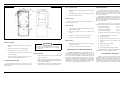
Figure 1 - Removing The Battery Pack ........................................................................................
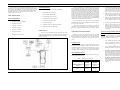
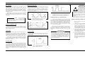
Figure 2 - Disassembly..................................................................................................................
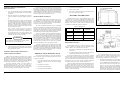
Figure 3 - Test Setup......................................................................................................................
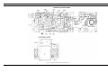
Figure 4 - Location Of Tuning Controls And Test Points............................................................
Figure 5 - Reference Oscillator (Input To PLL U201).................................................................
Figure 6 - Fin (Input to U201) .......................................................................................................
Figure 7 - Remp (Generated In U201)..........................................................................................
Figure 8 - SYN EN (Input To Pin 13 Of U201) ...........................................................................
Figure 9 - Typical Ni-Cad Cell Discharge Curve.........................................................................
Figure 10 - Alternate IF Option.....................................................................................................
1
2
3
4
7
7
7
7
8
8
This service section contains the necessary information
to align and troubleshoot the MPI-II (136-174 MHz) Personal Radio. This manual includes steps for disassembly and
procedures for replacing surface mount components and
integrated circuits. Preventive maintenance checks are provided as well as battery service data. The tests and procedures in this manual are intended to be used by a qualified
service technician.
In order to perform many of the following alignments,
tests and troubleshooting checks it will be necessary to
program the radio’s personality EEPROM to tailor the operation of the radio to stipulated requirements. Instructions
are offered which include the use of an IBM compatible
personal computer and appropriate software. If the radio is
properly functioning and has a preprogrammed personality,
alignment procedures can be initiated directly.
Conventional testing using the recommended alignment
procedures will verify proper operation of all of the radio’s
circuitry, with the following exceptions:
•
•
NOTE:TORX® is a Registered Trademark of Camcar
Division of Textron Inc.
BATTERY
CAUTION
ALWAYS remove the battery pack before disassembling the unit to avoid blowing the fuse or causing
other component damage.
1.
Turn the radio OFF.
2.
Place thumb on bottom of battery pack and press
battery pack toward the top of the radio as shown in
Figure 1.
3.
While pressing the battery pack toward the top of the
radio, push bottom of battery pack away from the
radio.
Data modulation circuitry in transmit mode
Data demodulation circuitry in receive mode
DISASSEMBLY PROCEDURE
The following section describes how to gain access to
the Transmit/Receive Board and the Synthesizer Board for
servicing. This section also provides the procedures to disassemble various assemblies from the radio.
TOOLS NEEDED
1.
No. 7 TORX®screwdriver
2.
No. 8 TORX®screwdriver
3.
.050 hex tool
4.
Flat blade screwdriver
5.
ST2312 spanner tool
6.
ST2311 spanner tool
7.
5/16 wrench
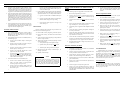
Figure 1 - Removing The Battery Pack
WARNING
Do not dispose of battery packs or batteries by
burning. To do so may cause an explosion.
1
S
E
R
V
I
C
E
S
E
C
T
I
O
N