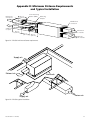
1
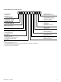
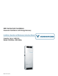
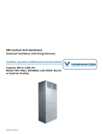
ERV
Energy Recovery Ventilators
Installation, Operation and Maintenance Instructions Manual
Capacity: 400 to 600 cfm
Model: ERV500i/e
©2012 Venmar CES Inc.
Table of Contents
Nomenclature.......................................................................................................................................................................3
Safety Considerations..........................................................................................................................................................5
General Information............................................................................................................................................................5
Installation............................................................................................................................................................................5
Check Equipment...........................................................................................................................................................5
Mount Unit.....................................................................................................................................................................5
Make Duct Connections.................................................................................................................................................6
Rigging and Placing the Unit (ERV500e only)..............................................................................................................7
Install Hoods (ERV500e only).........................................................................................................................................7
Install Access Panel Handles..........................................................................................................................................7
Remove All Internal Packaging.....................................................................................................................................7
Systems Integration.......................................................................................................................................................8
Electrical Connections....................................................................................................................................................8
Start-up.................................................................................................................................................................................9
Controls..........................................................................................................................................................................9
Frost Control.................................................................................................................................................................10
Sequence of Operation................................................................................................................................................10
Airflow Balancing........................................................................................................................................................10
System Service....................................................................................................................................................................11
Quarterly Maintenance...............................................................................................................................................11
Annual Maintenance...................................................................................................................................................11
Testing and Replacement of the Damper Actuator...................................................................................................12
Motor and Blower Removal........................................................................................................................................12
Cassette Removal.........................................................................................................................................................13
Cassette Service............................................................................................................................................................13
Appendix A: Roofcurb Detail............................................................................................................................................15
Appendix B: Dimensional Drawing...................................................................................................................................16
Appendix C: Hood Installation and Rigging.....................................................................................................................18
Appendix D: Minimum Distance Requirements and Typical Installation.......................................................................19
Appendix E: Components..................................................................................................................................................20
Appendix F: Equipment Data............................................................................................................................................21
Appendix G: Terminal Control Diagrams..........................................................................................................................22
Appendix H: Troubleshooting...........................................................................................................................................26
Manufacturer reserves the right to discontinue or change specifications or designs without notice or obligation.
vces-ERV-iom-1A – ERV500i/e
2
Nomenclature
ERV500i Nomenclature (400–700 cfm)
1
2
3
4
5
6
1. FROST CONTROL
D – Recirc defrost1
E – Exhaust only2
C – Non-defrost
N – Non-defrost, no wall control compatibility
2. VOLTAGE/SPEED
A – 120/1/60
3. INTERNAL PROTECTION
1 – 1” insulation, single wall
2 – 1” insulation, double wall
4. SENSOR CONTACTS
W – Wheel rotation sensor3
X – No sensor
5. EXTERNAL FINISH
S – Standard galvanized package
W – White prepaint package
7
8
9
10
10. ENERGY RECOVERY
1 – Aluminum wheel, no purge
9. FREE COOLING
S – Setpoint enthalpy controller
D – Differential enthalpy controller
T – Thermostat (dry bulb)
X – No free cooling controller
8. FILTRATION
S – Supply filter
E – Exhaust filter
B – Supply and exhaust filters
X – No filtration
7. EXTERNAL DISCONNECT
N – Non-fused disconnect switch4
X – No disconnect switch
6. OUTSIDE AIR DAMPER
1 – Insulated motorized
2 – Insulated spring return
3 – No damper
Notes:
1 When ordering recirc defrost, you must order an outside air damper. Recirc defrost option includes recirculation dry contacts for unoccupied mode.
2 Outside air damper required.
3 Units ordered with the wheel rotation sensor option must include a frost control option other than ‘N’.
4 Non-fused disconnect switch is field installed.
©Venmar CES Inc. 2012. All rights reserved throughout the world.
Illustrations cover the general appearance of Venmar CES products at the time of publication and Venmar CES reserves the
right to make changes in design and construction at any time without notice.
vces-ERV-iom-1A – ERV500i/e
3
ERV500e Nomenclature (400–700 cfm)
1
2
3
4
5
6
7
8
9
10
11
12
13
1. FROST CONTROL
E – Exhaust only1
C – Non-defrost
N – Non-defrost, no wall
control compatibility
2. VOLTAGE/SPEED
B – 208–120/1/60 - one-speed2
C – 230–120/1/60 - one-speed2
3. INTERNAL PROTECTION
1 – 1” insulation, single wall
2 – 1” insulation, double wall
4. SENSOR CONTACTS
W – Wheel rotation sensor3
X – No contacts, no sensor
5. EXTERNAL FINISH
G – Grey prepaint package
6. OUTSIDE AIR DAMPER
1 – Non-insulated motorized
2 – Insulated motorized
3 – Insulated spring return
4 – No damper
7. EXHAUST AIR DAMPER
1 – Backdraft (low leak)
2 – Non insulated motorized (low leak)
3 – Insulated motorized (low leak)
4 – No damper
14
14. ENERGY RECOVERY
1 – Aluminum wheel, no purge
13. FREE COOLING
S – Setpoint enthalpy controller
D – Differential enthalpy controller
T – Thermostat (dry bulb)
X – No free cooling controller
12. FILTRATION
S – Supply filter
E – Exhaust filter
B – Supply and exhaust filters
X – No filtration
11. RETURN AIR
B – Bottom return air
S – Side return air
10. SUPPLY DISCHARGE
D – Down supply discharge
E – End supply discharge
9. HOODS
H – Intake/exhaust hoods
X – No hoods5
8. EXTERNAL DISCONNECT
N – Non fused disconnect switch4
X – No disconnect switch
Notes:
1 Outside air damper required.
2 Requires a neutral wire with L1 and L2.
3 Units ordered with the wheel rotation sensor option must include a frost control option other than ‘N’.
4 Non fused disconnect switch is field installed.
5 Must order hoods when ordering dampers.
vces-ERV-iom-1A – ERV500i/e
4
Safety Considerations
Warning, Caution and Important notes appear throughout this manual in specific and appropriate locations to
alert Installing Contractors and maintenance or service
personnel of potential safety hazards, possible equipment
damage or to alert personnel of special procedures or instructions that must be followed as outlined below.
Warning
!
Identifies an instruction which, if not followed, might cause
serious personal injuries including possibility of death.
Caution
Identifies an instruction which, if not followed, might severely damage the unit, its components, the assembly or
final installation.
Hazards may exist within this equipment because it contains electrical and powerful moving components. Only
qualified service personnel should install or service this
equipment. Untrained personnel can perform basic maintenance such as maintaining filters. Observe precautions
marked in literature and on labels attached to the unit.
Follow all safety codes.
!
Warning
Disconnect the main power switches to the unit before
performing service or maintenance. Electric shock can
cause personal injury or death.
Important
Indicates supplementary information needed to fully
complete an instruction or installation.
General Information
The ERV500i ventilator is intended for installation within
a suspended ceiling space or mechanical room. The
ERV500e ventilator is intended for installation on a rooftop
with a factory supplied or field supplied roofcurb.
These ventilators provide 100% outdoor air ventilation
and provide energy recovery between the exhaust and
supply airstreams. The Energy Recovery Ventilators (ERVs)
use an enthalpy wheel for total energy recovery which
provides superior efficiency in hot and humid climates. In
addition, they provide excellent heat recovery in winter
and transfer moisture from exhausted air to the outdoor
air before supplying it to an occupied space.
Installation
Check Equipment
Move the unit to its installation location and remove packaging. See Appendix F for unit weight and specifications.
Inspect the exterior and interior of the equipment for damage. Ensure there is no damage to internal components
such as fans, motors, dampers, enthalpy wheel, insulation,
etc. File a claim with the shipping company if the unit is
damaged.
System Requirements
Consult local building codes and the National Electrical
Code for special installation requirements. Note additional
requirements below and in the Start-up section.
Mount Unit
Interior Mount
The unit should be installed to allow easy access for maintenance. Appendix B shows minimum clearance required
between front access and any obstruction to allow for
removal of components (fans, filters, enthalpy wheel). The
vces-ERV-iom-1A – ERV500i/e
front of the unit is defined in relation to the inlet ports
and outlet ports on the unit. Port location and overall dimensions are shown in Appendix B. Unit components are
shown in Appendix E.
5
In cold climates (−5°F [−20°C] design), the unit must be
mounted in a dry area (not exceeding 30% RH) to avoid
condensation on the exterior of the cabinet during winter
operation. Alternatively, accommodation must be made
for condensation on the cabinet exterior. Do not mount
units in an area where exposure to hot chimneys, electrical
panels or other hazards will occur.
A mounting location close to an exterior partition will minimize the length of insulated ductwork required. Exhaust
air to outside and inside air ducts must be insulated. Inlet
and exhaust hoods should be separated by a minimum of
10 feet [3,048 mm] to avoid outside cross contamination.
Ceiling Mount
The unit must be mounted level and may be hung with
threaded rod (field supplied) through the protruding frame
at the base of the unit. Hole centers are shown in the
overall dimensional drawings in Appendix B. Rubber or
seismic vibration isolation may be required in some regions
(field supplied and specified).
Surface Mount
Rooftop Mount (ERV500e Only)
Care must be exercised in locating the roofcurb for the
unit on the roof opening. The HVAC system should cross
enough roof supports to safely distribute the weight of the
system over the roof. For hole sizes of the units, see Appendix B. For more roofcurb information, see Appendix A.
Remove roofcurb from packaging. Assemble and install
accessory roofcurb in accordance with instructions shipped
with the curb. See Appendix A for curb dimensions. Install
cant strip, flashing and roof felt as per Appendix A.
Important
The gasketing of the unit to the roofcurb is critical for
a water-tight seal. Install gasket with the roofcurb as
shown in Appendix A. Improperly applied gasket can result in water leaks and poor unit performance.
Ductwork must be attached to the roofcurb, not the unit.
Consult with local authorities or your local building code
for minimal intake hood height from the roof to determine
the height of the roofcurb. See Appendix B for dimensions
of the unit.
The unit may be secured to a metal or wooden curb
fastened to the floor. If securing the unit to the curb
is required, fasteners and isolators may be used at the
mounting points on the frame protruding from the unit
(all mounting hardware is field supplied and specified).
Make Duct Connections
ERV500i
Port locations for the indoor unit are labeled in Figure B1.
An 18” [457 mm] long section of straight duct must be
used immediately after the supply fan to achieve optimal
fan performance. Transitions (field supplied) may be required to make connection with ductwork that is properly
sized for minimum noise and pressure loss. Both duct
connections to outside must be insulated to avoid condensation and heat loss. A continuous integral vapor barrier
must be used over the duct insulation.
Airflow rate balancing dampers are recommended for
both supply and exhaust ducts to allow for adjustment of
airflows as shown in Figure D1. Flexible connectors should
be installed close to the unit in the duct leading to occupied spaces to minimize noise transmission. All ports have
1” [25 mm] flanges to facilitate duct connection. Ensure
that fasteners used to make duct connection do not interfere with fans or dampers in the unit.
vces-ERV-iom-1A – ERV500i/e
Electric preheat, if used as frost control, must be installed
in the intake from outside at a minimum distance from the
unit port of 24” [610 mm].
ERV500e
On vertical discharge units, secure all ducts to the roofcurb
and building structure. Do not secure ductwork to the
unit. For duct size requirements, see Appendix B. Insulate
and weatherproof all external ductwork, joints and roof
openings with counter flashing and mastic in accordance
with applicable codes. Ductwork running through roof
decks must comply with local fire codes. Ducts passing
through unconditioned spaces must be insulated and covered with a vapor barrier. Flexible connectors should be
installed close to the unit in the duct leading to occupied
spaces to minimize noise transmission.
6
Rigging and Placing the Unit (ERV500e only)
Inspect the exterior and interior of the equipment for damage. Ensure there is no damage to internal components
such as fans, motors, dampers, enthalpy wheel, insulation
and structures. File a claim with the shipping company if
the unit is damaged.
Important
The hoods for these units are not installed from the factory and must be installed on site. They can be installed
prior to rigging the unit or after the unit is installed.
Hoods are shipped on top of the unit. When rigging
the unit, ensure that the hoods are secured and are not
damaged by the spreader bars. See Appendix C for hood
installation and rigging information.
Spreader bars are required to prevent damage to the roof
flange. Rollers may be used to move the unit across a roof.
Lifting holes are provided in the base rails as shown in Appendix C. For weights and overall dimensions, see Figure
B2.
Location
Maintain clearance around and above the unit to provide
proper airflow and service access. The fresh air intake hood
must be positioned away from sources of contamination
such as chimneys, exhaust vents, etc. Positioning the fresh
air intake opposite to the prevailing winds will reduce entry
of snow or moisture during periods of high winds.
Caution
All panels must be in place when rigging.
Install Hoods (ERV500e only)
Intake and exhaust hoods for these models are shipped
separately from the unit. See Appendix C for hood installation information. A quick connect for the damper motors
is provided to connect to the main body of the unit. Make
sure that all screws are secured to maintain proper support
and keep seals water-tight.
Install Access Panel Handles
Important
Securing door fasteners too tightly has negative effects
on the door gasket and should be avoided.
Handles for access panels are provided but must be installed on site. Handles and fasteners are secured on the
top of the unit. Remove from packaging and install according to Figure 1.
Access panel
Metal or
polyamide
handle
#10 x ¾ Screw
Figure 1: Access panel handles
Remove All Internal Packaging
Caution
Remove all ERV wheel packaging prior to start-up.
vces-ERV-iom-1A – ERV500i/e
Remove access panels and remove all packaging from the
unit. Note that there is packaging for the wheel support
during shipping. Removal of all of this packaging is critical.
7
Systems Integration
Forced Air System
When the unit is installed in conjunction with a forced
air system, the air handler and the network of ducts associated with it are used to distribute fresh air inside the
building. If this type of system is used, the main fan of the
air handler must operate continuously when the unit is on.
Fan interlock can be connected in the unit control box to
the integrated control board terminals J3-1 and J3-2. The
controller makes relay contact between these terminals
when the unit is operating, as shown in Figure 2.
2
1
1
J2
JU1G – Intermittent standy (IS)
JU1F – Extended defrost
COMM.
N/C
N/O
J1
J4
1 2 3
6
4
9
7
Separate Systems
Select locations for exhaust grilles and supply diffusers
to provide effective ventilation and avoid short circuiting
airflows through the space. Adjustable dampers should be
provided at every grille and diffuser to make balancing of
the system possible.
Exterior Hoods
48644 power
control board
3
Fresh air from the unit should be introduced into the return duct of the air handler at a point no less than 6 feet
[1,829 mm] upstream of the air handler. The duct connection for stale air to the unit should be made on the return
air duct at least 2 feet [610 mm] upstream of the fresh air
duct connection.
The outside air intake hood must be positioned away from
sources of contamination. A screen with ¼” [6 mm] grid is
recommended to prevent intake of debris and pests. The
screen should be removable in cold climates where frost
blockage may occur.
JU1
+
+
+
+
+
+
+
+
+
+
+
+
+
+
ABCDEFG
F F I OC OL Y R G B
J3
Fan interlock
contacts
Figure 2: Fan interlock control board
Electrical Connections
!
Warning
Unit cabinet must have an uninterrupted, unbroken electrical ground to minimize the possibility of personal injury
if an electrical fault should occur. Failure to follow this
warning could result in the Installer being liable for personal injury of others.
All field wiring must comply with NEC and local requirements. In Canada, electrical connections must be in accordance with CSA C22.1 Canadian Electrical Code Part One.
Table 1: ERV500 Power Supply
ERV500i
ERV500e
Line voltage
120
230
Power Supply
mca
9.4
11.1
These units may or may not have a factory installed disconnect switch. If disconnect is field supplied, provide a
disconnect as per NEC. Use copper conductors only.
mop
10
15
Field Connection
A high voltage connection (shown in Figure 3) is located
on the outside of the unit with knockout. A field installed
vces-ERV-iom-1A – ERV500i/e
8
disconnect switch must use a liquid-tight connector between the disconnect switch and the outside panel of the
unit eliminating any water penetration into the control
box. A wiring diagram is located on the control box lid inside of the unit.
The low voltage connection runs through the roofcurb and
roof opening to the bottom panel. Low voltage remote
wiring terminal is located inside the unit on the control
box. Installer must provide wiring for the controls that may
be supplied optionally.
Rooftop unit
(cutaway shown)
¾” locknut
(as seen from
inside the unit)
¾” x 1-3/8” liquid-tight connector
¾” locknut
Line disconnect switch
(cutaway shown)
Figure 3: High voltage field connection
Start-up
Controls
A low voltage remote control wiring interface is provided on
the unit. The installer must provide wiring for the controls
that may be supplied optionally. The optional wall controls
require a four-wire LVT 24 gauge (or equivalent). This control is 12 VDC. Other terminals are 24 VAC or dry contact
control. Terminals are available for the following controls:
•
•
•
•
•
•
•
Low-Com-High
–– Makes dry contact for speed setting.
Wall control
–– Four-wire LVT 24 gauge minimum (12 VDC).
Occupied timer/sensor
–– Needs dry contact to operate. 24 VAC is required
when timer is used. Do not use with Xtra wall
control.
Enthalpy control
–– 24 VAC.
Remote fan control
–– Requires single pole, double throw switch.
Low temperature control
–– Makes dry contact.
Wheel rotation sensor
vces-ERV-iom-1A – ERV500i/e
–– Makes dry contact.
CO2 ventilation control
–– Makes dry contact.
• Unoccupied recirc contacts (ERV500i only)
–– 24 VAC.
• Smoke detector
–– Makes dry contact.
For more information on the controls available for the
energy recovery ventilators, see the following Appendix G
references:
•
•
•
•
•
•
•
•
•
•
Wall Control Connection
Occupied Timer/sensor Connection
Enthalpy Control
Remote Fan Control
Low Temperature Control
Wheel Rotation Sensor
CO2 Ventilation Control
Unoccupied Recirc Contacts (ERV500i only)
Smoke Detector
9
Frost Control
The unit functions are controlled by integrated unit controls including recirculation/exhaust only defrost (optional).
In cold temperatures, frost control cycles will remove frost
from the enthalpy wheel to maintain proper operation.
This removal of frost occurs when a damper closes the
outside air port and allows room air to circulate through
the enthalpy wheel and back to the vented room. Each
unit has different frost control requirements and the
schedules are shown on the wiring diagrams located in
the unit control box.
Exhaust Only
Supply fan is de-energized. There is no outdoor air ventilation for the duration of frost control. Enthalpy wheel
maintains rotation.
Recirculation (ERV500i Only)
The exhaust fan is de-energized. There is no outdoor
air ventilation for the duration of frost control. Enthalpy
wheel continues to rotate.
Sequence of Operation
Before start-up, check the unit for obstructive packaging,
objects near or in blowers, dampers, enthalpy wheel, etc.
Once installation is complete, check all modes of operation to ensure that the unit is working properly. Close the
doors and check for operation on Low and High using the
dry contacts labeled Low-Com-High on the side of the
unit. If there is a wall control, check the operation of all
speed settings.
•
•
Units Equipped with Frost Control
When the unit is in defrost, unoccupied mode, or off, the
ventilation damper will close. The ventilation damper will
open during ventilation.
•
Important
On initial power up, the unit will perform a system check
and operate at high speed for five seconds.
•
Unit Checkpoints
•
•
Power connected, no ventilation call – Both fans
are off, frost control damper (if equipped) closes off
fresh air from outside.
Power connected, low speed call (if equipped) – Both
fans on low speed, frost control damper (if equipped)
•
opens fresh air from outside and closes recirculation
opening. If unit is single speed, it will come on that
speed on a call for low or high.
Power connected, high speed call – Both fans on
high speed, frost control damper (if equipped) opens
fresh air from outside and closes recirculation opening. If unit is single speed, it will come on the speed
on a call for low or high.
Power connected, occupied timer/sensor connection
open (unoccupied mode) – Both fans are off, frost
control damper (if equipped) closed off fresh air from
outside.
Power connected, enthalpy control contacts closed,
unit ventilating – Wheel stops rotating, fans stay on
set speed, frost control damper (if equipped) is open.
Power connected, enthalpy control contacts closed,
unit not in ventilation mode – Wheel does not rotate,
fans come on low speed (if equipped), if unit is single
speed, it will come on that speed on a call for low or
high, frost control damper (if equipped) is open.
Power connected, recirculation defrost (optional) is
factory installed – Recirc contacts are closed, exhaust
fan is de-energized, supply fan runs and recirculation
damper opens (ERV500i only).
Airflow Balancing
For proper performance the unit must operate with equal
supply and exhaust flow rates. Permanent or temporarily
field supplied and installed flow measuring stations (FMS)
and magnehelic gauges can be used to measure and compare supply flow with exhaust flow. Appendix D shows
proper installation of the FMS in the “exhaust air from
space” and “supply air to space” ducts for measuring exhaust and supply flows respectively.
ferences in air density, especially when balancing during
extreme cold outside conditions. Air density variations can
effect the FMS by more than 15%.
The FMS should be located downstream from straight
sections of duct and not immediately after fans or obstructions that will cause turbulent flow. See Appendix D which
illustrates minimum distances from fan, elbows or transitions for best operation.
It is important to locate the FMS in the “warm side” ductwork as described above to minimize the effect of difvces-ERV-iom-1A – ERV500i/e
10
Flow control dampers should be installed downstream
from the FMS so flow through the FMS is not disturbed.
Dampers can then be adjusted to equalize flow rates in
the ducts.
Setting Flow Rate
Flow rates should be balanced with units operating on
high speed. A damper must be used to establish the minimum duct pressure required so fans do not operate in
overload regions. Set the dampers to establish the minimum duct pressure required. Further adjust the dampers
to reduce flow to the desired, balanced rate.
Where space is limited in the outdoor air or exhaust air
ducts, pressure drop readings can be taken across the
enthalpy wheel rotor and extrapolated from Table 2. Heat
recovery performance is tested in accordance to AHRI
Standard 1060 and is accurate to within +/− 5% if there is
no dirt buildup in the heat recovery wheel.
Table 2: ERV500i/e Enthalpy Wheel Airflow vs. Velocity
and Pressure Drop
Airflow (cfm)
Airflow performance can be measured using flow measuring stations (FMS) as described above or performing air
flow measurements using ASHRAE suggested methods.
Velocity (fpm) Pressure Drop (in. w.g.)
300
417
0.45
400
556
0.60
500
695
0.76
600
834
0.93
700
973
1.10
System Service
Quarterly Maintenance
!
Warning
Disconnect the main power switch to the unit before performing service and maintenance procedures.
Quarterly maintenance (every three months) should include:
Air Filters
placement may be required under extremely dirty operating conditions. For filter specifications, see Appendix F.
Cassette Panels and Interior of Unit
The foil faced insulation surfaces and cassette panels
should be wiped clean with a soft cloth and mild cleaning
solution.
The standard medium efficiency filters are disposable and
should be replaced every three months. More frequent re-
Annual Maintenance
Annual maintenance should include:
Air Filters
Replace medium efficiency filters.
Rotor
Interior of Unit
Brush.seal
Wash the foil faced insulation surfaces with a soft cloth
and mild cleaning solution.
Enthalpy Wheel
No cleaning of the enthalpy wheel is required, it is selfcleaning due to the opposing airflows. If the enthalpy
wheel needs to be cleaned, use low pressure air or a
vacuum. Wash the cassette panels with a soft cloth and
mild cleaning solution. Visually inspect the cassette brush
seals (shown in Figure 4), perimeter seal and drive belt for
proper operation.
Figure 4: Brush seal
Fans
The blower wheels and fan housing should be checked
for dirt build-up. If they are dirty, it will be necessary to
remove the blower assembly to clean the dust out through
the fan mouth.
System Operation Check
Verification of all control modes should be checked to ensure proper operation. Refer to Start-up Section.
vces-ERV-iom-1A – ERV500i/e
11
Testing and Replacement of the Damper Actuator
!
Warning
Disconnect the main power switch to the unit before performing service and maintenance procedures.
After disconnecting the power from the unit, determine
if the actuator is defective. Disconnect the 24V power
source. Connect the actuator directly to a 24V power
source with an appropriate cable. If the damper operates
correctly, the problem is either in the wiring connections
or main circuit board.
If the actuator does not work, it must be replaced. Loosen
the nuts on the jack shaft clamp, remove the actuator.
Tighten the clamp on the damper jack shaft. Test for
proper operation.
Motor and Blower Removal
Exhaust
After disconnecting the power from the unit, disconnect all
the plug-in connectors on the left side of the control box.
Figure 5: Disconnect plug-in connectors
Remove the four Phillips head screws holding the control
box cover. Using a ¼” nut driver, remove the four hex head
screws holding the control box to the unit. Remove the
control box to gain access to the exhaust blower assembly.
To remove the exhaust blower, unscrew the two wing
nuts used to fasten the blower assembly to the middle
shelf in the unit. Rotate the blower assembly and slide it
out of the unit.
Figure 7: Remove exhaust blower
Supply
After disconnecting the power from the unit, disconnect
the three-wire connector between the supply motor and
control box.
Figure 6: Remove control box cover
Figure 8: Disconnect three-wire connector
vces-ERV-iom-1A – ERV500i/e
12
Warning
!
Disconnect the main power switch to the unit before performing service and maintenance procedures.
To remove the supply blower, unscrew the four wing nuts
used to fasten the blower assembly to the middle shelf of
the unit. Slide the blower assembly out of the unit.
Figure 9: Remove supply blower
Cassette Removal
After disconnecting the power from the unit, disconnect
the two three-wire connectors located on the metal frame
of the cassette assembly. Both connectors are positioned
at the front of the cassette assembly, one connector located at the top right position and the other at the bottom
left position on the cassette frame. Disconnect the threewire connector from the control box being used to supply
power to the cassette motor.
Important
Use extreme care when removing or installing the cassette assembly. Damage to the cassette media may result
in poor unit efficiency and may void the warranty.
Figure 10: Remove cassette assembly
Cassette Service
Brush Seal
Complete the following instructions to replace the brush
seal on both sides of the cassette. On the belt side of the
cassette, remove the two Phillips screws holding the air
filter guide to the cassette assembly. Remove the additional Phillips screw holding the brush seal to the cassette
assembly. On the motor side of the cassette, remove the
three Phillips screws holding the brush seal to the cassette
assembly.
Figure 11: Remove screws holding brush seal to cassette
assembly
vces-ERV-iom-1A – ERV500i/e
13
!
Warning
Disconnect the main power switch to the unit before performing service and maintenance procedures.
Using a 7/16” nut driver, remove the four ¼” bolts holding
the cassette beam to the cassette frame. The cassette beam
can now be removed and placed aside to re-install later.
Install the new brush seals so that the bristles come in
contact with the cassette. Reverse the procedures above to
re-install the brush seals and the air filter guide.
Drive Belt
To replace the cassette drive belt, the brush seal located on
the drive belt side of the cassette must be removed. Complete the steps in the previous section for the removal of the
brush seal prior to completing the following procedures.
The cassette beam assembly must be removed to gain
access to the cassette drive belt. To remove the cassette
beam assembly, remove the three Phillips screws used to
fasten the cassette beam cover.
Figure 14: Remove cassette beam bolts
Remove the outer half of the adjustable sheave (pulley).
Using a 5/32” Allen key, loosen the set screw located
on the outer half of the adjustable sheave. Remove the
outer half of the adjustable sheave by turning it counterclockwise. This sheave piece is threaded and therefore it
will take a few rotations to completely remove it. Once
removed, slide the belt off the cassette.
Figure 12: Remove cassette beam assembly
Using a 1/8” Allen key, loosen the two set screws used to
tighten the cassette bearing to the cassette shaft. The set
screws are located in-line with the cassette shaft, between
the cassette and the cassette beam. After loosening one
set screw, it will be necessary to rotate the wheel a half
turn to access the second set screw.
Figure 15: Remove belt from cassette
Install the new belt onto the cassette and adjustable
sheave (pulley). Re-install the outer half of the adjustable
sheave by rotating it clockwise onto the threaded shaft.
This process will be used to tighten the belt around the
perimeter of the cassette. Do not tighten the belt onto
the cassette until the beam assembly has been reinstalled.
Reverse the above procedures to re-assemble the cassette
assembly. It will also be necessary to complete the steps in
the previous sections that were used to install the cassette
brush seal and the cassette.
Figure 13: Loosen set screws
vces-ERV-iom-1A – ERV500i/e
14
Appendix A: Roofcurb Detail
SECTION A-A
Unit
3/8” [10] gasket
(supplied with curb)
Wood nailer
A
A
Supply
air
Return air
Overhang:
3” [76]
Unit
baserail
Counter flashing
(field supplied)
Roofing felt
(field supplied)
Cant strip
(field supplied)
Rigid insulation
(optional)
Roofing material
(field supplied)
2.375”
[60]
17.500”
[445]
14.500”
[368]
5.500”
[140]
64.000”
[1,626]
15.250”
[387]
1.500” typ.
[38]
61.000”
[1,549]
15.000”
[381]
1.500” typ.
[38]
Rigid insulation (styro)
Wood nailer
Note: Dimensions in [ ] are millimeters.
Figure A1: ERV500e roofcurb
vces-ERV-iom-1A – ERV500i/e
15
vces-ERV-iom-1A – ERV500i/e
2.750”
[70]
4.500”
[114]
5.250” [133]
Supply air
opening
4.000”
[102]
LEFT VIEW
5.750”
[146]
Return air
opening
Supply air
24.000”
[610]
Low voltage connection
(leave 16” [406] in
front for access)
Electrical
connection box
8.000”
[203]
Return air
8.000”
[203]
14.000”
[356]
BOTTOM VIEW
FRONT VIEW
58.000”
[1,473]
Supply fan, control box, filter,
cassette access panel
52.000”
[1,321]
14.000”
[356]
1.500”
[38]
54.000”
[1,372]
TOP VIEW
23.000”
[584]
Hanging mount hole Ø 0.625” [16]
C
Note: If the unit is to be hung, materials
required to hang the unit will be
supplied by others.
16.000”
[406]
A
27.750”
[705]
56.000”
[1,422]
2.000”
[51]
19.5
43.0
63.5
190.0
C
D
TOTAL
Note:
Requires a minimum of
24.000” [610] clearance
to open door and remove
internal components.
RIGHT VIEW
14.000”
[356]
Outdoor air
opening
5.750”
[146]
22.000”
[559]
28.8
86.0
Kg
24.0
13.7
ERV500i
LBS
53.0
30.5
PTS
A
B
Exhaust air opening
Recirculation defrost
port (optional)
Outdoor air
Exhaust air
D
9.375”
[238]
23.000”
[584]
B
4.000”
[102]
22.000”
[559]
2.000”
[51]
8.000”
[203]
5.250” [133]
5.000” [127]
Notes:
Dimensions in [ ] are millimeters.
Center of gravity
Direction of airflow
Appendix B: Dimensional Drawing
Figure B1: ERV500i unit dimensions
16
Figure B2: ERV500e unit dimensions
vces-ERV-iom-1A – ERV500i/e
17
17.843”
[453]
7.831”
[199]
LEFT VIEW
24.000”
[610]
23.000”
[584]
Exhaust air
7.100”
[180]
19.981”
[508]
Field
power
supply
4.481”
[114]
A
6.776”
[172]
24.000”
[610]
Exhaust air hood
15.500”
[394]
27.000”
[686]
6.100” [155]
Exhaust air
12.380”
[314]
3.810”
[97]
10.257”
[261]
4.983”
[127]
5.310”
[135]
Air return
bottom
SECTION VIEW AA
A
B
14.000”
[356]
A
30.831”
[783]
RIGHT VIEW
6.047”
[154]
5.150”
[131]
Air supply bottom
15.260”
[388]
10.250”
[260]
9.200”
[234]
27.000”
[686]
13.500”
[343]
End supply air
16.000”
[406]
BACK VIEW
6.500”
[165]
Connection Sizes
7/8”
1 1/8”
9.500” Side return
[241] air
14.393”
[366]
A Low voltage knockout
B Low voltage knockout
Connection Table
ERV500e
Notes:
Dimensions in [ ] are millimeters.
Direction of airflow
Note: Requires a minimum of 24.000” [610]
clearance to remove internal components.
23.000”
[584]
5.700”
[145]
2.705”
[69]
16.000”
[406]
Supply air
15.000”
[381]
FRONT VIEW
Return air
68.000”
[1,727]
TOP VIEW
52.000”
[1,321]
Outdoor air hood
Outdoor air
Outdoor air
22.000”
[559]
24.090”
[612]
1.000”
[25]
11.091”
[282]
Appendix C: Hood Installation and Rigging
Detail A
See Detail A
Screw: #10 x 3/4
Detail B
Male
Black
Female
Female
See Detail B
Black
Male
White
White
Figure C1: ERV500e hood installation
Spreader bars
Note:
Remove all packaging before beginning to
rig the unit onto the installed roofcurb.
Figure C2: ERV500e rigging
vces-ERV-iom-1A – ERV500i/e
18
Appendix D: Minimum Distance Requirements
and Typical Installation
Exhaust air
from space
Min. 36”
[914 mm]
Flow measuring
station (FMS)
Balancing
damper
Flexible duct
connection
Supply air
to space
Min. 36”
[914 mm]
Min. 12”
[305 mm]
Exhaust air
to outside
Min. 36”
[914 mm]
Supply air
from outside
Figure D1: ERV500i minimum distance requirements
Supply air
Exhaust air
Roofcurb
Supply air
Return air
Figure D2: ERV500e typical installation
vces-ERV-iom-1A – ERV500i/e
19
Appendix E: Components
1
2
5
10
7
11
3
6
Item
1
2
3
4
5
6
7
8
9
10
11
4
9
8
Description
Supply blower
Supply blower motor
Exhaust blower
Exhaust blower motor
Control box
Supply filter
Exhaust filter
Damper actuator
Intake damper
Enthalpy wheel
Wiper seal
Some unit components listed above are optional.
Consult the unit nomenclature for standard and
optional components.
Figure E1: ERV500i unit components
17
13
11
1
2
10 14 4
19
3
5
7
6
9
8
15
12
16
18
19
1
2
3
Item
1
2
3
4
5
6
7
8
9
10
11
12
13
14
15
16
17
18
19
Description
Housing
Fan
Fan motor
Enthalpy wheel
Wheel drive motor
Wheel drive pulley
Wheel drive belt
Wheel perimeter seal
Wheel wiper seal
Damper actuator
Damper intake
Exhaust damper actuator
Exhaust damper
MEF supply filter set (two per set)
MEF exhaust filter set (two per set)
Oudoor air intake hood
Exhaust air hood
Aluminum mesh prefilter
Control box
Some unit components listed above are optional.
Consult the unit nomenclature for standard and
optional components.
Figure E2: ERV500e unit components
vces-ERV-iom-1A – ERV500i/e
20
Appendix F: Equipment Data
Table F1: ERV500 Equipment Data
ERV500i
ERV500e
Rated airflow (cfm)
559 cfm @ 0.5” w.g.
507 cfm @ 0.50” w.g.
Shipping weight
320 lbs [145 kg]
320 lbs [145 kg]
Shipping dimensions (L x W x H) 57.5” x 24.75” x 24” [1,461 x 629 x 610 mm] 68” x 27” x 23” [1,727 x 686 x 584 mm]
Fans
Impeller (forward centrifugal)
Motor
8.5” diameter x 3.5” width
[216 mm diameter x 89 mm width]
¼ hp supply and exhaust, two-speed on high
8.5” diameter x 3.5” width
[216 mm diameter x 89 mm width]
¼ hp supply, ¾ hp exhaust, single-speed
10” x 20” x 2” disposable
[254 x 508 x 51 mm disposable]
10” x 20” x 1” disposable
[254 x 508 x 25 mm disposable]
Supply and exhaust filters
Quantity: 1 per airstream MEF
vces-ERV-iom-1A – ERV500i/e
21
Appendix G: Terminal Control Diagrams
Wall Control Connection
Occupied Timer/sensor Connection
Two types of remote wall controls are available:
Occupancy control is achieved by connection to the terminal interface shown below. These terminals require a dry
contact which could be provided by a number of types of
controls such as a timer, light sensor, occupancy sensor,
Building Management System or other. The unit will not
operate unless these contacts are closed!!
1. Standard wall control with fan switch and dehumidistat control.
2. Xtra wall control with fan mode selection, dehumidistat control and maintenance indicator.
The remote wall controls work with the integrated electronic controls within the unit to control ventilation sequences. Each wall control above has different features
and requires four-wire connection to the unit as shown
below. Without the wall control, fans can be operated
with dry contacts or a switch as in Figure G5.
The drawing below shows a factory installed jumper and
programmable timer option.
JUMPER
(factory installed)
NSB Timer
OCCUPANCY CONTROL
(field installed)
CONTROL CONTACTS
1
BLACK
2
RED
CONTROL CONTACTS
1
BLACK
2
RED
GREEN
11
YELLOW
12
LOW
13
3
COMMON
14
4
HIGH
15
5
DIRTY
FILTER
INDICATOR
16
6
(+) 24 VAC
(1.5A–24 VAC)
17
7
(ERV UNITS)
18
8
19
9
20
10
WALL CONTROL
1
1
GREEN
BLACK
11
WALL CONTROL
JUMPER
2
3
4
LOW
OCCUPIED
TIMER/
SENSOR
4
5
YELLOW
RED
Wall
Control
3
JUMPER
CONTROL CONTACTS
12
13
14
HIGH
15
DIRTY
FILTER
INDICATOR
16
(1.5A–24 VAC)
17
(−) 24 VAC
(40 VA)
6
(+) 24 VAC
7
(ERV UNITS)
8
9
10
ENTHALPY
(ERV UNITS)
(RECIRC UNITS)
WHEEL
ALARM
OPTION
(24 VAC)
UNOCC.
RECIRC
CONTACTS
A
FIELD WIRED
TERMINALS
B
18
19
20
CLASS 2 VOLTAGE
NOTE:
Connections are all dry contacts
except wall control, wheel alarm
contacts and 24 VAC power contacts.
Use of 24 VAC circuit requires
isolating contacts (ex. thermostat)
to prevent interconnection of
Class 2 outputs.
Figure G1: Wall control connection
Important
All controls accessories (ex. night setback timer, CO2
controller, enthalpy controller, smoke detector or wheel
rotation sensor) intended to provide a contact closure for
occupancy control across terminals 3 and 4 cannot be
used in conjunction with the Xtra wall control.
If a wall control is required in addition to any of these
options, only the standard wall control may be used.
Without these options, a factory installed jumper across
terminals 3 and 4 must be installed.
vces-ERV-iom-1A – ERV500i/e
2
3
4
(+) 24 VAC
7
(ERV UNITS)
9
ENTHALPY
12
LOW
OCCUPIED
TIMER/
SENSOR
13
COMMON
14
HIGH
15
DIRTY
FILTER
INDICATOR
16
(1.5A–24 VAC)
17
(−) 24 VAC
(40 VA)
(ERV UNITS)
(RECIRC UNITS)
WHEEL
ALARM
OPTION
(24 VAC)
UNOCC.
RECIRC
CONTACTS
A
11
5
(40 VA)
10
5
(−) 24 VAC
6
8
COMMON
OCCUPIED
TIMER/
SENSOR
GREEN
YELLOW
WALL CONTROL
M
FIELD WIRED
TERMINALS
B
CLASS 2 VOLTAGE
ENTHALPY
(ERV UNITS)
(RECIRC UNITS)
WHEEL
ALARM
OPTION
(24 VAC)
UNOCC.
RECIRC
CONTACTS
FIELD WIRED
TERMINALS
A
B
18
19
20
CLASS 2 VOLTAGE
NOTE:
Connections are all dry contacts
except wall control, wheel alarm
contacts and 24 VAC power contacts.
NOTE:
Connections are all dry contacts
except wall control, wheel alarm
contacts and 24 VAC power contacts.
Use of 24 VAC circuit requires
isolating contacts (ex. thermostat)
to prevent interconnection of
Class 2 outputs.
Use of 24 VAC circuit requires
isolating contacts (ex. thermostat)
to prevent interconnection of
Class 2 outputs.
Figure G2: Occupied timer/sensor connection
Important
All controls accessories (ex. night setback timer, CO2
controller, enthalpy controller, smoke detector or wheel
rotation sensor) intended to provide a contact closure for
occupancy control across terminals 3 and 4 cannot be
used in conjunction with the Xtra wall control.
If a wall control is required in addition to any of these
options, only the standard wall control may be used.
Without these options, a factory installed jumper across
terminals 3 and 4 must be installed.
Enthalpy Control
Energy Recovery Ventilators (ERVs) can be controlled by
an enthalpy controller that switches between free cooling
and AC unit cooling. When free cooling is possible, the
ERV will ventilate without energy recovery (the enthalpy
wheel stops) on a call for cooling. The ventilation rate is
not affected. If the unit is not operating, enthalpy control
contact will initiate low speed ventilation. The enthalpy
control must be connected in conjunction with a cooling
thermostat control to prevent free cooling from initiating
in heating seasons as shown below.
22
CONTROL CONTACTS
CONTROL CONTACTS
1
THERMOSTAT
(FIELD SUPPLIED)
R
GREEN
11
1
BLACK
2
RED
WALL CONTROL
RED
2
3
OCCUPIED
TIMER/
SENSOR
4
TO AC UNIT
COIL (24 VAC)
5
12
LOW
13
COMMON
14
HIGH
15
DIRTY
FILTER
INDICATOR
16
(−) 24 VAC
GREEN
11
YELLOW
12
LOW
13
COMMON
14
HIGH
15
DIRTY
FILTER
INDICATOR
16
(1.5A–24 VAC)
17
REMOTE FAN SWITCH
WALL CONTROL
YELLOW
C
JUMPER
Y
BLACK
3
4
OCCUPIED
TIMER/
SENSOR
LOW
HIGH
(40 VA)
TO AC UNIT
COIL (GND)
6
(+) 24 VAC
7
(ERV UNITS)
8
+
−
−
A/ENT
SENSOR
LOW HI
(RECIRC UNITS )
A
10
GND
UNOCC.
RECIRC
CONTACTS
(24 VAC)
24 VAC
FIELD WIRED
TERMNIALS
B
20
R
1
JUMPER
TO AC UNIT
COIL (24 VAC)
3
4
GREEN
OCCUPIED
TIMER/
SENSOR
5
(−) 24 VAC
6
(+) 24 VAC
TO AC UNIT
COIL (GND)
B
R
NO CM
W
NC
8
9
T675A TEMP.
CONTROLLER
10
(ERV UNITS)
12
LOW
13
COMMON
14
HIGH
15
DIRTY
FILTER
INDICATOR
16
(1.5A–24 VAC)
(ERV UNITS)
(RECIRC UNITS )
(24 VAC)
A
UNOCC.
RECIRC
CONTACTS
FIELD WIRED
TERMNIALS
B
17
A
FIELD WIRED
TERMINALS
B
18
19
20
Low Temperature Control
The fans of the ERV can be controlled using a setpoint low
temperature controller. If the supply air discharge temperature falls below the setpoint on the low temperature
controller, the contacts between R–W break, therefore,
de-energizing the fans and closing the outside air damper.
Important
18
19
20
CLASS 2 VOLTAGE
Setpoint PN 1604130 (T675A)
UNOCC.
RECIRC
CONTACTS
Figure G5: Remote fan control
YELLOW
ENTHALPY
WHEEL
ALARM
OPTION
WHEEL
ALARM
OPTION
(24 VAC)
11
(40 VA)
7
(RECIRC UNITS)
Use of 24 VAC circuit requires
isolating contacts (ex. thermostat)
to prevent interconnection of
Class 2 outputs.
BLACK
RED
(ERV UNITS)
CLASS 2 VOLTAGE
WALL CONTROL
2
8
ENTHALPY
Note: Not all units have two speeds.
Single speed units will be activated
with either Low-Com or High-Com
connection.
NOTE:
Connections are all dry contacts
except wall control, wheel alarm
contacts and 24 VAC power contacts.
CONTROL CONTACTS
C
7
(ERV UNITS)
9
Figure G3: Setpoint/differential enthalpy control
Y
(+) 24 VAC
10
Use of 24 VAC circuit requires
isolating contacts
(ex. thermostat) to prevent
interconnection of Class 2
outputs.
THERMOSTAT
(FIELD SUPPLIED)
6
19
NOTE:
Connections are all dry contacts
except wall control, wheel alarm
contacts and 24 VAC power
contacts.
A/DIFF-ENT ENTHALPY CONTROL
(−) 24 VAC
18
CLASS 2 VOLTAGE
MOUNTED IN OUTDOOR AIRSTREAM
Setpoint PN 500053119S (A/Diff-ENT)
Differential PN 500053120S (A/Ent)
MOUNTED IN
RETURN AIRSTREAM
(1.5A–24 VAC)
(ERV UNITS)
WHEEL
ALARM
OPTION
9
+
ENTHALPY
5
(40 VA)
17
NOTE:
Connections are all dry
contacts except wall control,
wheel alarm contacts and
24 VAC power contacts.
Use of 24 VAC circuit requires
isolating contacts
(ex. thermostat) to prevent
interconnection of
Class 2 outputs.
Figure G4: Thermostat (dry bulb) control
Remote Fan Control
Remote fan control can be achieved by connecting dry
contact controls to the terminal interface at terminals
labeled: Low-Com-High (not all units have two speeds).
Placing a jumper across the Low and Com terminals will
put the unit in low speed ventilation or placing a jumper
across the High and Com terminals will put the unit into
high speed. Do not jumper all three terminals together.
These controls could also be the following: SPDT switch,
dehumidistat, CO2 sensor, light sensor, heat sensor, timer,
Building Management System, etc. Figure G5 represents a
switch connected to the unit.
An Xtra wall control cannot be used with a low temperature control.
The remote bulb sensor must be placed downstream of
the supply air fan discharge.
CONTROL CONTACTS
NOTE:
1. R–W breaks on temperature fall
2. Sensing bulb is placed in supply
airstream after the energy exchanger
1
BLACK
2
RED
GREEN
11
YELLOW
12
LOW
13
COMMON
14
HIGH
15
DIRTY
FILTER
INDICATOR
16
(1.5A–24 VAC)
17
WALL CONTROL
R
3
B
4
W
5
OCCUPIED
TIMER/
SENSOR
(−) 24 VAC
(40 VA)
6
(+) 24 VAC
7
(ERV UNITS)
T675A SETPOINT CONTROL
Field installed
low temperature unit control
8
9
10
ENTHALPY
(ERV UNITS)
(RECIRC UNITS)
WHEEL
ALARM
OPTION
(24 VAC)
UNOCC.
RECIRC
CONTACTS
A
FIELD WIRED
TERMINALS
B
18
19
20
CLASS 2 VOLTAGE
NOTE:
Connections are all dry contacts
except wall control, wheel alarm
contacts and 24 VAC power contacts.
Caution
Use of 24 VAC circuit requires
isolating contacts (ex. thermostat)
to prevent interconnection of
Class 2 outputs.
Do not use a wall control and remote fan switch at the
same time. Damage to the unit may occur.
Figure G6: Low temperature control
vces-ERV-iom-1A – ERV500i/e
23
Wheel Rotation Sensor
ERVs can be equipped with a wheel rotation sensor option. This option cannot be ordered for a non-defrost unit.
This option cannot be used in conjunction with a digital
wall control and must be ordered with a control board.
With the wheel rotating, the wheel rotation sensor board
activates the relay coil and closes the ‘NO’ (normally open)
set of contacts across the occupied/timer sensor contacts
(pin 3 and 4), allowing the unit to operate. If the wheel
rotation stops (unless in an enthalpy state, defrost mode
or unoccupied condition), the contacts will be open and
cause the motors to shut down and the dampers (optional) to close.
Important
CONTROL CONTACTS
1
2
WRS BOARD RELAY
3
'NC' CONTACTS
(normally closed –
opens on wheel failure)
J1 J2
DELAY
24 VAC LIGHT or INDICATOR
(supplied by others)
4
5
6
(+) 24 VAC
7
(ERV UNITS)
24V = 24 VAC
COM = COMMON
SEN = SENSOR
8
9
CAUTION
120 VAC
13
COMMON
14
HIGH
15
DIRTY
FILTER
INDICATOR
16
(1.5A–24 VAC)
17
(ERV UNITS)
(RECIRC UNITS)
WHEEL
ALARM
OPTION
(24 VAC)
UNOCC.
RECIRC
CONTACTS
A
FIELD WIRED
TERMINALS
B
18
19
20
CLASS 2 VOLTAGE
NOTE:
Connections are all dry contacts
except wall control, wheel alarm
contacts and 24 VAC power contacts.
Use of 24 VAC circuit requires
isolating contacts (ex. thermostat)
to prevent interconnection of
Class 2 outputs.
CO2 Ventilation Control
ERVs can be controlled by a CO2 controller that can be
connected to fan control Low-Com-High (not all units
have two speeds). As the CO2 levels exceed acceptable
limits, the dry contact across High-Com is closed, raising
high speed fan ventilation.
1
BLACK
CO2 SENSOR
2
RED
GREEN
11
YELLOW
12
LOW
13
WALL CONTROL
NC
8
7
6
FACTORY MOUNTED
JUMPER
RELAY
COM
3
4
OCCUPIED
TIMER/
SENSOR
COMMON
14
HIGH
15
DIRTY
FILTER
INDICATOR
16
(1.5A–24 VAC)
17
5
NC
NO
4
3
5
(−) 24 VAC
2
(40 VA)
COM SEN
ALA = RELAY ON (24 VAC LIGHT, MAX. 1 AMP)
DIS = ROTATION DETECTOR DISABLE (24 VAC)
VEN = VENTILATION MODE (DISABLE WRS) (24 VAC)
VEN ALA DIS
ENTHALPY
CONTROL CONTACTS
NO
24 COM SEN
LOW
(−) 24 VAC
10
DEF+ DEF−
NO = NORMALLY OPEN
NC = NORMALLY CLOSED
COM = COMMON
NO COM NC
OCCUPIED
TIMER/
SENSOR
(40 VA)
CAUTION
120 VAC
NO COM NC 24V COM SEN VEN ALA DIS
12
Figure G8: Wheel rotation alarm
The wheel rotation sensor printed circuit board has 120
VAC wired to two terminals. Improper wiring or handling
of the circuit board could either damage the board, the
unit or cause personal injury.
2
YELLOW
RED
3
A set of 24 VAC wheel alarm contacts are available on the
terminals to power a light or indicator. The drawing below
shows the wiring necessary to power the 24 VAC light or
indicator.
LED 1
11
WALL CONTROL
If the wheel rotation sensor board shuts the unit down,
the only procedure to re-start the unit is to turn the
power off and then back on again.
Caution
GREEN
BLACK
6
(+) 24 VAC
7
(ERV UNITS)
8
9
DEF+ = DEFROST MODE (DISABLE WRS) (120 VAC)
DEF- = DEFROST MODE (DISABLE WRS) (120 VAC)
10
DEF+ DEF-
ENTHALPY
(ERV UNITS)
(RECIRC UNITS)
WHEEL
ALARM
OPTION
(24 VAC)
UNOCC.
RECIRC
CONTACTS
A
FIELD WIRED
TERMINALS
B
18
1
2
1
AC GROUND
AC INPUT
19
20
Note 1: Terminal 5 on CO2 sensor
used only with two-speed units.
Note 2: Terminal 7 and 8 on CO2
sensor used only with blower VFDs.
CLASS 2 VOLTAGE
DELAY
J1 & J2 = DETECTION DELAY
J1
J1 J2
*
J2
X
X
X
X
DELAY
1 min.
2 min.
4 min.
8 min.
SENSOR
MAGNET
NOTE:
Connections are all dry contacts
except wall control, wheel alarm
contacts and 24 VAC power contacts.
Use of 24 VAC circuit requires
isolating contacts (ex. thermostat)
to prevent interconnection of
Class 2 outputs.
NORMAL OPERATION – LOW SPEED
CO2 LEVELS EXCEED SETPOINT – HIGH SPEED
*default
LED 1
2
3
1 = RELAY ON (RED)
2 = POWER ON (GREEN)
3 = SENSOR DETECTION INDICATOR (YELLOW)
Figure G7: Wheel rotation sensor board
vces-ERV-iom-1A – ERV500i/e
Figure G9: CO2 ventilation control
24
Unoccupied Recirc Contacts (ERV500i only)
On recirc defrost units, an unoccupied recirc control can
be achieved by connection to the terminal interface shown
below. These terminals require a 24 VAC signal which
could be provided by a timer, thermostat or other. Closure
of these terminals will cause the unit to go into a recirc
mode where the supply fan runs on high speed and the
exhaust fan stops.
an alarm condition is activated. By connecting the occupied timer/sensor contacts to the NC alarm auxiliary contacts on the duct sensor, an alarm condition will open the
auxiliary contact and stop operation of the ERV.
1
2
24V
Important
Although these contacts are intended for use during
unoccupied periods, they are still active during an occupied condition. Therefore, the 24 VAC signal should be
applied such that it is disabled during occupied periods,
preventing the unit from going into a recirc condition unnecessarily.
15
GREEN
11
3
4
5
12
OCCUPIED
TIMER/
SENSOR
LOW
13
COMMON
14
HIGH
15
(−) 24 VAC
18
19
C.
N.O.
N.O.
20
GRN.
TROUBLE CONTACTS CLOSED IN ALARM AND
STANDBY. CONTACTS OPEN WHILE DETECTOR
HEAD OR POWER IS REMOVED, AND DURING
RESET. OPEN CONTACTS SIGNAL TROUBLE
CONDITION TO PANEL.
5
(+) ALARM SIGNAL
1 COMMON
6
FIELD
INSTALLED
JUMPER
10
3 POWER
(D) AUX POWER
7
(+) 24 VAC
7
(ERV UNITS)
8
9
10
ENTHALPY
TROUBLE CONTACT RATING
0.3A @ 32 VAC/DC
TROUBLE
CONTACTS
CONTROL CONTACTS
1
GREEN
11
YELLOW
12
LOW
13
COMMON
14
HIGH
15
DIRTY
FILTER
INDICATOR
16
(1.5A–24 VAC)
17
BLACK
WALL CONTROL
DIRTY
FILTER
INDICATOR
16
2
(1.5A–24 VAC)
17
3
(ERV UNITS)
(RECIRC UNITS)
WHEEL
ALARM
OPTION
(24 VAC)
UNOCC.
RECIRC
CONTACTS
A
ALARM AUXILIARY CONTACT RATINGS
10A @ 30 VDC
10A @ 250 VAC (0.75 POWER FACTOR)
240VA @ 240 VAC (0.4 POWER FACTOR)
1/8 HP @ 120 VAC
1/4 HP @ 240 VAC
500mA MINIMUM @ 24 VDC
NOT INTENDED FOR CONNECTION
TO CONTROL PANELS.
TROUBLE CONTACTS CLOSED IN
STANDBY AND ALARM. CONTACTS
OPEN WHILE DETECTOR HEAD OR
POWER IS REMOVED, AND DURING
RESET. OPEN CONTACTS EXTINGUISH
OPTIONAL APA451 GREEN POWER
LED TO INDICATE TROUBLE CONDITION.
(+) AUX POWER
11
POWER INPUTS ACCEPT
24 VDC, 24 VAC 50–60 HZ,
120 VAC 50–60 HZ, OR
220/240 VAC 50–60 HZ.
CONNECT POWER SOURCE
TO APPROPRIATE TERMINALS
OF EACH DETECTOR.
ALARM INITIATION CONTACT RATING
2.0A @ 30 VAC/DC (0.6 POWER FACTOR)
9
N.O.
(40 VA)
6
N.C.
ALARM INITIATION CONTACTS
2 ALARM
YELLOW
RED
C.
8
WALL CONTROL
2
17
ALARM AUXILIARY CONTACTS SHOWN IN
STANDBY. CONTACTS TRANSFER DURING
ALARM AS INDICATED BY THE ARROWS.
RED
BLACK
120
VAC
220/240
VAC
ALARM AUXILIARY CONTACTS
FOR FAN SHUTDOWN, ETC.
16
N.C.
CONTROL CONTACTS
1
AVAILABLE POWER INPUTS
12
13
14
FIELD WIRED
TERMINALS
B
18
19
4
24 VAC
required
20
5
Note: Unoccupied recirculation
is available on units with
recirculation defrost option only.
Use of 24 VAC circuit requires
isolating contacts (ex. thermostat)
to prevent interconnection of
Class 2 outputs.
OCCUPIED
TIMER/
SENSOR
(−) 24 VAC
(40 VA)
6
(+) 24 VAC
7
(ERV UNITS)
CLASS 2 VOLTAGE
NOTE:
Connections are all dry contacts
except wall control, wheel alarm
contacts and 24 VAC power contacts.
RED
8
9
10
ENTHALPY
(ERV UNITS)
(RECIRC UNITS)
WHEEL
ALARM
OPTION
(24 VAC)
UNOCC.
RECIRC
CONTACTS
A
FIELD WIRED
TERMINALS
B
18
19
20
CLASS 2 VOLTAGE
Figure G10: Unoccupied recirc contacts
NOTE:
Connections are all dry contacts
except wall control, wheel alarm
contacts and 24 VAC power contacts.
Smoke Detector
Use of 24 VAC circuit requires
isolating contacts (ex. thermostat)
to prevent interconnection of
Class 2 outputs.
Locate in a normally occupied area of premises. Recommended for compliance to NFPA-90A and IMC code 606.
ERVs can be equipped with a duct mount smoke detector
which will monitor the air when passing through the duct
system into the ERV. When sufficient smoke is detected,
vces-ERV-iom-1A – ERV500i/e
Figure G11: Smoke detector
25
Appendix H: Troubleshooting
Table H1: ERV500i/e Troubleshooting
Problem
Unit will not turn on.
Unit will not turn off.
Cause
Solution
External wiring not connected.
Check external wiring.
Internal wiring not making contact.
Check the wiring in the control box.
Occupied/unoccupied control circuit is open.
Close circuit.
Check if high or low speed control contacts are
closed on the terminal strip.
Check filters and enthalpy wheel for blockage.
Check balance of airflow. Install post heat module.
Remove the motor/blower assembly.
External terminal strip wiring.
Air from supply diffusers
Imbalance of supply and exhaust air.
too cold.
Unit makes an annoying Blower wheel out of alignment.
Adjust blower wheel.
noise.
Enthalpy wheel brush seal not functioning properly. Check for proper seal operation.
Check unit circuit breaker. Check two-wire service
Electrical supply interrupted.
connector on motor.
Check capacitor connections. Check motor operaDrive motor capacitor.
tion with new capacitor.
Drive motor failure.
Check the drive motor.
Enthalpy wheel not
running.
Drive motor relay in control box.
Drive belt.
Drive pulley.
Free cooling contact closed.
Fan motor failure.
Open contact on external terminal block of unit.
Check unit circuit breaker. Check three-wire service
connector on each motor.
Check capacitor connections. Check motor operation with a new capacitor.
Check fan motor.
Fan motor relay in control box.
Check relay wiring. Check relay operation.
Electrical supply interrupted.
Motor and blower not
functioning.
vces-ERV-iom-1A – ERV500i/e
Check relay wiring. Check relay operation.
Check for drive belt derailment off of drive pulley or
failure.
Check for securely fastened pulley on motor shaft.
Fan motor capacitor.
26
[email protected]
www.venmarces.com
Venmar CES Inc. has a policy of continuous improvement and reserves
the right to change design and specifications without notice.
©2012 Venmar CES Inc.
Vces-ERV-IOM-1A (PN 204279)
April 2013