1
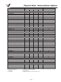
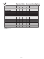
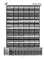
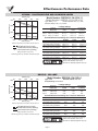
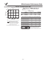
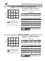
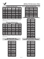
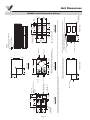
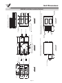
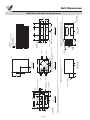
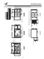
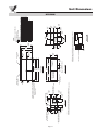
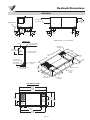
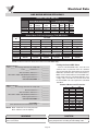
Product Data Manual
HRV600i • HRV700i • HRV1200i • HRV2000i/e
HRV2000e
Table of Contents
Physical Data - Nomenclature Options . . . . . . . . . . . . . . . . . . . . . . . . . . . . . . . . . . . . . . . . . . . . . 3
Effectiveness Performance Data . . . . . . . . . . . . . . . . . . . . . . . . . . . . . . . . . . . . . . . . . . . . . . . . . 6
Airflow Performance Data . . . . . . . . . . . . . . . . . . . . . . . . . . . . . . . . . . . . . . . . . . . . . . . . . . . . . . 10
Unit Dimensions . . . . . . . . . . . . . . . . . . . . . . . . . . . . . . . . . . . . . . . . . . . . . . . . . . . . . . . . . . . . . 12
Roofcurb Dimensions . . . . . . . . . . . . . . . . . . . . . . . . . . . . . . . . . . . . . . . . . . . . . . . . . . . . . . . . . 19
Electrical Data . . . . . . . . . . . . . . . . . . . . . . . . . . . . . . . . . . . . . . . . . . . . . . . . . . . . . . . . . . . . . . . 20
Controls Data . . . . . . . . . . . . . . . . . . . . . . . . . . . . . . . . . . . . . . . . . . . . . . . . . . . . . . . . . . . . . . . 21
Options . . . . . . . . . . . . . . . . . . . . . . . . . . . . . . . . . . . . . . . . . . . . . . . . . . . . . . . . . . . . . . . . . . . . 23
Due to ongoing research and development, Venmar CES Inc. reserves the right to modify
specifications and dimensions without prior notice.
Page 2
Physical Data - Nomenclature Options
UNIT NOMENCLATURE OPTIONS
FROST CONTROL
Recirculation
Exhaust only
Non defrost
Non defrost, no wall control compatibility
Preheat frost prevention
VOLTAGE/SPEED
208-230 VAC/1/60 - 1 Speed
208-230 VAC/3/60 - 1 Speed
460 VAC/3/60 - 1 Speed
575 VAC/3/60 - 1 Speed
120 VAC/1/60 - 2 Speed
208-230 VAC/1/60 - 2 Speed
ENERGY RECOVERY
Polypropylene core
Aluminum core
HM core
INTERNAL PROTECTION
1" insulation, single wall (R4)
1" insulation, double wall (R4)
Corrosion resistant R4, double wall (1")
SENSOR CONTACTS
Dirty filter contacts
No contacts
EXTERNAL FINISH
Galvanized (non painted)
Grey prepaint (galvanized)
White prepaint (galvanized)
Corrosion resistant package
OUTSIDE AIR DAMPER
Non insulated motorized
Insulated motorized
Insulated spring return
No damper
EXHAUST AIR DAMPER
Backdraft
Non insulated motorized
Insulated motorized
No damper
DOOR FASTENERS
Standard blower/filter access
Deluxe blower/filter access
Deluxe filter doors only
EXTERNAL DISCONNECT
Fused disconnect switch
Non fused disconnect switch
No disconnect switch
Legend:
B - Included in base unit
O - Optional
A - Accessory
600i
INDOOR UNITS
700i
1200i
B
1, 2, A
B
1, 2, A
B
1, 2, A
B
B
B
B
O
O
B
B
O
O
O
O
O
O
O
2000i
O
O
O
B
1, 2, A
B/3
O
O
O
B
O
O
B
B
O
B
B
B
O
O
O
B
B
O
O
O
B
A
A
B
O
B
B
B
O
O
B
1 - Call Factory for more information
2 - Duct-mounted
3 - Requires a neutral wire to be run with L1 & L2
Page 3
B/3
O
O
O
B
O
O
B
O
O
B
A
O
O
O
B
O/3
B
A
2000e
O/3
B
B
OUTDOOR UNITS
B
O
O
O
B
B
O
O
O
O
B
O
O
O
B
B
O
O
O
B
Physical Data - Nomenclature Options
UNIT NOMENCLATURE OPTIONS
HOODS
Intake/exhaust hoods
No hoods
SUPPLY DISCHARGE
End supply discharge
Down supply discharge
RETURN AIR
End return air inlet
Bottom return air inlet
FILTERS
Supply AL mesh pre-filter
Supply MEF (30%) DSE
Supply HEF (80 - 85%) DSE
Exhaust MEF (30%) DSE
Supply washable foam 20ppm
Exhaust washable foam 20ppm
ACCESS DOOR
Standard door
Reverse door
LOW SPEED
Reduced low speed
Normal low speed
Legend:
B - Included in base unit
O - Optional
600i
INDOOR UNITS
700i
1200i
2000i
B
B
B
B
B
B
B
B
O
O
O
B
B
B
B
B
B
B
O
B
O
B
B
B
B
O
B
B
Page 4
B
B
O
O
B
B
OUTDOOR UNITS
2000e
O
B
O
B
O
B
O
B
O
B
B
O
B
O
O
Physical Data
FANS
Model Name
Supply Type
Wheel Type
Wheel Size (Inches)
Wheel Size [mm]
Bearing
Housing
Shaft [mm]
Exhaust Type
Wheel Type
Wheel Size (Inches)
Wheel Size [mm]
Bearing
Housing
Shaft [mm]
HRV600i
HRV700i
Type
Size (Inches)
Size [mm]
Flat Plate Material
Model Name
Belt drive
Forward curved
12Ø x 7
305Ø x 178
Ball sealed
Resilient rings
Cold rolled
1" [25] keyed
Belt drive
Forward curved
12Ø x 7
305Ø x 178
Ball sealed
Resilient rings
Cold rolled
1" [25] keyed
Belt drive
Forward curved
12Ø x 7
305Ø x 178
Ball sealed
Resilient rings
Cold rolled
1" [25] keyed
Belt drive
Forward curved
12Ø x 9
305Ø x 229
Ball sealed
Resilient rings
Cold rolled
1" [25] keyed
HRV600i
HRV700i
HRV1200i
HRV2000i
HRV2000e
HRV2000i
HRV2000e
HRV600i
Type (Primary)
Washable foam
Size (Inches)
13 x 11 x 1
Size [mm]
[330 x 279 x 25]
Number Per Airstream
2
Type (Secondary)
MEF
Size (Inches)
13 x 11.25 x 2
Size [mm]
[330 x 286 x 51]
Number Per Airstream
2
Flat plate
23 x 23 x 19
[584 x 584 x 483]
Polypropylene
Page 7
Flat plate
12 x 12 x 39
[305 x 305 x 991]
Polypropylene,
Aluminum or HM
Page 8
HRV700i
HRV1200i
Washable foam
22.25 x 19 x 1
[572 x 483 x 25]
1 (Supply)
MEF
22.625 x 19.25 x 1.75
[575 x 489 x 51]
1
Washable foam
13 x 11 x 1
[330 x 279 x 25]
3
MEF
13 x 11.25 x 2
[330 x 286 x 51]
3
HRV700i
HRV1200i
WEIGHT (WITH RECIRCULATION DEFROST)
Model Name
HRV600i
Net Core Weight Maximum
Polypropylene Core
197 lbs [90kg]
Aluminum Core
204 lbs [93kg]
HM Core
208 lbs [95kg]
Shipping Weight
add 40 lbs [18kg]
HRV600i
Net Core Weight Maximum
Polypropylene Core
148 lbs [67kg]
Aluminum Core
155 lbs [70kg]
HM Core
159 lbs [72kg]
Shipping Weight
add 40 lbs [18kg]
Unit
HRV600i
Flat plate
Flat plate
15 x 15 x 46
15 x 15 x 46
[381 x 381 x 1168] [381 x 381 x 1168]
Polypropylene,
Polypropylene,
Aluminum or HM Aluminum or HM
Page 9
Page 9
MEF
12 x 24 x
[305 x 610 x
2
HEF
12 x 24 x
[305 x 610 x
2
4
102]
4
102]
HRV2000i
MEF
12 x 24 x
[305 x 610 x
2
HEF
12 x 24 x
[305 x 610 x
2
4
102]
HRV2000e
247 lbs [112kg]
257 lbs [117kg]
264 lbs [120kg]
add 40 lbs [18kg]
700 lbs [318kg]
730 lbs [332kg]
730 lbs [332kg]
add 50 lbs [23kg]
730 lbs [332kg]
760 lbs [345kg]
760 lbs [345kg]
add 30 lbs [14kg]
HRV700i
HRV1200i
HRV2000i
HRV2000e
N/A
N/A
N/A
N/A
186 lbs [85kg]
196 lbs [89kg]
203 lbs [92kg]
add 40 lbs [18kg]
700 lbs [318kg]
730 lbs [332kg]
730 lbs [332kg]
add 50 lbs [23kg]
UNIT AIRFLOW TABLE (CFM X 100)
730 lbs [332kg]
760 lbs [345kg]
760 lbs [345kg]
add 30 lbs [14kg]
4 6 8 10 12 14 16 18 20 22 24 26 28 30 32 34 36 38 40 42 44 46
HRV700i
HRV1200i
HRV2000i/e
4
102]
210 lbs [95kg]
N/A
N/A
250 lbs [114kg]
WEIGHT (WITH EXHAUST ONLY DEFROST)
Model Name
HRV2000e
Direct drive
Forward curved
7Ø x 6 (two)
178Ø x 152
Sleeve
Direct drive
Cold rolled
1/2" [13] keyed
Direct drive
Forward curved
7Ø x 6
178Ø x 152
Sleeve
Direct drive
Cold rolled
1/2" [13] keyed
Flat plate
12 x 12 x 26
[305 x 305 x 660]
Polypropylene,
Aluminum or HM
Flat Plate Performance
Page 6
FILTERS
HRV2000i
Direct drive
Forward curved
9Ø x 7
229Ø x 178
Sleeve
Direct drive
Cold rolled
1/2" [13]
Direct drive
Forward curved
9Ø x 7
229Ø x 178
Sleeve
Direct drive
Cold rolled
1/2" [13]
HEAT RECOVERY MODULE
Model Name
HRV1200i
Direct drive
Forward curved
7Ø x 6
178Ø x 152
Sleeve
Direct drive
Cold rolled
1/2" [13]
Direct drive
Forward curved
7Ø x 6
178Ø x 152
Sleeve
Direct drive
Cold rolled
1/2" [13]
For airflows higher than 2800 cfm, see the HRV3000i/e to HRV10000i/e PDM (PN 216004) or
the EnergyPack® PDM (PN 500003428) in your Venmar CES Binder/Catalog or online at www.venmarces.com.
Page 5
Effectiveness Performance Data
HRV600i - POLYPROPYLENE AND ALUMINUM CORES
Effectiveness
94
70%
165
Airflow (L/s)
236
307
378
Model Number: PHE500-13.1H-12S-0.11
Model Number: AHE500-13.1H-12S-0.14T
Type: Plate (Plate)
Nominal Airflow: 200 (200) scfm
Pressure Drop: 0.22 (0.09) inches
50%
Leakage Ratings
Pressure
Differential
Test 1: -5.00 (-3.00) inches
Test 2: 0.00 (0.00) inches
Test 3: 5.00 (3.00) inches
30%
10%
200
350
500
650
Airflow (cfm)
800
Based on equal amounts of outdoor air and return air.
n/a
Total Effectiveness (Cooling)
Sensible Effectiveness (Heating)
Latent Effectiveness (Heating)
Ratings outside the scope of the
AHRI Energy Recovery Ventilation Certification Program.
EATR
0% (0%)
0% (0%)
0% (0%)
OACF
1.00 (1.00)
1.00 (1.00)
1.00 (1.00)
Purge Angle
or Setting
N/A (N/A)
N/A (N/A)
N/A (N/A)
Thermal Effectiveness Ratings at 0" Pressure Differential
100% Airflow Heating Condition:
75% Airflow Heating Condition:
100% Airflow Cooling Condition:
75% Airflow Cooling Condition:
Sensible
64% (60%)
66% (66%)
55% (54%)
60% (59%)
Latent
0% (0%)
0% (0%)
0% (0%)
0% (0%)
Total
42% (39%)
44% (43%)
21% (21%)
23% (23%)
100% Airflow Heating Condition:
75% Airflow Heating Condition:
100% Airflow Cooling Condition:
75% Airflow Cooling Condition:
Net Sensible
64% (60%)
66% (66%)
55% (54%)
60% (59%)
Net Latent
0% (0%)
0% (0%)
0% (0%)
0% (0%)
Net Total
42% (39%)
44% (43%)
21% (21%)
23% (23%)
Energy recovery component is certified by
AHRI to AHRI Standard 1060. Actual
performance in packaged equipment may vary.
HRV600i - HM CORE
Effectiveness
94
90%
165
Airflow (L/s)
236
307
378
Model Number: EPE5000-13H-12S-0.1
Type: Plate
Nominal Airflow: 200 scfm
Pressure Drop: 0.28 inches
Leakage Ratings
70%
Test 1:
Test 2:
Test 3:
50%
Pressure
Differential
-0.50 inches
0.00 inches
0.50 inches
EATR
2.0%
0.5%
0.0%
OACF
1.00
1.01
1.02
Purge Angle
or Setting
N/A
N/A
N/A
Thermal Effectiveness Ratings at 0" Pressure Differential
30%
200
350
500
650
Airflow (cfm)
800
Based on equal amounts of outdoor air and return air.
Total Effectiveness (Cooling)
Sensible Effectiveness (Heating)
Latent Effectiveness (Heating)
Ratings outside the scope of the
AHRI Energy Recovery Ventilation Certification Program.
100% Airflow Heating Condition:
75% Airflow Heating Condition:
100% Airflow Cooling Condition:
75% Airflow Cooling Condition:
Sensible
60%
65%
60%
65%
Latent
50%
55%
38%
45%
Total
56%
61%
47%
53%
100% Airflow Heating Condition:
75% Airflow Heating Condition:
100% Airflow Cooling Condition:
75% Airflow Cooling Condition:
Net Sensible
60%
65%
60%
65%
Net Latent
50%
55%
38%
45%
Net Total
56%
61%
47%
53%
Energy recovery component is certified by
AHRI to AHRI Standard 1060. Actual
performance in packaged equipment may vary.
Page 6
Effectiveness Performance Data
HRV700i - POLYPROPYLENE CORE
Effectiveness
142
80%
201
Airflow (L/s)
260
319
378
Model Number: PHE500-19H-23S-0.12
Type: Plate
Pressure Drop: 0.25 inches
Nominal Airflow: 400 scfm
Leakage Ratings
60%
Test 1:
Test 2:
Test 3:
40%
Pressure
Differential
-5.00 inches
0.00 inches
5.00 inches
EATR
0%
0%
0%
OACF
1.00
1.00
1.00
Purge Angle
or Setting
N/A
N/A
N/A
Thermal Effectiveness Ratings at 0" Pressure Differential
20%
300
425
550
675
Airflow (cfm)
800
Based on equal amounts of outdoor air and return air.
n/a
Total Effectiveness (Cooling)
Sensible Effectiveness (Heating)
Latent Effectiveness (Heating)
Ratings outside the scope of the
AHRI Energy Recovery Ventilation Certification Program.
100% Airflow Heating Condition:
75% Airflow Heating Condition:
100% Airflow Cooling Condition:
75% Airflow Cooling Condition:
Sensible
76%
79%
71%
74%
Latent
0%
0%
0%
0%
Total
50%
52%
27%
29%
100% Airflow Heating Condition:
75% Airflow Heating Condition:
100% Airflow Cooling Condition:
75% Airflow Cooling Condition:
Net Sensible
76%
79%
71%
74%
Net Latent
0%
0%
0%
0%
Net Total
50%
52%
27%
29%
Energy recovery component is certified by
AHRI to AHRI Standard 1060. Actual
performance in packaged equipment may vary.
Page 7
Effectiveness Performance Data
HRV1200i - POLYPROPYLENE AND ALUMINUM CORES
Effectiveness
189
70%
307
Airflow (L/s)
472
590
661
Model Number: PHE500-13.1H-12S-0.11
Model Number: AHE500-13.1H-12S-0.14T
Type: Plate (Plate)
Nominal Airflow: 200 (200) scfm
Pressure Drop: 0.22 (0.09) inches
50%
Leakage Ratings
Test 1:
Test 2:
Test 3:
30%
10%
400
650
1000
1250
Airflow (cfm)
1400
Based on equal amounts of outdoor air and return air.
n/a
Total Effectiveness (Cooling)
Sensible Effectiveness (Heating)
Latent Effectiveness (Heating)
Ratings outside the scope of the
AHRI Energy Recovery Ventilation Certification Program.
Pressure
Differential
-5.00 (-3.00) inches
0.00 (0.00) inches
5.00 (3.00) inches
EATR
0% (0%)
0% (0%)
0% (0%)
OACF
1.00 (1.00)
1.00 (1.00)
1.00 (1.00)
Purge Angle
or Setting
N/A (N/A)
N/A (N/A)
N/A (N/A)
Thermal Effectiveness Ratings at 0" Pressure Differential
100% Airflow Heating Condition:
75% Airflow Heating Condition:
100% Airflow Cooling Condition:
75% Airflow Cooling Condition:
Sensible
64% (60%)
66% (66%)
55% (54%)
60% (59%)
Latent
0% (0%)
0% (0%)
0% (0%)
0% (0%)
Total
42% (39%)
44% (43%)
21% (21%)
23% (23%)
100% Airflow Heating Condition:
75% Airflow Heating Condition:
100% Airflow Cooling Condition:
75% Airflow Cooling Condition:
Net Sensible
64% (60%)
66% (66%)
55% (54%)
60% (59%)
Net Latent
0% (0%)
0% (0%)
0% (0%)
0% (0%)
Net Total
42% (39%)
44% (43%)
21% (21%)
23% (23%)
Energy recovery component is certified by
AHRI to AHRI Standard 1060. Actual
performance in packaged equipment may vary.
HRV1200I - HM CORE
Effectiveness
94
90%
165
Airflow (L/s)
236
307
378
Model Number: EPE5000-13H-12S-0.1
Type: Plate
Nominal Airflow: 200 scfm
Pressure Drop: 0.28 inches
Leakage Ratings
70%
Test 1:
Test 2:
Test 3:
50%
Pressure
Differential
-0.50 inches
0.00 inches
0.50 inches
EATR
2.0%
0.5%
0.0%
OACF
1.00
1.01
1.02
Purge Angle
or Setting
N/A
N/A
N/A
Thermal Effectiveness Ratings at 0" Pressure Differential
30%
400
600
800
1000
Airflow (cfm)
1200
Based on equal amounts of outdoor air and return air.
Total Effectiveness (Cooling)
Sensible Effectiveness (Heating)
Latent Effectiveness (Heating)
Ratings outside the scope of the
AHRI Energy Recovery Ventilation Certification Program.
100% Airflow Heating Condition:
75% Airflow Heating Condition:
100% Airflow Cooling Condition:
75% Airflow Cooling Condition:
Sensible
60%
65%
60%
65%
Latent
50%
55%
38%
45%
Total
56%
61%
47%
53%
100% Airflow Heating Condition:
75% Airflow Heating Condition:
100% Airflow Cooling Condition:
75% Airflow Cooling Condition:
Net Sensible
60%
65%
60%
65%
Net Latent
50%
55%
38%
45%
Net Total
56%
61%
47%
53%
Energy recovery component is certified by
AHRI to AHRI Standard 1060. Actual
performance in packaged equipment may vary.
Page 8
Effectiveness Performance Data
HRV2000i/e - POLYPROPYLENE AND ALUMINUM CORES
Effectiveness
472
70%
684
Airflow (L/s)
897
1109
1322
Model Number: PHE500-15.4H-15.3S-0.11
Model Number: AHE500-15.4H-15S-0.14
Type: Plate (Plate)
Nominal Airflow: 530 (530) scfm
Pressure Drop: 0.86 (0.30) inches
50%
Leakage Ratings
Test 1:
Test 2:
Test 3:
30%
10%
1000
1450
1900
2350
Airflow (cfm)
2800
Based on equal amounts of outdoor air and return air.
n/a
Total Effectiveness (Cooling)
Sensible Effectiveness (Heating)
Latent Effectiveness (Heating)
Ratings outside the scope of the
AHRI Energy Recovery Ventilation Certification Program.
Pressure
Differential
-5.00 (-3.00) inches
0.00 (0.00) inches
5.00 (3.00) inches
EATR
0% (0%)
0% (0%)
0% (0%)
OACF
1.00 (1.00)
1.00 (1.00)
1.00 (1.00)
Purge Angle
or Setting
N/A (N/A)
N/A (N/A)
N/A (N/A)
Thermal Effectiveness Ratings at 0" Pressure Differential
100% Airflow Heating Condition:
75% Airflow Heating Condition:
100% Airflow Cooling Condition:
75% Airflow Cooling Condition:
Sensible
58% (52%)
63% (58%)
49% (46%)
55% (52%)
Latent
0% (0%)
0% (0%)
0% (0%)
0% (0%)
Total
38% (34%)
42% (38%)
19% (18%)
21% (20%)
100% Airflow Heating Condition:
75% Airflow Heating Condition:
100% Airflow Cooling Condition:
75% Airflow Cooling Condition:
Net Sensible
58% (52%)
63% (58%)
49% (46%)
55% (52%)
Net Latent
0% (0%)
0% (0%)
0% (0%)
0% (0%)
Net Total
38% (34%)
42% (38%)
19% (18%)
21% (20%)
Energy recovery component is certified by
AHRI to AHRI Standard 1060. Actual
performance in packaged equipment may vary.
HRV2000i/e - HM CORE
Effectiveness
472
70%
684
Airflow (L/s)
897
1109
1322
Model Number: EPE5000-15.3H-15S-0.1
Type: Plate
Nominal Airflow: 530 scfm
Pressure Drop: 0.75 inches
Leakage Ratings
50%
Test 1:
Test 2:
Test 3:
30%
10%
1000
Pressure
Differential
-0.50 inches
0.00 inches
0.50 inches
EATR
1.0%
0.5%
0.0%
OACF
1.00
1.01
1.01
Purge Angle
or Setting
N/A
N/A
N/A
Thermal Effectiveness Ratings at 0" Pressure Differential
1450
1900
2350
Airflow (cfm)
2800
Based on equal amounts of outdoor air and return air.
Total Effectiveness (Cooling)
Sensible Effectiveness (Heating)
Latent Effectiveness (Heating)
Ratings outside the scope of the
AHRI Energy Recovery Ventilation Certification Program.
100% Airflow Heating Condition:
75% Airflow Heating Condition:
100% Airflow Cooling Condition:
75% Airflow Cooling Condition:
Sensible
54%
59%
54%
59%
Latent
44%
49%
30%
37%
Total
51%
55%
39%
45%
100% Airflow Heating Condition:
75% Airflow Heating Condition:
100% Airflow Cooling Condition:
75% Airflow Cooling Condition:
Net Sensible
54%
59%
54%
59%
Net Latent
44%
49%
30%
37%
Net Total
51%
55%
39%
45%
Energy recovery component is certified by
AHRI to AHRI Standard 1060. Actual
performance in packaged equipment may vary.
Page 9
Airflow Performance Data
HRV600i AIRFLOW (CFM)
ESP
0.00
0.10
0.20
0.30
0.40
0.50
0.60
0.70
0.80
0.90
1.00
Low
650
635
611
595
570
544
517
488
447
322
256
Reduced
Low
474
456
447
442
428
418
403
382
354
311
253
Medium
734
707
686
657
635
603
579
544
507
447
291
Reduced
Medium
574
569
557
546
528
510
478
452
416
376
332
HRV700i AIRFLOW (CFM)
High
791
764
735
705
682
650
625
589
542
491
322
NOTE: Medium tap can be installed by exchanging the low tap for
medium (see wiring diagram). The standard unit has only two speeds
available to the user. Reduced low and reduced medium speeds must be
ordered as options.
HRV1200i AIRFLOW (CFM)
ESP
0.00
0.10
0.20
0.30
0.40
0.50
0.60
0.70
0.80
0.90
1.00
Low
1110
1080
1029
987
942
896
834
767
695
596
500
Reduced
Low
N/A
N/A
775
755
745
714
670
647
586
518
422
Medium
1195
1157
1105
1064
1007
963
900
832
759
656
534
Reduced
Medium
936
911
894
885
868
832
785
725
670
599
503
High
1254
1214
1158
1114
1069
1022
955
883
806
673
568
NOTE: Medium tap can be installed by exchanging the low tap for
medium (see wiring diagram). The standard unit has only two speeds
available to the user. Reduced low and reduced medium speeds must be
ordered as options.
PRESSURE DROP FOR
EXHAUST HOOD WITH DAMPER
Airflow
(cfm)
1200
1300
1400
1500
1600
1700
1800
1900
2000
2100
2200
2300
2400
2500
2600
2700
2800
Resistance
(in. wg.)
0.30
0.35
0.40
0.46
0.51
0.56
0.61
0.68
0.71
0.76
0.81
0.86
0.91
0.96
1.01
1.06
1.11
ESP
Low
0.00
0.10
0.20
0.30
0.40
0.50
0.60
0.70
0.80
0.90
869
817
767
692
609
531
441
296
190
118
PRESSURE DROP FOR H.E. FILTERS
Airflow
(cfm)
800
900
1000
1100
1200
1300
1400
1500
1600
1700
1800
1900
2000
2100
2200
2300
2400
2500
2600
2700
2800
Resistance
(in. wg.)
0.16
0.19
0.22
0.25
0.28
0.30
0.33
0.36
0.40
0.45
0.49
0.54
0.59
0.63
0.68
0.72
0.77
0.81
0.85
0.90
0.95
PRESSURE DROP FOR
EXHAUST HOOD WITHOUT DAMPER
Airflow
(cfm)
Page 10
High
430
420
416
395
356
300
242
174
109
N/A
1200
1300
1400
1500
1600
1700
1800
1900
2000
2100
2200
2300
2400
2500
2600
2700
2800
Resistance
(in. wg.)
0.00
0.04
0.07
0.11
0.14
0.17
0.21
0.24
0.28
0.31
0.35
0.38
0.42
0.45
0.48
0.52
0.55
Airflow Performance Data
HRV2000i SUPPLY AND EXHAUST AIRFLOW PERFORMANCE
HRV2000e SUPPLY AIRFLOW PERFORMANCE
Airflow
(cfm)
1200
1300
1400
1500
1600
1700
1800
1900
2000
2100
2200
2300
2400
2500
2600
2700
2800
0.0
RPM BHP
597 0.19
637 0.24
676 0.28
713 0.34
748 0.40
785 0.47
818 0.55
853 0.63
892 0.73
925 0.83
960 0.94
995 1.03
1029 1.19
1062 1.32
1095 1.46
1129 1.62
1161 1.79
0.2
RPM BHP
695 0.24
729 0.29
762 0.34
794 0.41
826 0.47
858 0.55
889 0.62
923 0.72
957 0.81
989 0.92
1021 1.03
1054 1.16
1086 1.29
1117 1.44
1148 1.58
1179 1.74
1210 1.90
0. 4
RPM BHP
784 0.30
813 0.35
842 0.40
871 0.47
899 0.54
928 0.62
957 0.70
988 0.80
1019 0.90
1050 1.02
1080 1.13
1110 1.26
1140 1.39
1170 1.54
1199 1.69
1229 1.86
1259 2.03
IMPORTANT NOTE: Pressure Drop
0.6
RPM BHP
867 0.36
892 0.42
917 0.47
942 0.54
967 0.61
994 0.70
1020 0.78
1050 0.89
1079 0.99
1107 1.11
1135 1.22
1164 1.36
1193 1.49
1221 1.65
1249 1.80
1278 1.98
1306 2.15
0.8
RPM BHP
944 0.42
967 0.48
989 0.54
1012 0.62
1034 0.69
1058 0.78
1082 0.86
1109 0.97
1136 1.07
1163 1.20
1189 1.32
1216 1.46
1243 1.60
1270 1.76
1297 1.91
1325 2.09
1352 2.27
1.0
RPM BHP
1018 0.48
1037 0.55
1056 0.61
1077 0.69
1097 0.77
1119 0.86
1141 0.94
1166 1.05
1191 1.16
1216 1.29
1241 1.41
1267 1.56
1293 1.70
1319 1.86
1344 2.02
1370 2.21
1396 2.39
1.2
RPM BHP
1090 0.55
1106 0.62
1121 0.69
1140 0.77
1158 0.85
1179 0.94
1199 1.03
1222 1.14
1245 1.25
1269 1.38
1292 1.51
1317 1.66
1341 1.80
1365 1.97
1389 2.13
1415 2.32
1440 2.51
1.4
RPM BHP
1158 0.61
1172 0.69
1185 0.77
1201 0.85
1217 0.93
1236 1.03
1254 1.12
1276 1.18
1297 1.23
1319 1.42
1341 1.61
1364 1.76
1387 1.91
1411 2.08
1434 2.25
1459 2.44
1483 2.63
1.6
HP
RPM BHP Fan Pulley
1222 0.68
1/2
1235 0.76
1247 0.84
3/4
1260 0.93
1273 1.02
1.0
1291 1.12
1308 1.22
1.5
1328 1.34
1348 1.45
2.0
1369 1.58
1389 1.71
3.0
1411 1.87
1433 2.02
1456 2.19
1478 2.36
1501 2.56
1524 2.75
When the high efficiency filter option is used, filter pressure drop must be added to the ESP of the system. Added pressure drop values are listed
in the "Pressure Drop For H.E. Filters" table on the previous page.
HRV2000e EXHAUST AIRFLOW PERFORMANCE
A ir f lo w
(cfm)
1200
1300
1400
1500
1600
1700
1800
1900
2000
2100
2200
2300
2400
2500
2600
2700
2800
0.0
RPM BHP
591 0.16
630 0.20
667 0.24
701 0.29
734 0.34
769 0.40
799 0.46
832 0.53
868 0.61
898 0.69
931 0.79
963 0.88
994 0.99
1024 1.10
1053 1.22
1085 1.35
1113 1.48
0 .2
RPM BHP
700 0.21
732 0.26
763 0.30
793 0.36
822 0.41
851 0.48
880 0.54
912 0.62
943 0.69
972 0.79
1001 0.88
1030 0.99
1059 1.09
1087 1.21
1115 1.32
1143 1.46
1171 1.59
0.4
RPM BHP
805 0.27
829 0.32
853 0.36
878 0.42
903 0.48
945 0.55
986 0.61
999 0.70
1012 0.78
1040 0.88
1067 0.97
1095 1.08
1122 1.18
1148 1.31
1174 1.43
1201 1.57
1227 1.71
IMPORTANT NOTE: Pressure Drop
0 .6
RPM BHP
899 0.33
920 0.38
941 0.43
962 0.49
982 0.55
1004 0.62
1026 0.69
1053 0.78
1079 0.86
1104 0.96
1129 1.06
1155 1.17
1181 1.28
1206 1.41
1231 1.54
1256 1.68
1281 1.82
0.8
RPM BHP
984 0.39
1004 0.45
1023 0.50
1041 0.57
1059 0.63
1078 0.70
1097 0.77
1120 0.86
1142 0.95
1166 1.05
1189 1.15
1214 1.27
1238 1.38
1262 1.51
1285 1.64
1309 1.79
1333 1.94
1. 0
RPM BHP
1061 0.45
1080 0.51
1099 0.57
1116 0.64
1132 0.70
1150 0.78
1167 0.86
1187 0.95
1206 1.04
1227 1.15
1247 1.25
1270 1.37
1293 1.49
1316 1.62
1338 1.75
1361 1.90
1383 2.05
1.2
RPM BHP
1133 0.52
1152 0.58
1170 0.64
1186 0.71
1201 0.78
1217 0.87
1233 0.95
1301 1.04
1369 1.13
1337 1.24
1305 1.35
1326 1.47
1346 1.59
1367 1.73
1388 1.86
1410 2.02
1432 2.17
1. 4
RPM BHP
1200 0.58
1218 0.65
1235 0.72
1251 0.80
1266 0.87
1281 0.95
1296 1.03
1313 1.13
1330 1.23
1347 1.34
1363 1.45
1381 1.58
1398 1.70
1419 1.84
1439 1.98
1460 2.14
1480 2.29
1.6
RPM BHP
1263 0.65
1281 0.72
1298 0.79
1313 0.87
1328 0.95
1343 1.04
1357 1.12
1373 1.23
1389 1.33
1404 1.44
1419 1.55
1436 1.68
1452 1.81
1470 1.95
1487 2.09
1507 2.25
1527 2.41
1.8
RPM BHP
1322 0.72
1340 0.80
1357 0.87
1372 0.95
1386 1.03
1401 1.13
1415 1.22
1431 1.33
1446 1.43
1460 1.55
1474 1.66
1489 1.79
1504 1.92
1520 2.07
1535 2.21
1554 2.37
1572 2.53
2.0
RPM BHP
1378 0.79
1396 0.87
1413 0.95
1428 1.04
1442 1.12
1456 1.22
1470 1.31
1485 1.42
1500 1.53
1514 1.65
1527 1.77
1542 1.91
1556 2.04
1570 2.19
1584 2.33
1600 2.49
1616 2.65
HP
Fan Pulley
1/2
3/4
1.0
1.5
2.0
3.0
Pressure drop for exhaust hood (with or without damper) must be added to the ESP of the system. Added pressure drop values are listed in the
"Pressure Drop For Exhaust Hood With Damper" and "Pressure Drop For Exhaust Hood Without Damper" tables on the previous page.
Page 11
Page 12
10.005"
[254]
LEFT VIEW
SUPPLY AIR
OPENING
EXHAUST AIR
OPENING
14.000"
[356]
CONTROL BOX
ACCESS
LOW VOLTAGE
TERMINAL STRIPS
SUPPLY AIR
EXHAUST AIR
LINE VOLTAGE IN
4.028"
[102]
A
5.859" [149]
C
5.125"
[130]
D
RETURN AIR
OUTDOOR AIR
FRONT VIEW
NOTE: For units with the reversed door option, interior
components will appear as a mirror image of the above diagram.
19.207"
[488]
34.000"
[864]
TOP VIEW
13.375"
[340]
B
B
A
B
7.705"
[196]
14.103"
[358]
RETURN AIR
OPENING
OUTDOOR AIR
OPENING
14.000"
[356]
23.500"
[597]
RIGHT VIEW
CONDENSATE DRAIN
4.000"
[102]
24.500"
[622]
2.750"
[70]
STRAP MOUNTING
LOCATION
CONNECTION TABLE
CONNECTION SIZES
Line voltage in
14 gauge wire nut
Condensate drain fitting (2x)
3/4" mpt
HRV600i
ALUMINUM CORE
HM CORE
POLY CORE
PTS LBS Kg
PTS LBS Kg
PTS LBS Kg
17
38
18
19
40
41
A
A
A
25
26
27
B
12
12
11
B
B
C
24
C
25
C
25
52
55
56
33
D
D
D
15
15
16
34
35
70 TOTAL 159
72
67 TOTAL 155
TOTAL 148
Direction of airflow
Center of gravity
CONTROL PLATE
12.000"
[305]
FRONT VIEW
NOTE: A minimum of 12.000" [305] clearance from any
obstruction is required for removal of the control box.
HEAT RECOVERY CORE
ACCESS DOOR
15.000"
[381]
RIGHT VIEW
REVERSED
DOOR OPTION
NOTE: A minimum of 15.000" [381] clearance from any obstruction is required for
removal of heat recovery cores, fans, etc.
The access door can be removed from the cabinet with only 2.000" [51] of clearance.
8.000"
[203]
8.000"
[203]
6.500"
[165]
NOTE: This model has a damper located on the outdoor intake connection. This damper will close during a frost control cycle or when the unit is placed in the 'OFF' position with power maintained to the unit. This damper is not designed as a
backdraft damper and will remain open if power is disconnected from the unit for any reason.
REVERSED
DOOR OPTION
3.535" [90]
8.000"
[203]
4.000" [102]
8.000"
[203]
4.000"
[102]
28.005"
[711]
12.005"
[305]
A
NOTES:
Dimensions in [ ] are millimeters
HRV600i (with Exhaust Only Defrost)
Unit Dimensions
3.530"
[90]
8.000"
[203]
4.000"
24.500" [102]
[622]
8.000"
[203]
1.750"
[44]
4.000" [102]
LEFT VIEW
EXHAUST AIR
LINE VOLTAGE IN
CONTROL BOX
Page 13
5.125"
130]
For Recirc Defrost Only
FRONT VIEW
12.000"
[305]
FRONT VIEW
ACCESS
DOOR
B
A
CONDENSATE DRAIN
7.100"
[180]
RIGHT VIEW
14.100"
[358]
RETURN AIR
OPENING
OUTDOOR AIR
OPENING
14.000"
[356]
1.750"
[44]
8.000"
[203]
4.000"
[102]
8.000"
[203]
15.000"
[381]
RIGHT VIEW
REVERSED
DOOR OPTION
NOTE: A minimum of 15.000" [381] clearance from any obstruction is required for removal
of heat recovery cores, fans, etc.
The access door can be removed from cabinet with only 2.000" [51] of clearance.
B
ACCESS DOOR
RETURN AIR
OUTDOOR AIR
STRAP MOUNTING
LOCATION
HEAT
RECOVERY
CORE
NOTE:
For units with the reversed door option, interior components will appear
as a mirror image of the above diagram.
19.207"
[488]
34.000"
[864]
49.550"
[1,259]
NOTE: A minimum of 12.000" [305] clearance from any obstruction
is required for removal of the control box.
SUPPLY AIR
DRY CONTACTS
A
2.750"
[70]
CONTROL PANEL
REVERSED DOOR OPTION
SUPPLY AIR
OPENING
EXHAUST AIR
OPENING
14.000"
[356]
28.120"
[714]
CONNECTION TABLE
CONNECTION SIZES
Line voltage in
14 gauge wire nut
Condensate drain fitting (2x)
3/4" mpt
600i (with Recirculation Defrost)
197 LBS [90 kg]
POLY CORE
ALUMINUM CORE 204 LBS [93 kg]
208 LBS [95 kg]
HM CORE
NOTE: Dimensions in [ ] are millimeters
HRV600i (with Recirculation Defrost)
Unit Dimensions
Page 14
LEFT VIEW
SUPPLY AIR
OPENING
EXHAUST AIR
OPENING
20.000"
[508]
11.325"
[288]
A
CONTROL BOX
ACCESS
SUPPLY AIR
EXHAUST AIR
LINE VOLTAGE IN
LOW VOLTAGE
TERMINAL STRIPS
4.028"
[102]
5.715"
[145]
C
5.125"
[130]
D
RETURN AIR
OUTDOOR AIR
FRONT VIEW
B
A
B
RETURN AIR
OPENING
9.878"
[251]
RIGHT VIEW
20.000"
[508]
OUTDOOR AIR
OPENING
20.000"
[508]
CONNECTION SIZES
14 gauge wire nut
3/4" mpt
CONDENSATE DRAIN
ACCESS DOOR
4.000"
[102]
2.750"
[70]
11.000"
[279]
Line voltage in
Condensate drain fitting (2x)
CONNECTION TABLE
HRV1200i
HM CORE
ALUMINUM CORE
POLY CORE
PTS LBS Kg
PTS LBS Kg
PTS LBS Kg
25
54
27
26
59
57
A
A
A
39
43
41
B
20
19
B
18
B
C
27
26
C
25
C
59
57
54
39
D
D
D
20
19
18
43
41
94
90 TOTAL 204
TOTAL 186
86 TOTAL 196
Dimensions in [ ] are millimeters
Center of gravity
Direction of airflow
STRAP MOUNT
LOCATION
NOTE: For units with the reversed door option, interior components
will appear as a mirror image of the above diagram.
19.207"
[488]
34.000"
[864]
TOP VIEW
14.250"
[362]
B
8.000"
[203]
24.500"
[622]
8.000"
[203]
CONTROL COVER
12.000"
[305]
FRONT VIEW
NOTE: A minimum of 12.000" [305] clearance from any obstruction
is required for removal of the control box.
HEAT
RECOVERY
CORE
ACCESS
DOOR
15.000"
[381]
RIGHT VIEW
REVERSED
DOOR OPTION
NOTE: A minimum of 15.000" [381] clearance from any obstruction
is required for removal of heat recovery cores, fans, etc.
The access door can be removed from the cabinet with only 2.000" [51] of clearance.
NOTE: This model has a damper located on the outdoor intake connection. This damper will close during a frost control cycle or when the unit is placed in the 'OFF' position with power maintained to the unit. This damper is not designed as a backdraft damper and
will remain open if power is disconnected from the unit for any reason.
REVERSED
DOOR OPTION
4.000"
[102]
8.000"
[203]
10.000"
[254]
41.206"
[1,047]
40.326"
[1,024]
20.620"
[524]
A
NOTES:
HRV1200i (with Exhaust Only Defrost)
Unit Dimensions
24.500"
[622]
3.530"
[90]
8.000"
[203]
4.000"
[102]
8.000"
[203]
1.750"
[44]
SUPPLY AIR
OPENING
EXHAUST AIR
OPENING
20.000"
[508]
LEFT VIEW
REVERSED DOOR
OPTION
10.000"
[254]
41.240"
[1,047]
CONTROL COVER
LINE VOLTAGE IN
12.000"
[305]
CONTROL BOX
DRY CONTACTS
A
2.750"
[70]
5.125"
[130]
Page 15
FRONT VIEW
NOTE: A minimum of 12.000" [305] clearance
from any obstruction is required for removal
of the control box.
FRONT VIEW
ACCESS
DOOR
B
CONDENSATE DRAIN
ACCESS DOOR
STRAP MOUNTING
LOCATION
RIGHT VIEW
RETURN AIR
OPENING
OUTDOOR AIR
OPENING
20.000"
[508]
20.000"
[508]
10.000"
[254]
HEAT
RECOVERY
CORE
15.000"
[381]
RIGHT VIEW
REVERSED DOOR OPTION
NOTE: A minimum of 15.000" [381] clearance from any obstruction is required for removal
of heat recovery cores, fans, etc.
The access door can be removed from cabinet with only 2.000" [51] of clearance.
For Recirc Defrost Only
NOTE:
For units with the reversed door option, interior components
will appear as a mirror image of the above diagram.
19.207"
[488]
49.550"
[1,259]
1.750"
[44]
8.000"
[203]
4.000"
[102]
8.000"
[203]
CONNECTION TABLE
CONNECTION SIZES
A Line voltage in
14 gauge wire nut
B Condensate drain fitting (2x)
3/4" mpt
1200i (with Recirculation Defrost)
247 LBS [112 kg]
POLY CORE
ALUMINUM CORE 257 LBS [117 kg]
264 LBS [120 kg]
HM CORE
NOTE: Dimensions in [ ] are millimeters
HRV1200i (with Recirculation Defrost)
Unit Dimensions
40.500"
[1,029]
8.000"
[203]
12.250"
[311]
8.000"
[203]
3.750"
[95]
Page 16
LEFT VIEW
15.250"
[387]
RETURN
AIR
OPENING
OUTDOOR
AIR
OPENING
14.000"
[356]
1.875"
[48]
2.000"
[51]
RETURN AIR
2.000"
[51]
OUTDOOR AIR
3.625"
[92]
8.000"
[203]
FRONT VIEW
51.000"
[1,295]
24.736"
[628]
31.080"
[789]
DEFROST AIR
OPENING
47.000"
[1,194]
TOP VIEW
2.000"
[51]
10.000"
[254]
ACCESS DOOR
10.605"
[269]
SUPPLY
AIR
OPENING
B CONDENSATE DRAIN
7.500" [191]
8.000"
[203]
10.750"
[273]
8.000"
[203]
1.875"
[48]
21.000"
[533]
RIGHT VIEW
NOTE: A minimum of 21.000" [533] clearance from any obstruction
is required for removal of heat recovery cores, fans and control box access.
The access door can be removed from cabinet with only 2.000" [51] of clearance.
RIGHT VIEW
NOTE: A minimum of 12.000" [305] clearance from any obstruction is
required for power hook-up, low voltage remote connection and control panel access.
LOW VOLTAGE
TERMINAL STRIPS
12.104"
[307]
2.157"
[55]
EXHAUST
AIR
OPENING
20.750"
[527]
3/4" mpt
Condensate drain fitting (2x)
B
Kg
15
30
16
34
95
A
HRV700i
LBS
34
67
36
74
211
CONNECTION TABLE
CONNECTION SIZES
Line voltage in
14 gauge wire nut
PTS
A
B
C
D
TOTAL
Center of gravity
Direction of airflow
NOTES: Dimensions in [ ] are millimeters
A LINE VOLTAGE IN
HEAT RECOVERY CORE
SUPPLY
AIR
37.000"
[940]
EXHAUST
AIR
D
C
22.500"
[572]
B
A
HRV700i
Unit Dimensions
Page 17
10.000"
[254]
LINE
POWER
SUPPLY
LEFT VIEW
10.000"
[254]
5.250"
[133]
7.625"
[194]
C
91.000"
[2,311]
85.000"
[2,159]
88.500"
[2,248]
26.000"
[660]
FILTER ACCESS
PANEL
48.500"
[1,232]
50.500"
[1,283]
FRONT VIEW
B
D
30.000"
[762]
4.000"
[102]
12.000"
[305]
48.500"
[1,232]
46.000"
[1,168]
44.375"
[1,127]
RETURN 23.250"
[591]
AIR
OUTDOOR
AIR
FILTER ACCESS
PANEL
RIGHT VIEW
26.000"
[660]
20.375"
[518]
OUTDOOR AIR
OPENING
48.500"
[1232]
26.000"
[660]
26.000"
[660]
PLATE HEAT EXCHANGER
RIGHT VIEW
14.000"
[356]
1.250"
[32]
17.250"
[438]
12.000"
[305]
2.000"
[51]
CONNECTION TABLE
CONNECTION SIZE
3/4" NPT
Condensate drain fitting (4x)
RETURN AIR
OPENING
A
HRV2000i
ALUMINUM CORE
HM CORE
POLY CORE
PTS LBS Kg
PTS LBS Kg
PTS LBS Kg
86
189
90
90
197
197
A
A
A
147
153
153
B
70
70
B
B
67
C
C
C
92
96
96
203
212
212
161
D
D
D
73
76
76
168
168
TOTAL 700 318 TOTAL 730 332 TOTAL 730 332
NOTE: A minimum of 26.000" [660] clearance from any obstruction is required
for removal of plate heat exchangers, fans and control box access.
A CONDENSATE DRAIN
12.250"
[311]
91.000"
[2,311]
TOP VIEW
SUPPLY FAN AND
CONTROL BOX
ACCESS PANEL
36.500"
[927]
HANGING MOUNT HOLE
Ø 0.625" [16]
LOW VOLTAGE CONNECTION
SUPPLY AIR OPENING
4.500"
[114]
6.000"
[152]
EXHAUST AIR OPENING
14.000"
[356]
4.500"
[114]
NOTE: A minimum of 12.000" [305] clearance from any obstruction is
required for power hook-up, low voltage remote connection and control panel access.
7.625"
[194]
LOW VOLTAGE CONNECTION
(REVERSE DOOR OPTION)
12.750" [324]
14.000" [356]
6.000" [152]
LINE POWER SUPPLY
(REVERSE DOOR OPTION)
HANGING MOUNT HOLE Ø 0.625" [16]
NOTE: If the unit is to be hung, materials
required to hang the unit will be
supplied by others.
SUPPLY
AIR
EXHAUST
AIR
A
EXHAUST FAN
ACCESS PANEL
NOTES:
Dimensions in [ ] are millimeters
Center of gravity
Direction of airflow
HRV2000i
Unit Dimensions
36.180"
[919]
Page 18
EXHAUST
AIR
OPENING
17.500"
[444]
7.698"
[196]
LEFT VIEW
OPTIONAL SUPPLY AIR
OPENING HORIZONTAL
3.728"
[95]
16.000"
[406]
3.275"
[83]
6.000"
[152]
11.775"
[299]
14.000"
[356]
9.500"
[241]
OPTIONAL
SUPPLY AIR
17.500"
[444]
16.900"
[429]
16.000"
[406]
LINE POWER SUPPLY
4.500"
[114]
EXHAUST AIR
4.520"
[115]
6.500"
[165]
8.325"
[211]
A
26.000"
[660]
12.250"
[311]
12.000"
[305]
VERTICAL OPENING
SUPPLY AIR
B CONDENSATE DRAIN
14.925"
[379]
14.925"
[379]
B CONDENSATE DRAIN
SECTION VIEW AA
9.500"
[241]
48.501"
[1,232]
FRONT VIEW
89.000"
[2,261]
62.625"
[1,591]
HEAT RECOVERY CORE
AND FILTER ACCESS
PANEL
85.000"
[2,159]
128.115"
[3,254]
TOP VIEW
SUPPLY FAN
AND CONTROL
BOX ACCESS
PANEL
39.625"
[1,006]
14.000"
[356]
SUPPLY
AIR
A
20.692"
[526]
C
25.000"
[635]
EXHAUST
AIR
HOOD
19.514"
[496]
EXHAUST BLOWER
ACCESS PANEL
22.422"
[570]
22.020"
[559]
17.750"
[451]
16.500"
[419]
6.500"
[165]
6.500"
[165]
2.000"
[51]
7.435"
[189]
OPTIONAL
RETURN AIR
HORIZONTAL
OPENING
OPTIONAL
RETURN AIR
OUTDOOR
AIR
Direction of airflow
A
RIGHT VIEW
26.000"
[660]
49.875"
[1,267]
9.000"
[229]
36.000"
[914]
48.793"
[1,239]
Condensate drain fitting (4x)
18.250"
[464]
16.000"
[406]
1.875"
[48]
3/4" NPT
CONNECTION TABLE
CONNECTION SIZE
HRV2000e
HM CORE
ALUMINUM CORE
POLY CORE
PTS LBS Kg
PTS LBS Kg
PTS LBS Kg
93
204
97
97
213
213
A
A
A
161
167
167
B
76
76
B
73
B
C
C
93
C
97
97
213
204
213
161
D
D
D
73
76
76
167
167
TOTAL 730 332 TOTAL 760 346 TOTAL 760 346
On vertical discharge units, ductwork is to be
attached to accessory roofcurb only.
Horizontal discharge units, field supplied flanges
to be attached to horizontal discharge openings,
and ductwork to be attached to the flanges.
26.000"
[660]
PLATE
HEAT
EXCHANGER
RIGHT VIEW
NOTE: A minimum of 26" [660] clearance from any obstruction is required
for removal of plate heat exchangers, fans, filters and control box access.
2.325"
[59]
36.000"
[914]
VERTICAL OPENING
RETURN AIR
RETURN
AIR
A
D
OUTDOOR
HOOD
B
NOTES:
Dimensions in [ ] are millimeters
Center of gravity
HRV2000e
Unit Dimensions
Roofcurb Dimensions
HRV2000e
EXHAUST AIR
TO OUTSIDE
SEE DETAIL "B"
RETURN
AIR
OUTDOOR
AIR IN
SUPPLY
AIR
SUPPLY
AIR
NOTE: Dimensions in [ ] are millimeters
DETAIL "B"
UNIT
3/8" [9.5] GASKET
(Supplied With Curb)
WOOD NAILER
Overhang:
6.151" [156mm]
RETURN
AIR
UNIT
BASERAIL
RETURN AIR
OPENING
37.875"
[962]
COUNTER FLASHING
(Field Supplied)
26.920"
[684]
77.000"
[1,956]
2.000"
[51]
ROOFING FELT
(Field Supplied)
2.000"
[51]
CANT STRIP
(Field Supplied)
13.080"
[332]
RIGID INSULATION
(Optional)
ROOFING MATERIAL
(Field Supplied)
WOOD NAILER
18.000"
[457]
14.537"
[369]
12.018"
[305]
SUPPLY AIR
OPENING
3.000" [76]
FLANGE
TOP VIEW OF CURB
83.000"
[2,108]
81.000"
[2,057]
37.875"
[962]
12.018"
[305]
RETURN
AIR
OPENING
SUPPLY
AIR
OPENING
14.537"
[369]
2.000" typ.
[51]
63.920"
[1,624]
41.875"
[1,064]
26.920"
[684]
13.080"
[332]
77.000"
[1,956]
Page 19
43.875"
[1,114]
2.000" x 1.000"
[51 x 25]
EDGE
Electrical Data
ODP MOTOR MEDIUM EFFICIENCY
HRV600i, HRV700i, HRV1200i
Blower Motor Specifications
HRV600i
HRV700i
HRV1200i
HP
1/4
1/6
1/3
Motor
Voltage
120/1/60
120/1/60
120/1/60
Unit Specifications
Motor
FLA
3.8
2.5
5.9
Unit
Voltage
120V
120V
120V
MCA
9.5
6.6
14.3
MOP
12
9
20
Unit
FLA
8.6
6.0
12.8
Blower Motor Full Load Amperage (FLA) HRV2000i/e
HP
1/2
3/4
1.0
1.5
2.0
3.0
208/1/60
4.5
5.4
6.8
10.2
14.0
17.8
230/1/60
4.0
6.0
7.0
10.2
14.0
17.0
VOLTAGE
208/3/60
1.8
2.7
3.4
5.0
6.4
10.6
230/3/60
2.2
2.7
3.4
5.0
6.0
10.6
460/3/60
1.1
1.4
1.7
2.5
3.0
4.8
575/3/60
0.9
1.1
1.4
2.0
2.4
3.4
460/3/60
0.22
575/3/60
0.17
Controls Full Load Amperage (FLA)
Voltage
208/1/60
0.48
230/1/60
0.43
208/3/60
0.48
230/3/60
0.43
NOTE: The blower motor FLA values shown above are for one motor only.
Finding the Actual MOP Value
MCA Calculation
1.25 x _____ FLA of larger HP motor or compressor = ________
1.25 x _____ Heater FLA =
Sum of all other motors FLA =
Wheel drive motor and standard controls FLA =
Indirect gas heater FLA =
Calculated Total MCA =
From the calculated MOP value, select the next
smallest value of protection from the Standard
Overcurrent Protection chart below to get the Actual
MOP value (maximum value of overcurrent device).
Note: If this method leads to an Actual MOP value
being smaller than the Calculated Total MCA, then
a larger value must rather be selected, such that
the Actual MOP is at least equal to the Calculated
Total MCA.
+ ________
+ ________
+ ________
+ ________
________
Standard Overcurrent Protection
MOP Calculation
2.25 x _____ FLA of larger HP motor or compressor = ________
Electric heater FLA =
Sum of all other motors FLA =
Wheel drive motor and standard controls FLA =
+ ________
+ ________
+ ________
Indirect gas heater FLA =
+ ________
Actual MOP =
________
Calculated Total MOP =
(from Standard Overcurrent Protection Chart)
3
4
5
6
7
8
9
10
12
15
20
25
30
35
________
NOTES: MOP - Maximum overcurrent protection
MCA - Minimum current ampacity
WARNING
All units equipped with electric post-heaters require two point
power connections.
40
45
50
60
70
80
90
100
110
125
150
175
200
225
CAUTION
250
300
350
400
450
500
600
650
700
750
800
850
900
1000
All electrical installations and wiring require correct wire gauge
sizing and protection according to local building codes.
Page 20
Sequence Of Operation
Before start-up, check the unit for obstructive packaging,
objects near or in blowers, dampers, etc. Once installation is
complete, close the doors and check for correct unit operation
as described in the Ventilation Control section below.
Ventilation Control
Install the power to the unit as per local electrical codes and
complete the following ventilation control modes to ensure
proper unit operation.
Unoccupied Mode
With Or Without Ventilation Call
• Occupied timer/sensor connection open (unoccupied mode).
• Supply and exhaust fan motors are off.
• Recirculation defrost damper (if equipped) closes off the
outside air opening.
• External hood dampers (if equipped) are closed.
HRV Control Wiring
Controls Data
A low voltage remote terminal strip interface is provided on all
units to allow interconnection of field wired controls. Depending
on the unit configuration, the low voltage remote wiring terminal
strips are either located on the exterior of the unit or inside the
unit on the control box. All field installed low voltage wiring must
be Class II and connected according to local codes. Excluding
the Wall Control terminals, all terminals are 24 VAC or dry contact control.
NOTE: Refer to unit installation and operations manual for field wiring
to terminal strips of optional accessories.
Terminal Connections
Occupied Mode
No Ventilation Call
• Occupied timer/sensor connection closed (occupied mode).
• Supply and exhaust fan motors are off.
• Recirculation defrost damper (if equipped) closes off the
outside air opening.
• External hood dampers (if equipped) are closed.
Ventilation Call
• Occupied timer/sensor connection closed (occupied mode).
• Recirculation defrost damper (if equipped) opens, allowing
outside air to enter the unit.
• External hood dampers (if equipped) are open.
• Low speed connection closed (wire across low to common);
supply and exhaust fan motors operate in low speed.
• High speed connection closed (wire across high to common);
supply and exhaust fan motors operate in high speed.
NOTE: If unit is equipped with single speed motors, motors will
operate on a call for either low or high speed ventilation.
Fan Interlock Contact
When connecting an HRV to the existing ductwork system of
an air handler, typically the air handler should be running whenever the ventilator is running. To achieve this combination, there
is a set of open contacts (labeled "FF") on the microprocessor
board which close when the ventilator is running. Please refer
to the wiring schematic for the exact location of these contacts.
Wall Control (Optional)
• Requires a 4-wire LVT 24 gauge (or equivalent); remote
wall control runs on 12 VDC.
Occupied (or Unoccupied) Timer/Sensor
• Requires dry contact; considered the "master control" for
the unit.
Voltage - 24 VAC
• Provides 24 VAC, 40 VA for powering of accessories or
field wiring devices.
Remote Fan Control (LOW, COMMON, HIGH)
• Requires dry contact; contact closure across LOW-COM
terminals engage low speed fan operation; contact closure
across HIGH-COM terminals engage high speed fan (if
equipped).
Dirty Filter Indicator (Optional)
• Terminals used for interconnection of dirty filter sensor and
light indicator (optional).
Unocc. Recirc Controls (Unoccupied Recirculation Contacts,
Recirculation Defrost Units Only)
• Requires 24 VAC; places unit in recirculation ventilation
mode allowing recirculation of air during unoccupied mode.
Field Wired Terminals
• Used for field connecting of field supplied controls.
CONTROL CONTACTS
1
BLACK
2
RED
3
4
GREEN
11
YELLOW
12
WALL CONTROL
OCCUPIED
TIMER/
SENSOR
LOW
13
COMMON
14
15
5
(-) 24 VAC
HIGH
6
(+) 24 VAC
DIRTY
FILTER
INDICATOR
(40 VA)
7
(ERV UNITS)
(1.5A-24 VAC)
8
(ERV UNITS)
(RECIRC UNITS)
9
10
ENTHALPY
WHEEL
ALARM
OPTION
(24 VAC)
A
UNOCC.
RECIRC
CONTACTS
FIELD WIRED
TERMINALS
B
16
17
18
19
20
CLASS 2 VOLTAGE
NOTE:
Connections are all dry contacts
except wall control, wheel alarm
contacts and 24 VAC power contacts.
Use of 24 VAC circuit requires
isolating contacts (ex. thermostat)
to prevent interconnection of
Class 2 outputs.
Page 21
Terminal Connections Diagram
Controls Data
Wall Control
Two types of remote wall controls are available:
1. Standard Wall Control: analog control with slide fan speed
switch and dehumidistat adjustment.
2. Xtra Wall Control: digital control with push buttons for fan
mode selection, dehumidistat control and maintenance
indicator.
The remote wall controls work with the integrated electronic
controls within the unit to control ventilation sequences. Both
wall controls listed above have different features and require
4-wire connection to the unit as indicated in the Terminal
Connections section. Without a wall control, remote fan control
(as explained in Terminal Connections) must be completed to
operate the fans.
CAUTION: Do not use a wall control and remote fan switch (Remote
Fan Control terminals) at the same time. Damage to the unit may occur.
NOTE: All control accessories (ex. Night setback timer, CO2 controller or
smoke detector) intended to provide a contact closure for occupancy
control across terminals 3 and 4 cannot be used in conjunction with the
Xtra wall control. If a wall control is required in addition to any of these
options, only the Standard wall control may be used. Without these
options, a factory installed jumper across terminals 3 and 4 must be
installed.
Occupied Timer/Sensor
Occupancy control is achieved by connection to the Occupied
Timer/Sensor terminals. These terminals require a dry contact
which could be provided by various controls such as a timer,
light sensor, occupancy sensor, building management system or
other. The unit will not operate unless these contacts are
closed!!
NOTE: All control accessories (ex. Night setback timer, CO2 controller or
smoke detector) intended to provide a contact closure for occupancy
control across terminals 3 and 4 cannot be used in conjunction with the
Xtra wall control. If a wall control is required in addition to any of these
options, only the Standard wall control may be used. Without these
options, a factory installed jumper across terminals 3 and 4 must be
installed.
Unocc. Recirc Contacts (Unoccupied Recirculation
Contacts, Recirculation Defrost Units Only)
On HRV units equipped with recirculation defrost controls,
unoccupied recirculation ventilation modes can be achieved by
connection to the Unoccupied Recirculation terminals. Providing
24 VAC to these terminals will cause the unit to go into a 'recirculation mode' in which the supply fan runs on high speed and
the exhaust fan remains off.
NOTE: Although these contacts are intended for use during unoccupied
periods, they are still active during an occupied condition. Therefore, the
24 VAC signal should be applied such that it is disabled during occupied
periods, preventing the unit from going into a recirculation ventilation
condition unnecessarily.
CO2 Ventilation Control (Optional Accessory)
HRV units can be controlled by using CO2 levels to determine
the ventilation speed of the unit. To obtain this type of control,
the CO2 controller is connected to the Remote Fan Control terminals - LOW, COMMON and HIGH. As the CO2 levels exceed
acceptable limits, the dry contact across the HIGH and COM
terminals will close, engaging high speed fan ventilation.
Smoke Detector (Optional Accessory)
HRV units can be controlled by using a duct-mounted smoke
detector which will monitor the air when passing through the duct
system into the unit. When sufficient smoke is detected, an alarm
condition is activated. By connecting the Occupied Timer/Sensor
contacts to the normally closed (NC) alarm auxiliary contacts on
the duct sensor, an alarm condition will open the auxiliary contact
and stop operation of the unit.
NOTE: The smoke detector should be located in a normally occupied
area of premises. It is recommended for compliance to NFPA-90A and
IMC Code 606.
IMC Code: In order to meet International Mechanical Code (IMC)
Section 606, the smoke detector sensor should be connected to the
Occupied Timer/Sensor contacts.
Remote Fan Control (Low, Common, High)
Remote fan control can be achieved by connecting dry contact controls to the terminal interface at terminals labeled: LOW,
COMMON and HIGH. Placing a jumper across the LOW and
COM terminals will put the unit in low speed ventilation or placing a jumper across the HIGH and COM terminals will put the
unit into high speed (if equipped with two speed motors). DO
NOT jumper all three terminals together. These controls could
also be the following: SPDT switch, dehumidistat, CO2 sensor,
light sensor, heat sensor, timer, building management system,
etc. The factory supplied jumper must be in place across the
Occupied Timer/Sensor terminals.
CAUTION: Do not use a wall control and remote fan switch (Remote
Fan Control terminals) at the same time. Damage to the unit may occur.
Dirty Filter Sensor
Units can be equipped with a dirty filter sensor which monitors
the pressure across the filters and closes the contacts when the
filters become restricted with dirt. The terminals labeled "Dirty
Filter Indicator" may be used for interconnection of the sensors
and indicator light (option).
Page 22
Options
Frost Control
The requirement for frost control is based upon the outdoor
air temperature and humidity content of the return air. In areas
where the winter outdoor air condition falls below 23°F [-5°C] or
the return air relative humidity is above 20%, frost control is
probably required. To verify the necessity of frost control, use
the Venmar Select™ Software or contact a Representative. A
large imbalance of airflows may alter these guidelines.
Duct-Mounted Preheat Frost Prevention
Preheat frost prevention allows for continuous ventilation
however, it requires a minimum entering air temperature into
the flat plate heat exchanger of 23°F [-5°C]. For sizing, please
use applicable ASHRAE formulas or contact a Venmar CES
Representative for available duct-mountable options.
Duct-Mounted Preheat Frost Prevention Table
Non Defrost
HRV
Model
600i
No frost control is required in areas where the winter outdoor air
condition stays above 23°F [-5°C] and the return air humidity level
is below 20%. Venmar CES wall controls may be used on units
with the "Non defrost with wall control compatibility" option.
Venmar CES wall controls may not be used on units ordered with
the "Non defrost without wall control compatibility" option.
700i
Recirculation Defrost
Recirculation defrost is a temperature initiated time-based cycle
which will de-energize the exhaust fan, close the outdoor air
damper and circulate return air through the flat plate heat
exchanger. Recirculation defrost will run approximately 15% to
25% of the time, only when the outdoor air temperature falls below
23°F [-5°C]. Please note that if the indoor relative humidity is
expected to be 20% or less, contact the factory or use the Venmar
Select™ Software as frost control may not be required at all.
Exhaust Only Defrost
Exhaust only defrost is a temperature initiated time-based
cycle which will de-energize the supply fan, close the outdoor
air damper and exhaust return air through the exhaust side of
the flat plate heat exchanger. Exhaust only defrost will run
approximately 15% to 25% of the time, only when the outdoor
air temperature falls below 23°F [-5°C]. Please note that if
indoor relative humidity is expected to be 20% or less, contact
the factory or use the Venmar Select™ Software as frost control may not be required at all.
Recirculation and Exhaust Only Defrost Table
HRV
Model
600i
1200i
700i
2000e
2000i
Type of
Initiate
Stage Defrost Temperature
1
R/E
23°F -5°C
2
R/E
5°F -15°C
3
R/E
-21°F -30°C
1
2
3
1
2
3
Legend:
R - Recirculation
E - Exhaust Only
N/A - Not Available
R
R
R
R/E
R/E
R/E
23°F -5°C
5°F -15°C
-21°F -30°C
23°F -5°C
5°F -15°C
-21°F -30°C
Ventilation Time (Minutes)
Defrost Time/Run Time
Standard
Extended
12/60
N/A
12/24
N/A
12/12
N/A
6/60
6/32
6/19
6/60
6/32
6/19
10/28
10/28
10/15
10/28
10/28
10/15
1200i
2000i
Stage
N/R
1
2
4
N/R
2
3
3
N/R
2
3
4
N/R
4
4
4
Base
Airflow
600 cfm
700 cfm
1200 cfm
2000 cfm
Legend:
N/R - Not Required
Initiate
Temperature
23°F
-5°C
5°F
-15°C
-13°F -25°C
-40°F -40°C
23°F
5°F
-13°F
-40°F
23°F
5°F
-13°F
-40°F
23°F
5°F
-13°F
-40°F
-5°C
-15°C
-25°C
-40°C
-5°C
-15°C
-25°C
-40°C
-5°C
-15°C
-25°C
-40°C
kW Required
N/R
3.0
6.0
12.0
N/R
6.0
9.0
15.0
N/R
7.5
15.0
24.0
N/R
12.0
24.0
40.0
Motors, Voltage and Speeds
All electric motors, both fractional and standard HP, have overload protection through either internally installed auto overloads
and wired thermal protection or electrical overload contactor
combinations. Standard HP motors meet the Energy Policy Act
(EPACT) of the United States and Canada's Energy Efficiency
Regulation (EER).
All HRVs have numerous voltage options to choose from.
Please see the Physical Data - Nomenclature Options chart on
page 3 for specific voltage availability.
Standard belt driven units come in one speed with optional
two speed. Direct drive units have two speeds available.
Energy Recovery
Units may be equipped with aluminum or polypropylene flat
plate heat exchangers (both capable of sensible energy transfer)
or HM (Heat Moisture) flat plate heat exchangers (capable of
sensible and latent energy transfer). Aluminum heat exchangers
are flame retardant (conforming to NFPA-90A) and polypropylene heat exchangers resist oxidation and therefore are ideal for
corrosive applications.
Internal Protection
Single wall construction consists of a galvanized outer metal
panel and R4 foil face insulation on all interior and exterior walls
and floor.
Double wall construction consists of a galvanized outer metal
panel, R4 foil face insulation and a galvanized inner metal liner
on all interior and exterior walls and floor. Double wall construction eliminates the concern of punctures occurring in the
insulation, which can cause microbial growth in the insulation.
This option makes it easy to clean the interior of the unit.
Page 23
Options
Dirty Filter Sensor
The dirty filter sensor option will monitor the
pressure across the filters and will close contacts
when dirt restricts the airflow to the setpoint. The
connections at the external terminal interface
will close and can be used to control a remote
light or alarm to signal dirty filters.
The sensor has the following features:
• Pressure setpoint is factory set.
• Polyester film diaphragm responds to pressure changes as
low as 2.5mm WC.
• Equipped with male quick connect terminals.
• Connection ports accept standard .2" [5mm] rubber or plastic
tubing.
• In the vertical plane the mounting orientation is free.
Specifications:
Electrical Rating:
1.5 Amp. 220/240 VAC (resistive)
Ambient Temperature Range:
14°F to 158°F [-10°C to +70°C]
Ambient Humidity Range:
5 - 90% RH at 104°F [40°C] non-condensing
Switch Action: SPDT
Terminals: 1/4" [6mm] quick connect
Pipe Connection: 1/4" [6mm] outside diameter
Mounting: Within 10% of vertical
Material:
Diaphragm - polyester film
Switch mounting plate - zinc-coated steel
Housing - PET
Maximum Sustained Pressure: 60mm WC
The following options for external finish are available for
certain Venmar CES heat recovery ventilator units:
• galvanized metal, non painted.
• baked-on, polyester, grey or white pre-painted surface on
galvanized metal.
• corrosion resistant package offers powder coated surface
on the exterior and interior of the galvanized steel cabinet to
prevent corrosion.
Not all external finish options are available for all units. See
the Physical Data - Nomenclature Options chart on page 3 for
specific unit information.
Damper options are available in pressure open/gravity
closed, power open/power closed or power open/spring closed.
Backdraft Damper
Standard backdraft dampers have the following features:
• All aluminum construction provides a long, rust-free
operational life.
• Blades are extruded aluminum profiles and securely linked via a large diameter aluminum linkage rod.
• Silicone seals are provided as standard to ensure
sealing longevity and remain flexible down to
-40°F/°C.
Non Insulated Damper
Non-insulated dampers have the following features:
• Extruded aluminum blades and frame contribute to a long,
rust-free operational life.
• Blade gaskets are extruded EPDM elastomer.
Frame seals are extruded TPE thermoplastic.
• Seals provide outstanding dynamic fatigue
resistance that ensures sealing longevity.
• Seals provide excellent resistance to weathering, compression set and heat.
• Bearings are comprised of a celcon inner
bearing fixed to a 7/16" [11mm] aluminum
hexagon blade pin rotating within a polycarbonate outer bearing inserted in the frame.
• Dual bearing system is self-sealing, self-lubricating and
non-absorbent.
• Dampers are designed for operation in temperatures
ranging between -40°F and 212°F [-40°C and 100°C].
• Air leakage through a 48" x 48" [1220 x 1220mm] damper
does not exceed 10.3 cfm/sq.ft. against 4" w.g. [1kpa]
differential static pressure at standard air.
• Pressure drop of a fully open 48" x 48" [1220 x 1220mm]
damper does not exceed 0.02" w.g. [0.005kpa] at 1000 fpm
[5.08m/s].
Insulated Damper
External Finish - Paint
Dampers
• Self-lubricating celcon bearings ensure a maintenance-free
and long-cycle life.
• Backdraft dampers are designed for operation in temperatures ranging between -40°F and 212°F [-40°C and 100°C].
• Air leakage through a 24" x 24" [610 x 610mm] backdraft
damper does not exceed 20 cfm/sq.ft. against 1" w.g.
[0.25kpa] differential static pressure at standard air.
Insulated dampers have the following features:
• Extruded aluminum blades and frame contribute to a long,
rust-free operational life.
• Thermally insulated blades are constructed
using an aluminum shell, injected with
polyurethane foam.
• Insulated blades have an insulating factor of
R-2.29 and a temperature index of 55.
• Blade gaskets are extruded EPDM elastomer.
Frame seals are extruded TPE thermoplastic.
• Non-metallic blade and side seals minimize
thermal bridging across blade surfaces.
• Seals provide outstanding dynamic fatigue resistance that
ensures sealing longevity.
• Bearings are comprised of a celcon inner bearing fixed to a
7/16" [11mm] aluminum hexagon blade pin rotating within a
polycarbonate outer bearing inserted in the frame.
• Dual bearing system is self-sealing, self-lubricating and
non-absorbent.
• Dampers are designed for operation in temperatures ranging
between -40°F and 212°F [-40°C and 100°C].
• Air leakage through a 48" x 48" [1220 x 1220mm] damper
does not exceed 4.12 cfm/sq.ft. against 4" w.g. [1kpa] differential static pressure at standard air.
• Pressure drop of a fully open 48" x 48" [1220 x 1220mm] damper
does not exceed 0.03" w.g. [0.0075kpa] at 1000 fpm [5.08m/s].
Page 24
Door Fasteners
HRV600i, HRV700i and HRV1200i
Standard door access consists of quick release draw latches
with compression pin hinges for full door removal.
HRV2000i/e
Standard filter door access consists of formed metal handles
and screws that require a hex driver to remove them. Deluxe
filter door access consists of molded plastic handles as well as
quarter-turn door fastener upgrade.
External Disconnect
All disconnects are sized appropriately for each HRV model,
making the installation easier for the Mechanical/Electrical
contractor. The disconnects can be ordered fused or non-fused.
Disconnects must be field installed.
Hoods
All rooftop HRVs are available with outside air (O.A.) intake
hoods and exhaust air (E.A.) outlet hoods. The O.A. hoods help
to keep contaminants from entering into the outdoor airstream
through the use of a 1/2" [13mm] thick aluminum mesh filter.
The E.A. hoods help the exhaust fan with static regain for better airflow performance. The hoods also help keep debris and
small animals from entering into the HRV unit. All Venmar CES
hoods are weather and water resistant which eliminates the risk
of water pooling inside the unit.
Fan Discharge/Return Air Options
Standard Door Access
HRV600i, HRV700i and HRV1200i
Standard door access consists of a single removable panel
that allows direct access to all internal components. The airflow
direction is left to right for the HRV700i and right to left for the
HRV600i and HRV1200i.
HRV2000i/e
Standard door access consists of four removable panels that
allow direct access to all internal components. If it is desired to
put the unit up against a wall, this option allows the exhaust
side of the unit to have 0" clearance while still maintaining
access to all components. The flow of air would be right to left
looking at the accessible side.
It is recommended to always maintain minimum clearances
(see unit dimensional drawing) to allow good accessibility.
Placing the unit directly against a wall limits access to the far
fan, belts and pulleys.
Reverse Door Access
HRV600i and HRV1200i
Reverse door access consists of the standard door access
features but reverses the direction of flow for the airstreams.
The flow changes from left-hand-flow to right-hand-flow with the
reverse door access. On the HRV600i, the control box position
remains the same as a standard unit whereas on the HRV1200i
the control box moves to the front (door side) of the unit.
HRV2000i
The reverse door access option allows placement of the
supply side of the unit against a wall with 0" clearance while still
maintaining access to all components. The flow of air would be
left to right looking at the accessible side.
HRV2000e ONLY
.
R.A
Access Doors
Options
It is recommended to always maintain minimum clearances
(see unit dimensional drawing) to allow good accessibility.
Placing the unit directly against a wall limits access to the far
fan, belts and pulleys.
.
S.A
.A.
S
.
R.A
Reduced Low Speed (HRV600i/1200i only)
S.A. - Supply Air Opening
R.A. - Return Air Opening
For more detailed dimensions refer to dimensional data, pages
12 to 18.
Filtration
On HRV600i/1200i units, control boxes may be equipped with
an autotransformer to allow for two speed motor operation. As
an option, the unit can be factory wired for either standard or
reduced low speed which increases the cfm spread between
the high and low speed. Please refer to the Airflow Performance
Data chart for the required speed.
Filters are recommended for both sides of the flat plate heat
exchanger to ensure optimum energy recovery performance.
Venmar CES offers several filtration options to suit different
operating environment conditions.
HRV600i, HRV700i and HRV1200i
Venmar CES uses only the highest quality of washable foam
filters (20ppm) and disposable Medium Efficiency Filters (MEF
with 35% Dust Spot Efficiency) as the standard filter options.
HRV2000i/e
Venmar CES uses only the highest quality of disposable
filters. Medium Efficiency Filters (MEF with 35% Dust Spot
Efficiency) and High Efficiency supply Filters (HEF with 80 - 85%
Dust Spot Efficiency) as the standard filter options.
Page 25
Notes
Page 26
Notes
Page 27
Venmar CES Inc.
Saskatoon, SK Canada
www.venmarces.com
© 1999 • PN 206812 • 06/2010