1
PLUMBING FOR WATER CONNECTIONS
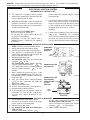
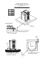
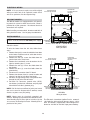
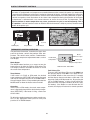
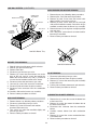
The heater requires water flow and positive pressure to fire and operate properly. It must therefore be installed
downstream of the discharge side of the filter pump. A typical installation is plumbed as follows:
1. The inlet side of the filter is plumbed directly to the discharge side of the filter pump;
2. The outlet side of the filter is then plumbed to the inlet of the heater; and
3. The outlet of the heater is plumbed to the return line to the pool or spa. The pump, filter and heater are thus
plumbed in series.
Plumbing from the heater back to the pool or spa must not have any valves or restriction that could prevent flow
when the pump is operating.
CHEMICAL
INSERTION POINT
(IF IN THE PIPING
SYSTEM)
VALVE CLOSED
WHEN SYSTEM
IS HEATING THE POOL
HEATER
WITH INTERNAL
BYPASS
VALVE CLOSED
WHEN SYSTEM
IS HEATING THE SPA
ISOLATION
VALVE
TO SPA
BALL VALVE
FILTER
PUMP
COARSE
STRAINER
PRESSURE
RELIEF VALVE
PUMP
UNION
CHECK VALVE
TO POOL
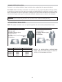
CAUTION: An additional source of heated water, e.g. a solar system, must be connected to the main line
ahead of the heater inlet pipe in order for it to act as the primary heat source. If the primary system provides
adequate heat to maintain set-point, the heater will not fire. Be advised that the control panel will then display
sensed water temperatures downstream of the primary heating system, rather than the temperature of the
water exiting the pool.
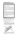
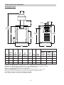
Heater must be located so that any water leaks will not damage the structure of adjacent area. PVC pipe may
be glued directly into header unions (Standard models only).
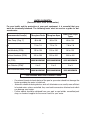
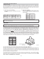
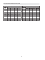
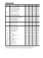
FLOW RATES
MODEL
PIPE SIZE
206/207
1-1/4”–1-1/2” - 2”
20
125
266/267
336/337
1-1/4”–1-1/2” - 2”
1-1/4”–1-1/2” - 2”
25
35
125
125
406/407
1-1/4”–1-1/2” - 2”
40
125
*When flow rates exceed maximum GPM an external auxiliary bypass valve is required. See external bypass valve
section for details.
MIN. GPM MAX. GPM*
Fig.# 2012
POLYMER HEADERS
CAST IRON HEADERS (ASME)
21