1
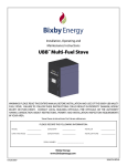
Installation, Operating and Maintenance
Instructions
MaxFireTM Multi-Fuel Room Heater
WARNING! Please read this entire manual before installation and use of the Bixby MaxFireTM Multi-Fuel
Room Heater. Failure to follow these instructions could result in property damage, bodily injury or even death.
Contact local building officials, fire officials or the authority having jurisdiction about restrictions, permits and
installation inspection requirements in your area.
Save these instructions for future reference.
PLEASE RECORD THE FOLLOWING INFORMATION:
MODEL
_______________
DEALERSHIP
DATE PURCHASED
_______________
DEALER PHONE _______________ INSTALLER PHONE
SERIAL NUMBER
_______________ INSTALLER
____________________________
Bixby Energy Systems
877-500-2800
www.bixbyenergy.com
_______________
_______________
TABLE OF CONTENTS
Safety Information
Minimum Clearances to Combustible Materials
2
Specifications
4
Planning the Installation
Performing the Installation
Optional Thermostat Operation
Leveling the Room Heater
6
Venting Installation and Instructions
Vent System Approvals
Venting Components
Inspections
Permits
Vent Maintenance
Vent Location
Location of Exhaust
General Vent Installation Instructions
9
Log Placement Instructions
20
Operating Instructions
21
Fuel
Start Up
Flashing Indicator Light System
Maintenance and Cleaning Procedures
Fire Pot/Burner
Ash Drawer
Heat Exchanger Tubes
Soot and Fly-ash Formation and Need for Removal
Cleaning the Exhaust Manifold
Exhaust Fan
Fuel Hopper
Cleaning the Glass
Cleaning the Feeder Tube
Cleaning the Lower Paddle
Cleaning the Air Filter for the Ignition Air Compressor
Replacing the Room Heater Filter
24
Troubleshooting Procedures
29
Wiring Diagram
31
Service Parts List
32
Optional Accessories
34
Venting Parts List
35
Maintenance Log
38
2020866 REV A
1
SAFETY INFORMATION
1.
Install and use only in accordance with these installation and operating instructions, page 9. Contact
local building officials, fire officials, or the authority having jurisdiction about restrictions, permits,
and inspection requirements in your area.
2.
Refer to instructions and local codes for precautions required for passing the vent pipe through a
combustible wall or ceiling. Inspect and clean vent system frequently in accordance with manufacture’s
instructions.
3.
DO NOT INSTALL A FLUE DAMPER IN THE EXHAUST VENTING SYSTEM OF THIS UNIT.
4.
DO NOT CONNECT THIS UNIT TO A CHIMNEY SERVING ANOTHER APPLIANCE.
5.
INSTALL VENT AT CLEARANCES SPECIFIED IN THE VENTING SECTION.
6.
For use with only whole corn kernels, wood pellet fuel or approved pelletized biomass.
7.
DO NOT BURN GARBAGE, OR FLAMMABLE FLUIDS SUCH AS GASOLINE, NAPTHA OR
ENGINE OIL IN YOUR BIXBY ROOM HEATER. Store any fuel away from your heater.
- Pellet stove starter gel may be used to assist in the lighting of the Room Heater. See lighting
instructions.
8.
Always unplug the heater before cleaning or servicing.
9.
Dispose of all ashes in a metal container.
10.
The use of a protective screen (i.e. fireplace screen) is recommended when children or animals are
present.
11.
DO NOT INSTALL IN A SLEEPING ROOM.
12.
The door must be closed and latched during operation. Always allow the Room Heater to cool before
opening the door to clean the firebox and / or the glass. If door must be opened during operation, use
caution as embers may escape from combustion chamber.
WARNING: Biomass (i.e. corn, wood) is a solid material and by its very nature will accumulate ash that
must be cleaned out of the Room Heater and venting on a regular basis. See cleaning and
maintenance schedule. FAILURE TO DO SO MAY VOID WARRANTY.
NOTE:
It is recommended that a carbon monoxide detector be installed to ensure protection from the
hazards of carbon monoxide. It is also recommended that a smoke detector be installed for
early warning in case of fire.
CAUTION: FRONT SURFACES OF THE BIXBY ROOM HEATER WILL BE HOT WHEN THE
UNIT IS IN OPERATION. DO NOT TOUCH, AND KEEP CHILDREN AND CLOTHING
AWAY. CONTACT MAY CAUSE SEVERE BURNS. KEEP FURNISHINGS AND OTHER
COMBUSTIBLE MATERIALS AT LEAST 2 FT. (610 MM) DISTANCE AWAY FROM THE
BIXBY ROOM HEATER.
2
2020866 REV A
MINIMUM CLEARANCES TO COMBUSTIBLE MATERIALS
C
B
B
B
B
B
A
Floor Protector
E
D
Free Standing and Alcove (rear only) Installation Clearances:
A
B
C
10.5” (267mm)
2”
(50mm)
12”
(305mm)
NOTE:
D
E
6”
3”
(150mm)
(75mm)
Minimum clearances are for temperature concerns and do not allow for enough room
for maintenance. Please allow enough room on the sides for routine maintenance,
6” - 12” (150mm - 305mm) of clearance to non-movable objects (i.e. walls)
is recommended. Also, clearance to the back of the Room Heater is needed for
replacement of the filter.
Use a non-combustible floor protector under the unit, extending 3” (76mm) past the side of unit
(or less if installed at closer clearances) and 6” (150mm) in front of Room Heater door.
Alcove Dimensions (Rear Vent Only):
Minimum Height - 42” (1065mm), Minimum Width - 32” (815mm),
Maximum Depth - 24” (610mm)
2020866 REV A
3
SPECIFICATIONS
Fuel:
Multi-fuel System: Dry shelled corn, Wood Pellets (recommended maximum size approximately ¼ in. diameter x 1¼ in.
long), or “BIXBY” certified Blue or Green Biomass pellets. The use of “cracked corn” is not recommended due to feed and
burn issues. The use of lower quality corn with foreign material (cobs, stones, or other material) may cause feed issues. In
addition, the use of seed corn is not recommended due to the coating interfering with the operation of the Room Heater. When
loading the corn into the hopper, remove as much foreign material as possible. See Operating Instructions (page 21) for more
information.
Level
Approx. Feed Rate
Time Between
Approximate Hours/
lbs/hr (kg/hr)
Ash Dumps *
Full Load *
1
1.8 (0.8)
21 hrs
57
2
2.1 (1.0)
17 1/2 hrs
48
3
4
5
6
7
8
2.3 (1.1)
2.6 (1.2)
3.0 (1.4)
3.5 (1.6)
3.9 (1.8)
4.6 (2.1)
16 hrs
14 hrs
12 1/2 hrs
10 1/2 hrs
9 1/2 hrs
8 hrs
43
38
34
29
26
22
*Assumes running at a single level, actual time will vary as the burn level changes,
starting and shutting down, and trim knob adjustments.
Heating Area:
Varies depending on floor plan, heat loss, geographic location, altitude, heater venting configuration, moisture
content of fuel and climate.
Installation:
Install in accordance with “BIXBY” instructions and local building codes.
Shipping Weight:
380 pounds (172 kg)
Electrical:
120 VAC, 60 Hz., 15 amp Service Required, dedicated line recommended
Start: 10 Amps
Run: 2 Amps
Dimensions:
Height = 33 in (838 mm)
Width = 28 in (711 mm)
Depth = 30 in (762 mm)
Fuel Hopper Capacity: 2.4 cu. ft. (approx. 106 lbs. shelled corn)
Listing:
The Bixby MaxFireTM Multi-Fuel Room Heater was tested by OMNI-Test Laboratories, Beaverton, Oregon
to ASTM E1509 and ULC C1482 (report number 223-S-06-2). Emission tests were also conducted per the
USA Environmental Protection test methods 28A and 5G for particulate emissions. The Max-FireTM is exempt
under 40 CFR 60.531, therefore the results have not been submitted to the EPA.
The results are as follows:
4
Category 1 (low burn)
Category 2 (medium low burn)
Category 3 (medium high burn)
Category 4 (high burn)
2.3 grams per hour (.081 ounces)
2.0 grams per hour (.070 ounces)
2.42 grams per hour (.085 ounces)
2.21 grams per hour (.077 ounces)
Overall weighted average
2.25 grams per hour (.079 ounces)
2020866 REV A
IMPORTANT:
Proper material handling equipment must be available to safely transport and position the Bixby Room Heater.
1.
Remove the protective packaging, using appropriate tools, and detach the unit from its
shipping pallet. The Room Heater is attached to the pallet with two bolts. Remove the side
pannels to gain access to the bolts.
2.
Using a suitable transporting device, move the unit to the desired location, centering it on
the Bixby Hearth Pad or an alternate protective plate. Care should be taken not to mar the
Hearth Pad. Placing protective material under the Bixby Room Heater when positioning
is recommended.
3.
Use the included bulls-eye level to level the unit by adjusting the height of its legs. Leveling the unit is required to maintain even fuel distribution. See Page 8 for more information.
MOBILE HOME INSTALLATION
WARNING: DO NOT INSTALL IN A SLEEPING ROOM.
CAUTION: THE STRUCTURAL INTEGRITY OF THE MOBILE HOME FLOOR, WALLS AND
CEILING / ROOF MUST BE MAINTAINED (i.e. Do not cut through floor joists, wall studs,
ceiling trusses, etc.)
1.
A Bixby Direct-Vent system must be used to provide an outside air inlet for combustion air
and must be unrestricted.
2.
The Room Heater must be secured to the mobile home by bolting it to the floor (using lag
bolts).
3.
The Room Heater must be grounded with #8 copper grounding wire or equivalent, terminated at each end with an NEC approved grounding device.
4.
Refer to pages 16 and 17 for typical horizontal or vertical mobile home venting installation.
5.
Refer to clearances to combustibles section on pages 3 and 11 for distances to combustibles
and appropriate chimney systems.
6.
Seal all wall and floor inlets to prevent air or moisture penetration. Check periodically to
ensure inlet is free of obstruction, such as snow and ice.
7.
Installation should be in accordance with the Manufactured Home and Safety Standard
(HUD), CFR 3280, Part 24.
2020866 REV A
5
PLANNING THE INSTALLATION
The Bixby Max-FireTM Room Heater is intended for use in buildings, manufactured homes or for mobile home
installation (see previous page for mobile home installation instructions).
CAUTION: The Max-FireTM Room Heater should not be installed at a location where it could come in contact
with curtains, drapes, walls, carpeting or other combustible surfaces. The Room Heater must not
be installed in a sleeping room. When choosing a location, proximity to an electrical outlet (do not
use an extension cord) and the best location for the venting outlet and its connecting piping should
be considered. See Venting Installation and Instructions, page 9.
CAUTION: This Room Heater must be installed only by an authorized dealer, and/or by individuals who are
technically qualified and versed in any local codes or regulations that may apply to installation and
application of heating equipment of this type. Clearances specified in this manual are minimum
and any reduction must be approved by the regulatory authority.
To assure safe operation, it is absolutely essential that a floor protective device of metal or other non-combustible
material be in place beneath the Room Heater. Note drawing below to determine dimensions the size of the mat.
Lightweight, properly sized hearth pads are available from Bixby Energy Systems in colors to match your Room
Heater.
A
A
B
The non-combustible floor protector should extend under unit 3
in. (76mm) to each side of unit when installed in a free standing
location and 6 in. (152 mm) in front of Room Heater door. The
floor protector can be less than 3 in.(76mm) if installed in an
alcove. See Minimum Clearances, page 3.
A = 3 in. (76mm)
B = 6 in. (152mm)
Figure 1
PERFORMING THE INSTALLATION
The unit is shipped completely assembled. It is enclosed in protective packaging material and attached to a
shipping pallet. A shop cart or other suitable material handling device (minimum capacity of 400 lbs. (180kg))
will be needed to transport the Bixby Room Heater to its desired location. To bring the Room Heater into the room
chosen, a door opening of at least 2 ft. 8 in.(80cm) will be needed. Appropriate tools will be needed to connect
the venting pipes and fittings, as well as a hole-cutting device for venting the piping to the outside. The side of
the shipping box can be used to help locate the Room Heater and the vent hole location.
6
2020866 REV A
OPTIONAL THERMOSTAT OPERATION
The Room Heater is designed so that it can be operated by a wall mounted thermostat. This option is not provided
directly from the factory, but can be purchased from your dealer or the Bixby website (www.bixbyenergy.com) or
any other “on/off” 24V AC wall mounted thermostat can be used. Do not use a powered thermostat to avoid
damage to the Room Heater. Follow the the thermostat installation instructions carefully.
NOTE:
Thermostat should be mounted on an inside wall and not in direct line with the Room Heater
convection air. A prefered location would be on an inside wall opposite the Room Heater.
When the thermostat is hooked up and calling for heat, the Room Heater will display the currently selected level
using the LEDs. If the thermostat is NOT calling for heat, the currently selected level will be displayed, but all
the LEDs will be slowly flashing in unison and the Room Heater run at level 1.
THERMOSTAT INSTALATION INSTRUCTIONS
2.
Remove the left side panel.
3.
Locate the Trim Pot / Thermostat bracket.
4.
Loosen the middle two screws on the thermostat
block and remove the metal jumper.
5.
Run the wire for the thermostat through the
black grommet on the back panel.
6.
Attach the wires of the thermostat to the two
terminals.
7.
Replace the side panel.
Thermostat connection
FEED
RATE
EXHAUST
FAN
-0+
-0+
3
3
5
3
��������
CORN
3
5
5
5
THERMOSTAT CONNECTION
Unplug the Room Heater.
FUEL
WOOD
2021781 REV A
1.
Figure 2
2020866 REV A
7
LEVELING THE ROOM HEATER
CAUTION:
THE ROOM HEATER SHOULD BE LEVELED BEFORE ATTACHING THE VENT PIPE.
The supplied bulls eye level can be used to level the Room Heater front-to-back and side-to-side, a 6 in.
level may also be used.
1.
Place the level centered side-to-side and about 4 in. (10cm) back from the front of the Room Heater on the
top surface. The bubble should end up centered inside the middle circle on the level. If the bubble is not
in that position, the bubble will be towards the high side of the Room Heater. See Figure 3.
2.
Locate the leveling feet on the bottom of the Room Heater. See Figure 4.
3.
Lift the Room Heater near the foot to be raised (low side, opposite the bubble on the level). A pry bar can
be used to lift the Room Heater with a wooden shim or something similar to protect the hearth pad.
4.
With the corner of the Room Heater elevated, place a piece of wood (or other blocking) under the Room
Heater to hold it while adjusting the leg. The leg length should be adjusted by hand, but if needed a wrench
maybe used. This will not work if the foot is turned all the way in, as that portion will not be accessible.
5.
Remove the block using the prybar and check adjustment.
6.
Proceed to adjust the feet until the bubble is centered inside the inner circle. This is a very important step
as the feed system is gravity fed and it will ensure that the fuel is fed into the burn pot correctly.
Bulls Eye Level
4”
Leveling
Legs
Figure 3
8
Figure 4
2020866 REV A
VENTING INSTALLATION AND INSTRUCTIONS
WARNING:
A MAJOR CAUSE OF VENT RELATED FIRES IS FAILURE TO MAINTAIN REQUIRED
CLEARANCES (AIR SPACES) TO COMBUSTIBLE MATERIALS. IT IS OF THE
UTMOST IMPORTANCE THAT THIS VENT SYSTEM BE INSTALLED ONLY IN
ACCORDANCE WITH THESE INSTRUCTIONS.
VENT SYSTEM APPROVALS
BIXBY DIRECT VENT PIPE is listed by OMNI-Test Laboratories, Inc. as a vent for BIXBY pellet and corn Room
Heaters only. NO OTHER PIPE IS LISTED FOR USE WITH BIXBY ROOM HEATERS. The use of non-Bixby
vent pipe will void the Room Heater’s warranty. The minimum clearance from this vent to combustible materials
is 2 in. (50mm). Combustible materials include but are not limited to lumber, plywood, sheetrock, plaster and lath,
furniture, curtains, electrical wiring, and building insulation of any kind. Never fill any required clearance space
with insulation or any other materials.
This vent is tested and listed by OMNI-Test Laboratories, Inc. to UL Standard 641 and to ULC/ORD-C441
(Canada) for safe low temperature venting systems, Type L, and produced under the factory inspection and followup program of OMNI-Test Laboratories, Inc.
NEVER INSTALL SINGLE-WALL PIPE TO THE Room Heater.
NOTE:
Proper planning for your vent installation will result in greater safety, efficiency, and convenience, saving both
time and money. Use only authorized BIXBY ENERGY SYSTEMS, INC. listed parts. Do not install damaged
parts.
TOOLS AND EQUIPMENT
Level (a six inch level is recommended)
Eye protection
Hammer
Screwdriver
Tape measure
High temperature waterproof sealant (min 500F)
Saber or keyhole saw
Stud finder
Adjustable wrench
Gloves
CAUTION: The Room Heater should be leveled before attaching the vent pipe. See page 8 for leveling
information.
2020866 REV A
9
VENTING COMPONENTS
48 in. (122 cm)
Vertical Vent Cap
36 in. (91 cm)
24 in. (61 cm)
Vent Pipe
12 in. (30 cm)
6 in. (15 cm)
Storm Collar
Decorative
Collar
Roof Flashing
Ceiling firestop support
Ceiling Firestop
Elbow
Thimble
Horizontal venting kit
Starter Collar
45 deg
9.5 in
(24 cm)
8 in.
(20 cm)
7.4 in
(19 cm)
5.5 in
(14 cm)
7 in.
(18 cm)
10.2 in
(26 cm)
Figure 5
Figure 6
INSPECTIONS
The use of pelletized fuel does not eliminate the need for inspection and cleaning. During the heating season,
inspect monthly.
PERMITS
Contact your local building officials, fire officials, or the authority having jurisdiction about restrictions, permits,
and inspection requirements in your area.
VENT MAINTENANCE
•
It is essential to have your venting and vent cap cleaned every year (each Spring) to remove soot
build up. If you have doubts about your ability to clean it, contact a professional chimney sweep. Use a
plastic, wood, or flexible steel brush. Do not use a stiff brush that will scratch the stainless steel liner of
your system.
•
Bixby Direct Vent systems must be installed so that access is provided for inspection and cleaning.
•
The vent system should be inspected at least once every month during the heating season.
•
Chemical cleaners must be used with great caution. Use only those which are absolutely guaranteed not to
corrode or have any other harmful effects.
•
In case of fire, shut off appliance and call your Fire Department. Do not use the appliance or vent until it
has been inspected for possible damage.
•
Due to the nature of solid fuels and their production of ash, Bixby Energy Systems is not responsible for
flue by-products that might discolor roofs or walls.
10
2020866 REV A
VENT LOCATION
When exiting through walls, make sure NFPA rules are followed for distance from windows and openings.
NOTE:
The termination cap will be HOT during operation. Consider it’s proximity to doors or other traffic areas.
W
G
10ft
3 ft.
2 ft.
3 ft.
2 ft
I
Note:
3 ft.
12 in
12 in.
4 ft.
7 ft.
Areas in red are not acceptable
locations for venting the room heater.
See below for more details
D
4 ft.
P
Figure 7
Follow the below listed NFPA rule for distance of exit terminal from windows and openings:
Per NFPA 211 10.4.1 all vents shall terminate above the roof surface (vertical venting). However, per NFPA 211 10.4.5,
Mechanical draft systems shall not be required to comply with 10.4.1 provided they comply with the following:
To ensure compliance with NFPA 211, the vent, shall be located in accordance with the following:
·
Not less than 3 ft. (.91m) above any forced air inlet (I) located within 10 ft. (3m).
·
Not less than 2 ft. (.61m) above grade, non combustible material ground cover is
recommended below the vent if less than 3 ft. (.91m) above grade.
·
Not less than 4 ft. (1.2m) below, 4 ft. (1.2m) horizontally from or 1 ft. (.3m) above any
door (D), window (W) or gravity air inlet into any building.
·
Not less than 2 ft. (.61m) from an adjacent building and not less than 7 ft. (2.1m) above
grade when located adjacent to public walkways / paths (P).
·
Not within 6 ft. (1.8m) of a gas service regulator vent outlet (G).
·
Not above a gas meter/regulator within 35 in. (.9m) horizontally of the vertical center line
of the regulator (G).
·
Not less than 3 ft. (.91m) below overhang (i.e. roof)
2020866 REV A
11
VENT LOCATION (CONT.)
Where passage through a wall, or partition of combustible construction is desired, the installation shall conform
to CAN/CSA-B365. See specific venting instructions (page 9) for more information.
The vent MUST NOT connect to any air distribution duct or system, or exhaust into an enclosed or semi-enclosed
area, but directly to the outside. Termination in a garage, attic, crawl space or other location in which fumes can
accumulate must be avoided. The installation with the vent extending vertically through the roof of the building
must have the proper termination cap installed. See specific venting instructions for more information.
Bixby recommends not installing a venting system in a pipe chase or permanent wall structure. Vent pipe should
be accessible for annual inspection and maintenance. Because solid fuel produces ash, Bixby Energy Systems
is not responsible for flue by-products that might damage or discolor building structures (walls, floors, roofs,
etc.). If the vent is to be installed inside an existing masonry chimney or other unheated structure (or if excessive
condensate forms), it is recommended that the pipe be insulated with non-combustible insulation (such as calcium
silicate). See your local dealer for insulation options.
LOCATION OF EXHAUST
The exhaust is located on the back of the stove. See Figure 8 for
dimensions.
NOTE:
NOTE:
If a hearth pad is used, add the height of the hearth
pad to the hight of the exhuast hole location from
the base, or measure from the top of the hearth pad
with the pad in place.
The shipping box can be used as a template for
locating the center of the hole for the vent pipe
in a horizontal venting configuration. Place the
diagram of the top of the stove on the hearth pad
and bend up the back side of the box.
5 7/8”
150mm
5.87
9.68
9 1/2” to 9 3/4”
240mm to 250mm
Figure 8
12
2020866 REV A
VENTING CONFIGURATIONS
The allowable venting configuration is to be 25 equivalent horizontal feet (7.5 m) or less as determined through
the following table:
Type of Pipe
90 deg elbow
45 deg elbow
Horizontal Pipe
Vertical Pipe
Altitude (in thousands of feet)
Qty
x
x
x
x
x
Factor (ft)
5 (1.5m)
3 (0.9m)
2 (0.6m)
0.5 (0.15m)
2.5 (0.8m)
Total
Total
Example:
NOTE:
Type of Pipe
90 deg elbow
45 deg elbow
Horizontal Pipe
Vertical Pipe
Altitude (in thousands of feet)
Qty
1
1
20
2
x
x
x
x
x
Factor (ft)
5
3
2
0.5
2.5
Total
5
Total
22
2
10
5
Horizontal runs, should be minimized (48 in. (1.2m) maximum per section) to prevent the
accumulation of ash. If possible replace horizontal offsets (two 90 degree elbows) with 45 degree
offsets (two 45 deg elbows) to go around building structures.
2020866 REV A
13
GENERAL VENT INSTALLATION INSTRUCTIONS
Follow the Room Heater manufacturer’s instructions and safety manual for maximum efficiency and safety.
Connect only BIXBY ENERGY SYSTEMS DIRECT VENT to BIXBY ROOM HEATERS.
CAUTION:
Connect only one flue per appliance.
Do not install a flue damper in the exhaust venting system of this unit.
Do not connect this unit to a chimney flue serving another appliance.
Over firing (too much fuel) can damage the Room Heater, vent pipe, or surrounding structures.
-
The use of three (3) sheet metal screws (self-tapping screws are recommended) is required at every connection. Do not use
longer than 3/4 in. (20mm) screws to prevent damage to the inner pipe. The indents in the pipe will assist in the placement of
the screws.
-
High temperature (500F/260C) silicone sealant is required on all 3 in. diameter inside joints. Either high temperature or
clear silicone sealant is recommended for the outer 5 in. outside joint. A 1/8 in. (3mm) bead, 1/2 in. (12mm) from the male
(cripped) end of both sections of pipe is recomended. See Figure 9.
-
The joint is not sealed unless the seam between the two outer sections of pipe is tight and the indent locks into the groove.
See Figure 10.
Inside bead
Outside bead
Indent locks into groove
Tight seam
Figure 9
WARNING:
14
Figure 10
ALWAYS MAINTAIN AT LEAST 2 in. (61mm) CLEARANCE FROM COMBUSTIBLE MATERIALS.
Where the chimney passes through additional floors and ceilings, always install a Firestop/Support.
2020866 REV A
VERTICAL INTERIOR INSTALLATION
NOTE:
NOTE:
Vertical exterior installation is not recommended due to excessive
condensation.
Bixby recommends not installing a venting system in a pipe chase or
permanent wall structure (other than to exit the room using the Wall
Thimble). Vent pipe should be accessible for annual inspection and
maintenance. Bixby is not responsible for damages to pipe chases,
or other wall structure resulting from vent failures.
The flue exit is on the back of the Room Heater and if vertical interior installation
is desired:
1.
Place the Room Heater according to the installation instructions. See Figure
7 for vent locations.
2.
Connect a Starter Collar to the back of the Room Heater using three screws.
See Figure 11.
3.
Insert an Elbow through the Stater Collar, into the back of the Room Heater.
Align and push together until snapped into locked position. See Figure 11.
4.
The outer pipe sections should not have a visable gap.
5.
Drop a plumb bob to the center of the Elbow connected to the Room Heater
flue outlet and mark center point on the ceiling, cut and frame a 10 in. x
10 in. (25cm x 25cm) square hole in the ceiling for the Ceiling Support
Firestop. See Figure 12.
6.
Connect the vertical pipe to the elbow attached to the Room Heater: Attach
each section of pipe by pushing male and female ends of pipe together until
pipe is in locked position. See General Vent Installation Instructions, page
14.
Install Wall Straps every four (4) feet in both vertical and horizontal vent
runs (required). See Figure 13.
8.
When the pipe passes through the Firestop/Support at ceiling, attach the
vertical pipe support around pipe and let it rest on the topside of the Firestop/
Support. If desired, a Decorative Collar can be installed over the Firestop/
Support for a finished look.
10.
After lining up for hole in roof, use same method as above and cut either a
round or square hole in the roof. Always cut the hole at least 4 in. (10cm)
larger than the diameter of the pipe. Install the upper edge and sides of
Flashing under the roofing materials and nail to the roof along the upper
edge. Do not nail the lower edge. The Vent Cap must extend a minimum
of 36 in. (91cm) above the roof. Also, the Vent Cap must be 24 in. (64cm)
higher than the highest part of the roof or structure that is within 10 ft. (3m)
of the chimney, measured horizontally. See Figure 13.
Seal all nail heads with high-temperature waterproof sealant. To finish,
apply high-temperature waterproof sealant where the Storm Collar will
meet the vent and Roof Flashing; slide Storm Collar down until it sets on
the Roof Flashing, tighten the bolt on the Storm Collar, put the Vent Cap on
and push to lock. See Figure 14.
2020866 REV A
Figure 11
Thimble
10 in (25cm)
See Figure 10.
7.
9.
Starter Collar
10 in (25cm)
Figure 12
10 ft (3m)
24 in (61 cm)
min
36 in (91cm) min.
Wall Straps
Figure 13
Vent Cap
Roof Flashing
Pipe
Storm Collar
Figure 14
15
HORIZONTAL THROUGH-THE-WALL-INSTALLATION
The flue exit is on back of the Room Heater, and if a horizontal through-thewall installation is desired:
1.
Place the Room Heater according to installation instructions. See
Figure 7 for vent locations.
2.
Locate vent termination per the NFPA rules. See Figure 7 (page 11).
3.
Cut and frame a 10 in. X 10 in. (25cm x 25cm) square opening in the
wall (the hole in the wall board may need to be larger). See Figure
12 (page 15). The telescoping Wall Thimble is to be installed in
the interior and exterior portion of the wall. (Wall Thimble adjusts
from 4 ¼ in. to 7 in. (11cm to 18cm) to accommodate most wall
thicknesses). See Figure 16.
Thimble
Decorative Collar
Figure 15
- The Wall Thimble flanges are to be attached to the supports with
four screws, one in each corner. Use of 1/2 inch or longer screws are
recomended.
Attach the outside vent flashing to the exterior wall with four screws.
Seal the outside section of the Horizontal Flashing and Wall Thimble
to the exterior wall with non-hardening sealant. Top tab is to be
placed under wall siding.
5.
Connect the Starter Collar to back of Room Heater and attach sufficient
pipe to the Room Heater to extend 4 in. - 8 in. (10-20cm) beyond the
Flashing. See Figure 16.
6.
7.
Anchor the pipe to the Horizontal Flashing with the three
brackets using the self tapping sheet metal screws shipped
with the flashing. The back/base of the cap is to extend
6 - 12 inches (15-30 cm) from the flashing. See Figures 15 and 17.
Wall Thimble - Outside
2 inch air gap around pipe.
Do not fill with insulation!
Figure 16
Flashing
Clips
Decorative
Collar
Attach the Vent Cap, note orientation of embossment, to the extended
pipe. Use high temperature (500 F/260 C) silicone sealant between
all pipe joints. See Figure 17.
NOTE: Some amount of soot and discoloration may occur on the outside of
the house.
NOTE: If ice forms on the Vent Cap in cold weather, run the Room Heater on
high for a couple of hours to clear.
16
Vent Cap
Flashing
Wall
- The Wall Thimble may be covered on the inside by the Decorative
Collar, see venting parts list for color options. It is important to slide
the collar on before adding additional venting.
4.
6”-12”
15-30cm
Starter
Collar
Figure 17
2020866 REV A
INSTALLATION IN A CATHEDRAL CEILING
1.
Mark a line on the side of the Cathedral Ceiling Support
Box to correspond to the line of the roof pitch. Allow for
the Support Box to protrude below the finished ceiling a
minimum of 2 in (5 cm). See Figure 18.
2.
Position the appliance at its proper location on the floor.
Pay close attention to the installation instructions as to
distances from combustibles, etc. The appliance must also
be positioned so the Support Box will not interfere with roof
rafters or other structural framing.
3.
Run a plumb line from the center of the flue exit on the
Room Heater to the ceiling. Mark the point on the ceiling
where the plumb line intersects. This represents the center of
the support box. Drill a small hole through the ceiling at this
point, so it can be located from the top of the roof.
4.
From the roof, locate and mark the outline of the Support
Box.
5.
Remove shingles or other roof covering as necessary to cut
the rectangular hole for the Support Box. Cut the hole 1/8 in
(3 mm) larger than the dimensions of the Support Box. The
rectangular hole should be centered on the small hole which
you drilled through the ceiling to mark the location. Again,
insure that you are not cutting through rafters or framing
members.
6.
Run the Support Box through the roof, and place it so that
the bottom of the Support Box protrudes at least 2 in (5 cm)
below the finished ceiling. Align the Support Box vertically
and horizontally with a level. Temporarily tack the Support
Box in place through the inside walls and into the roof
sheathing. See Figure 19.
7.
Figure 18
Figure 19
Using tin snips, cut the Support Box from the top corners
down to the roof line, and fold the resulting flap over the
roof sheathing. Before nailing it to the roof, run a bead of
non-hardening sealant around the outside top edges of the
Support Box so as to make a seal between the box and the
roof. Clean out any combustible material or debris from
inside the Support Box. See Figure 20.
Figure 20
2020866 REV A
17
INSTALLATION IN A CATHEDRAL CEILING (CONT.)
8.
Place the Vertical Support Clamp (5000576), around the top
of the hole in the bottom of the Support Box. See Figure
21.
9.
Connect the necessary amount of pipe sections to reach the
Room Heater at a point where the Vent Cap will extend a
minimum of 36 in (91 cm) above the roof. Also, the cap
must be 24 in (61 cm) higher than the highest part of the
roof or structure that is within 10 ft (3 m) of the chimney,
measured horizontally. See Figure 22.
10.
11.
12.
13.
18
Run the assembled pieces of vent pipe down through the
Clamp of the Support Box and connect to the appliance with
an Elbow and Starter Collar. See General Vent Installation
Instructions for details on connecting the pipe together.
Using a level, make slight adjustments in the position of the
appliance until the pipe is truly vertical. Tighten the bolts in
the Clamp.
Slip the Flashing over the pipe section(s) protruding through
the roof. Secure the base to the roof with roofing nails.
Insure that the roofing material overlaps the top edge of the
Flashing. See Figure 22.
Seal all nail heads with high-temperature waterproof sealant.
To finish, apply high-temperature waterproof sealant where
the Storm Collar will meet the Vent and Flashing; slide
Storm Collar down until it sets on the Flashing, put the Vent
Cap on and push to lock. See Figure 14 (page 16).
Clamp
Figure 21
Vent Cap
10 ft (3m)
24 in
(61mm)
36 in
(91mm)
Storm
Collar
Cathedral Ceiling
Support Box
Roof Flashing
Vent Pipe
Figure 22
2020866 REV A
CONNECTING TO EXISTING CLASS A CHIMNEY EITHER 6” OR 8”
Due to cleaning, inspection and condensation issues, Bixby no longer recomends connecting the Room Heater to
an existing Class A chimney.
INSTALLATION THROUGH THE SIDE OF A MASONRY CHIMNEY
Due to cleaning, inspection and condensation issues, Bixby no longer recomends connecting the Room Heater
to an existing masonry chimney. The venting may pass though the chimney to the outside, see previous page for
horizontal venting information.
2020866 REV A
19
LOG PLACEMENT INSTRUCTIONS
The use of the logs provided with the Room Heater is
optional.
1.
Locate the log box and remove the three logs. See
Figure 23.
2.
Place one of the “Y” logs on the right side of the burn
pot with the small end pointing towards the back of the
firebox. See Figure 24.
3.
Place the second “Y” log parallel to the front of the
Room Heater with the small end inside the first “Y”
log. See Figure 25.
4.
Place the straight log on the left side of the burn pot
with the end inside the “Y” of the second log. See
Figure 26.
Figure 23
Figure 24
Figure 25
Figure 26
20
2020866 REV A
OPERATING INSTRUCTIONS
FUEL
It is strongly recommended that only Dry Shelled Corn (whole kernels), Wood Pellets (recommended maximum size
approximately ¼ in (6mm) diameter x 1 ¼ in (32mm) long), Bixby Certified Corn or approved pelletized biomass fuel
be used in this Room Heater (Up to 8,700 BTU’s per pound). When using Dry Shelled Corn, clean corn (free of foreign
material like cobs, twigs, stones, etc.) with moisture level around 14% or less is recommended. The use of “cracked corn”
or seed corn is not recommended due to combustion and feed issues. Use Premium Wood Pellets made for use in Pellet
Room Heaters. High-grade wood pellets may be used, but cleaning of Bixby Room Heater and venting components may be
required more frequently due to excess ash resulting from fuel contamination from pitch and other impurities in the wood.
Caution should be used in burning unclean or high moisture corn. Corn that is unclean can produce undesirable deposits
and excessive ash in your Room Heater and heating efficiency can be dramatically affected. Corn of more than 14% could
generate mold in the hopper plus increase issues of condensation in the vent system. Use of unsuitable fuel may harm the
Bixby Room Heater and could void its warranty. High performance equipment, like your Room Heater, performs better
when given the best fuel.
The Room Heater is setup to burn corn from the factory. To burn wood pellets, simply open the left side pannel and locate
the fuel switch. Toggle the switch from “CORN” to “WOOD”. See Figure 27.
CAUTION: DO NOT BURN GARBAGE, OR FLAMMABLE FLUIDS SUCH AS GASOLINE, NAPTHA OR ENGINE OIL
FEED
RATE
EXHAUST
FAN
-0+
-0+
3
3
5
3
FUEL
WOOD
2021781 REV A
��������
CORN
3
5
5
5
THERMOSTAT CONNECTION
IN YOUR BIXBY ROOM HEATER. Store any fuel away from your heater.
Fuel Switch
Figure 27
2020866 REV A
21
START UP
NOTE:
NOTE:
CAUTION:
It is recommended that all gold or silver plated surfaces of the Bixby Room Heater be cleaned with a mild glass cleaner
before initial startup.
Use of a surge protector is recommended but not required for heater operation.
Operate the Bixby Room Heater only with the Fuel Hopper Door closed. Failure to do so may result in emission of
products of combustion from the Fuel Hopper under certain conditions. Do not overfill or extend this hopper.
1.
Open the Fuel Hopper Door on the top of the Bixby Room Heater and fill the hopper with Bixby Certified Corn or Biomass
Pellet Fuel, or an approved alternative. The capacity of the fuel hopper is approximately 106 lbs (48 kg).
2.
Verify that the fuel deflector is in place.
3.
Plug in the Bixby Room Heater’s grounded, 3-prong power cord. A grounded 115 volt, 60 Hz, 15 amp power supply is required.
Do not use extension cords. The furnished power cord must be plugged directly into a suitable outlet. Route power cord away
from the Bixby Room Heater. The exhaust fan will operate for approximatly 30 minutes when the heater is plugged in. This
is normal and is to ensure that any remaining combustion gases are removed in the event of a power outage.
4.
Manual Operation: Press the “On” button on the Control Panel. Then press the up/down arrows to bring heat output to the
desired level (the “Up” arrow increases the heat output, the “Down” arrow decreases it). The first time the Bixby Room heater
is used, or in cases when fuel in the hopper has been completely expended, sufficient fuel may not have been supplied to allow
the unit to start properly. If this happens, press the “Off” button, and then the “On” button to restart the unit after fuel begins
feeding into pot.
4a.
Optional Thermostat Operation: The thermostat will not start the Room Heater. When the thermostat is calling for heat, the
Room Heater will operatate at the selected level. When the thermostat is not calling for heat, the Room Heater will drop to level
1 to maintain the burn. The lights will blink when the thermostat is not calling for heat.
4b.
Manual Igniting Information: To manually iginite the Room Heater, press the “ON” button on the control panel. After the fuel
has started to be delivered to the burn pot, remove the ash drawer to access the bottom of the pot. Ignite the fuel by heating the
bottom of the burn pot with a MAP torch and maintain a flame. Once the fuel has ignited, replace and close the ash drawer and
verify the flame is stable. Wood pellets and starter gel may be used to assist the lighting. See below for cautions.
5.
Normally, the fuel will ignite within three to seven minutes, and full flame stability will be achieved within twenty minutes.
Heat production will then begin to reach the desired comfort level. If stable ignition does not take place within this time and
there is fuel building up in the burning area, press the “Off” button and then the “On” button to restart the unit.
6.
To shut down the Bixby Room Heater, press the “Off” button on the control panel, allow three to ten minutes for flame-out to
occur.
NOTE: The convection blower and the exhaust fan will continue to run for 30 minutes as the Room Heater cools.
7.
Power Outages: If there is a momentary (less than 10 second) loss of power, your heater will return to the set heating level. If
the power is interrupted for longer than 10 seconds, you will have to restart your unit after the power is restored. The #1 light
will be blinking, indicating a power failure.
NOTE:
Ash Drawer: Opening the ash drawer during heater operation will disable the dump process. Be sure to replace and
latch the ash drawer once emptied. If the ash drawer is open for more than 20 minutes, the unit will go directly into
shut-down mode.
NOTE:
Front Door: The door must be closed and latched while the Room Heater is running. Always allow the Room Heater
to cool before opening for cleaning. If the door is open for more than one (1) minute, the unit will go directly into
shut-down mode.
CAUTION:
Never use highly-volatile fuels such as gasoline, gasoline-type lantern fuel, kerosene, charcoal lighter fluid, or similar
substances in the Bixby Room Heater. Keep all such liquids well away from the Bixby Room Heater when it is in use.
Use of such fuels could cause over-firing and will void the unit’s warranty.
Wood pellets and starter gel may help if there is difficulty in manual starting, but do not use starter gel after startup.
22
2020866 REV A
FLASHING INDICATOR LIGHT SYSTEM
1
2
3
4
5
6
7
8
The 8 heat level indicator lights on the Bixby Room Heater are also designed to act as potential problem indicators.
Whenever one of these lights begins to flash, consult the chart below for reason and recommended solution.
Light #1
Power failure during Room Heater operation: Push the “Off” button and then the “On” button
to restart.
Light #2
Operating temperature not reached: Push the “Off” button and then the “On” button to restart.
Verify fuel level in the hopper.
Light #3
Exhaust system or hopper area is overheating. Reduce the feed rate (see Troubleshooting
section). If problem continues, contact your Bixby Dealer.
Light #2 & #3
Empty hopper or potential blocked flue warning. Check hopper for fuel. If fuel is present,
flue (exhaust) may be blocked. Clean the exhaust portion of the Room Heater and the attached
venting. See Maintenace and Cleaning Procedures for details. If problem continues, contact
your Bixby Dealer.
Light #4
Room Heater door is ajar (open). Make sure the door is tightly closed. If the door is open for
more than one minute, the Room Heater will shut down. Contact your Bixby Dealer if problem
continues.
Light #5
Ash Drawer is ajar (open): Make sure the ash drawer is tightly closed. The Room Heater will
not start if the ash drawer is not closed. If the ash drawer is open for more than 20 minutes, the
Room Heater will shut down. Close ash drawer and restart the Room Heater.
Light #6
Exhaust fan failure. Contact your Bixby Dealer for service.
Light #7
Fire pot mechanical malfunction: Push the “Off” button and then the “On” button to restart. If
malfunction continues, clear jam in burn pot once cool.
Light #7 & #1
Left igniter failed. Contact your Bixby Dealer for service. The Room Heater will continue to
operate, but will take longer to ignite from a cold start.
Light #7 & #2
Right igniter failed. See above. If both igniters have failed (Lights 7, 1 & 2), the Room Heater
will not be able to autostart. See Manual Lighting instructions (previous page).
Light #7 & #1-3 Internal error - possible ignitor electrical fault - unplug Room Heater and contact your Bixby
Dealer for service.
Light #8
2020866 REV A
Feeder wheel failure. Open hopper lid, remove feeder wheel cover, clear jam and restart Room
Heater. If this continues, contact your Bixby Dealer for service.
23
MAINTENANCE AND CLEANING PROCEDURES
The Bixby Room Heater has been designed to reduce the frequency of cleaning. However, if the simple maintenance
tasks detailed below are not performed - the Room Heater will not run properly and will lead to reduced heating efficiency,
increased operational problems and potential harm to its components. Reading and following the maintenance instructions
will keep the Room Heater running at optimal efficiency and will help to reduce problems over the long run. Many problems
can be solved by simply cleaning the Room Heater. This should be the first step in troubleshooting if the Room Heater is
not working properly.
NOTE:
Keep the area around the Room Heater clean and free of dust and debris.
CAUTION:
Always be sure to allow the Bixby Room Heater to cool and then unplug before any maintenance procedures are performed.
COMPONENTS REQUIRING PERIODIC CLEANING
FIRE POT/BURNER
This device is powered by an electric motor. The automatic
operation serves to clear the ash/deposits from the Fire Pot.
The sidewalls of the fire pot should be brushed monthly with the
included brush to remove deposits. If needed the pot may be
removed and soaked in a bucket of water. To remove the burner,
remove the fuel deflector, remove the top burner plate (handle in
front of the burner), remove the two clips holding the burner in
place and lift out the burner.
Fuel deflector
Fire pot
Good combustion is dependent on delivering the right amount
of air to the burn pot. Keeping the pot clean and the holes clear
will keep the air flowing to the fuel and reduce fuel related
problems.
ASH DRAWER
Figure 27
This container should be emptied as needed. With the Bixby
Room Heater simply undo the latches, pull the Ash Drawer out
and empty its contents.
CAUTION:
Drawer and contents may be hot.
NOTE:
Return drawer promptly (less than 20 minutes)
after emptying. While the drawer is open,
the Room Heater will not dump the ashes and
could postpone a cycle leading to build up in
the burner pot.
24
2020866 REV A
The ash drawer should be checked / emptied after burning
approximately 100-200 lbs. (1 - 2 full hoppers) of fuel. Actual
frequency will vary with usage, check every few days.
Ashes should be placed in a metal container with a tightfitting lid. The closed container of ashes should be placed on
a non-combustible floor or on the ground, well away from all
combustible materials, pending final disposal. If the ashes are
disposed of by burial in soil or otherwise locally dispersed, they
should be retained in the closed container until all cinders have
been thoroughly cooled.
Ash Drawer
Figure 28
HEAT EXCHANGER TUBES
Fly ash and other deposits will accumulate on the Heat Exchanger
Tubes over time and will act to insulate the tubes, reducing their
ability to heat the convection air and thus the home or building.
There are two banks of Heat Exchanger Tubes, both of which are
equipped with a cleaning lever. The levers are located above the
back ceramic pannels. To clean the tubes, pull the right side lever
straight up approximately 1’’ (2 cm). Carefully remove the back
panel. Repeat for the left side. Once the back panels have been
removed, slide the levers up and down untill they move freely.
Vaccum out the base of the Heat Exchanger Tubes and the
firebox. See Figure 29.
To replace the back panels, lift the left lever straight up slide the
left panel underneath. Repeat for the right hand side. See Figure
30.
Cleaning levers
Figure 29
SOOT AND FLY-ASH FORMATION AND NEED
FOR REMOVAL
Back Panel
The products of combustion will contain small particles of fly
ash. The fly ash will collect in the exhaust venting system and
restrict the flow of the flue gases. Incomplete combustion, such
as occurs during start-up, shutdown or incorrect operation of
the heater will lead to soot formation which will collect in the
exhaust venting system. Inspect the exhaust venting system at
least yearly, cleaning as required. Also, inspect any exhaust
outlet to maintain a clear and unobstructed exhaust/intake port.
CAUTION:
Use only an approved ash vacuum for this purpose.
Figure 30
2020866 REV A
25
EXHAUST FAN
CAUTION:
Unplug the Room Heater from its power
source before cleaning the impeller.
To access this component, open Right Side Panel, and remove
the fan cover. Using a brush and a vacuum, clean the impeller.
Inspect gasket. If it is torn, replace gasket before placing unit
in service.
Fan Cover
This cleaning should be performed once a year.
Figure 31
CLEANING THE EXHAUST MANIFOLD
The Exhaust Manifold should be cleared on a yearly
basis to ensure proper air flow in the Room Heater.
1. Turn off the Room Heater and allow to completely
cool (minimum of 2 hours).
2. Remove the back panels (see previous page for
instructions).
Clean this area
3. Move the cleaning levers up and down several times
until they move freely.
4. Using a shop vac, clean the ash around the base of
the tubes.
Figure 32
5. Use the Exhaust Manifold Cleaning Kit (available at
your dealer) to clean in behind the tubes.
6. Replace the heat exchanger cover plates.
26
2020866 REV A
FUEL HOPPER
The Fuel Hopper should be cleaned out on a regular basis
(monthly) to remove fines and ensure proper fuel delivery.
1.
Remove the hopper cover and set aside.
2.
Empty the hopper of as much fuel as possible by either
running the Room Heater, shop vac, or by hand.
3.
Vacuum the base of the feeder wheel to remove small
particles and other debris.
4.
Remove the feed wheel access plate and vacuum around
the feed wheel.
CLEANING THE GLASS
Feed wheel access plate
Clean this area
Figure 33
Depending on the fuel used and the amount of use, the glass
window will need to be cleaned. The glass can be cleaned using
any available glass cleaner. Do not use abrasive cleaners to clean
the glass. For tough cleaning use cleaners designed for ceramic
stove tops.
CAUTION:
Before cleaning the glass, allow the Room
Heater to cool (minimum 2 hrs). Do not spray
window cleaner on the glass if hot.
If the glass needs to be cleaned more than every 4 to 5 bags
of fuel (two full hoppers), contact your dealer to verify Room
Heater operation.
NOTE:
Feeder tube
Tighten door latch after the first month of
operation to maintain door seal.
CLEANING THE FEEDER TUBE
The Fuel Feeder Tube should be cleaned out on a regular basis
(monthly) to ensure proper fuel delivery.
1.
Allow Room Heater to cool, minimum 2 hrs.
2.
Open the Glass Door.
3.
Using a screw driver or small brush, scrape the inside of
the feeder tube.
Figure 34
If the tube needs to be cleaned more than every 4 to 5 bags of fuel
(two full hoppers), clean the fuel hopper (above).
2020866 REV A
27
CLEANING THE LOWER PADDLE
The Lower Paddle needs to be cleaned once a month in
order to operate efficiently. The ash dumping process
causes the holes in the lower paddle to eventually clog
with ash.
1.
Make sure the Room Heater is off and cool.
2.
On the control panel, push the “ON” and then
the “OFF” button immediately to clear the burn
pot and to place the lower paddle in the correct
position for cleaning.
3.
Unplug the Room Heater.
4.
Open the glass door or ash drawer to gain access to
the burn pot.
5.
Looking into the burn pot, insert a 1/8” drill bit,
toothpick, or similar diameter tool into the holes,
clearing each blocked hole.
Burn Pot
Holes
Figure 35
Air Compressor
CLEANING THE AIR FILTER FOR THE IGNITION
AIR COMPRESSOR
The air filter for the air compressor will only need to
be cleaned if the Room Heater is installed in a dusty
environment. Inspect filter annually. If it appears dirty,
remove and clean with a mild detergent and water. Once
dry, replace.
REPLACING THE ROOM HEATER FILTER
The air filter for the Room Heater is located on the back of
the Room Heater. The filter should be checked monthly
and replaced every 2 to 3 months depending on usage.
A clogged filter will reduce the efficiency of the Room
Heater. The filter can be replaced with most 16” x 16”
x 1” filters, or if not available, 20” x 16” x 1” filters. Do
not run the Room Heater with out the filter in place as
it’s primary function is to keep dust and dirt out of the
mechanical components in the Room Heater.
28
Figure 36
Air Filter
2020866 REV A
TROUBLESHOOTING PROCEDURES
When experiencing a malfunction, please read through the following list of possible problems to determine which
of them most closely approximates the trouble you are encountering. This will reduce troubleshooting time and
effort.
CAUTION: Always be sure to unplug electrical connection to Bixby Room Heater before any service procedures
are performed.
NOTE:
If you need to call the service department, verify the serial number (located on the left side of the
hopper) has been recorded on page 1 and have this manual with you.
NOTE:
Many performance issues can be solved through the use of the trim pot knobs located near the control
board behind the right side panel. Manual adjustment of either the fuel feed rate or the exhaust fan
speed may be necessary with different fuels (change in moisture for example), different seasons
(change in outside air temperature) or other changes in the operating conditions. Read through the
troubleshooting chart below to determine which knob to adjust and in which direction.
PROBLEM
POSSIBLE CAUSE/REMEDY
No response when Room Heater is Check the 120 volt power supply circuit for adequate voltage.
plugged in.
Check fuse on circuit board and replace if necessary.
No fire or fuel in burn pot.
Check to assure that there is fuel in the hopper.
Verify feeder wheel is turning. (See error codes)
Check to assure that the fuel feeder tube is not blocked by fines or “bridging” of fuel pellets
or kernels.
Push the “Off” button and then the “On” button to attempt a new startup.
Flame goes from high to low to high
Door or ash drawer is ajar (See error codes).
Feed rate is low, turn the feed rate up 1 notch using the Fuel trim pot knob and observe.
Repeat if necessary.
Smoke from convection air outlet Some wisps of smoke may occur during startup. This is normal.
(louvers) or hopper.
Check for debris under the feeder wheel.
Unburnt fuel in ash drawer
If the smoke doesn’t clear within 15 minutes or if excessive immediately shut down unit,
ventilate the area and contact your dealer.
A small amount is normal. During start up, the burner pot is emptied and as a result, unburnt
fuel left in the pot will be dumped.
Excessive ammounts is likely due to fire going out due to either too much fuel (smothering
the fire) or too much air (burning too fast). Observe Room Heater, if pot begins to fill with
fuel, turn fuel down. If fuel is burning too fast, turn air down.
Ash dump jamming on clinker
Hopper may have run out of fuel causing the fire to go out.
Burn may be too hot.
Feed rate / fan speed may need adjustment - turn fan speed down or feed rate up 1 notch and
observe. Repeat if necessary.
2020866 REV A
29
TROUBLESHOOTING CONT.
PROBLEM
Fire fails to start
POSSIBLE CAUSE/REMEDY
Be sure enough fuel is in the burn pot. Fuel should cover the bottom to a level of approximately
1/2’’.
Check bottom of burn pot for built-up ash or deposits and remove.
Check for flashing light #6, exhaust fan failure (contact your dealer).
Push the “Off” button on the control panel. Wait three minutes and push the “On” button
to attempt a new startup.
NOTE: When the Room Heater is cold (below normal room temperature), a “second start”
may be required. This is normal and a result of needing to pre-heat the burn pot.
Check the igniter fuses located on the control board. (See error codes).
Verify air pump is working during start up (feel pump for vibration).
Inspect Room Heater and venting to see if cleaning is needed.
Fire starts but shuts down after Check feeder chute to be sure fuel is feeding.
approximately 12 minutes.
Check to make sure exhaust thermocouple wire has not been disconnected from the control
(#2 indicator light)
board. (Two wire connection, upper right hand side).
If feeder stops after 12 minutes, electronics may be faulty; contact your dealer for service.
Dark yellow and or lazy flame, slow Check for spent fuel or too much fuel clogging bottom of burn pot.
start-up or excessive smoke present.
Burn pot, lower paddle holes may require cleaning.
Heat exchanger tubes may require cleaning.
Check vent pipe for blockage of exhaust gasses and incoming combustion air.
Feed rate / fan speed may need adjustment - turn fan speed up or feed rate down 1 notch and
observe. Repeat if necessary.
Excessive volume of fire, build-up of Burn pot may require cleaning
ash and dirty glass
The venting system or heat exchanger may need to be cleaned.
Burn pot filling with fuel
If the glass needs to be cleaned more than every 4 to 5 bags of fuel (two full hoppers),
contact your dealer to verify Room Heater operation.
Room Heater may not be level
Feed rate / fan speed may need adjustment - turn fan speed up or feed rate down 1 notch and
observe. Repeat if necessary.
Verify that the exhaust is not obstructed. See Maintenance and Cleaning instructions Cleaning Heat Exchanger Tubes. In addition, the vent pipe may need to be cleaned.
Holes in burn pot may need to be cleaned
Check the alignment of the burn pot components
Check the installation of the plates covering the heat exchanger tubes.
30
2020866 REV A
2020866 REV A
Fan
Convection
J12
J4
GREEN
BLACK
BLACK
J13
Connection for
External Thermostat
Air
Compressor
SPEED
SENSOR
Exhaust
Fan
BLACK
BROWN
BLUE
Fuse - 5x20mm 4 amp
GREEN/YELLOW
Figure 37
BLACK
J14
J6
RED
J8
TAN
ORANGE
J15
Trim POTs
Up
Burner
Motor
Feeder
Motor
J11
J10
J7
NC - Hopper Temperature
Safety Switch
J2
Bixby Circuit Board
Down
IGNITER
IGNITER
Fuse - 5X20mm 6.3A
Fuse - 5X20mm 6.3A
J18
Control Panel
J7
J5
J6
J4
J3
Exhaust Temperature
Thermocouple
Power Cord
Receptical
NO - Burner Limit Switch
NO - Door Switch
PURPLE
PINK
NO - Ash Drawer Switch
Fuel select
OPEN - FUEL A
CLOSED - FUEL B
YELLOW
BROWN
Off
On
31
TOLERANCES:
ANGULAR: 1 DEG
UNLESS OTHERWISE SPECIFIED:
DIMENSIONS ARE IN INCHES
WIRING DIAGRAM
QA APPR.
CHKD BY
DRAWN BY
SERVICE PARTS LIST
32
Item Number
Description
4000080
Igniter
4000121
Air pump
4000113
Burner drive motor assembly
4000006
Feeder wheel
4000098
Feeder wheel motor assembly
4000014
Convection fan capacitor
Part
Location
2020866 REV A
Item Number
Description
4000022
Heat exchanger cover plate - Right
Heat exchanger cover plate - Left
4000048
Air Filter
4000072
Control pad
4000064
Main control board
4000105
Exhaust fan
4000056
Exhaust fan gasket
2020866 REV A
Part
Location
33
Item Number
Description
4000353
Burner top plate
4000361
Feed wheel sensor
4000379
Fuel deflector
4000329
Thermocouple
4000337
Door Hinge
4000345
Door Latch
4000147
4000155
4000163
Door, Gold
Door, Nickel
Door, Black
Part
Location
OPTIONAL ACCESSORIES
Item Number
2013332
2012219
34
Description
Kit, Vacuum Cleaning Accessory
Thermostat, Remote
2020866 REV A
VENTING PARTS LIST
Description
Color / Size
Part #
Black
5001368
Wall Thimble
Aluminized Steel
5000526
Storm Collar
Stainless Steel/Galvanized
5000534
0/12 – 6/12
6/12 - 12/12
5000542
5000550
Stainless Steel
5001037
Wall Strap
Galvanized Steel
5000568
Vertical Support Clamp
Galvanized Steel
5000576
Firestop Support – Flat
Galvanized Steel
5000584
Vertical Termination Cap
Roof Flashing
Horizontal Flashing Kit
* Special order only
2020866 REV A
35
VENTING PARTS LIST (CONT.)
Description
6” Straight Pipe
12” Straight Pipe
24” Straight Pipe
36” Straight Pipe
48” Straight Pipe
45 Degree Elbow
90 Degree Elbow
Firestop Support Cathedral Ceiling
Trim Ring
Starter Collar
Color / Size
Part #
Black
5000055
Blushtone*
5000063
Hunter Green*
5000089
Black
5000170
Burgundy*
5000196
Hunter Green*
5000203
Black
5000237
Blushtone*
5000245
Hunter Green*
5000261
Black
5000295
Blushtone*
5000302
Hunter Green*
5000328
Black
5000352
Blushtone*
5000360
Hunter Green*
5000386
Black
5000419
Blushtone*
5000427
Hunter Green*
5000443
Black
5000477
Blushtone*
5000485
Hunter Green*
5000500
Black
5000592
Blushtone*
5000609
Hunter Green*
5000625
Black
5000641
Blushtone*
5000659
Hunter Green*
5000675
Black
5000691
* Special order only
36
2020866 REV A
VENTING PARTS LIST (CONT.)
Description
Decorative Collar
Sheet Metal Screw
2020866 REV A
Color / Size
Part #
Black
5000740
Blushtone*
5000758
Hunter Green*
5000774
Black
5000857
Blushtone
5000865
Hunter Green
5000881
37
MAINTENANCE LOG
Date
38
Service Performed
Notes
2020866 REV A