1
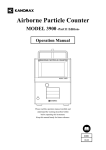
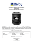
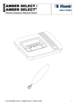
HANDHELD CPC
MODEL 3800
Operation Manual
Read this manual carefully and understand the
warnings described in this manual before operating the product.
Keep this manual handy for ready reference
Kanomax Japan Inc.
2-1 Shimizu, Suita-city,
Osaka 565-0805, Japan
TEL:+81-6-6877-0177
FAX:+81-6-6877-6849
01001
06.06
Thank you for purchasing a product of Kanomax Japan Inc.
Please read this operation manual carefully and operate the instrument
appropriately by following the instructions given in this manual.
List of Components
■ Standard
Items
Model
Quantity
3800
1
AC Adapter
3800-01
1
Zero Filter
3800-02
1
Condensation Particle Counter (CPC)
Alkaline Batteries (AA)
6
Alcohol Bottle
3800-03
1
Storage Cap
3800-04
1
Alcohol Cartridge
3800-05
1
Spare Felt and Wire Mesh
3800-06
2
PC Communication Cable
3800-07
1
Carrying Case
3800-08
1
Operation Manual
1
Measurement Software
1
■ Options
Items
Model
Quantity
Printer (100V)
3800-09
1
Printer (200V)
3800-10
1
Printer Communication Cable
3800-11
1
Charger
3800-12
2
Nickel Metal Hydride Batteries (AA)
3800-13
6
i
Important Safety Information
Types and definitions of warning signs used in this operation manual are shown below.
Danger:
To prevent serious injury or death
Items under this heading show measures to prevent serious injury or death,
which may result if the instructions in this manual are not followed and the
instrument is operated inappropriately.
Caution:
To prevent damage to the product.
Items under this heading show measures to prevent damage to the product and
conditions that affect our product warranty.
[Description of Symbols]
This symbol indicates a condition (including danger) that requires caution. The subject of
each caution is illustrated inside the triangle (e.g., high temperature caution symbol shown
on the left).
This symbol indicates prohibition. Do not take a prohibited action shown inside or near
this symbol (e.g., disassemble prohibiting symbol shown on the left).
This symbol indicates a mandatory action. A specific action is given near the symbol.
ii
Danger
This instrument is a Class 1 Laser Product.
A Class 3B laser diode is used as
a light source.
Laser Warning
Never disassemble the product.
Disassembly of the product
may present danger on human health.
CLASS 1 LASER PRODUCT
Laser Warning Label
○ Never disassemble, modify or repair.
Do not modify /
disassemble
-
This instrument uses a Class 3B laser diode as a light source. Disassembly is
very dangerous.
Disassembly may cause short circuit and/or other failure in performance.
○ Require proper handling/use in accordance with the instructions provided in
this operation manual.
-
Improper usage may cause electric shock, fire hazard, or damage.
Handle Properly
○ If abnormal noise, smell or smoke is observed, or if liquid has entered the
instrument, turn off the instrument immediately, remove the batteries or pull
out the plug
-
Negligence may cause electric shock, fire hazard or damage.
Please contact your distributor or KJI’s service center for repair.
○ Do not use or keep the instrument in an environment where ambient
temperature reaches 30 degrees C or above.
Prohibited
Installation
-
Use of the instrument out of the specified temperature range may cause
extreme deterioration in performance.
It may also deteriorate the insulations of the electrical components, which may
cause short circuit or fire hazard.
○ Pull out the plug when the instrument is not in use.
- Negligence may cause electrical shock, fire hazard, or circuit damage.
○ Before using the AC adapter, make sure that there is no dust accumulated on
the plug. The plug must be connected to a dedicated receptacle of 100-240V.
- Negligence may cause a fire hazard.
○ Use the AC adapter supplied with the instrument.
- Use of other commercially-available AC adapters may cause short circuit or
fire hazard, due to the possible difference in polarity and standards.
iii
Caution
○ If the instrument is not to be used for a long period, the batteries must be
removed from the battery compartment.
Do not leave spent batteries in the battery compartment as well.
正しく取扱う
Handle
Properly
-
Negligence may cause battery leakage.
○ Do not use or keep the instrument in a hot and humid environment or in an
environment with extremely low temperature/humidity.
Do not leave the instrument exposed to direct sunlight for long periods.
Prohibition
The instrument may not function properly outside the specified temperature
range.
(Temperature range 15-30 degrees C, RH below 85% without condensation)
○ Do not wipe the instrument with a volatile solvent.
Prohibition
The body may deform or deteriorate. Use soft dry cloth to remove stains. If
stains persist, soak the cloth in a neutral detergent and wipe the instrument
with a soft cloth.
Do not use volatile solvents such as thinner and benzine.
○ Do not apply strong shock or place/drop anything heavy on the instrument.
-
Negligence may cause damage or malfunction to the instrument.
Prohibition
○ Discharge built up static electricity from your body before touching the instrument.
-
The built up static electricity may influence the readings and cause damage to
the circuit.
iv
Contents
1. Description of Components ................................................................................... 1
1.1 Condensation Particle Counter (CPC)..................................................................1
1.2 Operation Panel ....................................................................................................2
2. Setup Before Measurement................................................................................... 5
2.1 Battery / AC Adapter Setup..................................................................................5
2.1.1 Battery Setup .....................................................................................................5
2.1.2 AC Adapter Setup ..............................................................................................6
2.2 Charging and Installing the Alcohol Felt.............................................................8
2.2.1 Checking Components........................................................................................8
2.2.2 Charging the Alcohol Cartridge.........................................................................9
2.2.3 Installing the Alcohol Cartridge ........................................................................9
3. How to Take Measurements ............................................................................... 10
3.1 Getting Started....................................................................................................11
3.1.1 Daily Zero Check ..............................................................................................11
3.1.2 Keypad ..............................................................................................................11
3.1.3 Tilting the Instrument .....................................................................................12
3.2 Measurement Modes ...........................................................................................13
3.2.1 Normal Mode ....................................................................................................14
3.2.2 Repeat Mode .....................................................................................................15
3.2.3 Programmed Mode <P. MODE> ......................................................................16
3.2.4 Count Mode ......................................................................................................17
3.3 Menu Setting .......................................................................................................18
3.3.1 Repeat Mode Setting ........................................................................................19
3.3.2 Viewing Program..............................................................................................20
3.3.3 Data Output......................................................................................................21
3.3.4 Utility................................................................................................................23
3.3.4.1 Adjusting Time and Date ..............................................................................24
3.3.4.2 Printer Setup .................................................................................................25
3.3.4.3 Deleting Data ................................................................................................25
3.3.4.4 Adjusting LCD Contrast ...............................................................................26
3.3.4.5 Alarm Setting ................................................................................................26
3.3.4.6 Beep Setting ..................................................................................................27
4. Maintenance ........................................................................................................ 28
4.1 Daily Zero Check .................................................................................................28
4.2 Alcohol Cartridge ................................................................................................28
4.3 Frequency of Maintenance..................................................................................30
5. Main Specifications ............................................................................................. 31
6. Troubleshooting................................................................................................... 32
7. Warranty and After Service ................................................................................ 34
8. Contact Information ............................................................................................ 35
1. Description of Components
1.1 Condensation Particle Counter (CPC)
Unit: mm
120
Inlet
Battery
Compartment
280
Keypad
Printer
Output Port
USB Port
AC Adapter
Jack
120
Power Switch
Alcohol Cartridge Insertion Opening
* The slight clacking sound heard when shaking the instrument is generated by the tilt
detection sensor equipped inside the instrument, and is normal.
1
1.2 Operation Panel
<Description of Display Screen>
1. Date & Time
1
Indicates year, month, day and time.
To set the date & time,
3
see 3.3.4.1 Adjusting Time and Date (page 24 ).
2. Remaining Battery Level
4
Indicates remaining battery level.
6
For details, see 2.1.1 Battery Setup (page 5).
3. Reading (Measured Value)
Indicates particle number concentration or
number or particles depending on the measurement mode.
The reading will be updated once each second.
For the description and details of the mode, see 3.2 Measurement Modes (page 13).
4. Absolute Pressure at Inlet
Indicates absolute pressure at the inlet.
5. Remaining Memory Level
Indicates remaining memory of the CPC in 8 levels.
Memory capacity: 10,000 pieces of data.
Black squares indicate unused memories, which will turn white when used.
6. Error Message & Status Display
Error messages and status will be indicated.
See list below for details.
7. Measurement Mode
Indicates the measurement mode which is currently selected.
The modes are: <Normal>, <REPEAT>, <P.MODE> and <COUNT>.
For the description and details of the mode, see 3.2 Measurement Modes (page 13).
2
2
5
7
List of Error Messages (In priority order)
List of Status Display
1.【LASER ERR】---Laser failure.
2.【PUMP ERR】--- Pump failure.
3.【TEMP ERR】--- Temperature control failure
4.【ALCOHOL ERR】--- Alcohol supply failure.
5.【FLOW ERR】--- Flow control failure.
6.【COUNT OVER】--- Count exceeding 100,000
1.【HOLD】
Screen is in “hold” for printing.
2.【PUMP STOP】
Pump is stopped on detecting a tilt condition.
3.【ALARM】
Set alarm level is exceeded under an alarm
activated condition.
4.【MEMORY OVER】
particles/cc, or in <Count> mode, when
exceeding 9,999,999.
7.【COM ERR】--- Communication error.
8.【PRINT ERR】--- Printer output failure.
No memory remaining for data storage.
5.【WAITING TIME】
When operating in <P.MODE>, the instrument
is in standby during an interval.
6.【WARMING UP…】
When operating in <P.MODE>, the instrument
is warming up to recover from standby (10
min.)
* In case of having multiple errors at the same time, one error message will be displayed on the
screen in the priority order as shown above.
On the printed data, the error status will be indicated by the error message number which
corresponds to the above. For details, see 3.3.3 Data Output (page 21).
e.g. When having the error statues 2 and 3, “S”=2 will be shown on the printed data.
If indicated as “S”=5, this means that there was a flow error.
* For measures to be taken to solve an error status, see Section 6. Troubleshooting (page 32).
3
<Description of Keypads and Indicators>
The CPC can be operated by using the keypad provided on the grip at the center of the CPC.
1. [UP] key
Used for operations such as; canceling warm-up, selecting/setting items, and changing values.
2. [LEFT] key
Used for operations such as; selecting the 【PRINT】 mode, returning to the previous screen, and
returning to the previous digit when setting values.
3. [RIGHT] key
Used for operations such as; selecting the 【PRINT】 mode, and
proceeding to the next digit when setting values.
4. [DOWN] key
Used for operations such as; selecting/setting items, and changing values.
5. [ENTER] key
Used for operations such as; entering a setting, and
starting the <P.MODE>.
6. LED
POWER---Green light is turned on while power is on.
PARTICLE---Red light blinks on detecting particles.
1
5
2
3
4
6
<Description of Components>
Name
Function
Inlet
Inlet for the sample air.
For cleaning the optical system, operatate the instrument with the filter
attached to the inlet.
Keypad
Used for performing various operations.
Power Switch
Turns ON/OFF the power.
The power will be turned ON/OFF by pressing the switch.
The switch cannot be operated during a measurement in each mode.
AC Adapter Jack
The supplied AC adapter (MODEL S-8458) must be used.
When the AC adapter is connected, even if the batteries are installed, the
power will be supplied from the AC adapter.
USB Port
Used when connecting the CPC with the PC to perform operations such as
data transfer and program writing. After the supplied software is installed
on the PC, connect the CPC and the PC with the supplied communication
cable.
* A printer cannot be connected to this port.
Printer Output Port
Used when outputting stored data from an optional printer.
Alcohol Cartridge
Insertion Opening
Before performing a measurement, insert the alcohol-filled cartridge into
this insertion opening. When the instrument is not used (or stored), the
opening must be covered with a storage cap to prevent dust or dirt from
getting into the optical system.
4
2. Setup Before Measurement
2.1 Battery / AC Adapter Setup
The CPC may be powered by batteries or an AC adapter.
Setup the batteries or the AC adapter whichever is appropriate for your use.
2.1.1 Battery Setup
1. Slide the battery compartment lid located at
the backside of the instrument in the direction
of the arrow, and remove the lid.
2. Install the batteries. (* Note the polarity of the batteries.)
Six (6) AA batteries are required. Use alkaline batteries or
Ni-MH(nickel metal hydride) batteries. All of the six batteries
must be of the same type. Using different types of batteries
may result in leakage, or damage to the instrument.
* The batteries cannot be charged by the AC adapter.
Applicable Battery Types:
3. Close the lid in the reverse
procedure of opening the lid.
5
-
Alkaline Battery (AA)
-
Ni-MH battery (AA)
2.1.2 AC Adapter Setup
Insert the DC plug of the AC adapter into the
DC-9V connector located at the right side of the
CPC. When the AC adapter is connected, even if
the batteries are installed, the power will be
supplied from the AC adapter. There is no
problem having the batteries installed in the
battery compartment, however, if the batteries are
not to be used for a long period, they must be
removed from the battery compartment to avoid
battery corrosion causing a contact failure.
<AC Adapter>
Model:
S-8458
Input:
AC100-240V
Output: DC9V 1.4A
Polarity:
Caution
The AC adapter supplied with the instrument (MODEL S-8458) must be used.
Use of other commercially-available AC adapters may cause short circuit or
fire hazard, due to the possible difference in polarity.
6
<Remaining Battery Level>
Remaining battery level is indicated
at the right top of the screen.
As the remaining battery level drops, the indication on the display will change as below.
Require battery
replacement
Caution
-
-
When the battery runs out, the display screen will go off. Though the stored data, and present data
under measurement will be stored*, the battery must be replaced immediately.
If the instrument is not to be used for a long period, the batteries must be removed from the battery
compartment. If the batteries are left in the compartment for a long period, they might cause
corrosion resulting in contact failure.
Use the supplied AC adapter when continuously using the instrument for an extended period.
* The CPC is equipped with a backup power for keeping the memory even when the power is turned off.
The life of this backup power is 4-5 years. For replacing the backup power, please contact your
distributor.
7
2.2 Charging and Installing the Alcohol Felt
Danger
Isopropyl Alcohol used for this instrument is hazardous material.
Do not ingest or allow alcohol to contact your eyes or skin. Refer to the Material
Safety Data Sheet (MSDS) for handling and storing the alcohol in the alcohol
container.
Caution Always recap the alcohol container immediately after use to prevent absorption of
moisture and evaporation.
The isopropyl alcohol required for properly operating the CPC is a very high purity “reagent
grade” alcohol. Please refrain from using isopropyl alcohol that is available from stores such as
pharmacies or drug stores. Purity of those would be low, which may damage the CPC.
Any problems caused by a use of alcohol other than the isopropyl alcohol specified below will not
be covered under warranty.
Please ensure to use the appropriate alcohol with strict adherence to the handling directions.
For the method of supplying the alcohol, see 2.2.2 Charging the Alcohol Cartridge (page 9).
Chemical name: 2-Propanol
Synonym:
Isopropyl alcohol
Chemical formula: (CH3)2CHOH
Formula weight: 60.10
Assay:
99.5% or above
2.2.1 Checking Components
On supplying alcohol to the CPC, confirm that the following components and accessories are
prepared.
Required items:
- Alcohol bottle
- Storage cap
- Alcohol cartridge
- Isopropyl alcohol (not supplied with the instrument)
The alcohol cartridge must be stored in the alcohol bottle when not used in the CPC.
The storage cap must be used to seal the alcohol bottle, or to cap the alcohol cartridge insertion
opening of the CPC when the instrument is not in use.
8
2.2.2 Charging the Alcohol Cartridge
Caution
Do not leave the alcohol cartridge insertion opening of the CPC open longer
that necessary to prevent contamination of the optical system to cause
operation failure.
1. Turn off the CPC power.
2. Open the alcohol bottle by twisting the storage cap (or the alcohol cartridge) counter-clockwise
for about 1/8 turn. Place the storage cap (or the alcohol cartridge) on a clean surface such that
the storage cap (or the alcohol cartridge) stands on its end.
3. Pour isopropyl alcohol in the bottle up to the marked level, with caution not to tip the bottle and
spill the alcohol.
4. Make sure that the alcohol cartridge is clean. Insert the alcohol cartridge into the alcohol bottle,
and twist for about 1/8 turn until it locks into place.
5. After the alcohol cartridge is set, wait several minutes for the felt inside the cartridge to absorb
the alcohol. To fully charge the alcohol cartridge, it will take approximately 20-30 minutes.
2.2.3 Installing the Alcohol Cartridge
1. Remove the alcohol cartridge from the alcohol bottle, and gently shake down excess alcohol.
You do not need to wait for the outside surface of the cartridge to dry.
2. Insert the alcohol cartridge into the cartridge insertion opening of the CPC.
Align the groove at the side of the alcohol cartridge with the tab at the insertion opening, and
twist the alcohol cartridge clockwise for about 1/8 turn.
The alcohol cartridge should slide in easily with little force. DO NOT FORCE IT IN.
Always recap the alcohol bottle immediately after use to prevent absorption of
moisture and evaporation. Alcohol that is contaminated must be disposed.
When the CPC is not used, the alcohol cartridge must be stored in the alcohol bottle.
The alcohol bottle is designed to be safe for transportation and storage of the alcohol.
The alcohol cartridge will be soaked in the alcohol. The storage cap must be applied
to the cartridge insertion opening of the CPC to prevent dust and dirt from getting in.
Caution
Do not transport or store the CPC with the cartridge inserted in the CPC. The alcohol
may seep out and get in the optical system, which may affect future measurements.
Do not leave the cartridge insertion opening of the CPC open longer than necessary.
Apply the storage cap to the insertion opening for transportation and storage.
Always keep the storage cap and alcohol cartridge clean.
If the side of the cartridge and/or the inside of the cap is unclean, dust and dirt may
get in the instrument when operated, which may impair correct measurement.
9
3. How to Take Measurements
Press the power switch located at the side of the CPC to turn on the CPC.
A screen indicating the CPC model and firmware version information will be displayed. Then it will
automatically switch to a warm-up screen (Screen-1). Warm-up takes about 600 seconds. The
warm-up time remaining will be counted down on the display.
Remaining
warm-up time
Indication of
warm up status
Screen-1 Warm-up Screen
Menu operation can be performed from this screen by pressing the [ENTER] key.
For descriptions of the Menu operation, see 3.3. Menu Setting (page 18).
Warm-up can be canceled by pressing the [UP] key.
When warm-up is completed or cancelled, the screen will switch to the <NORMAL> mode screen
(Screen-2).
For descriptions of the <NORMAL> mode, see 3.2.1 Normal Mode (page 14).
Caution
When warm-up is cancelled before its completion, remaining warm-up
time will be displayed on the <Normal> mode screen (Screen-2). While
this warm-up time is displayed, the measurement value will not be
accurate.
10
3.1 Getting Started
3.1.1 Daily Zero Check
Before starting to use the CPC, zero check must be performed to confirm that the instrument is
operating properly. This zero check must be performed at least once a day, or before use if not used
daily.
1. Turn on the instrument, and wait for it to warm-up (requires approximately 600 seconds).
2. Attach the supplied zero filter.
3. The particle number concentration will become zero in approximately 10 seconds. Leave the zero
filter attached to the instrument for approximately 30 seconds in order to confirm that the zero
reading is stable.
4. Remove the zero filter, and the instrument will be ready for operation.
Caution
If the reading of the instrument does not become zero, please refer to
6. Trouble Shooting (page 32).
3.1.2 Keypad
The keypad located on the grip of the CPC
allows various operations of the CPC.
The keypad consists of 5 keys, which are used for;
moving between menu items, selecting an item,
adjusting and entering a setting.
When a key is pressed, there will be a beep
sound confirming the function.
This beep sound can be turned ON/OFF.
For turning ON/OFF the beep sound,
see 3.3.4.6 Beep Setting (page 27).
[UP]
[LEFT]
[ENTER]
[RIGHT]
[DOWN]
When the power is turned ON, the green LED at the “POWER” will light, and on detecting
particles, the red LED at the “PARTICLE” will blink.
11
3.1.3 Tilting the Instrument
The CPC is operated by using isopropyl alcohol which is absorbed into an alcohol cartridge.
If the instrument is tilted during operation, the alcohol will gradually seep out of the alcohol
cartridge. If this alcohol gets into the optical chamber, it may cause false particle counts and/or
damage to the optical system. This will temporary disable measurement, and in the worst case, it
will permanently affect the readings.
To avoid such problems, the CPC is equipped to generate an alarm, and stop the pump when the
instrument is tilted. In this case, a message 【PUMP STOP】 will be displayed. The alarm will go
off until the instrument is retuned to a horizontal position.
The pump will resume operation in 5 seconds after the instrument is returned to a horizontal
position. Then in approximately 10 seconds, the instrument will be ready for measurement.
Caution
Do not tilt the instrument up in a vertical position when observing the
display. If the instrument is tilted, there will be a beep sound, and the pump
will stop.
It is recommended that the instrument is placed on a substantially leveled
and stable surface.
12
3.2 Measurement Modes
There are four (4) measurement modes as listed below.
1. <NORMAL> Mode --- For details see 3.2.1 Normal Mode (page 14).
After warm-up, the instrument will automatically transfer to this mode.
Particle number concentration (particles/cc) and absolute pressure (hPa) can be measured.
Measured data cannot be stored.
This mode also allows setting of the Menu and printing an instantaneous value.
2. <REPEAT> Mode --- For details see 3.2.2 Repeat Mode (page 15).
The measurement is performed in accordance with the measurement condition set by the CPC.
Particle number concentration (particles/cc) and absolute pressure (hPa) can be measured.
Measured data can be stored.
3. <P.MODE> --- For details see 3.2.3 Programmed Mode (page 16).
The measurement is performed in accordance with the measurement program .set by the PC,
and written in the CPC.
Particle number concentration (particles/cc) and absolute pressure (hPa) can be measured
automatically.
Measured data can be stored.
4. <COUNT> Mode --- For details see 3.2.4 Count Mode (page 17).
Counts up the number of particles measured during a random time interval.
The number of particles and absolute pressure (hPa) can be measured.
Measurement Start/Stop is manually operated.
Measurement data cannot be stored.
This mode is suitable for performing a measurement in an environment where the particle
number concentration is low.
13
3.2.1 Normal Mode
This is the initial measurement mode switched to after completion (or cancellation) of warm-up.
Remaining warm-up time
*Displayed only when
warm-up is cancelled.
Screen-2 <NORMAL> Mode
The readings (measured values) will be updated once each second.
In this mode, measured values cannot be stored.
Various operations can be selected from this screen by using the [LEFT], [RIGHT], [UP],
[DOWN], and [ENTER] keys.
[LEFT] / [RIGHT] Key
On pressing the [LEFT] or [RIGHT] key,
the reading (measured value)will be in “hold”,
and 【HOLD】【PRINT】 will be displayed
on the screen as shown in Screen-3.
The display will be in “hold” under this condition,
and the reading can be printed from
Screen-3 <PRINT> Mode
a printer (optional) by pressing the [ENTER] key.
For releasing hold and returning to the
<NORMAL> Mode (Screen-2), press the [LEFT] or [RIGHT] key again.
If a printer is not connected, or the baud rates of the printer and the CPC are not
consistent, there will be an error message 【PRINT ERR】 shown at the left bottom
Caution
of the screen. Please confirm the connection and communication requirements.
For the CPC baud rate setting method and communication requirements, see 3.3.4.2
Printer Setup (page 25).
[UP] / [DOWN] Key
Selecting various measurement modes.
[UP] key
(* The [DOWN] key can be used to move in the opposite direction.)
<MENU> → <COUNT> → <P.MODE> → <REPEAT> → <MENU> …
[ENTER] Key
Returning to MENU screen. For details, see 3.3 Menu Setting (page 18).
14
3.2.2 Repeat Mode
This is a mode for performing measurement in accordance with the measurement conditions set by
the CPC. The readings (measured values) will be updated once each second.
For how to set the measurement conditions, see 3.3.1 Repeat Mode Setting (page 19).
Switch between
【NOT REC】 and 【RECORD】
by pressing the [LEFT] or
[RIGHT] key.
Screen-4 <REPEAT> Mode
On pressing the [LEFT] or [RIGHT] key, data storage will be switched between enabled/disabled.
【NOT REC(disabled)】
【RECORD(enabled)】
This operation can also be performed during and after a measurement.
A measurement will start on pressing the [ENTER] key on Screen-4.
During a measurement, a screen as below (Screen-5) will be displayed.
Number of sampling times.
Maximum, minimum,
and average of the
measured values.
Sampling progress indicator.
(In 8 levels.)
Screen-5 Measurement in <REPEAT> Mode
After completing the measurement, the measured values can be stored by pressing the [ENTER]
key when 【 RECORD 】 is displayed on the screen. If the [ENTER] key is pressed when
【NOT REC】 is displayed, the measurement will be terminated without storing the measured
values, and the screen will return to Screen-4.
The stored data can be viewed from the CPC. For how to view the stored data, see 3.3.3 Data
Output (page 21). In addition, the stored data can be transferred to the PC by using the supplied
software. For how to transfer the data, see Section 7 “Data Transfer” of the Software Operation
Manual.
To cancel the measurement before completion, press the [ENTER] key twice, and the measurement
will be terminated. In this case, if 【RECORD】 is displayed on the screen, the measured values up
to that point will be stored, and if 【NOT REC】 is displayed, the measured values will not be
stored.
While performing a measurement, the power switch cannot be operated. To turn off the power, the
measurement must be terminated first.
15
3.2.3 Programmed Mode <P. MODE>
This is a mode for performing automatic measurement
in accordance with the measurement program(s)
written in from the PC.
Maximum 5 programs can be set.
Select <P.MODE>. Then, in order to activate the
programmed measurement, press and hold the
[ENTER] key for a few seconds, and 【START】 will be
indicated on the screen (Screen-6) .
When 【START】 is indicated, the CPC is ready for
Screen-6 <P.MODE>
programmed measurement.
Make sure that 【START】 is indicated. If not indicated, the programmed measurement will NOT
be performed.
If the time interval before the programmed start time is 15 minutes or more, the pump and Peltier
operation will stop, and the message 【WAITING TIME】 will be indicated on the screen.
In this mode, the pump and Peltier will start operation 10 minutes before the measurement start
time of the program(s) 1-5, and the message 【WARMING UP…】 will be displayed on the screen.
The measurement will start automatically at the exact start time.
If there is any overlap between the measurement times set by the program(s) 1-5, the program
with an earliest start will have a priority over the other overlapping program(s), and the other
overlapping program(s) with the later start time will become invalid.
For canceling (deactivating) this mode, press and hold the [ENTER] key for a few seconds, and the
automatic measurement will be cancelled. The 【START】 indication on the display will turn off.
To perform daily measurement at a programmed time, set the program date as 00/00/00.
The CPC must be powered up in order to perform the programmed measurement.
While performing a measurement, the power switch cannot be operated. To turn off the power, the
measurement must be terminated first.
For details of the items set by the programmed measurement, see 3.3.2 Viewing Program (page 20),
and Section 5 “CPC Settings” of the Software Operation Manual for how to set the programmed
measurement.
16
3.2.4 Count Mode
This is a mode for counting up the number of particles.
The readings (measured value) will be updated
once each second.
Measurement will start on pressing
the [ENTER] key, and the number of particles
per second will be accumulated.
On the display, elapsed time and the
accumulated number of particles will be indicated.
Screen-7 <COUNT> Mode
Elapsed time
By pressing the [ENTER] key, counting up of particles and elapsed time will stop, and the
measurement will be terminated.
When the [ENTER] key is pressed again, the display will return to the initial display of the
<COUNT> Mode.
The maximum count is 9, 999, 999. When this is exceeded, the message 【COUNT OVER】 will be
displayed on the screen.
In this mode, measured values cannot be stored.
While performing a measurement, the power switch cannot be operated. To turn off the power, the
measurement must be terminated first.
17
3.3 Menu Setting
The Menu allows measurement setting and review, stored data review, and utility setting.
By pressing the [ENTER] key in the
<NORMAL> Mode (Screen-2),
the display will change to the MENU (Screen-8).
Items of the Menu are:
1. NORMAL MODE
・・・ To return to the <NORMAL> mode (Screen-2).
2. REPEAT SETTING
・・・ To set a measurement in the <REPEAT> Mode.
Screen-8 MENU
3. PROGRAM REVIEW
・・・ To view a measurement setting of the <P.MODE>.
4. DATA OUTPUT
・・・ To view, print, and delete stored data.
5. UTILITIES
・・・ To set various configurations.
Select the item you desire to set or view by using the [UP]/[DOWN] key, and press the [ENTER]
key to enter, and a screen of the selected item will be displayed.
You can return to the <NORMAL> Mode (Screen-2) also by pressing the [LEFT] key.
18
3.3.1 Repeat Mode Setting
To setup a measurement in <REPEAT> Mode:
On the MENU screen (Screen-8),
select “2. REPEAT SETTING” and press
the [ENTER] key. The display will
switch to the “REPEAT SETTING” screen (Screen-9).
Items to be set are:
Screen-9 REPEAT SETTING
1. S-TIME --- One sampling length [second].
2. S-TIMES --- Number of sampling times of the above.
For details see, 3.3.2 Viewing Program, - Description of Term- (page 20).
The maximum sampling length is 10,000 seconds, and the maximum number of sampling times is
10,000.
For setting the above, select the desired item by using the [UP]/[DOWN] key, and press the
[ENTER] key.
Use the [LEFT]/[RIGHT] key to move between the digits, and the [UP]/[DOWN] key to
increase/decrease the values.
When the setting is complete, press the [ENTER] key to enter the change.
To return to the MENU (Screen-8), press the [LEFT] key or select “3. RETURN” and press the
[ENTER] key.
19
3.3.2 Viewing Program
To view measurement program written in from a PC for performing measurement in <P.MODE>:
On the MENU (Screen-8), select “3. PROGRAM REVIEW”, and press the [ENTER] key.
The display will switch to PROGRAM REVIEW screen (Screen-10)
The settings of the program(s) 1-5 can be
viewed by using the [UP]/[DOWN] key.
See the following diagram for
the description of each term.
The program(s) 1-5 are set by using
the supplied software.
For how to write in a program,
See Section 5 “CPC Settings” of the
Software Operation Manual.
Screen-10 PROGRAM REVIEW
Daily measurement at a programmed time can be performed automatically by setting the program
date as 00/00/00.
To return to the MENU (Screen-8), press the [ENTER] key or the [LEFT] key.
- Description of Terms T
t
S-TIMES:
1
2
…m
Sampling
CYCLES
:
1
2
…
m
1
2
Suspension
1
2
・・・
“S-TIME”: Sampling length; t [sec]
“S-TIMES”: Number of sampling times: m [times]
“INTERVAL”: Duration of one measurement cycle; T [sec]
“CYCLES”: Number of cycles; n [cycles]
“START TIME”: Measurement starting time
20
n
…
m
3.3.3 Data Output
To view, print and delete stored data:
On the MENU (Screen-8) select “4. DATA OUTPUT”, and press the [ENTER] key.
The display will switch to a screen displaying a count result of the latest stored data (Screen-11).
* When there is no data, you will see a message “NOT RECORDED”, and the display will
automatically return to the MENU (Screen-8).
Each item indicates:
“S-TIME” = Sampling length;,
“S-TIMES”= Number of sampling frequency
“AVG/MAX/MIN”= Average/Maximum/Minimum value of particle number concentration under
measurement.
“P AVG/P MAX/P MIN”= Average /Maximum/ Minimum value of absolute pressure under
measurement.
To view previous or next data from the displayed data, press the [UP]/[DOWN] key.
To return to the MENU (Screen-8), press the [ENTER] key.
To view the details of the count result displayed on Screen 11, press the [LEFT] key and detail data
will be displayed (Screen-12).
Each item indicates:
“TIME” = Sampling length
“DATA” = Particle number concentration [particles/cc]
“PRES.” = Absolute pressure at inlet [hPa]
“S”= Error status
For details of the error status, see 1.2 Operation Panel, List of Error Messages (page 3).
If the number of “S-TIMES” is 7 or more, you can move to the next page by using the [UP]/[DOWN]
key.
To return to the count result screen(Screen-11), press the [LEFT] key.
To switch to the DATA UTILITIES screen (Screen-13) where each count result (and its detail data)
can be deleted and/or printed by using an optional printer, press the [RIGHT] key on the count
result screen (Screen-11).
21
To delete data:
Select “1. CLEAR DATA” by using the [UP]/[DOWN] key, and press the [ENTER] key.
You can switch between 【NO】 and 【YES】 by using the [UP]/[DOWN] key.
When 【YES】 is selected and the [ENTER] key is pressed, the measurement data (count result +
details) will be deleted, and the display will return to the count result screen (Screen-11).
* To delete all stored data, see 3.3.4.3 Deleting Data (page 25).
To print data:
Select “2.PRINT DATA” and press the [ENTER] key for selecting a printing option to print the
measurement data from an optional printer.
There are 4 options as below:
【RESULT】=Count result, 【DATA】=Details, 【ALL】=Count result + Details, 【OFF】=Cancel
Printing will start on selecting an item (except 【OFF】), and pressing the [ENTER] key.
To return to the count result screen (Screen-11), press the [LEFT] key, or select “3. RETURN” and
press the [ENTER] key.
Screen-11 Count Result
MENU
[ENTER]
(Screen-8)
[RIGHT]
[LEFT]
Press [LEFT] or,
select “3. RETURN”
and press [ENTER].
Screen-13 DATA UTILITIES
Screen-12 Detail Data
22
3.3.4 Utility
To set various configurations:
On the MENU (Screen-8), select “5. UTILITIES” and press the [ENTER] key to switch to the
UTILITIES screen (Screen-14).
There are 6 items as listed below:
1. TIME ADJUST (Screen-15)
--- To adjust time and date,
and setting its display format.
2. PRINTER (Screen-16)
--- To set the baud rate of the printer.
3. DATA DELETE (Screen-17)
Screen-14 UTILITIES
--- To delete all stored data.
4. LCD CONTRAST (Screen-18)
--- To adjust LCD contrast.
5. ALARM (Screen-19)
--- To set an alarm level of the particle number concentration.
6. KEY BEEP (Screen-20)
--- To turn ON/OFF the keypress beep.
Select the desired item by using the [UP]/[DOWN] key, and press the [ENTER] key, and the
display will switch to the selected screen.
To return to the MENU (Screen-8), press the [LEFT] key, or select “7. RETURN” and press the
[ENTER] key.
23
3.3.4.1 Adjusting Time and Date
To adjust time & date, and setting its display format:
On the UTILITIES screen (Screen-14), select “1. TIME ADJUST” and press the [ENTER] key.
The Time Adjust screen (Screen-15) will be displayed.
The items can be selected by using by
using the [UP]/[DOWN] key.
To adjust the time display format:
Select “1. STYLE” and press the [ENTER] key.
Press the [UP]/[DOWN] key to switch between
JP→US→EU→JP ・・・, and press
Screen-15 TIME ADJUST
the [ENTER] key to enter a change.
To adjust the date:
Select “2. DATE” and press the [ENTER] key.
The following description will be provided in a “JP” format, for example.
First, change the year setting by increasing /decreasing the values by using the [UP]/[DOWN] key.
Move to the month setting by using the [ENTER] key or the [RIGHT] key, and increase/decrease
the values by using the [UP]/[DOWN] key. Then move to the day setting by using the [ENTER] key
or the [RIGHT] key, and increase/decrease the values by using the [UP]/[DOWN] key. (To return to
the previous item, press the [LEFT] key.)
Press the [ENTER] key to enter the setting.
Input sequence for US Display format: Month→Day→Year,
Input sequence for EU Display format: Day→Month→Year
To adjust the time:
Select “3. TIME” and press the [ENTER] key.
Adjusting method is same as described above for “2. DATE” where values can be changed by using
the [UP]/[DOWN] key, moving to the next item (Hour→Minute→Second) by pressing the [ENTER]
key or the [RIGHT] key, and entering the setting by pressing the [ENTER] key after adjusting the
second. (To return to the previous item, press the [LEFT] key.)
Though the clock on this screen does not advance, the setting made is valid.
To return to the UTILITIES screen (Screen-14), press the [LEFT] key, or select “4. RETURN” and
press the [ENTER] key.
24
3.3.4.2 Printer Setup
To set the baud rate of the optional printer:
On the UTILITIES screen (Screen-14),
select “2. PRINTER SETTING”
and press the [ENTER] key.
The Printer Setting screen (Screen-16)
will be displayed.
Select “1. BAUD RATE” by using the
[UP]/[DOWN] key and press the [ENTER] key.
Select the value by using the [UP]/[DOWN] key,
and press the [ENTER] key to enter a change.
Screen-16 PRINTER SETTING
Baud rate can be selected from 4800, 9600, 19200, and 38400 baud.
To return to the UTILITIES screen (Screen-14), press the [LEFT] key, or select “2. RETURN” and
press the [ENTER] key.
Caution
The communication format of the CPC is: No parity, Bit length: 8 bits, Stop bit: 1
The printer baud rate must be set to be consistent with the CPC.
For setting the printer, please refer to the instruction manual of your printer.
3.3.4.3 Deleting Data
To delete all stored data:
On the UTILITIES screen (Screen-14),
select “3. DATA DELETE” and press the [ENTER] key.
The Data Delete screen (Screen-17)
will be displayed.
Select “1. ALL CLEAR” by using
the [UP]/[DOWN] key, and press the [ENTER] key.
Select 【YES】 or 【NO】 by using
Screen-17 DATA DELETE
the [UP]/[DOWN] key, and press the
[ENTER] key on the desired option.
If you select 【YES】, all stored data will be erased.
To return to the UTILITIES screen (Screen-14), press the [LEFT] key, or select “2. RETURN” and
press the [ENTER] key.
25
3.3.4.4 Adjusting LCD Contrast
To adjust the LCD display contrast:
From the UTILITIES screen (Screen-14),
select “4. LCD CONTRAST” and press the [ENTER] key.
The LCD CONTRAST ADJUST screen (Screen-18)
will be displayed.
Select “1. CONTRAST LEVEL” by using the
[UP]/[DOWN] key, and press the [ENTER] key.
Screen-18 LCD CONTRAST ADJUST
Increase/decrease the value by using
the [UP]/[DOWN] key and press
the [ENTER] key to enter a change.
The contrast level will be increased by the
[UP] key, and decreased by the [DOWN] key.
To return to the UTILITIES screen (Screen-14), press the [LEFT] key, or select “2. RETURN” and
press the [ENTER] key.
3.3.4.5 Alarm Setting
To turn on/off the particle number concentration alarm, and to adjust the alarm level setting:
From the UTILITIES screen (Screen-14) select
“5. ALARM” and press the [ENTER] key.
The ALARM SETTING screen (Screen-19)
will be displayed.
Each item can be selected by using
the [UP]/[DOWN] key.
Select “1. ALARM” and press the [ENTER] key .
Switch between 【ON】 and 【OFF】 by using the
Screen-19 ALARM SETTING
[UP]/[DOWN] key, and press the [ENTER] key to enter the setting.
When 【ON】 is selected, the alarm will go off and “ALARM” will be indicated on the screen when
the number concentration set by the “2. ALARM LEVEL” is exceeded during a measurement.
When 【OFF】 is selected, the alarm will not go off regardless of the setting made by “2. ALARM
LEVEL”.
The alarm level of the particle number concentration (particles/cc) can be adjusted by selecting the
“2. ALARM LEVEL”, and pressing the [ENTER] key.
Use the [LEFT]/[RIGHT] key to move between the digits, and the [UP]/[DOWN] key to
increase/decrease values. The maximum value is 100,000 particles/cc.
When the adjustment is complete, press the [ENTER] key to enter the setting.
To return to the UTILITIES screen (Screen-14), press the [LEFT] key, or select “3. RETURN” and
press the [ENTER] key.
26
3.3.4.6 Beep Setting
To turn ON/OFF the keypress sound:
From the UTILITIES screen(Screen-14),
select “6.KEY BEEP” and press the [ENTER] key.
The KEY BEEP SETTING screen (Screen-20)
will be displayed.
Select “1. BEEP” by using the [UP]/[DOWN] key
and press the [ENTER] key.
Switch between 【ON】 and 【OFF】 by using the
Screen-20 KEY BEEP SETTING
[UP]/[DOWN] key, and press the [ENTER] key
on the desired option.
When 【ON】 is selected a beep sound will be made on pressing a key, and when 【OFF】 is selected,
the sound will be muted.
To return to the UTILITIES screen (Screen-14), press the [LEFT] key, or select “2. RETURN” and
press the [ENTER] key.
This is the end of this chapter describing the operations of the CPC.
For further guidance, please refer to the flowchart provided at the end of this section as well.
27
4. Maintenance
The CPC must be maintained periodically in accordance with the following instructions.
However, for annual calibration and cleaning, the instrument must be returned to the distributor.
This periodical maintenance will facilitate the instrument to be kept in a good condition for accurate
measurement.
Danger
DO NOT OPEN the outer case of the instrument!
It is dangerous to open the outer case of the instrument as a Class 3B laser diode is
used inside the instrument.
Opening the instrument case will void the warranty.
For annual maintenance, or if any service that is not described in this operation
manual is required, please contact the distributor.
4.1 Daily Zero Check
The daily zero check is to ensure that; the interior of the optical system is clean, the cartridge is
installed properly, and there is no leakage.
For the method of performing the zero check, see 3.1.1 Daily Zero Check (page 11).
4.2 Alcohol Cartridge
The alcohol cartridge is equipped with an isopropyl alcohol reservoir.
The felt inside the cartridge absorbs and holds alcohol.
Since the alcohol cartridge will be inserted into the CPC, it must be kept clean. If dust or dirt gets
into the CPC, it may plug the internal nozzle and impair proper operation of the CPC. Full
attention must be given on storing and handling the alcohol cartridge and the storage cap to keep
them free from dust or dirt.
- Charging the Alcohol
The alcohol cartridge must be charged at least once a day (depending on frequency of use).
For how to charge the alcohol, see 2.2.2 Charging the Alcohol Cartridge (page 9).
28
- Cleaning and Replacing the Felt
The felt and mesh inside the alcohol cartridge can be changed in the field.
The CPC is supplied with two sets of spare felts and meshes. Normally, the felt does not require
replacement unless any of the following conditions occur.
1. The “ALCOHOL ERR” message appears on the screen even when the CPC is used only for a
short period.
→ This may happen when the CPC is used in an environment with extremely high humidity
for a prolonged period, or when moisture has accumulated in the felt.
2. The felt is contaminated with dust, dirt or oil.
→ This should not happen when the CPC is used in normal ambient air , however, if the CPC
is used for sampling particles other than those normally found in ambient air (e.g., use in
boiler rooms, or sampling combustion aerosols), the felt may become contaminated and
require replacement.
3. The mesh inside the alcohol cartridge is plugged.
If moisture accumulates in the alcohol cartridge, the felt must be removed and dried, and then
reinstalled in the cartridge. When the alcohol felt and/or mesh is obviously contaminated, it
should be replaced.
Though some discoloration of the felt may be found, this is normal and will not influence the
performance of the CPC.
- How to Replace the Felt
1. Before removing the felt, dry the alcohol of the felt by placing the cartridge in a clean and low
humidity environment.
2. Remove the felt from the cartridge by holding the cartridge with both hands with your hands
near the seam of the cartridge, and apply pressure as to separate the cartridge. The cartridge
will separate into two pieces and you will see the white felt.
3. When separated into two, push the felt and mesh out of the cartridge cylinder from the
opening at the end by using the felt removal tool (small wooden stick), and replace them with
the supplied new felt and mesh.
4. Confirm that the felt and mesh are clean.
The felt may have some light brownish (or yellowish) discoloration. This is normal and will not
influence the performance of the instrument. If the discoloration of the felt is severe, discard
the felt and replace it with a new felt.
Hold the mesh up to the light and make sure that all holes of the mesh are clean. If any of the
holes are clogged, clean them by blowing air through the mesh. If the mesh cannot be cleaned
completely, it should be replaced with a new mesh.
1.
2.
29
- Assembling the Cartridge
Caution
Before assembling, make sure that all parts are clean.
If small debris or lint of the felt gets into the instrument, it may cause serious
problems.
Blow air onto the entire surface of the alcohol cartridge and felt to make sure
that they are free from dust and dirt.
Insert a clean mesh into the cartridge cylinder and confirm that it lies flat on the bottom.
Then insert the felt into the cartridge cylinder until it hits the bottom.
Reassemble the cartridge in the reverse order of disassembling.
Blow air to the entire unit when finished.
4.3 Frequency of Maintenance
The CPC requires very little maintenance. However, maintenances as suggested below should be
performed to ensure proper operation. There are some items that are recommended to be
performed each time the CPC is used. Other items should be performed according to the
frequency of use.
Item
Daily zero check
Charging the felt with alcohol
Replacing the alcohol felt
Returning the instrument to the
distributor for cleaning and calibration.
Frequency
Daily (or before use if not used daily)
Daily (or before use if not used daily)
As required
(See chapter 6. “Troubleshooting”)
Once a year
30
5. Main Specifications
Measuring Particle Size
0.015 to 1µm
Concentration Range
0 to 100,000 particles/cm3
Counting Efficiency
50nm: 100±20% (15nm: 50% and above)
Zero Count
1 particle/cm3 or less
Flow Rate
Aerosol Flow: 100cc/min.
Total Flow: 700cc/min.
Alcohol
Supply
Type
Isopropyl Alcohol (Purity: 99.5%)
Hours per Fill
Approx. 5 hours (at 21 degrees C)
Absolute Pressure at Inlet
150 to 1150 hPa
Measurement Modes
Normal / Repeat / Program / Counter
Communication
USB
Printer Communication
Requirements
No Parity, Bit length: 8 bits, Stop bit: 1
Memory (Maximum)
10,000 data records
Power
Supply
Type
Six (6) AA Alkaline Batteries / Nickel Metal Hydride Batteries or
AC Adapter (Input 100-240V)
Operating Hours
Alkaline batteries: Approx. 5 hours
Nickel Metal Hydride Batteries: Approx. 8 hours
Ambient Temperature Range
15 to 30 degrees C
Dimensions
120(W) × 280(H) × 130(D) mm
Weight
Approx. 1.5kg (without batteries)
31
6. Troubleshooting
Symptom
Possible Cause
Maintenance/Solution
Zero count cannot
Alcohol has accumulated in the Apply the storage cap to the CPC, and run
be obtained
optical system.
the CPC for 24 hours (using the AC
(Caused by prolonged tilting of adapter).
(When using filter)
the instrument.)
This will dry the optical system and restore
proper operation of the instrument.
Alcohol cartridge is loose.
Firmly install the alcohol cartridge into the
instrument.
Deterioration of filter
Replace the filter.
performance.
Leakage inside the instrument.
Send the instrument to our factory for
inspection and service.
Counts seem too
low.
(Lower than
expected values.)
Alcohol shortage.
Charge the felt with alcohol.
Particle count in the area is
actually low.
Moisture has accumulated inside Replace or dry the felt inside the alcohol
the alcohol cartridge.
cartridge.
Pump problem due to low flow (or Check the monitor for an error message.
no flow).
Check the flow rate of the pump with the
flow meter. The flow rate must be approx.
700cc/min.
Instrument is operated in an Operate the instrument in the specified
extreme environment such as environment.
high/low temperature, or high
humidity.
Alcohol is inferior in quality, or Replace the felt inside the alcohol cartridge.
contaminated.
Use only an appropriate alcohol as
specified.
The instrument requires
Send the instrument to our factory for
calibration and/or service.
service.
No keypad response. Malfunction of keypad.
Send the instrument to our factory for
repair.
32
Symptom
【LASER ERR】
Possible Cause
Maintenance/Solution
Possible laser damage.
Send the instrument to our factory for
Message
【PUMP ERR】
repair.
Possible pump damage.
Send the instrument to our factory for
Message
【TEMP ERR】
repair.
Possible Peltier damage.
Send the instrument to our factory for
Message
【ALCOHOL ERR】
repair.
Alcohol shortage.
Charge the alcohol cartridge with alcohol.
Load is applied to the inlet.
Confirm that there is no load applied to the
Message
【FLOW ERR】
inlet.
Message
Alcohol cartridge or storage cap is Properly insert and turn the cartridge until
not properly inserted.
it cannot be turned any further.
【COUNT OVER】
Measuring particle concentration Measurement is possible, however, the
Message
is too high.
optical system may become contaminated.
Make sure to attach the filter to the inlet
for cleaning after use.
【COM ERR】
Communication cable to the PC is Confirm the connection with the PC.
Message
disconnected.
【PRINT ERR】
Communication cable to the
Message
printer is disconnected.
Confirm the connection with the printer.
Communication setting is
Communication setting of the printer must
incorrect.
be consistent with the CPC.
See 3.3.4.2 Printer Setup (page 25).
【PUMP STOP】
Instrument is tilted during
Tilt of the instrument causes the pump to
Message
operation.
stop. Put the instrument in a horizontal
position. The pump will start operation in 5
seconds after the instrument is returned to
a horizontal position.
Power does not turn Low battery.
Replace the batteries.
on.
AC adapter is not functioning or Connect the AC adapter.
not connected.
33
7. Warranty and After Service
Warranty
¾
A warranty card is not included in this product.
¾
The product is supplied with a registration card. Please make sure you receive the
registration card on purchase. To register your warranty for this product, the registration
card must be send back to KJI after all required information is filled in.
Please be advised that if the registration card is not returned to us, the product may not be
warranted.
¾
The CPC (excluding consumables such as batteries) is warranted against defects in
materials and workmanship under normal use for a period of one year from the date of
original purchase.
After Service
¾
When you have a problem with your unit, please check out the “Troubleshooting” section
first.
¾
If that does not help, please contact your distributor, or call us at KJI’s service center (See
last page for contact information).
¾
During the warranty period, we will repair at no charge a product that proves to be
defective due to material or workmanship under normal use.
¾
Repair after warranty expiration:
Upon request, we will repair the instrument at your expenses, if the instrument’s
performance (function and accuracy) is found to be recoverable by providing the repair.
¾
Replacement parts are available for a minimum period of five (5) years after termination of
production. This storage period of replacement parts is considered as the period during
which we can provide repair service. For further information, please contact KJI’s service
center.
When making an inquiry, please provide the following information.
* Product Name:
HHCPC
* Model Number:
3800
* Serial Number:
---------* Description of Symptom in detail.
* Date of Purchase:
----------
34
8. Contact Information
U.S.A.
KANOMAX USA, INC.
PO Box 372, 219 Route 206, Andover, NJ 07821 U.S.A.
Tel: (800)-247-8887 / (973)-786-6386 FAX: (973)-786-7586
URL: http://www.kanomax-usa.com/index.htm
E-Mail: [email protected]
JAPAN
KANOMAX JAPAN, INC.
2-1 Shimizu Suita City, Osaka 565-0805, Japan
Tel: 81-6-6877-0183 FAX: 81-6-6879-2080
URL: http://www.kanomax.co.jp/
E-Mail: [email protected]
CHINA
Shenyang Kano Scientific Instrument Co., Ltd
No. 12, 4 Jia Wencui Road Heping District
Shenyang City PRC
Tel: 86-24-23845309 Fax: 86-24-23898417
URL: http://www.kanomax.com.cn/
E-mail: [email protected]
35