1
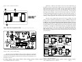
In a biamped system, low frequency audio power typically outweighs high
frequency power by a significant margin, depending on efficiency of the speakers.
For example, a biamped system might require 300 watts for the low end but only 100
watts or less for the high frequency drivers. This is because high frequencies convert
to acoustic energy much more efficiently than lows. So in order to avoid wasting
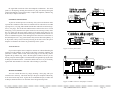
unused amplifier power, Mode 2 allows the low output of the crossover to drive both
amplifier channels, while the aux high output is used to drive a less powerful amplifier
for the high frequency drivers. If even more low frequency power is required, switch
to Mode 3 for bridged low out operation. Bridged output is taken from the two red
binding posts, with channel two as the (+) signal. Caution: never connect either red
binding post to ground!
The aux out jacks access the crossover outputs just prior to their respective
level controls, and although they are not affected by these controls, they contain all
of the respective processing of their filter, ie. 20Hz low-cut filter on the low output,
and phase and CD horn EQ on the high output. The aux outputs are pseudo-balanced
tip-ring-sleeve and while not electrically balanced, have the same common mode
rejection characteristics as full balanced lines, providing they terminate into a
balanced input.
Fc = 80Hz . . . . . . . . . . . . . . . . . . . . . . . . . . . . .Rf = 140KΩ
Ω∗
Fc = 160Hz . . . . . . . . . . . . . . . . . . . . . . . . . . . . Rf = 68KΩ∗
Ω∗
Fc = 500Hz . . . . . . . . . . . . . . . . . . . . . . . . . . . . Rf = 22KΩ∗
Fc = 750Hz . . . . . . . . . . . . . . . . . . . . . . . . . . . . Rf = 15KΩ
Ω∗
Fc = 1.2KHz . . . . . . . . . . . . . . . . . . . . . . . . . . . Rf = 10KΩ∗
Fc = 1.6KHz . . . . . . . . . . . . . . . . . . . . . . . . . . . Rf = 6.8KΩ
If you wish to choose a different crossover point, start with the desired
frequency and compute the following equation for Rf:
Fc = 1/ (8.88 x 10⁻⁸) Rf
Where Fc is the desired crossover point and Rf is the SIP network value. You
may have difficulty finding the correct SIPS at your local parts dealer, so if you
absolutely must have a different frequency than one we have available, consult
with the factory for possible further help.
PHASE
When two identical waveforms are superimposed over each other, or in
phase, they will simply add to each other and double in amplitude. Thus, each XR1 filter is 6dB down at the crossover point so that addition of both highpass and
lowpass filters yields a flat response through the crossover region (6dB is double
the voltage). Therefore, the signal coming out of the amplifier is summed flat
because the two filter outputs are electronically in phase with each other.
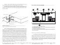
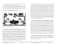
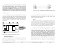
Figure 6: XR-1 connector and resistor network locations
FREQUENCY SELECTION
The XR-1 is supplied with three* sets of matched resistor SIPS which
correspond to popular crossover points. Each SIP contains four identical and
discrete resistors. The other selected values are available by calling the factory.
The values we have chosen are as follows:
Problems may occur when speaker voice coils are placed at a different
distance to any given set of ears. Since the high frequency driver is typically
located behind the woofer, identical signals at each driver (at the crossover
frequency) are converted to soundwaves which ultimately interact with each other
in the form of phase cancellation. In other words, while in-phase signals will add
to each other, out-of-phase signals will subtract. The degree to which they
subtract, or cancel, is determined by their phase relationship. O° means precisely
in phase, while 180° results in total cancellation. A 500Hz signal has a wavelength
of about two feet, so if the high frequency voice coil is offset from the woofer voice
coil by one foot, the two signals will be acoustically half of the waveform, or 180°,
out of phase. You can correct for this by changing the electrical phase of the high
frequency signal by 180° so that the high and low signals will be acoustically in
phase. Keep in mind that there are many other factors contributing to phase
distortion which we have little control over, such as horn construction and
materials, cabinet resonance, room reflections, even temperature and humidity.
○ ○ ○ ○ ○ ○ ○ ○ ○ ○ ○ ○ ○ ○ ○ ○ ○ ○ ○ ○ ○ ○ ○ ○ ○ ○ ○ ○ ○ ○ ○ ○ ○ ○ ○ ○ ○ ○ ○ ○ ○ ○ ○ ○ ○ ○ ○ ○ ○ ○ ○ ○ ○ ○ ○ ○ ○ ○ ○ ○ ○ ○ ○ ○ ○ ○ ○ ○ ○ ○ ○ ○ ○ ○ ○ ○ ○ ○ ○ ○ ○ ○ ○ ○ ○ ○ ○ ○
Ashly POWERCARD Owners Manual
Page 8
Ashly POWERCARD Owners Manual
Page 9