1
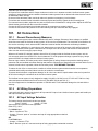
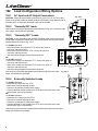
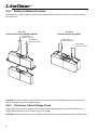
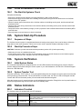
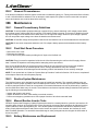
Installation Instructions
and
User Manual
For
100 Watt
Inverter
Power
System
Installation Instructions and User Manual For
LiteGear® 100 Watt Inverter Power System
Warning:
THIS PRODUCT CONTAINS CHEMICALS KNOWN TO THE STATE OF CALIFORNIA TO
CAUSE CANCER, BIRTH DEFECTS, AND/OR OTHER REPRODUCTIVE HARM.
THOROUGHLY WASH HANDS AFTER INSTALLING, HANDLING, CLEANING OR
OTHERWISE TOUCHING THIS PRODUCT.
READ AND FOLLOW ALL SAFETY
INSTRUCTIONS
IMPORTANT SAFEGUARDS
When using electrical equipment, you should always follow basic safety precautions,
including the following:
1. Read and follow all safety instructions.
2. Do not install the LiteGear system outdoors.
3. Do not let power supply cords touch hot surfaces.
4. Do not install near gas or electric heaters or in other high-temperature locations.
5. Use caution when servicing batteries. Battery acid can cause burns to skin and
eyes. If acid is spilled on skin or in the eyes, flush with fresh water and contact a
physician immediately.
6. Equipment should be mounted in locations where it will not be readily subjected to
tampering by unauthorized personnel.
7. The use of accessory equipment not recommended by the manufacturer may
cause an unsafe condition and may void the warranty.
8. Do not use this equipment for other than intended use.
9. All servicing of this equipment must be performed by qualified service personnel.
SAVE THESE INSTRUCTIONS
IMPORTANT SAFETY INSTRUCTIONS
The installation and use of this product must comply with all national, federal, state,
municipal, or local codes that apply.
Please read this manual thoroughly before operating the LiteGear Inverter System.
For technical assistance, contact Dual-Lite’s Systems Technical Support Center at
1-800-848-6439. Technicians are available during normal working hours (EST).
2
Table of Contents
Description
Page
100.Installation ...................................................................................................................................................................... 4-5
100.1 General Installation Requirements........................................................................................................................ 4
100.2 Cabinet Installation............................................................................................................................................................... 4
101.
AC Connections ............................................................................................................................................................. 5-6
101.1 General Precautionary Measures......................................................................................................................................... 5
101.2 AC Wiring Preparations......................................................................................................................................................... 6
101.3 AC Input Voltage Selection .................................................................................................................................................. 6
102.
Load Configuration Wiring Options ............................................................................................................................. 6-7
103.
Installing the Batteries and DC Wiring......................................................................................................................... 7-8
104.
Final Installation Checklist............................................................................................................................................... 9
105.
System Start-Up Procedure ............................................................................................................................................. 9
106.
System Verification........................................................................................................................................................... 9
200.
Status Indicators............................................................................................................................................................... 9
102.1 AC Input and AC Output Connections .................................................................................................................................. 6
102.2 "Normally ON" Loads ........................................................................................................................................................... 6
102.3 "Normally OFF" Loads ......................................................................................................................................................... 7
102.4 Externally Switched Loads ................................................................................................................................................... 7
103.1 General Precautionary Measures......................................................................................................................................... 7
103.2 Installation Considerations.................................................................................................................................................... 8
103.3 Battery Installation Procedure............................................................................................................................................... 8
103.4 Electronics Cabinet Voltage Check....................................................................................................................................... 8
104.1 Pre-Start-Up Systems Check................................................................................................................................................ 9
105.1 Sequence of Steps ............................................................................................................................................................... 9
105.2 Start-Up Procedure Steps..................................................................................................................................................... 9
106.1 Initial System Status ............................................................................................................................................................ 9
106.2 System Transfer Test............................................................................................................................................................ 9
200.1 Indicators Provided............................................................................................................................................................... 9
200.2 Unusual Circumstances...................................................................................................................................................... 10
300.Maintenance................................................................................................................................................................ 10-12
300.1 General Precautionary Measures....................................................................................................................................... 10
300.2 Final Shut Down Procedure................................................................................................................................................ 10
300.3 Routine System Maintenance............................................................................................................................................. 10
300.4 Manual Routine Inverter Tests............................................................................................................................................ 10
300.5 Battery Maintenance and Replacement ............................................................................................................................. 10
300.6 Important Safety Precautions ..............................................................................................................................................11
300.7 Replacement Fuses ............................................................................................................................................................11
300.8 Routine Battery Inspection and Maintenance......................................................................................................................11
300.9 Battery Replacement Procedure..........................................................................................................................................11
300.10 Battery Disposal ............................................................................................................................................................... 12
301.
Technical Service and Support...................................................................................................................................... 12
302.
Warranty Information...................................................................................................................................................... 12
301.1 Toll-Free Number................................................................................................................................................................ 12
302.1 Warranty ............................................................................................................................................................................. 12
3
100.Installation
100.1
General Installation Requirements
CAUTION:
LiteGear cabinets are very heavy. Check to assure that the chosen location is capable of safely bearing the load.
Cabinet Size: 18.375” W x 10.2” H x 8.25” D (46.6cm W x 25.9cm H x 21cm D)
Weight (including batteries): 70 lbs.
Install the LiteGear inverter system in a clean, cool, dry place with normal ventilation for human habitation.
LiteGear inverter systems are UL Listed for 20°C to 30°C (+68°F to +86°F) operation.
Battery performance and service life is maximized if the operating temperature is maintained at 25°C (77°F).
The air around the unit must be clean, dust-free, and free of corrosive chemicals or other contaminants. Do not place
the LiteGear inverter system or batteries in a sealed room or container.
100.2
Cabinet Installation
CAUTION:
Do not drill into the cabinet; drill filings may damage the unit and prevent it from operating. If additional or larger entry
points are needed, use a chassis punch to enlarge the appropriate knockout. Do not add unnecessary knockouts.
Remove the electronics module by removing the four screws on the right side of the cabinet. (The inverter cabinet
should be installed without the batteries inside.)
The LiteGear® units are supplied with two keyhole knockouts for wall mounting. See Figure 100-1. Necessary
hardware to fasten the cabinet to the wall is to be supplied by the installing contractor.
Please refer to the following illustrations.
Fig. 100-1
Surface Wall Mount
(Cabinet should be empty
before mounting)
Fig. 100-2
Recessed Wall Mount
(Cabinet should be empty
before mounting)
Fig. 100-3
Recessed Ceiling Mount
See Fig. 100-4 for
chain/cable note
S hooks
Use 1/4" lag screws to
mount cabinet to studs
(choose most convenient
pair of vertical knockouts)
4
Add shims
to one side if
both sides are
to be secured
Add brace
to support
cabinet
Secure cabinet to
studs with screws
through knockouts
Install the input and output conduits.
AC Input service conductors and AC Output conductors must be run in separate conduits. LiteGear inverter system
emergency output circuits must be installed in dedicated conduit systems and not shared with other electrical circuits
as described in NEC 700-9(b).
Be sure to follow all federal, state, and local codes as it pertains to emergency circuit raceways.
For surface and recessed models reinstall the electronics plate and securely tighten the four mounting nuts.
For recessed mount models, adjust the trim plate to fit flush to the finished wall or ceiling surface. Adjust the LED/Test
Switch bracket to be flush with the cover when installed.
Connect the LEDs to the printed circuit board ensuring the connectors are properly aligned.
Connect the test switch to the printed circuit board ensuring both pin connectors are fully engaged.
101. AC Connections
101.1
General Precautionary Measures
All LiteGear inverter system units contain hazardous AC and DC voltages. Because of these voltages, a qualified
electrician must install the LiteGear inverter system, AC line service, and batteries. The electrician must install the AC
line service according to local, state and NEC codes and must be familiar with batteries and battery installation.
Before installing, maintaining, or servicing the unit, always remove or shut off all sources of AC and DC power and
shut off the LiteGear inverter system. Disconnect AC line input at the service panel and disconnect the batteries to
make sure the unit will not supply output voltage.
Whenever AC and/or DC voltage is applied, there will be AC voltage inside the LiteGear inverter system unit; the
unit can supply power from the AC line or from its batteries. To avoid equipment damage or personal injury, always
assume that there is voltage inside the LiteGear inverter system.
Remove rings, watches, and other jewelry before installing the AC wiring. Always wear protective clothing and eye
protection and use insulated tools when working near batteries. Whenever an energized unit is serviced with the cover
removed, electric shock is possible; follow all local safety codes. TEST BEFORE TOUCHING!
To reduce the risk of fire or electric shock, install the LiteGear inverter system and the batteries in a temperaturecontrolled and humidity-controlled indoor area free of conductive contaminants.
To prevent electrical shock or equipment damage, for all units, insure the AC input breakers at the service panel are
all off before making AC connections to the LiteGear inverter system.
The LiteGear inverter system is only designed to supply 120 VAC in/120 VAC out or 277 VAC in/277 VAC out. Only
authorized persons should disconnect AC to the unit. (See NEC 700-20 and 700- 21.)
Use of this equipment for simultaneous operation of 120VAC and 277VAC loads will damage the unit and void the
warranty.
101.2
AC Wiring Preparations
If not previously done, remove knockouts for AC Input and AC Output in the LiteGear inverter system and install input
and output conduits per section 100.2
101.3
AC Input Voltage Selection
The battery charger transformer has two input leads:
black = 120VAC
orange = 277VAC
Select proper AC input lead for the application.
Refer to Fig. 102-1.
For 120VAC input:
• Black – Connect to FT22
• Orange – Remove “push on” connector and cap off using appropriate mechanical
connector
OR
For 277VAC input:
• Orange – Connect to FT23
• Black - Remove “push on” connector and cap off using appropriate mechanical connector
5
102. Load Configuration Wiring Options
102.1
AC Input and AC Output Connections
Fig. 102-1
CAUTION: Torque all terminal block connections to 4.4 to 5.3 in-lb. (0.5 to 0.6 Nm.)
Failure to do so may create an unsafe condition or fire hazard. Only "Normaly ON" or
"Normally OFF" or "Externally Switched" loads can be selected.
120V
IN
120V IN
FT20
COM IN
FT21
COM OUT
COM
OUT
FT19
Fig. 102-2
Fig. 102-3
Externally Switched Loads
For 120VAC Operation:
• Disconnect the black wire from FT22.
• Remove the terminal and strip the wire.
JUMPER
JUMPER
• Connect to unswitched 120VAC power supply.
• Connect switched 120VAC power to the 120V input connection of the input terminal block (pins not numbered).
OR
For 277VAC operation:
• Disconnect the orange wire from FT23.
• Remove the terminal and strip the wire.
• Connect to unswitched 277VAC power supply.
• Connect switched 277VAC power to the 277V input connection of the input terminal block (pins not numbered).
Connect utility and load wires to appropriate terminal blocks and ensure the input,
output, and chassis are grounded.
J2
J1
120V
OUT
FT18
FT16
FT14
For 120VAC Operation:
• Remove the black wire lead from FT16, remove the “push on” connector, and strip the end.
• Remove the red wire lead from FT14, remove the “push on” connector, and strip the end.
• Join them using an approved mechanical connector.
OR
For 277VAC operation:
• Remove the orange wire lead from FT17, remove the “push on” connector, and strip the end.
• Remove the orange wire lead from FT15, remove the “push on” connector, and strip the end.
• Join them using an approved mechanical connector.
6
277V IN
FT22
“Normally OFF” Loads
Connect utility and load to appropriate terminal blocks and ensure the input,
output, and chassis are grounded.
277V
IN
COM
IN
CAUTION: To use this product with normally off lighting loads requires rewiring the
circuit board to bypass an internal relay. This process should only be performed by
qualified personnel. Refer to Fig. 102-1.
102.4
FT17
Connect utility and load to appropriate terminal blocks per Fig. 102-1 and ensure the
input, output, and chassis are grounded.
102.3
FT23
“Normally ON” loads
FT15
102.2
277V
OUT
120V OUT
277V OUT
Externally switched loads can be switched per Fig. 102-4. Connect utility and load wires to appropriate terminal
blocks per Fig. 102-1 and ensure the input, output and chassis are grounded
Fig. 102-4
103. Installing The Batteries and DC Wiring
103.1
General Precautionary Measures
A qualified electrician who is familiar with battery systems and required precautions must install and service the
batteries. Any battery used with this unit shall comply with the applicable requirements for batteries in the standard
for emergency lighting and power equipment, UL 924. Cabinets are designed to be used with, and batteries must
be replaced with identical cells or a Dual-Lite approved equivalent. If using substitute batteries not supplied by DualLite, the unit’s UL listing will be void, and the equipment may fail to perform properly. The installation must conform to
national and local codes as well. Keep unauthorized personnel away from batteries.
Wear protective clothing, eye-wear, rubber gloves and boots. Batteries contain corrosive acids or caustic alkalis and
toxic materials and can rupture or leak if mistreated. Remove rings and metal wristwatches or other metal objects and
jewelry. Don’t carry metal objects in pockets where the objects can fall onto the batteries or into the LiteGear inverter
system.
Tools must have insulated handles so that they will not short battery terminals. Do not allow a tool to short a battery
terminal to another battery terminal or to the cabinet at any time. Do not lay tools or metal parts on top of the batteries,
and do not lay any objects where they could fall onto the batteries or into the cabinet.
Install the batteries as shown on the battery wiring diagram provided in this manual with the cables provided. When
connecting cables, never allow a cable to short across a battery’s terminals, the string of batteries, or to the cabinet.
Keep the cables away from any sharp metal edges.
Install the battery cables so they cannot be pinched by the LiteGear inverter system’s cover.
Where conductors may be exposed to physical damage, protect conductors in accordance with NEC requirements.
Full voltage and current are always present at the battery terminals. The batteries used in this system can produce
dangerous voltages, extremely high currents, and possible risk of electric shock. Batteries may cause severe injury if
the terminals are shorted together or to ground (earth). Be extremely careful to avoid electric shock and burns caused
by contacting battery terminals or shorting terminals during battery installation. Do not touch uninsulated battery
terminals.
103.2
Installation Considerations
This section explains how to install the LiteGear system’s batteries and cables. A qualified electrician who is familiar
with battery installations and applicable building and electrical codes must install the batteries.
7
103.3
Battery Installation Procedure
Place electronics module in cabinet, turned 90° from original orientation as shown in Fig. 101-1 for easy access to
wire connections.
Fig. 103-1
Surface and Recessed Wall Mount Models
Blue Leads to
PCT1 B- on PCB
Red Leads to
PCT3 B+ on PCB
Fig. 103-2
T-Grid Recessed Ceiling Model
Blue Leads to
PCT1 B- on PCB
Red Leads to
PCT3 B+ on PCB
CAUTION: Be careful to observe correct polarity on the battery terminals. Illustrations are given as a guide only;
polarity markings may vary from battery to battery.
103.4
Electronics Cabinet Voltage Check
Using a digital volt-ohm meter, check for correct nominal battery voltage between battery NEG and POS wires.
Voltage reading should be 12 VDC ±10% of system DC voltage.
CAUTION: Ensure all connections are fully engaged. Failure to do so may create an unsafe condition or fire hazard.
8
104. Final Installation Checklist
104.1
Pre-Start-Up Systems Check
Complete the following:
• Ensure the LiteGear Inverter cabinet is securely fastened to a wall or other structure.
• Ensure that the input circuit breaker in the building service panel serving as the AC disconnect to the LiteGear
system is in the OFF position.
• Check for proper ground connections in the LiteGear cabinet, the building service panel, and the external load
distribution panel.
• Check for any loose wiring connections in the LiteGear cabinet, the building service panel, and the external load
distribution panel.
• Check that correct nominal battery voltage (12 VDC) is present in the LiteGear cabinet between the battery NEG
and POS wires.
• Securely fasten cover and ensure no wires are pinched.
105. System Start-Up Procedure
105.1
Sequence of Steps
The LiteGear inverter system is a sophisticated electronic backup power supply. Care must be taken to follow the
steps below in their exact sequence. Failure to do so can result in possible equipment damage or failure.
105.2
Start-Up Procedure Steps
CAUTION: Familiarize yourself with the shut down procedure (section 300.1) before proceeding.
• Make sure the cover is installed and secured.
• At the building service panel, energize the circuit breaker serving as the AC disconnect to the LiteGear system.
• The system should turn “ON”; the green “AC-ON” LED will illuminate.
106. System Verification
106.1
Initial System Status
The connected load should be energized and the “AC ON” LED should be illuminated (green). Allow a minimum
24-hour charge period before testing the inverter system. If you need assistance, call Dual-Lite’s Technical Support
Center at 1-800-848-6439.
106.2
System Transfer Test
Press the momentary “TEST” switch or, for a prolonged discharge test, de-energize the service panel circuit breaker
serving as AC input circuit breaker. The unit will transfer to inverter mode, the "AC On" LED will extinguish and the
"Inverter ON" LED will illuminate (amber). All connected loads should be energized.
Allow the inverter to run for several minutes or until satisfied with its operation. Energize the service panel breaker to
end the prolonged discharge test and return the unit to standby mode.
200. Status Indicators
200.1
Indicators Provided
The LiteGear system is equipped with two LED indicators:
LED Display
System Mode
No Color
Off
Amber
Inverter-ON
Green
AC-ON/Charging
Reason
• No AC power
• Low Voltage Battery Disconnect circuit activated following extended power outage
• Batteries disconnected
• Test
• Loss of utility
• Utility applied, branch feeder circuit breaker energized
9
200.2
Unusual Circumstances
If an abnormal condition is detected, please contact the local Hubbell Lighting, Inc. Factory Authorized Service Center,
or call 1-800-848-6439 for assistance. Do not attempt to make repairs; the system is fed from more than one power
source and extreme care must be taken before servicing.
300.Maintenance
300.1
General Precautionary Guidelines
CAUTION: To avoid possible equipment damage or personal injury, assume that there is AC voltage present inside
the LiteGear inverter cabinet when AC input power or DC battery voltage is present. The inverter is capable of providing output voltage from the batteries even when there is no AC input line voltage. When AC input voltage is present,
the unit can provide output voltage even when the batteries are disconnected.
CAUTION: AC and DC voltage will be present inside the unit until both the line AC and the batteries are disconnected.
CAUTION: Do not touch components inside the unit. DC voltage is always present at the batteries and the battery
cables.
300.2
Final Shut Down Procedure
• Remove the unit’s cover.
• Disconnect the batteries.
• Turn off the service panel breaker providing the AC input to the LiteGear unit.
CAUTION: Energy is stored in capacitors inside the unit. After disconnecting the unit from the AC supply, allow at
least 5 minutes for capacitors to discharge before attempting service procedures.
If the service technician does not need to access the inside of the unit, keep the unit's cover securely installed.
If the unit will be shut off for an extended period of time, recharge the batteries every 60 to 90 days.
CAUTION: The batteries will be damaged and the warranty voided if the batteries are not routinely recharged.
NOTE: To turn power back on, follow the “System Start-up Procedure” outlined in Section 105. Be sure to complete all
of the steps to assure the unit will operate properly.
300.3
Routine System Maintenance
The LiteGear inverter unit is designed to provide years of trouble-free operation. The manually-initiated cycles are
designed to ensure proper operation of the unit's batteries and inverter. The unit does require some routine attention
to assure peak performance. Dual-Lite recommends a Preventative Maintenance check be performed by a qualified
service technician at least every six months. The technician must observe important safety precautions while performing the following recommended tasks:
• Inspect and clean the unit interior
• Inspect all batteries for leaks, case swelling or terminal corrosion
• Perform an emergency operation test to check proper function of all critical connected loads
300.4
Manual Routine Inverter Tests
300.5
Battery Maintenance and Replacement
NFPA101 requires that Emergency Lighting Equipment be tested on a monthly basis for a period of not less than 30
seconds, and a minimum of 90 minutes once a year. We strongly recommend these guidelines be followed to insure
system readiness, and to prolong battery life. The LiteGear system incorporates a test switch to facilitate monthly
testing. Simply depress the button and hold to test the inverter at anytime. Once released, the LiteGear will revert
back to standby operation. For annual 90-minute discharge or other prolonged tests, de-energize the AC breaker at
the service panel.
10
This section provides precautions for qualified service personnel working with unit batteries.
300.6
Important Safety Precautions
CAUTION: A battery can present a risk of electrical shock and high short circuit current. Battery replacement should
only be performed by qualified service personnel familiar with battery systems. All safety precautions outlined at the
beginning of this section must be observed when servicing, maintaining or replacing batteries
• A qualified electrician who is familiar with battery systems and required precautions must install and service the
batteries. Any battery used with this unit shall comply with the applicable requirements for batteries in the standard for
emergency lighting and power equipment, UL 924. Cabinets are designed to be used with, and batteries must be replaced by identical cells or a Dual-Lite approved equivalent. If using substitute batteries not supplied by Dual-Lite, the
unit’s UL listing will be void, and the equipment may fail to perform properly. The installation must conform to national
and local codes as well. Keep unauthorized personnel away from batteries
The service technician must take these precautions:
• Wear protective clothing, eye-wear, rubber gloves and boots. Batteries contain corrosive acids or caustic alkalis and
toxic materials, and can rupture or leak if mistreated.
• Remove rings and metal wristwatches or other metal objects and jewelry. Don’t carry metal objects in pockets
where the objects can fall onto the batteries or into the LiteGear inverter system cabinet.
• Tools must have insulated handles so that they will not short battery terminals. Do not allow a tool to short a battery
terminal to another battery terminal or to the cabinet at any time. Do not lay tools or metal parts on top of the batteries,
and do not lay any objects where they could fall onto the batteries or into the cabinet.
• Install the batteries as shown on the battery wiring diagram provided in this manual. When connecting cables, never
allow a cable to short across a battery’s terminals, the string of batteries, or to the cabinet.
• Keep the cables away from any sharp metal edges.
• Install the battery cables so they cannot be pinched by the LiteGear inverter system’s cover.
• Where conductors may be exposed to physical damage, protect conductors in accordance with NEC requirements.
• If replacing batteries or repairing battery connections, follow the procedure in this manual to shut down the LiteGear
inverter system and remove both AC and DC input power.
• Full voltage and current are always present at the battery terminals. The batteries used in this system can produce
dangerous voltages, extremely high currents, and possible risk of electric shock. Batteries may cause severe injury if the
terminals are shorted together or to ground (earth). Be extremely careful to avoid electric shock and burns caused by
contacting battery terminals or shorting terminals during battery installation. Do not touch uninsulated battery terminals.
300.7 Replacement Fuses
DC fuse:
BATT. (+) INPUT
1) Bussmann MDL-15
300.8
AC Fuse:
120V OUTPUT
P/N 93014998
250V, 1.5A FAST
1) BUSSMANN GLR1.5A
2) CONQUER ELEC. LTD. AFE 1.5A 250V
AC Fuse:
277V OUTPUT
P/N 93015004
600V, 1A FAST
1) BUSSMANN GLR1A
2) LITTLEFUSE KLK 1
Routine Battery Inspection and Maintenance
Sealed Lead-Calcium Batteries
Sealed Lead-Calcium batteries are the most common type of battery used in standby power supply equipment. By
design it is as maintenance free as a battery can be. These batteries provide one of the most reliable and carefree
inverter systems available today. It is recommended, however, that some simple steps be taken to increase system
life and maximize reliability:
• Monthly: check the system for proper operation.
• Quarterly: check the batteries for deformities in the cases and terminal corrosion. Any defective batteries should be
replaced. All corroded terminals, regardless of how slight the condition, are to be cleaned and retightened at once to
prevent failure of the entire battery bank.
• Yearly: Check all battery connections for tightness and proper torque specifications.
11
300.9
Battery Replacement Procedure
WARNING: Always use the same quantity and type of battery as replacements.
Substituting batteries not supplied by Dual-Lite will void the UL listing of the system and may cause equipment failure. To ensure the superior performance of your LiteGear inverter system and to maintain proper charger operation,
replace spent batteries only with Dual-Lite cells having the same part number, voltage and ampere-hour rating as the
original batteries.
• Follow the proper shut down procedure as described in Section 300.2.
• Disconnect the battery bank beginning with the battery-to-battery connectors. These cables tie the batteries
installed on the same shelf together.
• Remove the inter-tier cables. These cables connect the batteries located on different shelves together.
• Remove the batteries from the cabinet. Batteries can be very heavy; use proper lifting methods when removing
batteries.
• Install new batteries following the instructions outlined in Section 103.
300.10 Battery Disposal
WARNING:
• Do not dispose of batteries in a fire; the batteries could explode.
• Do not open or mutilate batteries.
• Released electrolyte is highly toxic and harmful to the skin and eyes.
CAUTION: Batteries contain lead. Many state and local governments have regulations about used battery disposal.
Please dispose of the batteries properly. For help, contact the Dual-Lite Technical Support Center.
301. Technical Service and Support
301.1
Toll-Free Number
During or after installation, Dual-Lite’s Systems Technical Support Center is available to provide expert assistance.
Our service representatives are available to answer customers’ questions and recommend solutions to installation or
operating problems.
A toll-free phone has been established for LiteGear technical assistance. 1-800-848-6439.
Service representatives are available during normal working hours (EST).
302. Warranty Information
CAUTION:
• Lengthy storage of batteries will cause irreversible damage to the cells.
• Failure to connect LiteGear inverter system batteries to an energized charging circuit within 90 days from the date of
shipment will void the battery warranty.
302.1Warranty
The system is guaranteed, under normal and proper use, against defects in workmanship and materials for a period of
three years from the date of shipment.
Batteries supplied as part of the system are covered under a warranty as described below:
• Full: 3 years
• Pro-Rata: 7 years
Dual-Lite • www.dual-lite.com
A Hubbell Lighting, Inc. brand with representatives’ offices in principal cities throughout North America.
Copyright © Hubbell Lighitng, Inc., All Rights Reserved • Specifications subject to change without notice. • Printed in U.S.A.
12
93015049 D 1/15