1
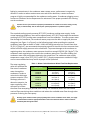
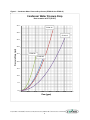
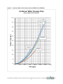
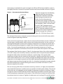
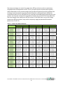
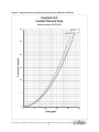
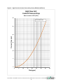
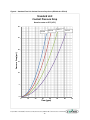
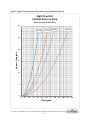
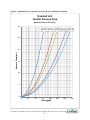
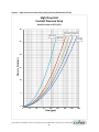
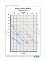
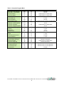
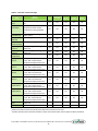
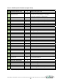
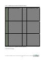
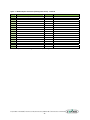
when piping is overhead with a total run length over 90 feet (27 M) there should be a valve in the supply line and an inverted P trap with a vacuum break valve installed as shown in Figure 3. Figure 3 – Recommended Overhead Piping Figures 4 through 9 (on the following 12 inches above highest pages) provide the pressure drop point in piping system through the evaporator and chilled water piping associated with the 1/2 inch vacum break valve chiller. Use this information for assistance when sizing a chilled water pump. Nominal chilled water flow rates are provided in Table 2 and are based Check valve on a 10°F (18°C) range across the evaporator at 50°F (10°C) LWT and 85°F NOTE: (29.4°C) entering condenser water. If piping is above chiller and exceeds 90 feet in total length, install an inverted P-trap and vacuum break valve in return line and add a check valve to the Pump curves for typical optional pumps supply line. with 60 Hz power are in shown in Figure 10 – EP2 Series Pump Curves. The minimum flow rates are required to prevent fouling and to ensure the chiller stays within normal refrigerant operating conditions. If the process flow requirement is lower than the minimum flow limitation shown in Table 2 (on the next page), multiple smaller chillers may be used. Another alternative is to use a primary pumping loop designed for lower flow at a higher temperature rise through the process and a secondary pumping loop designed for a higher flow and lower temperature drop through the chiller. If a secondary pumping loop is used, maintain the mixed temperature of coolant entering the evaporator at a minimum of at least 5°F (2.8°C) above the setpoint of the chiller. The maximum flow limitation shown in Table 2 is the theoretical limits of the chiller based upon a 5°F (2.8°C) drop across the chiller; however, these flows result in impractical pressure drops through the chiller and are therefore not likely for a system design. If the process flow requirement is higher than the maximum flow limitation, a bypass around the chiller may be used. Another alternative is to use a primary pumping loop designed for higher flow and lower temperature rise through the process and a secondary pumping loop designed for lower flow and higher temperature drop through the chiller. If a secondary pumping loop is used, maintain the mixed temperature of coolant entering the chiller at a minimum of at least 5°F (2.8°C) above the setpoint of the chiller. The use of varying chiller flows is sometimes necessary; however, it is highly recommended to use a dedicated evaporator circulation pump to provide increased system stability. The controls of the chiller are very adaptable and are capable of adjusting to variations in the flow of water through the system and will load and unload compressor(s) as needed to maintain tight control of the leaving water temperature of the system. If the chiller flow is varied, the minimum fluid loop volume must be in excess of 3 gallons of coolant per ton of cooling (3.2 L per kW) and the Corporate Office: 724.584.5500 Instant Access 24/7 (Parts and Service): 800.458.1960 Parts and Service: 814.437.6861 9