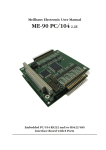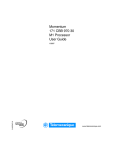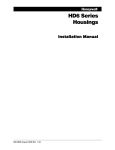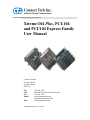
1
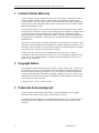
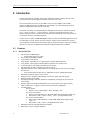
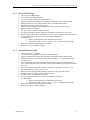
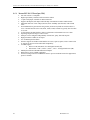
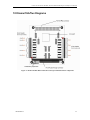
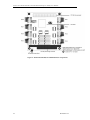
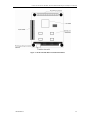
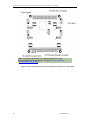
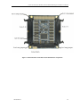
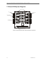
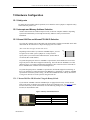
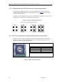
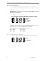
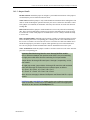
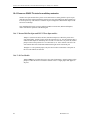
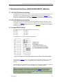
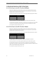
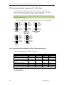
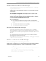
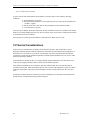
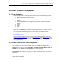
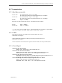
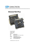
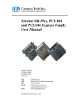
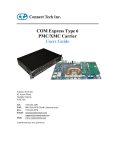
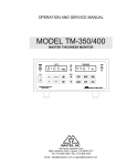
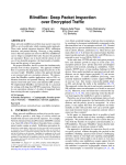
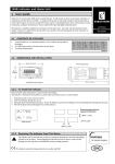
Xtreme/104 Plus, PCI-104 and PCI/104 Express Family User Manual Connect Tech Inc. 42 Arrow Road Guelph, Ontario N1K 1S6 Tel: Toll: Fax: Email: Web: 519-836-1291 800-426-8979 (North America only) 519-836-4878 [email protected] [email protected] www.connecttech.com CTIM-00029 Revision 0.13 Dec 6, 2012 Connect Tech Xtreme/104-Plus, PCI-104 and PCI/104 Express Family User Manual 1 Limited Lifetime Warranty Connect Tech Inc. provides a lifetime warranty for all of our products. Should this product, in Connect Tech Inc.’s opinion, fail to be in good working order during the warranty period, Connect Tech Inc. will, at our option, repair or replace this product at no charge, provided that the product has not been subjected to abuse, misuse, accident, disaster or non Connect Tech Inc. authorized modification or repair. You may obtain warranty service by delivering this product to an authorized Connect Tech Inc. business partner or directly to Connect Tech Inc. along with proof of purchase. Product returned to Connect Tech Inc. must be pre-authorized by Connect Tech Inc. with an RMA (Return Material Authorization) number marked on the outside of the package and sent prepaid, insured and packaged for safe shipment. Connect Tech Inc. will return this product by prepaid ground shipment service. The Connect Tech Inc. lifetime warranty is defined as the serviceable life of the product. This is defined as the period during which all components are available. Should the product prove to be irreparable, Connect Tech Inc. reserves the right to substitute an equivalent product if available or to retract lifetime warranty if no replacement is available. The above warranty is the only warranty authorized by Connect Tech Inc. Under no circumstances will Connect Tech Inc. be liable in any way for any damages, including any lost profits, lost savings or other incidental or consequential damages arising out of the use of, or inability to use, such product. 2 Copyright Notice The information contained in this document is subject to change without notice. Connect Tech Inc. shall not be liable for errors contained herein or for incidental consequential damages in connection with the furnishing, performance, or use of this material. This document contains proprietary information that is protected by copyright. All rights are reserved. No part of this document may be photocopied, reproduced, or translated to another language without the prior written consent of Connect Tech Inc. Copyright 1997 - 2012 by Connect Tech Inc. 3 Trademark Acknowledgment Connect Tech Inc. acknowledges all trademarks, registered trademarks and/or copyrights referred to in this document as the property of their respective owners. Not listing all possible trademarks or copyright acknowledgments does not constitute a lack of acknowledgment to the rightful owners of the trademarks and copyrights mentioned in this document. 2 Revision 0.12 Connect Tech Xtreme/104 Plus, PCI-104 and PCI/104 Express Family User Manual 4 Table of Contents 1 2 3 4 5 6 7 8 9 10 11 12 13 14 15 16 17 18 Limited Lifetime Warranty ............................................................................................................................... 2 Copyright Notice ............................................................................................................................................... 2 Trademark Acknowledgment ............................................................................................................................ 2 Table of Contents .............................................................................................................................................. 3 4.1 List of Figures ....................................................................................................................... 4 4.2 List of Tables ......................................................................................................................... 5 Revision Changes.............................................................................................................................................. 6 Customer Support Overview ............................................................................................................................. 6 Contact Information .......................................................................................................................................... 6 Conventions used in this manual ....................................................................................................................... 7 Introduction ....................................................................................................................................................... 8 9.1 Features................................................................................................................................ 8 9.1.1 Xtreme/104-Plus ................................................................................................................ 8 9.1.2 Xtreme/104-Plus Opto ....................................................................................................... 9 9.1.3 Xtreme/104-Express Opto.................................................................................................. 9 9.1.4 Xtreme/PCI-104 12 Port Opto (XIG)................................................................................10 Xtreme/104-Plus Diagrams ..............................................................................................................................11 Xtreme/104 Express Diagrams .........................................................................................................................16 Xtreme/PCI104 12 Port Opto Diagrams ...........................................................................................................17 Xtreme/104 Installation Overview ...................................................................................................................18 Hardware Installation .......................................................................................................................................18 14.1 ESD Warning ...................................................................................................................... 18 14.2 Installing Xtreme/104-Plus or Xtreme/104PCI Cards Into Your System ..................................... 18 Hardware Configuration...................................................................................................................................19 15.1 Safety note .......................................................................................................................... 19 15.2 Interrupts and Memory Address Selection............................................................................... 19 15.3 Xtreme/104 Plus and Xtreme/PCI-104 ID Selection ................................................................. 19 15.3.1 Xtreme/104 Plus ID Selection Using the Rotary Switch ...................................................19 15.3.2 Xtreme/104 Plus and /PCI-104 ID Selection Using the Jumper Block .............................20 15.3.3 XIG 12 Port Opto Selection Using the Miniature Rotary Switch (RevC) .........................20 Electrical Interfaces Xtreme/104 Plus and Express (RS-232/422/485 and RS-423 Models) ...........................21 16.1 RS-232 Electrical Interface ................................................................................................... 21 16.2 RS-422/485 Electrical Interface............................................................................................. 21 16.2.1 Full Duplex 4-Wire Mode .................................................................................................21 16.2.2 Half Duplex 2-Wire Mode ................................................................................................21 16.2.3 Multi-drop 4-Wire Mode ..................................................................................................21 16.2.4 Line Bias and Termination ...............................................................................................21 16.3 Jumper Block Settings .......................................................................................................... 22 16.3.1 Four and Eight Port Xtreme/104 Plus models ..................................................................22 16.3.2 Sixteen Port Xtreme/104 Plus models ...............................................................................22 16.3.3 Jumper Details .................................................................................................................23 16.4 Power-on RS485 Tri-state for multidrop networks. .................................................................. 24 16.4.1 Xtreme/104-Plus Opto and XIG 12 Port Opto models: ....................................................24 16.4.2 16 Port Models .................................................................................................................24 Electrical Interfaces (RS-232/422/485/TTL Models) .......................................................................................25 17.1 RS-232/TTL Electrical Interface ............................................................................................ 25 17.2 RS-422/485 Electrical Interface............................................................................................. 25 17.3 Jumper Block Settings .......................................................................................................... 25 Electrical Interfaces XIG 12 Port Opto ............................................................................................................26 18.1 I/O Port Power for the XIG 12 Port Rev A/B Models ............................................................... 26 18.2 I/O Port Power for the XIG 12 Port Rev C Models .................................................................. 26 18.3 Line Modes XIG 12 Port Opto ............................................................................................... 27 18.3.1 Low Power Shutdown .......................................................................................................27 18.3.2 Slow Slew Rate (Rev C models) ........................................................................................27 18.3.3 RS-232 Electrical Interface ..............................................................................................27 18.3.4 Full Duplex 4-Wire RS485 ...............................................................................................27 18.3.5 Multi-drop 4-WireRS485 ..................................................................................................27 18.3.6 Half Duplex 2-Wire RS485 ...............................................................................................27 18.3.7 Line Bias/Termination ......................................................................................................27 Revision 0.11 3 Connect Tech Xtreme/104-Plus, PCI-104 and PCI/104 Express Family User Manual Line Interface Mode Jumpers for XIG 12 Port Opto ................................................................ 28 18.4.1 Line Interface Mode Jumpers for XIG 12 Port Opto (table view) ....................................28 18.5 Bias and Termination Resistors XIG 12 Port Opto .................................................................. 29 18.6 Power-on Tri-state for XIG 12 Port Opto ............................................................................... 29 18.7 Power considerations for the XIG 12 Port Opto ...................................................................... 29 Thermal Considerations ...................................................................................................................................30 Driver Software Configuration .........................................................................................................................31 20.1 Driver Installation ............................................................................................................... 31 20.2 RS-485 Multidrop 2 and 4 wire configuration ......................................................................... 31 Connectors/Pinouts ..........................................................................................................................................32 21.1 40 Pin Connector Pin Numbering .......................................................................................... 32 21.2 80 Pin Connector Pin Numbering .......................................................................................... 32 21.3 Xtreme/104 Plus RS423 ........................................................................................................ 33 21.4 Xtreme/104 Plus RS-232/422/485 .......................................................................................... 34 21.5 Xtreme/104 Plus 16 Port....................................................................................................... 35 21.6 Xtreme/104 Plus Opto 2 & 4 Port, Xtreme/104-Express Opto 8 Port ......................................... 36 21.7 XIG 12 Port Opto................................................................................................................. 37 Cable Pinouts ...................................................................................................................................................38 22.1 Single, Quad and Octal cables .............................................................................................. 38 22.2 Xtreme/PCI-104 12 Port Opto ............................................................................................... 38 22.3 Xtreme/104 Plus RS232/485/TTL model ................................................................................. 39 Wiring Examples..............................................................................................................................................40 23.1 RS232 Wiring Example ......................................................................................................... 40 23.2 RS423 Wiring Example ......................................................................................................... 40 23.3 RS-422/485 Wiring Examples ................................................................................................ 41 Specifications ...................................................................................................................................................42 24.1 Operating Environment ........................................................................................................ 42 24.2 Power Requirements ............................................................................................................ 42 24.3 PC/104 Bus Interface ........................................................................................................... 42 24.4 PCIe/104 Bus Interface......................................................................................................... 42 24.5 PCI-104 .............................................................................................................................. 42 24.6 Dimensions ......................................................................................................................... 42 24.7 Communications .................................................................................................................. 43 24.7.1 Baud Rates most models: ..................................................................................................43 24.7.2 UARTs ..............................................................................................................................43 24.7.3 Control Signals .................................................................................................................43 24.8 Certification ........................................................................................................................ 44 Part Numbers ...................................................................................................................................................44 18.4 19 20 21 22 23 24 25 4.1 List of Figures Figure 1: Xtreme/104-Plus RS-232/422/485 4 and 8 port models hardware components ............................11 Figure 2: Xtreme/104-Plus RS-423 Model Hardware Components ..............................................................12 Figure 3: Xtreme/104-Plus RS-232/422/485/TTL Models .............................................................................13 Figure 4: Xtreme/104-Plus Opto RS-232/422/485 Hardware Components (4 Port Model) .........................14 Figure 5: Xtreme/104-Plus 16 Port RS-232/422/485 Hardware Components ..............................................15 Figure 6: Xtreme/104-Express Opto 4 and 8 port Hardware Components ...................................................16 Figure 7: XIG 12 Port Opto Rev A/B Hardware Components ......................................................................17 Figure 8: XIG 12 Port Opto Rev C Hardware Components .........................................................................17 Figure 9: Rotary Switch ID Selection ............................................................................................................19 Figure 10: Jumper Settings for ID Selection .................................................................................................20 Figure 11: Rotary Switch ID Selection ..........................................................................................................20 Figure 12: Example of Various Jumper Block Settings for RS-232/422/485 Models ....................................22 Figure 13: Example of Various Jumper Block Settings for RS-232/422/485 Models ....................................22 Figure 14: Examples of Various Jumper Block Settings for RS-232/422/485/TTL Models ..........................25 Figure 15: Examples of Various Jumper Block Settings for the 12 Port Opto model ...................................28 Figure 16: 40 Pin Connector: Pin Numbering ..............................................................................................32 Figure 17: 80 Pin Connector: Pin Numbering ..............................................................................................32 Figure 18: RS-232 Wiring Diagram ..............................................................................................................40 Figure 19: RS-423 Wiring Diagram ..............................................................................................................40 4 Revision 0.12 Connect Tech Xtreme/104 Plus, PCI-104 and PCI/104 Express Family User Manual Figure 20: RS-422/485 Wiring Diagram (4 Wire) ........................................................................................41 Figure 21: RS-422/485 Wiring Diagram (4 Wire Multidrop) .......................................................................41 Figure 22: RS-422/485 Wiring Diagram (2 Wire) ........................................................................................41 4.2 List of Tables Table 1: I/O Signal Assignments for RS-423 Models ....................................................................................33 Table 2: I/O Signal Assignments for RS-232/422/485 Models) .....................................................................34 Table 3: I/O Signal Assignments for 16 Port model ......................................................................................35 Table 4: 10 Pin R/A Port Header Pinouts on Opto Models .........................................................................36 Table 5: 10 Pin R/A Port Header Pinouts on 12 Port Opto Models .............................................................37 Table 6: DB-9 Male Cable Pinouts ...............................................................................................................38 Table 7: CBG067 DB-9 Male Cable Pinouts for 12 Port Opto model ..........................................................38 Table 8: RS-232/TTL Px1 Right Angled Header Pinouts (CAG104 Compatible) .........................................39 Table 9: RS-485 Px2 Vertical Header Pinouts ..............................................................................................39 Table 10: Multipurpose I/O (MPIO) Header Pinout (Direct Connection to UART) .....................................39 Revision 0.11 5 Connect Tech Xtreme/104-Plus, PCI-104 and PCI/104 Express Family User Manual 5 Revision Changes Rev 0.12 Date Dec 6, 2012 Change Updated information in regards to the XIG 12 Port Opto. - Added new picture for Rev C model, including power jumper changes. - Restated power consumption for the XIG 12 Port Opto, added typical and max for RS485. - Low Power shutdown feature has been removed, Slow Slew rate feature added. See section Low Power Shutdown for more detail. Added new section about thermal considerations for Optically Isolated boards. 6 Customer Support Overview If you experience difficulties after reading the manual and/or using the product, contact the Connect Tech Inc. reseller from which you purchased the product. In most cases the reseller can help you with product installation and difficulties. In the event that the reseller is unable to resolve your problem, our highly qualified support staff can assist you. Our support section is available 24 hours a day, 7 days a week on our website at: www.connecttech.com/sub/support/support.asp. See the contact information section below for more information on how to contact us directly. Our technical support is always free. 7 Contact Information We offer three ways for you to contact us: Mail/Courier You may contact us by letter at: Connect Tech Inc. Technical Support 42 Arrow Road, Guelph, ON Canada N1K 1S6 Email/Internet You may contact us through the Internet. Our email and URL addresses on the Internet are: [email protected] [email protected] www.connecttech.com Note: Please go to the Download Zone or the Knowledge Database in the Support Center on the Connect Tech Inc. website for product manuals, installation guides, device driver software and technical tips. Submit your technical support questions to our customer support engineers via the Support Center on the Connect Tech Inc. website. Telephone/Facsimile 6 Revision 0.12 Connect Tech Xtreme/104 Plus, PCI-104 and PCI/104 Express Family User Manual Technical Support representatives are ready to answer your call Monday through Friday, from 8:30 a.m. to 5:00 p.m. Eastern Standard Time. Our numbers for calls are: Telephone: Telephone: Facsimile: 800-426-8979 (North America only) 519-836-1291 (Live assistance available 8:30 a.m. to 5:00 p.m. EST, Monday to Friday) 519-836-4878 (online 24 hours) 8 Conventions used in this manual This manual uses the following conventions: When referring to the entire family of products Xtreme/104 Plus, Xtreme/PCI-104, Xtreme/104 Express and Xtreme/104 Plus Opto are abbreviated to Xtreme/104. Special or important tips are formatted with a Green Background. Revision 0.11 7 Connect Tech Xtreme/104-Plus, PCI-104 and PCI/104 Express Family User Manual 9 Introduction Connect Tech's Xtreme/104-Plus, 104-PCI and 104/Express family combines the best of the Universal PCI bus with the rugged and compact form factor of PC/104. The various models are PCI 2.0, PC/104-Plus 2.0 or PCIe/104 compliant. The modular Xtreme/104-Plus and Xtreme/104-Plus Opto cards include a PC/104 pass-through connector option for compatibility with legacy PC/104 cards. The Xtreme/104 family offer independent port configuration for baud rate, and data bit options of 5, 6, 7 and 8, as well as, 1, 1.5 and 2 stop bits. Select between odd and even parity. The Xtreme/104 Express offers a fractional baud rate generator which allows almost any baud rate to be selected as well as a 9 bit addressing mode. Connect Tech’s Xtreme/104-Plus and Express cards are perfect for embedded applications such as, industrial PCs, kiosks, military systems, aerospace, medical systems, POS devices and any system requiring fast data transfer speeds and a rugged, compact form factor. These self-stacking cards are low on power consumption and function in industrial temperature conditions. 9.1 Features 9.1.1 Xtreme/104-Plus 8 Universal PC/104-Plus adapter o 16 Port models require 5V power. PCI 2.0 and PC/104-Plus compliant 2 port model: 2 ports RS-423 4 port models: 4 ports RS-423 or 4 ports jumper selectable RS-232/422/485 8 port models: 8 ports jumper selectable RS-232/422/485, TTL model as well 16 port models: 16 ports jumper selectable RS-232/422/485 TTL model has the ability to disable ports when not in use Maximum data rates of 115.2 Kbps (RS-423), 921.6 Kbps (RS-232/TTL) and 1.8432 Mbps (RS-422/485) o 16 port model maximum data rates are 1Mbps RS-232 and 4.16Mbps RS-422/485 Operating temperature range of -40ºC to 85ºC Each port can be configured independently for baud rate, parity, data and stop bits High performance PCI UARTs PC/104 pass-through connectors installed for compatibility with legacy PC/104 cards on select models Software support for Windows 2000/XP/Server/Vista/7,Windows CE5, QNX 4, QNX6, Linux. Contact sales or support for most recent list and model compatibility. Available signals RS-423 Model: RS-423: TxD-, TxDRef, RxD+/-, RTS-, RTSRef, CTS+/RS-232/422/485 Models: RS-232: TxD, RxD, RTS, CTS, RI, DTR, DSR, DCD and Signal Ground (SG) RS-422/485: TxD+/-, RxD+/-, RTS+/-, CTS+/- and Signal Return (SR) RS-232/422/485/TTL Models: RS-232/TTL: TxD, RxD, RTS, CTS, RI, DTR, DSR, DCD, Signal Ground (SG), +5V RS-422/485: TxD+/-, RxD+/- and Signal Reference (SR) Multilayer PCB built with EMI reduction techniques Built with low power CMOS components Revision 0.12 Connect Tech Xtreme/104 Plus, PCI-104 and PCI/104 Express Family User Manual 9.1.2 Xtreme/104-Plus Opto Universal PC/104-Plus adapter PCI 2.0 and PC/104-Plus compliant 2 or 4 ports jumper selectable for RS-232/422/485 Supports full duplex, half duplex and multi-drop communication modes in RS-422/485 Maximum data rates of 921.6 Kbps (RS-232) and 1.8432 Mbps (RS-422/485) Operating temperature range of -40ºC to 85ºC Each port can be configured independently for baud rate, parity, data and stop bits High performance PCI UARTs 3kV DC (2.12kV AC RMS) of optical isolation PC/104 pass-through connectors installed for compatibility with legacy PC/104 cards Software support for Windows 2000/XP/Server/Vista/7, QNX 4, QNX6, Linux and VxWorks. Contact sales or support for most recent list and model compatibility. Available signals RS-232: TxD, RxD, RTS, CTS and Signal Ground (SG) RS-422/485: TxD+/-, RxD+/-, RTS+/-, CTS+/- and Signal Reference (SR) Multilayer PCB built with EMI reduction techniques Built with low power CMOS components 9.1.3 Xtreme/104-Express Opto PCIe/104 Version 1.1 compliant. 4 or 8 port models with jumper selectable for RS-232/422/485 Supports full duplex, half duplex and multi-drop communication modes in RS-422/485 Maximum data rates of 921.6 Kbps (RS-232) and 7.812Mbps +/-1.5% (RS-422/485) with 16x baud clock. Fractional Baud rate generator that can generate just about any baud rate with less than 1% error. Common baud rates like 1200, 9600, 19200, 57600, 230400 etc typically have less than 0.1% error. 256 byte RX and TX FIFO buffers, improve performance and eliminate lost receive data Operating temperature range of -40ºC to 85ºC Each port can be configured independently for baud rate, parity, data and stop bits High performance PCI-Express four or eight port UART 3kV DC (2.12kV AC RMS) optical isolation Software support for Windows XP/Vista/7, more support coming soon. Available signals RS-232: TxD, RxD, RTS, CTS and Signal Ground (SG) RS-422/485: TxD+/-, RxD+/-, RTS+/-, CTS+/- and Signal Reference (SR) Multilayer PCB built with EMI reduction techniques Built with low power CMOS components Revision 0.11 9 Connect Tech Xtreme/104-Plus, PCI-104 and PCI/104 Express Family User Manual 9.1.4 Xtreme/PCI-104 12 Port Opto (XIG) 10 PCI-104 Version 1.0 compliant Highest port density isolated serial board on the market! 12 ports with jumper selectable for RS-232/422/485 Supports full duplex, half duplex and multi-drop communication modes in RS-422/485 Maximum data rates of 921.6 Kbps (RS-232) and 4.166Mbps (RS-422/485) with 8x baud clock. Fractional Baud rate generator that can generate just about any baud rate with less than 1% error. Common baud rates like 1200, 9600, 19200, 57600, 230400 etc typically have less than 0.1% error. 64 byte RX and TX FIFO buffers, improve performance and eliminate lost receive data Operating temperature range of -40ºC to 85ºC Each port can be configured independently for baud rate, parity, data and stop bits High performance UARTs on each port. 1kV AC RMS optical isolation Software support for Windows 2000/XP/Server/Vista/7, QNX 4, QNX6, Linux. Contact sales or support for most recent list and model compatibility. Available signals RS-232: TxD, RxD, RTS, CTS and Signal Ground (SG) RS-422/485: TxD+/-, RxD+/-, RTS+/-, CTS+/- and Signal Reference (SR) Multilayer PCB built with EMI reduction techniques Built with low power CMOS components Features locking connector on DB9M I/O cable to prevent accidental removal in applications prone to vibration. Revision 0.12 Connect Tech Xtreme/104 Plus, PCI-104 and PCI/104 Express Family User Manual 10 Xtreme/104-Plus Diagrams Figure 1: Xtreme/104-Plus RS-232/422/485 4 and 8 port models hardware components Revision 0.11 11 Connect Tech Xtreme/104-Plus, PCI-104 and PCI/104 Express Family User Manual Figure 2: Xtreme/104-Plus RS-423 Model Hardware Components 12 Revision 0.12 Connect Tech Xtreme/104 Plus, PCI-104 and PCI/104 Express Family User Manual Figure 3: Xtreme/104-Plus RS-232/422/485/TTL Models Revision 0.11 13 Connect Tech Xtreme/104-Plus, PCI-104 and PCI/104 Express Family User Manual Note: Configuration information for the RS-232/422/485/TTL model, including jumper settings and pinouts, is located in Electrical Interfaces (RS-232/422/485/TTL models). Figure 4: Xtreme/104-Plus Opto RS-232/422/485 Hardware Components (4 Port Model) 14 Revision 0.12 Connect Tech Xtreme/104 Plus, PCI-104 and PCI/104 Express Family User Manual Figure 5: Xtreme/104-Plus 16 Port RS-232/422/485 Hardware Components Revision 0.11 15 Connect Tech Xtreme/104-Plus, PCI-104 and PCI/104 Express Family User Manual 11 Xtreme/104 Express Diagrams Port I/O connectors 2x5 R/A headers Line Interface selection jumpers J19 J17 J14 J15 J16 J13 J9 J4 J10 Ports 1-4 J11 J12 RS485 control jumpers P5 P4 J3 J5 P6 P3 J2 J6 P7 P2 J1 J7 P8 Ports 5-8 J8 P1 P10 PCI/104 Express Connector Figure 6: Xtreme/104-Express Opto 4 and 8 port Hardware Components 16 Revision 0.12 Connect Tech Xtreme/104 Plus, PCI-104 and PCI/104 Express Family User Manual 12 Xtreme/PCI104 12 Port Opto Diagrams Port 12 Port 1 J12.1 J12.2 J1.2 J1.1 J11.1 J12.2 J2.2 J10.1 J10.2 J3.2 J2.1 J3.1 J9.1 J4.1 J9.2 J4.2 J8.2 J5.2 J8.1 J5.1 Port 7 Port 6 J7.1 J6.2 G-485 P-9-12 P-5-8 P-1-4 J7.2 F E D C BA AB J6.1 F E D C BA AB Figure 7: XIG 12 Port Opto Rev A/B Hardware Components Port 12 Port 1 J1A Port 9-12 Power J1B Port 1-4 Power Port 7 Port 6 FE DCBA AB Gate 485 AB FE DCBA Port 5-8 Power PCI ID Rotary Switch Figure 8: XIG 12 Port Opto Rev C Hardware Components Revision 0.11 17 Connect Tech Xtreme/104-Plus, PCI-104 and PCI/104 Express Family User Manual 13 Xtreme/104 Installation Overview Before you begin, take a moment to ensure your package includes the components shipped with your product. These components should include: One Xtreme/104 adapter One CD containing software and documentation DB-9 male fan-out cable or DB9 male cables (optional) If any of these components are missing, contact Connect Tech (see more Contact Details) or your reseller. There are three stages to installing your Xtreme/104: 1. Hardware Configuration Interrupts and Memory selection will be set by the host computer’s BIOS. This section outlines jumper settings and the ID selection process. 2. Hardware Installation Installation involves the physical connection of the Xtreme/104-Plus or Xtreme/104 Express within your computer’s PC/104-Plus stack. (Please note that you should configure any jumper settings, such as ID or electrical interface, if required, prior to installing the board.) 3. Software/driver installation Load the appropriate driver for your Operating System, as found on the accompanying CD. Installation guides are also available on the CD to aid you in this process. 14 Hardware Installation 14.1 ESD Warning Electronic components and circuits are sensitive to ElectroStatic Discharge (ESD). When handling any circuit boards including Connect Tech PC/104 boards, it is recommended that ESD safety precautions be observed. ESD safe best practices include, but are not limited to: Leaving circuit boards in their antistatic packaging until they are ready to be installed. Using a grounded wrist strap when handling circuit boards, at a minimum you should touch a grounded metal object to dissipate any static charge that may be present on you. Only handling circuit boards in ESD safe areas, which may include ESD floor and table mats, wrist strap stations and ESD safe lab coats. Avoiding handling circuit boards in carpeted areas. Try to handle the board by the edges, avoiding contact with components. 14.2 Installing Xtreme/104-Plus or Xtreme/104PCI Cards Into Your System Turn off the power to your system and open it to expose the PC/104 stack. Choose an available position in the PCIe/104 or PC/104-Plus stack, and set the ID jumpers or rotary switch accordingly (see ID Selection). Insert the Xtreme/104-Plus or Xtreme/104 Express adapter and reassemble the stack. 18 Revision 0.12 Connect Tech Xtreme/104 Plus, PCI-104 and PCI/104 Express Family User Manual 15 Hardware Configuration 15.1 Safety note To ensure the most reliable and safe operation, never install or remove jumpers or adjust the rotary switch while the power is on! 15.2 Interrupts and Memory Address Selection Xtreme/104 boards are PCI and PCI Express cards, so the host computer’s BIOS or Operating System will automatically set interrupts and memory addresses when you reboot after installation. 15.3 Xtreme/104 Plus and Xtreme/PCI-104 ID Selection Up to four PC/104-Plus or PCI-104 boards can reside within a single PC/104 module stack. Each card within the stack must have a unique ID ranging from zero to three. (this section does not apply to PCIe/104 cards ) Depending on the model of your Xtreme/104-Plus adapter, you will be required to set either a pair of jumpers or a rotary switch to specify where your card is located within the stack. (Ensure that no two boards share an ID number.) CPU 0 1 2 3 In systems designed prior to the PC/104-Plus 2.0 specification, the fourth ID was reserved for target only devices and did not support bus mastering. Since the Xtreme/104-Plus is not a bus mastering device, we would recommend an assignment of ID 3. This leaves three of the IDs in the PC/104-Plus stack available for bus mastering devices. In systems designed post PC/104-Plus 2.0 specification, all four IDs support bus mastering, so there is no advantage to setting the Xtreme/104-Plus ID to 3. Regardless of which PC/104-Plus specification version the system is using, , the Xtreme/104-Plus will work with any ID selected as long as no other device in the system is using the same ID. 15.3.1 Xtreme/104 Plus ID Selection Using the Rotary Switch If your Xtreme/104-Plus or Xtreme/104-Plus Opto is equipped with a rotary switch, turn the knob on the switch so that the arrow points at the ID you would like to use. (See Figure 6 for the location of the rotary switch on the board). Use the following settings to set your adapter’s location (or ID) within the stack: Figure 9: Rotary Switch ID Selection Module Slot 1 2 3 4 Revision 0.11 Switch Position 0 or 4 1 or 5 2 or 6 3 or 7 19 Connect Tech Xtreme/104-Plus, PCI-104 and PCI/104 Express Family User Manual 15.3.2 Xtreme/104 Plus and /PCI-104 ID Selection Using the Jumper Block If your Xtreme/104-Plus or Xtreme/PCI-104 card is equipped with a jumper block for ID selection, set your board’s location by changing jumper positions. Figure 7 depicts the jumper settings required for each ID. The jumpers remain unpopulated for an ID of zero. Populate the left jumper for an ID of one, the right jumper for an ID of two or populate both for an ID of three. Figure 10: Jumper Settings for ID Selection 15.3.3 XIG 12 Port Opto Selection Using the Miniature Rotary Switch (RevC) The XIG 12 Port opto family is equipped with a rotary switch, turn the knob on the switch so that the arrow points at the ID you would like to use. Use the following settings to set your adapter’s location (or PCI ID) within the stack: Module Slot 1 2 3 4 Switch Position 0 1 2 3 Figure 11: Rotary Switch ID Selection 20 Revision 0.12 Connect Tech Xtreme/104 Plus, PCI-104 and PCI/104 Express Family User Manual 16 Electrical Interfaces Xtreme/104 Plus and Express (RS-232/422/485 and RS-423 Models) 16.1 RS-232 Electrical Interface This is the default setting for the interface selectable Xtreme/104-Plus and Xtreme/104-Plus Opto. To operate a port in RS-232 mode, no jumpers are set on the corresponding jumper block. 16.2 RS-422/485 Electrical Interface Xtreme/104 Express, Xtreme/104-Plus and Xtreme/104-Plus Opto RS-232/422/485 adapters support three modes of RS-422/485 communication, as outlined below. (See Figure 8 to see examples of jumper settings.) 16.2.1 Full Duplex 4-Wire Mode In this mode, TxD+/- and RxD+/- are being driven to a known level all the time. This mode is typically used in point-to-point situations much like RS-232. This is sometimes called RS-422 mode. 16.2.2 Half Duplex 2-Wire Mode In Half Duplex 2-wire mode during transmission the TxD+/- line driver is enabled and the RxD+/- is disabled. When the not transmitting, the TxD+/- is disabled and the RxD+/- is enabled. The TxD+/- is disabled by tri-stating the output driver pins. This mode is used in both point-to-point 2-wire connections and in multi-drop 2-wire bus type connections. Special software setup is required so that the Xtreme/104 hardware automatically performs the TxD and RxD enabled and disabling. See the Driver Software Configuration section for software setup. 16.2.3 Multi-drop 4-Wire Mode In this mode the TxD+/- line driver is enabled only when data is transmitted and RxD+/- is enabled all of the time. This mode is used in multi-drop 4-wire connections. This mode is also called “Multi-drop” slave. See the Driver Software Configuration section for software setup. 16.2.4 Line Bias and Termination The RS-422/485 transceivers, both transmit and receive can be optionally biased to produce a line level mark condition through jumper selectable resistors. These options are typically used in multi-drop 4-wire and 2-wire connections. The RxD+/- features a combined Bias and Termination network. The TxD+/- feature a single Termination resistor. See the Jumper Block settings in the next section for more details. Revision 0.11 21 Connect Tech Xtreme/104-Plus, PCI-104 and PCI/104 Express Family User Manual 16.3 Jumper Block Settings The following jumper block diagram depicts typical settings on a four-port selectable Xtreme/104-Plus or Xtreme/104-Plus Opto. Jumper blocks JA, JB, JC and JD control ports 1 through 4, respectively. The Xtreme/104 Express can have 4 or 8 ports which are controlled by J1 though J4, and J1 though J8 respectively. Important Note!! We recommend that jumper removal and installation only be performed when the power to the Xtreme card is off! 16.3.1 Four and Eight Port Xtreme/104 Plus models Figure 12: Example of Various Jumper Block Settings for RS-232/422/485 Models JA JA0 JA1 JA2 JA3 JA4 JA5 JB JB0 JB1 JB2 JB3 JB4 JB5 Port 1 JC JD Port 3 Port 2 RS-485 selection TxD control RxD control RxD Termination/Bias RxD Termination/Bias TxD Termination JD0 JD1 JD2 JD3 JD4 JD5 JC0 JC1 JC2 JC3 JC4 JC5 Port 4 In this example, port 1 is set to RS-232, port 2 is set to RS-422/485 half duplex, port 3 is set to RS-422/485 full duplex, and port 4 is set to RS-422/485 4-wire multi-drop. The following jumper blocks correspond to the following ports: JA = J1 = Port 1 JE = J5 = Port 5 JB = J2 = Port 2 JF = J6 = Port 6 JC = J3 = Port 3 JG = J7 = Port 7 JD = J4 = Port 4 JH = J8 = Port 8 16.3.2 Sixteen Port Xtreme/104 Plus models Figure 13: Example of Various Jumper Block Settings for RS-232/422/485 Models JA J1A J1B J1C J1D J1E J1F Port 1 JB J2A J2A J2A J2A J2A J2A JB5 JC Port 2 JD RS-485 selection TxD control RxD control RxD Termination/Bias RxD Termination/Bias TxD Termination J4A J4B J4C J4D J4E J4F J3A J3B J3C J3D J3E J3F Port 3 Port 4 In this example, port 1 is set to RS-232, port 2 is set to RS-422/485 half duplex, port 3 is set to RS-422/485 full duplex, and port 4 is set to RS-422/485 4-wire multi-drop. 22 Revision 0.12 Connect Tech Xtreme/104 Plus, PCI-104 and PCI/104 Express Family User Manual 16.3.3 Jumper Details RS-485 Selection: Install this jumper to configure a port for RS-422/485 mode. If the jumper is not installed, the port will function in RS-232 mode. TxD Control: Install this jumper to only enable the RS-485 transmitter when sending data. This mode is useful for half-duplex operation when only one device is allowed to send data at a time. If the jumper is not installed, the transmitter will always drive the line to an idle state when not sending data. RxD Control: Install this jumper to enable the RS-485 receiver only when NOT transmitting data. This is useful for half-duplex operation to prevent the transmitting device from receiving its own data as it sends. If this jumper is not installed, the receiver is always enabled and ready to receive data. RxD ± Termination/Bias: Install this pair of jumpers to enable a 150 ohm terminator across the RxD+ and RxD- pins for the corresponding port. A biasing network is also enabled that drives the receiver to an inactive or safe mode. The receiver can still receive data from another device and the biasing helps to prevent the reception of data generated by noise on the transmission line. The two jumpers for RxD termination/bias must be installed and removed as a pair. TxD ± Termination: Install this jumper to enable a 150 ohm resistor across the TxD+ and TxDpins of the corresponding port. Important Port Numbering Note for some Xtreme/104 Plus models: Due to differences between the quad and octal UARTS, the port numbering for eight port models differs from the numbering for four port models. Jumper blocks JA through JD control ports 1 through 4, respectively, on four port models. On eight port models, jumper blocks JA through JD control the odd numbered ports and JE through JH control the even numbered ports, as follows: JA = Port 1, JB = Port 3, JC = Port 5, JD = Port 7 JE = Port 2, JF = Port 4, JG = Port 6, JH = Port 8. Note: this does not apply to Xtreme/104 Express and Xtreme/104 Plus 16 port models Half Duplex and 4-wire Multi-drop modes require you to select the appropriate mode via software. Please refer to the readme.txt files found in the appropriate directories on the Xtreme/104-Plus/Express CD. Revision 0.11 23 Connect Tech Xtreme/104-Plus, PCI-104 and PCI/104 Express Family User Manual 16.4 Power-on RS485 Tri-state for multidrop networks. Xtreme/104- Opto models offer a power-on tri-state feature to ensure glitch-free power-up on multi-drop networks. When enabled, the Xtreme/104- Opto will hold the RS-485 transmitter in tri-state at power up. This feature is available on ports configured as RS-485 half duplex or RS485 4-wire multi-drop. Note: Enabling this feature on ports configured in RS-232 or RS-422 (RS-485 full duplex) modes will alter the operation of the RTS signal. 16.4.1 Xtreme/104-Plus Opto and XIG 12 Port Opto models: Jumper J1 (Xtreme/104 Plus) and J19 (Xtreme/104 Express) control the power-on tristate functionality. Install a jumper on the first location of J1 or J19, and configure Port 1 in RS-485 half duplex or multi-drop slave in order to tri-state Port 1 at power-on; install a jumper on the second position of J1 to control Port 2, etc. Ports will not come out of tristate until the driver has loaded and transmission begins on the associated port. Though J1 is a five position jumper, only the first four have connections to the ports on the card. The fifth has no function. 16.4.2 16 Port Models Jumper G485 in J18 controls the power-on tri-state functionality. Install a jumper on this jumper to enable the Power on Tri-State function. This is a single jumper that applies to all ports. 24 Revision 0.12 Connect Tech Xtreme/104 Plus, PCI-104 and PCI/104 Express Family User Manual 17 Electrical Interfaces (RS-232/422/485/TTL Models) 17.1 RS-232/TTL Electrical Interface The following control signals are available to ports configured for RS-232 and TTL mode: TxD, RxD, RTS, CTS, RI, DTR, DSR, DCD, SG (Signal Ground) and +5V. See Figure 3 for the location of Px1 RS-232/TTL port headers. See Figure 13 for information on configuring ports for RS-232 or TTL mode. (Note: Current draw on +5V pins of all ports must not exceed 1 Amp). 17.2 RS-422/485 Electrical Interface In this mode, the port will communicate in RS-422 and RS-485 full duplex using the vertical Px2 headers. (See Figure 3 for the location of Px2 headers). The following control signals are available: TxD+/, RxD+/ and SR (Signal Reference). See Figure 13 for information on configuring ports for RS-422/485 mode. 17.3 Jumper Block Settings The following jumper blocks correspond to the following ports: JA = Port 1 JE = Port 5 JB = Port 2 JF = Port 6 JC = Port 3 JG = Port 7 JD = Port 4 JH = Port 8 The pin functions are outlined in the following diagram: Figure 14: Examples of Various Jumper Block Settings for RS-232/422/485/TTL Models In the example in Figure 2, port 1 (JA) is configured for RS-422/485 full duplex, port 2 (JB) is configured for RS-232, port 3 (JC) is configured for TTL, and ports 4 to 8 (JD to JH) are disabled. When all jumpers are removed, the corresponding ports are completely disabled. The UART will receive no data from these ports, even if an external source is driving the headers. Note: There are eight solder jumpers on the back of the board that correspond to the vertical (Px2) headers on the front of the board. (See Figure 3 for location of Px2 headers). If necessary, you can ensure TxD+/- pins on specified vertical headers remain active by shorting the appropriate jumper. This is possible even if the board is not in RS-422/485 mode or it is disabled. Revision 0.11 25 Connect Tech Xtreme/104-Plus, PCI-104 and PCI/104 Express Family User Manual 18 Electrical Interfaces XIG 12 Port Opto 18.1 I/O Port Power for the XIG 12 Port Rev A/B Models Jumpers J2A, J2B and J2C provide the ability to power on or off the I/O section of a port in groups of four. Removing the jumpers will remove power from the DC-DC converter and all components in the isolated section of the product. This mode can be used in cases where power is in short supply and the group of ports is unused. Jumper J2A J2B J2C Port bank Activated / Deactivated Ports 1-4 Ports 5-8 Ports 9-12 The factory default is to have all three jumpers installed to enable all three banks of ports. Note about Fusing: Each bank is protected by a resettable fuse from damage due to circuit failure or overload. To reset the fuse, the power should be removed for a minimum of one minute. Never adjust these jumpers while the power is on! 18.2 I/O Port Power for the XIG 12 Port Rev C Models Jumpers J1A, J1B and J2C provide the ability to power on or off the I/O section of a port in groups of four. Removing the jumpers will remove power from the DC-DC converter and all components in the isolated section of the product. This mode can be used in cases where power is in short supply and the group of ports is unused. Jumper J1A J1B J2C Port bank Activated / Deactivated Ports 1-4 Ports 5-8 Ports 9-12 See Figure Figure 8: XIG 12 Port Opto Rev C Hardware Components for locations. The factory default is to have all three jumpers installed to power all three banks of ports. Note about Fusing: Each pair of ports is protected by a resettable fuse from damage due to circuit failure or overload. To reset the fuse, the power should be removed for a minimum of one minute. The fuse should only trip in extreme cases. Never adjust these jumpers while the power is on! 26 Revision 0.12 Connect Tech Xtreme/104 Plus, PCI-104 and PCI/104 Express Family User Manual 18.3 Line Modes XIG 12 Port Opto 18.3.1 Low Power Shutdown This mode has been removed from Rev C models. It was found to not provide a significant power savings due to the low efficiency of DC-DC converters at low loading. The “Slow Slew Rate” feature was added in Rev C models, see below. Rev C models have other design improvements which should provide lower power consumption overall. 18.3.2 Slow Slew Rate (Rev C models) The slow slew rate feature of the RS232/485 transceiver has been added in place of the low power shutdown. This feature applies to both RS232 and RS485 and will limit the output baud rate to 250kpbs. The benefits of this are: Power Savings Reduced EMI Ability to operate RS485/422 networks without termination resistors (thus conserving more power). 18.3.3 RS-232 Electrical Interface Standard RS-232 mode. 18.3.4 Full Duplex 4-Wire RS485 In this mode, TxD+/- and RxD+/- are being driven to a known level all the time. This mode is typically used in point-to-point situations much like RS-232, where long distances are required. 18.3.5 Multi-drop 4-WireRS485 In this mode the TxD+/- line driver is enabled only when data is transmitted and RxD+/- is enabled all of the time. This mode is typically used in multi-drop 4-wire connections. See the Driver Software Configuration section for software setup. 18.3.6 Half Duplex 2-Wire RS485 In Half Duplex mode the TxD+/- line driver is enabled only when data is transmitted, whereas, the RxD+/- is disabled when data is being transmitted. This mode is typically used in either point-to-point 2-wire connections or in multi-drop 2-wire bus connections. See the Driver Software Configuration section for software setup. 18.3.7 Line Bias/Termination The RS-422/485 transceivers, both transmit and receive are optionally biased and terminated to produce a stable idle condition through jumper selectable resistors. Revision 0.11 27 Connect Tech Xtreme/104-Plus, PCI-104 and PCI/104 Express Family User Manual 18.4 Line Interface Mode Jumpers for XIG 12 Port Opto The following jumper block diagram depicts typical settings on a four-port selectable Xtreme/PCI-104 12 Port Opto. Each port has two banks of jumper blocks, Jx.1y and Jx.2y. Where ‘x’ is the port number and ‘y’ is the jumper number of that power. Important Note!! Jumper removal and installation must only be performed when the power to the XIG 12 Port Opto is off! Figure 15: Examples of Various Jumper Block Settings for the 12 Port Opto model J1.1A J1.1B J1.1C J1.1D J1.1E J1.1F Mode Bit 0 Slew Mode Bit 3 Multidrop Enable RXD B&T RXD B&T J2.1A J2.1B J2.1C J2.1D J2.1E J2.1F Mode Bit 0 Slew Mode Bit 3 Multidrop Enable RXD B&T RXD B&T J3.1A J3.1B J3.1C J3.1D J3.1E J3.1F Mode Bit 0 Slew Mode Bit 3 Multidrop Enable RXD B&T RXD B&T J1.2A J1.2B TXD/RXD B&T TXD/RXD B&T J2.2A J2.2B TXD/RXD B&T TXD/RXD B&T J3.2A J3.2B TXD/RXD B&T TXD/RXD B&T RS232 RS485 Full Duplex 4-wire Slow Slew RS485 Multidrop 4-wire J4.1A J4.1B J4.1C J4.1D J4.1E J4.1F Mode Bit 0 Slew Mode Bit 3 Multidrop Enable RXD B&T RXD B&T J6.1A J6.1B J6.1C J6.1D J6.1E J6.1F Mode Bit 0 Slew Mode Bit 3 Multidrop Enable RXD B&T RXD B&T J4.2A J4.2B TXD/RXD B&T TXD/RXD B&T J6.2A J6.2B TXD/RXD B&T TXD/RXD B&T RS485 2-Wire Loopback 18.4.1 Line Interface Mode Jumpers for XIG 12 Port Opto (table view) The Line Interface Mode Jumpers function is as follows: Mode / Jumpers Jx..1A Jx..1B Jx..1C Jx..1D Local Loopback IN Don’t Care IN OUT RS232 IN OUT OUT OUT RS232 slow slew IN IN OUT OUT RS485 4-wire Full Duplex OUT OUT OUT OUT RS485 4-wire Full Duplex OUT IN OUT OUT slow slew RS485 4-wire Multidrop OUT OUT OUT IN RS485 2-wire OUT OUT IN IN RS485 2-wire slow slew OUT IN IN IN DO NOT USE ANY OTHER COMBINATIONS THAN THE ABOVE IN =Jumper Installed Out=Jumper Removed 28 Revision 0.12 Connect Tech Xtreme/104 Plus, PCI-104 and PCI/104 Express Family User Manual 18.5 Bias and Termination Resistors XIG 12 Port Opto The (B&T) Bias and Termination resistors are use in RS485 communications. All other modes these jumpers should be removed. The B&T resistors are selected using jumpers Jx.1E/Jx.1F (4-wire networks) and Jx.2A/Jx.2B (2-wire networks). RXD and TXD/RXD Termination/Bias: Install this pair of jumpers to enable a 150 ohm terminator across the RxD+/- signals for 4-wire modes, and TxD/RxD+/- for 2-wire modes for the corresponding port. A biasing network is also enabled that drives the receiver to an inactive or safe mode. The receiver can still receive data from another device and the biasing helps to prevent the reception of data generated by noise on the transmission line. The two jumpers for the termination/bias must be installed and removed as a pair. Bias and Termination Notes: For 2-wire and 4-wire multidrop wiring networks the B&T resistors must only be installed when the Xtreme/PCI-104 12 Port Opto is the first or last device in the wiring network. 4-wire networks must only use the Jx.1E/Jx.1F jumpers. 2-wire networks must only use the Jx.2A/Jx.2B jumpers. Never have both pairs of B&T resistors installed! 18.6 Power-on Tri-state for XIG 12 Port Opto The XIG offers a power-on tri-state feature to ensure glitch-free power-up on multi-drop networks. When enabled, the Xtreme/104- Opto will hold the RS-485 transmitter in tri-state at power up. This feature is available on ports configured as RS-485 half duplex or RS-485 4-wire multi-drop. Note: Enabling this feature on ports configured in RS-232 or RS-422 (RS-485 full duplex) modes will disrupt the operation of the RTS signal. Jumper G-485 in J2 controls the power-on tri-state functionality. Install a jumper on this jumper to enable the Power on Tri-State function. 18.7 Power considerations for the XIG 12 Port Opto Under worst case RS485 operations the XIG can draw significant current. The XIG can draw up to 1400mA from the 5V rail under the most extreme RS485 conditions. Under these condition the power dissipation is 1400mA*5V = 7 Watts. The conditions for this are as follows: All ports RS485 4-wire mode. Bias and Termination (B&T) circuit installed all ports (provides bias and termination on the RX+/- signals). Remote end or device end with 120 ohm termination resistor installed. TX +/- and RTS +/- with external 120 ohm terminator installed all ports. 31 remote devices connected per port. Revision 0.11 29 Connect Tech Xtreme/104-Plus, PCI-104 and PCI/104 Express Family User Manual ……power considerations continued A typical current draw under RS485 is about 900mA (4.5 Watts) which occurs under the following conditions: All ports RS485 4-wire mode. Bias and Termination (B&T) circuit installed all ports (provides bias and termination on the RX+/- signals). Remote end or device end with 120 ohm termination resistor installed on RX+/-. 5-10 remote devices per port. The lowest power RS485 operations would occur when no termination resistors are installed. If the desired baud rate is less than 250kbps, then the slow slew rate option can be used to ensure reliable operation when no termination resistors are installed. The typical power with all ports under RS232 is about 800mA (4 Watts) on the 5V rail. 19 Thermal Considerations Under worst case conditions the self-heating effects caused by the XIG, XFG or XOG due to power dissipation and high enclosure ambient temperatures could cause the maximum operating temperature of the product to be exceeded. It is up to the PC/104 integrator to perform a thermal analysis and thermal experiments to ensure that the ambient temperature around the product PCB does not exceed +85C under the desired operating conditions. Considerations for adequate air flow or cooling around the product and distance from other hot PC/104 cards or power supplies should be made to ensure safe and reliable operation. These thermal considerations are not unique to optically isolated boards, however optically isolated electronics like the XIG, XOG and the XFG have DC-DC converters which dissipate a typical 0.15 Watts each. This means that an 8 port opto board will dissipate around 1.2 Watts from the DC-DC converters alone. In conclusion isolated boards do consume more power and dissipate more heat than non-isolated boards and this must be considered when doing a thermal analysis. 30 Revision 0.12 Connect Tech Xtreme/104 Plus, PCI-104 and PCI/104 Express Family User Manual 20 Driver Software Configuration 20.1 Driver Installation Xtreme/104-Plus, Xtreme/104 Express and Xtreme/PCI-104 products include support for the following operating systems: Windows NT/2000/Server /XP/Vista/Seven Windows CE (Not all models supported, contact support for most recent product support) Windows XPe (Not all models supported, contact support for most recent product support) QNX 4 QNX 6 Linux Please refer to the readme.txt files found in the appropriate directories on the Xtreme/104-Plus CD containing drivers and documentation. These files contain technical tips or release notes concerning installation and configuration of the device driver. For further information concerning software installation of Xtreme/104 products please visit the Connect Tech website at www.connecttech.com/ If you are interested in a device driver for an operating system not listed please contact the Connect Tech Sales Department. Also, visit the Download Zone of the Support Center on the Connect Tech website for the latest product manuals, installation guides, diagnostic utilities and device driver software 20.2 RS-485 Multidrop 2 and 4 wire configuration Each operating system will feature a different means to setup the RS485 multidrop modes. Windows - These modes are setup in Control Panel – System – Hardware – Device Manager – Ports – CTI PCI UART. Click on Advanced under Port Settings after the driver is installed. QNX4/QNX6 – These modes are setup using the Connect Tech ctty utility. Type “use ctty” for instructions. Linux – These modes are setup using the Connect Tech set485 utility. See the Linux driver readme.dat for usage details. Revision 0.11 31 Connect Tech Xtreme/104-Plus, PCI-104 and PCI/104 Express Family User Manual 21 Connectors/Pinouts 21.1 40 Pin Connector Pin Numbering Figure 16: 40 Pin Connector: Pin Numbering 21.2 80 Pin Connector Pin Numbering Figure 17: 80 Pin Connector: Pin Numbering 32 Revision 0.12 Connect Tech Xtreme/104 Plus, PCI-104 and PCI/104 Express Family User Manual 21.3 Xtreme/104 Plus RS423 Table 1: I/O Signal Assignments for RS-423 Models Header Port Number 1 2 3 4 Header Pin Number 1 2 3 4 5 6 7 8 9 10 11 12 13 14 15 16 17 18 19 20 21 22 23 24 25 26 27 28 29 30 31 32 33 34 35 36 37 38 39 40 RS-423 Direction RxD+ CTSRxDRTSRef (RTS+) TxDRef (TxD+) CTS+ TxDRTSGND N/C RxD+ CTSRxDRTSRef (RTS+) TxDRef (TxD+) CTS+ TxDRTSGND N/C RxD+ CTSRxDRTSRef (RTS+) TxDRef (TxD+) CTS+ TxDRTSGND N/C RxD+ CTSRxDRTSRef (RTS+) TxDRef (TxD+) CTS+ TxDRTSGND N/C Input Input Input Signal Reference Signal Reference Input Output Output Ground [1] No connection Input Input Input Signal Reference Signal Reference Input Output Output Ground [1] No connection Input Input Input Signal Reference Signal Reference Input Output Output Ground [1] No connection Input Input Input Signal Reference Signal Reference Input Output Output Ground [1] No connection Note: [1] 47Ω to GND. Ground is connected to the DC ground by a 47Ω resistor to reduce ground loop current. Revision 0.11 33 Connect Tech Xtreme/104-Plus, PCI-104 and PCI/104 Express Family User Manual 21.4 Xtreme/104 Plus RS-232/422/485 Table 2: I/O Signal Assignments for RS-232/422/485 Models) 34 Header Port No. (4 port models) Header Port No. (8 port models) Pin No. RS-232 Direction RS422/485 Direction 1 1 or 2 2 3 or 4 3 5 or 6 4 7 or 8 1 2 3 4 5 6 7 8 9 10 11 12 13 14 15 16 17 18 19 20 21 22 23 24 25 26 27 28 29 30 31 32 33 34 35 36 37 38 39 40 DCD DSR RxD RTS TxD CTS DTR RI SG N/C DCD DSR RxD RTS TxD CTS DTR RI SG N/C DCD DSR RxD RTS TxD CTS DTR RI SG N/C DCD DSR RxD RTS TxD CTS DTR RI SG N/C Input Input Input Output Output Input Output Input Signal Ground No Connection Input Input Input Output Output Input Output Input Signal Ground No Connection Input Input Input Output Output Input Output Input Signal Ground No Connection Input Input Input Output Output Input Output Input Signal Ground No Connection RxD+ CTSRxDRTS+ TxD+ CTS+ TxDRTSSR N/C RxD+ CTSRxDRTS+ TxD+ CTS+ TxDRTSSR N/C RxD+ CTSRxDRTS+ TxD+ CTS+ TxDRTSSR N/C RxD+ CTSRxDRTS+ TxD+ CTS+ TxDRTSSR N/C Input Input Input Output Output Input Output Output Signal Reference No Connection Input Input Input Output Output Input Output Output Signal Reference No Connection Input Input Input Output Output Input Output Output Signal Reference No Connection Input Input Input Output Output Input Output Output Signal Reference No Connection Revision 0.12 Connect Tech Xtreme/104 Plus, PCI-104 and PCI/104 Express Family User Manual 21.5 Xtreme/104 Plus 16 Port Table 3: I/O Signal Assignments for 16 Port model Port Pin RS-232 Direction 1 or 9 1 2 3 4 5 6 7 8 9 DCD DSR RxD RTS TxD CTS DTR RI SG 10 11 12 13 14 15 16 17 18 19 NC DCD DSR RxD RTS TxD CTS DTR RI SG 20 21 22 23 24 25 26 27 28 29 NC DCD DSR RxD RTS TxD CTS DTR RI SG 30 31 32 33 34 35 36 37 38 39 NC DCD DSR RxD RTS TxD CTS DTR RI SG Input Input Input Output Output Input Output Input Signal Ground NC Input Input Input Output Output Input Output Input Signal Ground NC Input Input Input Output Output Input Output Input Signal Ground NC Input Input Input Output Output Input Output Input Signal Ground NC 2 or 10 3 or 11 4 or 12 40 NC RS422/485 RxD+ CTSRxDRTS+ TxD+ CTS+ TxDRTSSR NC RxD+ CTSRxDRTS+ TxD+ CTS+ TxDRTSSR NC RxD+ CTSRxDRTS+ TxD+ CTS+ TxDRTSSR NC RxD+ CTSRxDRTS+ TxD+ CTS+ TxDRTSSR NC Direction Port Pin RS-232 Direction Input Input Input Output Output Input Output Output Signal Ref NC Input Input Input Output Output Input Output Output Signal Ref NC Input Input Input Output Output Input Output Output Signal Ref NC Input Input Input Output Output Input Output Output Signal Ref NC 5 or 13 41 42 43 44 45 46 47 48 49 DCD DSR RxD RTS TxD CTS DTR RI SG 50 51 52 53 54 55 56 57 58 59 NC DCD DSR RxD RTS TxD CTS DTR RI SG 60 61 62 63 64 65 66 67 68 69 NC DCD DSR RxD RTS TxD CTS DTR RI SG 70 71 72 73 74 75 76 77 78 79 NC DCD DSR RxD RTS TxD CTS DTR RI SG 80 NC Input Input Input Output Output Input Output Input Signal Ground NC Input Input Input Output Output Input Output Input Signal Ground NC Input Input Input Output Output Input Output Input Signal Ground NC Input Input Input Output Output Input Output Input Signal Ground NC 6 or 14 7 or 15 8 or 16 Direction RS422/485 RxD+ CTSRxDRTS+ TxD+ CTS+ TxDRTSSR Input Input Input Output Output Input Output Output Signal Ref NC Input Input Input Output Output Input Output Output Signal Ref NC Input Input Input Output Output Input Output Output Signal Ref NC Input Input Input Output Output Input Output Output Signal Ref NC NC RxD+ CTSRxDRTS+ TxD+ CTS+ TxDRTSSR NC RxD+ CTSRxDRTS+ TxD+ CTS+ TxDRTSSR NC RxD+ CTSRxDRTS+ TxD+ CTS+ TxDRTSSR NC Note: [1] 22Ω to GND. Each Signal Ground or Signal Ref is connected to the DC ground by a 22Ω resistor to reduce ground loop current. Revision 0.11 35 Connect Tech Xtreme/104-Plus, PCI-104 and PCI/104 Express Family User Manual 21.6 Xtreme/104 Plus Opto 2 & 4 Port, Xtreme/104-Express Opto 8 Port Table 4: 10 Pin R/A Port Header Pinouts on Opto Models Pin No. 1 2 3 4 5 6 7 8 9 10 RS-232 NC NC RxD RTS TxD CTS NC NC isolated gnd. N/A Direction NC NC input output output input NC NC signal gnd. N/A Direction RxD (+) CTS (-) RxD (-) RTS (+) TxD (+) CTS (+) TxD (-) RTS (-) isolated gnd. N/A Direction input input input output output input output output signal reference N/A View facing 10 pin header 9 7 5 3 1 10 pin header 10 8 6 4 2 Printed circuit board Cable header Arrow Red stripe = pin 1 Ribbon Cable Note 1: The red stripe on the CAG104 cable indicates pin 1 on the 10 pin cable header connector. Note 2: The PCB Board connector pitch is 2.54mm / 0.1” Note 3: A possible mating connector would be a Tyco 1658622-1 36 Revision 0.12 Connect Tech Xtreme/104 Plus, PCI-104 and PCI/104 Express Family User Manual 21.7 XIG 12 Port Opto Table 5: 10 Pin R/A Port Header Pinouts on 12 Port Opto Models Pin No. 1 2 3 4 5 6 7 8 9* 10 * RS-232 Direction RS422/485 4-wire Direction NC RXD RTS NC TXD NC NC CTS GND / SR GND / SR NC input output NC output NC NC input GND / SR GND / SR RxD (-) RxD (+) RTS (+) RTS (-) TxD (+) TxD (-) CTS (-) CTS (+) GND / SR GND / SR input input output output output output input input GND / SR GND / SR 9 10 RS485 2-Wire (Half Duplex) NC NC NC NC TxD/RxD+ TxD/RxDNC NC GND / SR GND / SR Direction NC NC NC NC input/output input/output NC NC GND / SR GND / SR 1 2 * SR means Signal Reference. This is terminology used in RS485 communications. NC means No Connect. Please avoid connecting to these pins. Revision 0.11 37 Connect Tech Xtreme/104-Plus, PCI-104 and PCI/104 Express Family User Manual 22 Cable Pinouts 22.1 Single, Quad and Octal cables Table 6: DB-9 Male Cable Pinouts Pin # DB-9 1 2 3 4 5 6 7 8 9 Signal DCD RxD RS-232 Direction Input Input RS-422/485 Direction Input Input Output Output Signal Reference Input Output Input Output Signal RxD+ RxDOutput TxD+ Output TxDSignal Ground SR Input CTSOutput RTS+ Input CTS+ Input RTS- TxD DTR SG DSR RTS CTS RI RS-423 [1] Signal Direction RxD+ Input RxDInput TxDRef (TxD+) Signal Reference TxDOutput GND Ground CTSInput RTSRef (RTS+) Signal Reference CTS+ Input RTSOutput D 1 DB-9 Male 6 5 9 Notes: [1] Applies to the following cable: 1 Port Cable – CAG104 4 Port Cable - CAG8104 8 Port Cable – CBG082 ……..and most other DB9 Male cables. 22.2 Xtreme/PCI-104 12 Port Opto Table 7: CBG067 DB-9 Male Cable Pinouts for 12 Port Opto model Pin # DB-9 1 2 Signal NC RX RS-232 Direction 3 4 5 6 7 8 9 TX NC GND / SR NC RTS CTS NC Output Output GND / SR Output RS-422/485 Signal Direction RXInput RX+ Input TX+ TXGND / SR RTSRTS+ CTS+ CTS- Output Output GND / SR Input Output Input Output RS-485 2-wire (Half Duplex) Signal Direction NA Input NA Input TXRX+ TXRXGND / SR NA NA NA NA Signal Reference Output GND / SR Input Signal Reference Input Output D 1 6 38 DB-9 Male 5 9 Revision 0.12 Connect Tech Xtreme/104 Plus, PCI-104 and PCI/104 Express Family User Manual 22.3 Xtreme/104 Plus RS232/485/TTL model Table 8: RS-232/TTL Px1 Right Angled Header Pinouts (CAG104 Compatible) (See Figure 3 for port numbering and locations) Pin # 1 2 3 4 5 6 7 8 9 10 RS-232/TTL Signal DCD DSR RxD RTS TxD CTS DTR RI SG +5V Direction Input Input Input Output Output Input Output Input Signal Ground supply to external devices Note: Total current drawn on +5V pins of all ports must not exceed 1A. Table 9: RS-485 Px2 Vertical Header Pinouts (See Figure 3 for port header numbering and locations) Pin # 1 2 3 4 5 RS-485 Signal TxD+ TxDRxD+ RxDSR Direction Output Output Input Input Signal Reference Table 10: Multipurpose I/O (MPIO) Header Pinout (Direct Connection to UART) (See Figure 3 for location of MPIO header and pin numbering) Pin # 1 2 3 4 5 6 7 8 9 10 Revision 0.11 Signal MPIO1 MPIO2 MPIO3 MPIO4 MPIO5 MPIO6 MPIO7 MPIO8 GND GND 39 Connect Tech Xtreme/104-Plus, PCI-104 and PCI/104 Express Family User Manual 23 Wiring Examples 23.1 RS232 Wiring Example Xtreme/104 RS232 Device TxD RxD GND CTS RTS RxD TxD GND RTS CTS Figure 18: RS-232 Wiring Diagram 23.2 RS423 Wiring Example Xtreme/104 TxDRef GND RxDRxD+ RS232 Device TxDTxD Ref GND RXDRxD+ RxDRxD+ GND TxDRef Figure 19: RS-423 Wiring Diagram 40 Revision 0.12 Connect Tech Xtreme/104 Plus, PCI-104 and PCI/104 Express Family User Manual 23.3 RS-422/485 Wiring Examples Note: The RS-422/485 electrical interface consists of a differential signaling scheme. You should always connect the signals with twisted pairs. The Signal Reference (GND) must be connected. Xtreme/104 RS485 Device TxD+ TxDGND RxD+ RxD- RxD+ RxDGND TxD+ TxD- Figure 20: RS-422/485 Wiring Diagram (4 Wire) Xtreme/104 RS485 Device 1 RxD+ RxDGND TxD+ TxD- TxD+ TxDGND RxD+ RxD- RS485 Device 2 RxD+ RxDGND TxD+ TxD- Figure 21: RS-422/485 Wiring Diagram (4 Wire Multidrop) Xtreme/104 RS485 Device TxD+ TxDGND RxD+ RxD- RxD+ RxDGND TxD+ TxD- Note: On the Xtreme/PCI-104 12 Port Opto the TxD+ to RxD+ and TxD- to RxD- wiring is performed by the SP336 transceiver when Half Duplex mode is configured. Figure 22: RS-422/485 Wiring Diagram (2 Wire) Revision 0.11 41 Connect Tech Xtreme/104-Plus, PCI-104 and PCI/104 Express Family User Manual 24 Specifications 24.1 Operating Environment Storage temperature: -40 C to 125 C Operating temperature: 0 C to 70 C (Commercial temperature models) -40 C to 85 C (Industrial temperature models) Humidity: 95% non-condensing 24.2 Power Requirements Xtreme/104-Plus RS-423 models +5 V DC +/-5% @ 100 mA (max.) 2 port models Xtreme/104-Plus RS-232/422/485 models +5 V DC +/-5% @ 385 mA (max.) 4 port models +5 V DC +/-5% @ 575 mA (max.) 8 port models Xtreme/104-Plus RS-232/422/485/TTL models +5 V DC +/-5% @ 575 mA (max.) 8 port models Xtreme/104-Plus Opto RS-232/422/485 models +5 V DC +/-5% @ 500 mA (max.) 2 and 4 port models Xtreme/104-Express Opto 8 Port models +5 V DC +/-5% @ 1100 mA (max.) Xtreme/104-Express Opto 4 Port models +5 V DC +/-5% @ 700 mA (max.) Xtreme/PCI-104 12 Port Opto model (XIG001, XIG007) +5 V DC +/-5% @ 900 mA (typ), 1400mA (max) (all ports RS485 mode) +5 V DC +/-5% @ 750 mA (typ) (all ports RS232 mode) Xtreme/PCI-104 16 Port Opto 16 port model (XPG024) +5 V DC +/-5% @ 360 mA (all ports RS485 mode) +5 V DC +/-5% @ 370mA (all ports RS232 mode) 24.3 PC/104 Bus Interface 3.3V or 5V PC/104-Plus or PCI-104 16 Port model (XPG024) requires a 5V PCI Power, but is compatible with 3.3V and 5V PCI signalling. 24.4 PCIe/104 Bus Interface PCIe/104 Express interface. Or PCI/104 Express interface when PCI/104 stack through is not required. 24.5 PCI-104 The Xtreme/PCI-104 12 Port Opto requires a 5V PCI Power, but is compatible with 3.3V and 5V PCI signalling. 24.6 Dimensions PC/104-Plus or PCIe/104 or PCI/104 Express compliant. 42 Revision 0.12 Connect Tech Xtreme/104 Plus, PCI-104 and PCI/104 Express Family User Manual 24.7 Communications 24.7.1 Baud Rates most models: RS-232/TTL: RS-422/485: RS-423: PC/104 Plus Models: 50 bps – 921.6 Kbps PCI/104 Express models: Any standard baud rate up to 921.6Kbps * PC/104 Plus Models: 50 bps – 1.8432 Mbps PCI/104 Express models: Any standard baud rate up to 7.812Mbps * 50 bps – 115.2 Kbps Baud rates 12 and 16 Port models based on Actel FPGA and Exar UARTs: RS-232: RS-422/485: 50bps – 1.0Mbps * 50bps – 4. 16Mbps * * +/- 1.0 % is the worst case baud rate error. Typical baud rates are less than 0.1%. Typical baud rates are for example: 1200, 9600, 38400, 57600, 115200, 230400, 921600. 24.7.2 UARTs Dual, quad or octal Exar PCI UARTs provide 64 byte transmit and receive FIFO buffers for each port. Quad or Octal Exar PCI Express UARTs provide 256 byte transmit and receive FIFO buffers for each port. Twelve and Sixteen Port models feature quad or octal Exar UARTs with 64 byte FIFO buffers. 24.7.3 Control Signals Xtreme/104-Plus RS-423 Models RS-423: TxD-, TxDRef, RxD+/-, RTS-, RTSRef and CTS+/Xtreme/104-Plus RS-232/422/485 Models RS-232: TxD, RxD, RTS, CTS, RI, DTR, DSR, DCD and Signal Ground (SG) RS-422/485: TxD+/-, RxD+/-, RTS+/-, CTS+/- and Signal Reference (SR) Xtreme/104-Plus RS-232/422/485/TTL Models RS-232/TTL: TxD, RxD, RTS, CTS, RI, DTR, DSR, DCD, Signal Ground (SG) and +5V RS-422/485: TxD+/-, RxD+/- and Signal Reference (SR) Xtreme/104-Plus Opto and Xtreme/104 Express Opto RS-232/422/485 Models RS-232: TxD, RxD, RTS, CTS and Signal Ground (SG) RS-422/485: TxD+/-, RxD+/-, RTS+/-, CTS+/- and Signal Reference (SR) Revision 0.11 43 Connect Tech Xtreme/104-Plus, PCI-104 and PCI/104 Express Family User Manual 24.8 Certification The Xtreme/104-Plus and Express product families are to be included into a device ultimately subject to FCC, DOC/IC, and CE certification. The customer is responsible for bringing the completed device into compliance prior to resale. Connect Tech Inc. has designed the Xtreme/104-Plus and Express families with EMI and EMC considerations in mind such as: Ground and power planes EMI/EMC reducing PCB layout Filtering on I/O signals 25 Part Numbers The following are some of the basic part numbers for various models. Other models and many other variations exist or are possible. Please contact [email protected] for more options. Xtreme Part Number Description Cable Part Number Description XIG001 12 Port PCI-104 Opto with RS232/422/485 interfaces As above, but with Samtec TFM 105-01-L-D-RA connectors for the I/O 4 Port PC/104 Plus with with RS232/422/485 interfaces 8 Port PC/104 Plus with with RS232/422/485 interfaces 16 Port PC/104 Plus with with RS232/422/485 interfaces 2 Port PC/104 Plus Opto with RS232/422/485 interfaces 2 Port PC/104 Plus Opto with RS232/422/485 interfaces 4 Port PCIe/104 with with RS232/422/485 interfaces 4 Port PCIe/104 with with RS232/422/485 interfaces CBG067 1 Port locking cable to DB9 Male, up to 12 cables required. Customer is responsible for cabling. XIG007 XPG002 XPG003 XPG024 XOG001 XOG002 XFG001 XFG002 44 N/A CAG8104 CAG8104 CBG082 CAG104 CAG104 CAG104 CAG104 4 Port cable to 8x DB9 Male, 1 cable required. 4 Port cable to 8x DB9 Male, 2 cables required. 8 Port cable to 8x DB9 Male, 2 cables required. 1 Port cable to DB9 Male, up to 2 cables required. 1 Port cable to DB9 Male, up to 4 cables required. 1 Port cable to DB9 Male, up to 4 cables required. 1 Port cable to DB9 Male, up to 8 cables required. Revision 0.12