1
Bull DPX/20
FDDI Adapters
Installation and Configuration Guide
ORDER REFERENCE
86 A1 53GX 01
Bull DPX/20
FDDI Adapters
Installation and Configuration Guide
Hardware
September 1996
Bull Electronics Angers S.A.
CEDOC
Atelier de Reprographie
331 Avenue Patton
49 004 ANGERS CEDEX 01
FRANCE
ORDER REFERENCE
86 A1 53GX 01
The following copyright notice protects this book under the Copyright laws of the United States and other
countries which prohibit such actions as, but not limited to, copying, distributing, modifying, and making
derivative works.
Copyright
Bull S.A. 1992, 1996
Printed in France
Suggestions and criticisms concerning the form, content, and presentation of
this book are invited. A form is provided at the end of this book for this purpose.
Trademarks and Acknowledgements
We acknowledge the right of proprietors of trademarks mentioned in this book.
AIXR is a registered trademark of International Business Machines Corporation, and is being used under
licence.
UNIX is a registered trademark in the USA and other countries licensed exclusively through X/Open.
The information in this document is subject to change without notice. Groupe Bull will not be liable for errors
contained herein, or for incidental or consequential damages in connection with the use of this material.
About This Book
This manual (when used with your system unit documentation) will help you to install Fiber
Distributed Data Interface (FDDI) Adapters in Micro Channel Architecture (MCA) bus and
Peripheral Component Interconnect (PCI) bus computers.
There are three types of FDDI Adapters:
• UTP Single Ring Adapter (B2-P for MCA, B5–3 for PCI).
• Fiber Single Ring Adapter (B2-R for MCA, B5–4 for PCI).
• Fiber Dual Ring Adapter
(B2-S for MCA, B5–5 for PCI).
Who Should Use This Book
This book is written for the technician who is to install the adapter and configure the system.
Overview
The manual is organized as follows:
• Chapter 1: Introducing FDDI Adapters.
• Chapter 2: Hardware Installation.
• Chapter 3: Software Installation and Configuration.
• Chapter 4: User Diagnostics and Error Identifiers.
• Appendix A: Synchronous and Asynchronous Services
• Appendix B: Connections to Your Network
Related Publications
Cabling Guide, 86 A1 87AQ.
AIX and Related Products Documentation Overview, 86 A2 71WE.
About This Book
iii
Electronic Emission Notices
Federal Communications Commission (FCC) Statement
This equipment has been tested and found to comply with the limits for Class B digital
devices, pursuant to Part 15 of the FCC Rules. Operation is subject to the following
conditions:
1. this device may not cause harmful interference,
2. this device must accept any interference received, including interference that may cause
undesired operation.
This equipment generates, uses, and can radiate radio frequency energy, and if not installed
and used in accordance with the instructions, may cause harmful interference to radio
communications. However, there is no guarantee that interference will not occur in a
particular installation.
If interference problems do occur, please consult the system equipment owner’s manual for
suggestions. Some of these suggestions include relocation of the computer system away
from the television or radio or placing the computer AC power connection on a different
circuit or outlet.
Changes or modifications to this equipment not expressly approved by Bull could
result in non-FCC compliance, and void the user’s authority to operate this
equipment.
This product was tested and certified with a shielded cable/unshielded cable; depending on
the availability of the port, therefore, an appropriate cable is to be used.
Industry Canada Compliance Statement
This digital apparatus does not exceed the Class B limits for radio noise for digital apparatus
as set out in the interference–causing equipment standard entitled: “Digital Apparatus”,
ICES–003 of the Department of Communications.
Cet appareil numérique respecte les limites de bruits radioélectriques applicables aux
appareils numériques de Classe B prescrites dans la norme sur le matériel brouilleur :
“Appareils numériques”, NMB–003 édictée par le ministère des Communications.
BMPT Vfg 243/1991
Hiermit wird bescheingt, dass {die FDDI UDP Single und FDDI Fiber Single/Dual adapters}
in Übereinstimmung mit dem Bestimmung der BMPT-AmtsblVfg 243/1991 funk-entstört ist.
Der vorschriftsmässige Betrieb mancher Geräte (Z.B. Messender) kann allerdings gewissen
Einschrankungen unterliegen. Beachten Sie deshalb die Hinweise in der
Bedienungsanleitung.
Dem Zentralamt für Zulassungen in Fernmeldewesen wurde das Inverkehrbringen dieses
Gerätes angezeigt und die Berechtigung zur Überprüfung der Serie auf die Einhaltung der
Bestimmungen eingeraumt.
iv
FDDI Adapters – Installation and Configuration Guide
EN55022 (CISPR-22) – Class B
This device has been tested and found to meet the Class B limits of EN55022 (CISPR-22).
VCCI–2
The following is a summary of the VCCI Japanese statement in the box above.
This equipment is in the 2nd Class category (information equipment to be used in a residential area or in an adjacent area thereto) and conforms to the standards set by the Voluntary Control Council For Interference by Data Processing Equipment and Electronic
Office Machines aimed at preventing radio interference in such residential area.
When used near a radio or TV receiver, it may become the cause of radio interference.
Read the instructions for correct handling.
Compliances – Product Safety
Standard
Country
Authorization
CSA 22.2 No. 950
Canada
Underwriters Laboratories, Inc. – Recognized
UL 1950
U.S.A.
Underwriters Laboratories, Inc. – Recognized
EN 60950
EC
TÜV Rheinland – Bauart Geprüft
About This Book
v
vi
FDDI Adapters – Installation and Configuration Guide
Table of Contents
About This Book . . . . . . . . . . . . . . . . . . . . . . . . . . . . . . . . . . . . . . . . . . . . . . . . . . . . . . . .
Electronic Emission Notices . . . . . . . . . . . . . . . . . . . . . . . . . . . . . . . . . . . . . . . . . . . . . . .
Compliances – Product Safety . . . . . . . . . . . . . . . . . . . . . . . . . . . . . . . . . . . . . . . . . . . . .
iii
iv
v
Chapter 1. Introducing FDDI Adapters . . . . . . . . . . . . . . . . . . . . . . . . . . . . . . . . . . . .
Types of FDDI Adapters . . . . . . . . . . . . . . . . . . . . . . . . . . . . . . . . . . . . . . . . . . . . . . . . . .
Components . . . . . . . . . . . . . . . . . . . . . . . . . . . . . . . . . . . . . . . . . . . . . . . . . . . . . . . . . .
About the FDDI UTP Single Ring Adapter . . . . . . . . . . . . . . . . . . . . . . . . . . . . . . . . . . .
UTP Single Ring Adapter Characteristics . . . . . . . . . . . . . . . . . . . . . . . . . . . . . . . . .
Environment Requirements and Compliance . . . . . . . . . . . . . . . . . . . . . . . . . . . . . .
About the FDDI Fiber Single Ring and Dual Ring Adapters . . . . . . . . . . . . . . . . . . . .
Fiber Adapter Characteristics . . . . . . . . . . . . . . . . . . . . . . . . . . . . . . . . . . . . . . . . . . .
Environment Requirements and Compliance . . . . . . . . . . . . . . . . . . . . . . . . . . . . . .
1-1
1-1
1-1
1-2
1-3
1-3
1-4
1-6
1-6
Chapter 2. Hardware Installation . . . . . . . . . . . . . . . . . . . . . . . . . . . . . . . . . . . . . . . . .
FDDI Adapters Installation . . . . . . . . . . . . . . . . . . . . . . . . . . . . . . . . . . . . . . . . . . . . . . . .
2-1
2-1
Chapter 3. Software Installation and Configuration . . . . . . . . . . . . . . . . . . . . . . . .
Delivery and Installation . . . . . . . . . . . . . . . . . . . . . . . . . . . . . . . . . . . . . . . . . . . . . . . . . .
Software Delivery . . . . . . . . . . . . . . . . . . . . . . . . . . . . . . . . . . . . . . . . . . . . . . . . . . . . . .
Software Installation . . . . . . . . . . . . . . . . . . . . . . . . . . . . . . . . . . . . . . . . . . . . . . . . . . .
Installation Check . . . . . . . . . . . . . . . . . . . . . . . . . . . . . . . . . . . . . . . . . . . . . . . . . . .
Fiber Ring Adapter Driver – Operational States . . . . . . . . . . . . . . . . . . . . . . . . . . . .
Adapter Configuration . . . . . . . . . . . . . . . . . . . . . . . . . . . . . . . . . . . . . . . . . . . . . . . . . . . .
Procedure . . . . . . . . . . . . . . . . . . . . . . . . . . . . . . . . . . . . . . . . . . . . . . . . . . . . . . . . . . . .
SMIT Field Definitions for FDDI Adapter . . . . . . . . . . . . . . . . . . . . . . . . . . . . . . . .
3-1
3-1
3-1
3-1
3-2
3-2
3-3
3-3
3-5
Chapter 4. User Diagnostics and Error Identifiers . . . . . . . . . . . . . . . . . . . . . . . . .
User Diagnostics . . . . . . . . . . . . . . . . . . . . . . . . . . . . . . . . . . . . . . . . . . . . . . . . . . . . . . . .
Using Regular Mode Diagnosis . . . . . . . . . . . . . . . . . . . . . . . . . . . . . . . . . . . . . . . . . .
Using Advanced Mode Diagnosis . . . . . . . . . . . . . . . . . . . . . . . . . . . . . . . . . . . . . . . .
Using Diagnostics Error Messages . . . . . . . . . . . . . . . . . . . . . . . . . . . . . . . . . . . . . . .
Traces . . . . . . . . . . . . . . . . . . . . . . . . . . . . . . . . . . . . . . . . . . . . . . . . . . . . . . . . . . . . . . .
4-1
4-1
4-1
4-1
4-1
4-2
Appendix A. Synchronous & Asynchronous Services . . . . . . . . . . . . . . . . . . . . .
Types of Service . . . . . . . . . . . . . . . . . . . . . . . . . . . . . . . . . . . . . . . . . . . . . . . . . . . . . . . . .
Asynchronous Service . . . . . . . . . . . . . . . . . . . . . . . . . . . . . . . . . . . . . . . . . . . . . . . . .
Synchronous Service . . . . . . . . . . . . . . . . . . . . . . . . . . . . . . . . . . . . . . . . . . . . . . . . . .
Static Mode . . . . . . . . . . . . . . . . . . . . . . . . . . . . . . . . . . . . . . . . . . . . . . . . . . . . . . . .
Dynamic Mode . . . . . . . . . . . . . . . . . . . . . . . . . . . . . . . . . . . . . . . . . . . . . . . . . . . . .
FDDI Synchronous Transmission . . . . . . . . . . . . . . . . . . . . . . . . . . . . . . . . . . . . . . . .
SBA / ESS Parameters . . . . . . . . . . . . . . . . . . . . . . . . . . . . . . . . . . . . . . . . . . . . . . . . . . .
Overview . . . . . . . . . . . . . . . . . . . . . . . . . . . . . . . . . . . . . . . . . . . . . . . . . . . . . . . . . . . . .
Static Mode . . . . . . . . . . . . . . . . . . . . . . . . . . . . . . . . . . . . . . . . . . . . . . . . . . . . . . . .
Dynamic Mode . . . . . . . . . . . . . . . . . . . . . . . . . . . . . . . . . . . . . . . . . . . . . . . . . . . . .
Example of Configuration in Static Mode . . . . . . . . . . . . . . . . . . . . . . . . . . . . . . .
A-1
A-1
A-1
A-1
A-1
A-2
A-2
A-3
A-3
A-3
A-3
A-4
Table of Contents
vii
viii
Appendix B. Connections to Your Network . . . . . . . . . . . . . . . . . . . . . . . . . . . . . . .
Connections Overview . . . . . . . . . . . . . . . . . . . . . . . . . . . . . . . . . . . . . . . . . . . . . . . . . . . .
Connection Types . . . . . . . . . . . . . . . . . . . . . . . . . . . . . . . . . . . . . . . . . . . . . . . . . . . . .
Dual Attachment to the Dual Ring . . . . . . . . . . . . . . . . . . . . . . . . . . . . . . . . . . . . .
Single Attachment to a Concentrator . . . . . . . . . . . . . . . . . . . . . . . . . . . . . . . . . . .
Dual Homing . . . . . . . . . . . . . . . . . . . . . . . . . . . . . . . . . . . . . . . . . . . . . . . . . . . . . . .
Port Types (A, B, M and S) . . . . . . . . . . . . . . . . . . . . . . . . . . . . . . . . . . . . . . . . . . . . .
Port Usage . . . . . . . . . . . . . . . . . . . . . . . . . . . . . . . . . . . . . . . . . . . . . . . . . . . . . . . . . . .
Dual Attached Connection . . . . . . . . . . . . . . . . . . . . . . . . . . . . . . . . . . . . . . . . . . . .
Single Attached Connection . . . . . . . . . . . . . . . . . . . . . . . . . . . . . . . . . . . . . . . . . .
Dual Homed Connection . . . . . . . . . . . . . . . . . . . . . . . . . . . . . . . . . . . . . . . . . . . . .
Type of Connectors . . . . . . . . . . . . . . . . . . . . . . . . . . . . . . . . . . . . . . . . . . . . . . . . . . . . . .
UTP Connector . . . . . . . . . . . . . . . . . . . . . . . . . . . . . . . . . . . . . . . . . . . . . . . . . . . . . . .
UTP Single Ring Connector . . . . . . . . . . . . . . . . . . . . . . . . . . . . . . . . . . . . . . . . . .
RJ-45 Loopback Plug . . . . . . . . . . . . . . . . . . . . . . . . . . . . . . . . . . . . . . . . . . . . . . . .
RJ-45 Cable . . . . . . . . . . . . . . . . . . . . . . . . . . . . . . . . . . . . . . . . . . . . . . . . . . . . . . . .
Fiber Ring Connectors . . . . . . . . . . . . . . . . . . . . . . . . . . . . . . . . . . . . . . . . . . . . . . . . .
MIC Fiber Loopback Plug (MCA adapters) . . . . . . . . . . . . . . . . . . . . . . . . . . . . . .
SC Fiber Loopback Plug (PCI adapters) . . . . . . . . . . . . . . . . . . . . . . . . . . . . . . . .
Fiber Cable . . . . . . . . . . . . . . . . . . . . . . . . . . . . . . . . . . . . . . . . . . . . . . . . . . . . . . . .
Optical Bypass Interface . . . . . . . . . . . . . . . . . . . . . . . . . . . . . . . . . . . . . . . . . . . . .
B-1
B-1
B-2
B-2
B-2
B-2
B-3
B-4
B-4
B-4
B-4
B-5
B-5
B-5
B-5
B-6
B-6
B-6
B-6
B-7
B-8
Glossary . . . . . . . . . . . . . . . . . . . . . . . . . . . . . . . . . . . . . . . . . . . . . . . . . . . . . . . . . . . . . . .
G-1
FDDI Adapters – Installation and Configuration Guide
List of Figures
Figure 1.
Figure 2.
Figure 3.
Figure 4.
Figure 5.
Figure 6.
Figure 7.
Figure 8.
Figure 9.
Figure 10.
Figure 11.
Figure 12.
Figure 13.
Figure 14.
Figure 15.
Figure 16.
Figure 17.
Figure 18.
Figure 19.
FDDI UTP Single Ring Adapter (Type B2-P MCA). . . . . . . . . . . . . . . . . . . . . . . . . . . . . . . .
FDDI UTP Single Ring Adapter (Type B5-3 PCI). . . . . . . . . . . . . . . . . . . . . . . . . . . . . . . . .
FDDI Fiber Single Ring (Type B2-R MCA Adapter). . . . . . . . . . . . . . . . . . . . . . . . . . . . . . .
FDDI Fiber Dual Ring (Type B2-S MCA Adapter). . . . . . . . . . . . . . . . . . . . . . . . . . . . . . . . .
FDDI Fiber Single Ring (Type B5-4 PCI Adapter). . . . . . . . . . . . . . . . . . . . . . . . . . . . . . . . .
FDDI Fiber Dual Ring (Type B5-5 PCI Adapter). . . . . . . . . . . . . . . . . . . . . . . . . . . . . . . . . .
Static Allocation Mode. . . . . . . . . . . . . . . . . . . . . . . . . . . . . . . . . . . . . . . . . . . . . . . . . . . . . . . .
Dynamic Allocation Mode. . . . . . . . . . . . . . . . . . . . . . . . . . . . . . . . . . . . . . . . . . . . . . . . . . . . .
Static Mode Configuration – Example. . . . . . . . . . . . . . . . . . . . . . . . . . . . . . . . . . . . . . . . . . .
Example of an FDDI Network. . . . . . . . . . . . . . . . . . . . . . . . . . . . . . . . . . . . . . . . . . . . . . . . . .
FDDI Port Types. . . . . . . . . . . . . . . . . . . . . . . . . . . . . . . . . . . . . . . . . . . . . . . . . . . . . . . . . . . . .
RJ-45 Pinout Showing Loopback. . . . . . . . . . . . . . . . . . . . . . . . . . . . . . . . . . . . . . . . . . . . . . .
RJ-45 Cable. . . . . . . . . . . . . . . . . . . . . . . . . . . . . . . . . . . . . . . . . . . . . . . . . . . . . . . . . . . . . . . . .
MIC Fiber Loopback Plug. . . . . . . . . . . . . . . . . . . . . . . . . . . . . . . . . . . . . . . . . . . . . . . . . . . . .
SC Fiber Loopback Plug. . . . . . . . . . . . . . . . . . . . . . . . . . . . . . . . . . . . . . . . . . . . . . . . . . . . . .
MIC/MIC Fiber Cable. . . . . . . . . . . . . . . . . . . . . . . . . . . . . . . . . . . . . . . . . . . . . . . . . . . . . . . . .
MIC/SC Fiber Cable. . . . . . . . . . . . . . . . . . . . . . . . . . . . . . . . . . . . . . . . . . . . . . . . . . . . . . . . . .
MIC/SC Fiber Cable. . . . . . . . . . . . . . . . . . . . . . . . . . . . . . . . . . . . . . . . . . . . . . . . . . . . . . . . . .
Optical Bypass Interface. . . . . . . . . . . . . . . . . . . . . . . . . . . . . . . . . . . . . . . . . . . . . . . . . . . . . .
Table of Contents
1-2
1-2
1-4
1-4
1-5
1-5
A-1
A-2
A-4
B-1
B-3
B-5
B-6
B-6
B-6
B-7
B-7
B-7
B-8
ix
x
FDDI Adapters – Installation and Configuration Guide
Chapter 1. Introducing FDDI Adapters
This Installation Guide covers the installation and configuration of FDDI Adapters in MCA
and PCI bus computers.
Types of FDDI Adapters
There are three types of FDDI Adapters:
• UTP Single Ring Adapter (Type B2-P for MCA and B5–3 for PCI).
• Fiber Single Ring Adapter (Type B2-R for MCA and B5–4 for PCI).
• Fiber Dual Ring Adapter
(Type B2-S for MCA and B5–5 for PCI).
In addition to the board itself (hardware), you must also install device driver software for the
operating system, so that programs can communicate with the board.
Components
Marketing
Identification Number
Designation
Identifier
DCCG077–0000 Board
Documentation
DCCG075–0000 Board
Documentation
DCCG076–0000 Board
Documentation
DCCG084–0x00 Board
Documentation
DCCG082–0x00 Board
Documentation
DCCG083–0x00 Board
Documentation
76729472–001
FDDI UTP Single Ring Adapter
86 A1 53GX
(B2-P MCA)
76729470–001
FDDI Fiber Single Ring Adapter
86 A1 53GX
(B2-R MCA)
76729471–001
FDDI Fiber Dual Ring Adapter
86 A1 53GX
(B2-S MCA)
76729563–001
FDDI UTP Single Ring Adapter
86 A1 53GX
(B5-3 PCI)
76729561–001
FDDI Fiber Single Ring Adapter
86 A1 53GX
(B5-4 PCI)
76729562–001
FDDI Fiber Dual Ring Adapter
86 A1 53GX
(B5-5 PCI)
Software driver and diagnostics are provided on the Bull Enhancement CD–ROM.
Note: For more information about cables, see Connections from LAN Adapters, on page
B-1, and LAN Adapters in Bull DPX/20 Cabling Guide.
Introducing FDDI Adapters
1-1
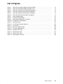
About the FDDI UTP Single Ring Adapter
The FDDI UTP Single Ring (Type B2-P for MCA Adapters and B5-3 for PCI Adapters) are
fitted with an Unshielded Twisted Pair/TP–PMD (MLT 3) connector which offers
cost–effective integration of MicroChannel and PCI Platforms into the fast 100 Mbps FDDI
network.
The boards comply with ANSI TP–PMD Revision 2.1 (MTL–3). Its RJ–45 connector
provides for attachment of 100 ohm UTP category 5 cables.
8-Position Connector RJ-45
For Unshielded Twisted–Pair
(UTP) Cabling – Port S
LED (green)
Internal 60-Position
Card Edge Connector
LED (yellow)
Figure 1. FDDI UTP Single Ring Adapter (Type B2-P MCA).
8-Position Connector RJ-45
For Unshielded Twisted–Pair
(UTP) Cabling – Port S
LED (green)
LED (yellow)
Figure 2. FDDI UTP Single Ring Adapter (Type B5-3 PCI).
1-2
FDDI Adapters – Installation and Configuration Guide
UTP Single Ring Adapter Characteristics
The main characteristics are:
• Data Streaming support
• Low cost RJ–45 connector
• MLT–3 interoperability
• Up to 100 m between nodes
• Fully software configurable
• SMT 7.3
• Suitable for multimedia applications (support of synchronous mode – see Appendix A).
Environment Requirements and Compliance
Electrical power source loading
+5V DC @ 2A
+12v DC @ 50mA.
Environment
Operating (Ambient) temperature:
+10 to 40 _C
Storage temperature:
–20 to 60 _C
Operating humidity:
30% to 80% (non–condensing)
Storage humidity:
10% to 90% (non–condensing)
Introducing FDDI Adapters
1-3
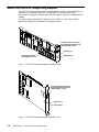
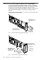
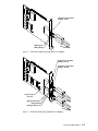
About the FDDI Fiber Single Ring and Dual Ring Adapters
The FDDI Fiber Single Ring (Type B2-R for MCA Adapter), see Figure 3, and the FDDI
Fiber Dual Ring (Type B2-S for MCA Adapter, see Figure 4, use a MIC fiber optic cabling
connection to integrate fiber optic/Micro Channel systems with the 16/32–bit MicroChannel
bus architecture via a FDDI concentrator into 100Mbps FDDI fiber optic network.
The FDDI Fiber Single Ring (Type B5-4 for PCI Adapter), see Figure 5, and the FDDI Fiber
Dual Ring (Type B5-5 for PCI Adapter), see Figure 6, use a SC fiber optic cabling
connection.
The boards comply with ANSI standard X3T9.5. The FDDI Fiber Dual Ring Adapter allows a
station integration in the dual FDDI Ring.
MIC Connector for
Fiber Cabling - Port S
Internal 60-Position
Card Edge Connector
LED (green)
LED (yellow)
Figure 3. FDDI Fiber Single Ring (Type B2-R MCA Adapter).
MIC Connector for
Fiber Cabling - Port B
LED (green)
Single Internal
60-Position Card Edge
Connector
on main board
MIC Connector for
Fiber Cabling - Port A
Optical Bypass
Interface
Figure 4. FDDI Fiber Dual Ring (Type B2-S MCA Adapter).
1-4
FDDI Adapters – Installation and Configuration Guide
LED (yellow)
LED (green)
SC Connector for Fiber
Cabling - Port S
LED (green)
LED (yellow)
Red
Figure 5. FDDI Fiber Single Ring (Type B5-4 PCI Adapter).
SC Connector for Fiber
Cabling - Port A
SC Connector for Fiber
Cabling - Port B
Optical Bypass
Interface
LED (green) Port B
LED (yellow)
Red
LED (green) Port A
Red
Figure 6. FDDI Fiber Dual Ring (Type B5-5 PCI Adapter).
Introducing FDDI Adapters
1-5
Fiber Adapter Characteristics
The main characteristics are:
• Data Streaming support
• MIC connector for MCA, SC connector for PCI
• Up to 2 km between nodes
• Fully software configurable
• SMT 7.3
• Suitable for multimedia applications (support of synchronous mode – see Appendix A).
• Dual Ring Adapter: the Optical Bypass Interface provides the facility of optical isolation
from the FDDI network while maintaining continuity of cabling connections.
Environment Requirements and Compliance
Electrical power source loading
+5V DC @ (2A for Single, 2.65A for Dual Adapters)
+12v DC @ 50mA.
Environment
Operating (Ambient) temperature:
+10 to 40 _C
Storage temperature:
–20 to 60 _C
Operating humidity:
30% to 80% (non–condensing)
Storage humidity:
10% to 90% (non–condensing)
1-6
FDDI Adapters – Installation and Configuration Guide
Chapter 2. Hardware Installation
This section provides instructions for installing FDDI Adapters in MCA and PCI bus
computers.
FDDI Adapters Installation
1. Turn off your computer’s power and remove the cover (refer to your computer’s manual
for instructions on cover removal and option board installation and cautions).
2. Locate an available MCA or PCI slot in your computer and remove the external slot plate
(you will need to loosen the thumbscrew to do this). Two adjacent slots are necessary for
the MCA Fiber Dual Ring Adapter.
3. Plug the adapter into an MCA or PCI slot, making sure that the ”fork” is in the position
under the endplate thumbscrew.
The MCA Fiber Dual Ring Adapter requires two adjacent slots, only one being used for
the single connector.
Tighten the thumbscrew (two, for the MCA Fiber Dual Ring Adapter).
Warning: Connection of an Optical Bypass on the Dual Ring Board requires a reboot of
the machine in order for the board to be detected.
4. Plug the connector into the board’s endplate. Ensure that the locking clip is engaged.
5. Replace your computer’s cover.
6. Reconnect the power cable to the system; then turn on the power.
Warning: FDDI adapters contain static–sensitive components. Always touch a grounded
surface to discharge static electricity before handling the adapter.
Hardware Installation
2-1
2-2
FDDI Adapters – Installation and Configuration Guide
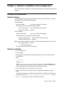
Chapter 3. Software Installation and Configuration
This section provides instructions for installing and configuring the software supporting FDDI
Adapters.
Delivery and Installation
Software Delivery
The FDDI Adapter package is part of the Bull Enhancement CD–ROM delivery. It contains
the following LPP (Licensed Program Product):
For MCA Adapters
necessary to support FDDI Adapter.
devices.mca.0083
which contain two OPPs (Optional Program Product):
devices.mca.0083.rte
driver, methods and specific utilities.
devices.mca.0083.diag
diagnosis.
For PCI Adapters
devices.pci.48110040
necessary to support FDDI Adapter.
which contain two OPPs (Optional Program Product):
devices.pci.48110040.rte
driver, methods and specific utilities.
devices.pci.48110040.diag
diagnosis.
Note: In the event of a problem installing the FDDI Adapter package (MCA or PCI), check
that the following OPP is installed:
devices.mca.8ef4.com
This OPP is part of the AIX CD–ROM delivery.
Software Installation
1. Turn the computer on.
2. Log in as root.
3. Insert the Bull Enhancement CD–ROM containing the device driver software into the
CD–ROM drive.
4. Enter:
smit cfgmgr
and press Enter.
The Install/Configure Devices Added After IPL screen is displayed. The
”INPUT device/directory for software” option is highlighted. The cursor is positioned on
the entry field where you can identify the input device you are using.
5. Press F4 to display a list of input devices you can select.
6. Select the CD–ROM by moving the cursor to the appropriate media type and press
Enter.
The device or directory you selected is now displayed in the ”INPUT device/directory for
software” option on the Install/Configure Devices Added After IPL screen.
7. Press Enter to execute the software installation command.
Software Installation
3-1
The COMMAND STATUS screen is displayed. The status will change from Running to
OK when the software installation is complete.
Note: If an error message is displayed on the COMMAND STATUS screen, verify that the
adapter is seated properly. If the error message is present when the adapter is
securely installed, refer to the documentation that came with your computer for
information on running hardware diagnostics.
8. Remove the installation media from the drive.
9. Press F10 to exit SMIT.
Note: In the case of an FDDI Adapter upgrade, the previous release must first be
de–installed using the command
for MCA
installp –u devices.mca.0083
for PCI
installp –u devices.pci.48110040
before using smit cfgmgr.
Installation Check
You can check the successful installation with the lsdev command, which lists the adapters
installed on the system.
MCA example:
# lsdev –Cc adapter | grep fddi
fddi0 Available 00–07
fddi1 Available 00–06
FDDI Adapter
FDDI Adapter
PCI example:
# lsdev –Cc adapter | grep fddi
fddi0 Available 00–01
PCI FDDI Adapter (48110040)
Fiber Ring Adapter Driver – Operational States
Note: In the following table, the extender (Dual Ring) LED does not apply with a Single
Ring adapter.
Dual
Ring
Single
Ring
Explanation
Green
LED
Green
LED
Yellow
LED
off
off
off
driver not loaded, adapter not operational
off
off
on
station management code is running, adapter is not connected to the network (for example, cable is disconnected).
off
on
off
Single Ring: adapter is ready for use (connected to network
and operational).
Dual ring: base adapter is operational in loopback mode.
on
off
off
Single Ring: driver not loaded, adapter not operational.
Dual Ring: extender adapter is operational in loopback
mode.
on
on
off
adapter is ready for use (connected to network and operational).
See FDDI Fiber Dual Ring (Type B2-S) Adapter, Figure 3, for physical location of LEDs.
3-2
FDDI Adapters – Installation and Configuration Guide
Adapter Configuration
The following procedure allows you to configure an FDDI adapter.
Procedure
1. Enter the SMIT fast path:
# smit fddi
Note: Depending on your environment, you access SMIT in ASCII mode or AIXwindows
mode. The following steps apply to both interfaces.
2. Select Adapter.
The SMIT panel for this selection resembles the following figure.
Adapter
Move cursor to desired item and press Enter.
List All FDDI Adapters
Change / Show Characteristics of an FDDI Adapter
Generate Error Report
Trace an FDDI Adapter
3. Select Change/Show Characteristics of an FDDI Adapter.
Software Installation
3-3
The SMIT panel for this selection resembles the following figure (MCA adapters).
FDDI Adapter
Move cursor to desired item and press Enter.
fddi0 Available 00–07 FDDI Adapter
fddi1 Available 00–06 FDDI Adapter
F1=Help
F2=Refresh
F3=Cancel
Esc+8=Image
Esc+0=Exit
Enter=Do
/=Find
n=Find Next
4. Make a selection from the Available FDDI Adapters. If no adapters are displayed or if
they are in Defined state, check the configuration and setup again.
3-4
FDDI Adapters – Installation and Configuration Guide
When the appropriate FDDI adapter is selected, a SMIT panel resembling the following
figure will be displayed (PCI adapter):
Change/Show Characteristics of an FDDI Adapter
Type or select values in entry fields.
Press Enter AFTER making all desired changes.
[TOP
Logical Name
Description
Status
Location
Transmit Queue Size
PCI Fix value
TVX lower bound
MAX T–REQ
Enable Alternate MAC/SMT Address
Alternate MAC/SMT Address
PMF password
USER Data
SBA_Payload
SBA_Overhead
Max_TNEG
Min_Segm_Size
SBA_Category
Sync_Tx_Mode
SBA_Command
SBA_Available
Extended receive mbuf size
Receive frame count
Apply change to DATABASE only
F1=Help
F5=Reset
F9=Shell
F2=Refresh
F6=Command
F10=Exit
[Entry Fields]
fddi0
PCI FDDI Adap. (4811)
Available
04–01
[30]
+#
[00000000]
+#
[2700]
+#
[165]
+#
no
+
[400000000000]
[]
[]
[0]
+#
[50]
+#
[25]
+#
[1]
+#
[0]
+#
SPLIT
+
STOP
+
[50]
+#
no
+
[42]
+#
no
+
F3=Cancel
F7=Edit
Enter=Do
F4=List
F8=Image
Note: The following fields are no displayed in the MCA adapter SMIT menu:
– PCI Fix value,
– Extended receive mbuf size
– Receive frame count
Software Installation
3-5
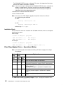
SMIT Field Definitions for FDDI Adapter
The following is a summary of the FDDI attributes and values shown on the SMIT Change /
Show Characteristics menu of an FDDI Adapter.
Note: Most of these attributes are advanced parameters which give access to FDDI SMT
or configure the synchronous mode. It is recommended that only advanced users
change the default values of parameters listed here.
SMT Parameters:
TVX lower bound
Max T–Req
PMF password
User Data.
Synchronous Mode Parameters:
SBA Payload
SBA Overhead
Max_TNEG
Min_Segm_Size
SBA_Category
Sync_Tx_Mode
SBA_Command
SBA_Available.
Description
Provides a short text description of the adapter. The value of this field
cannot be changed.
Status
Indicates the current status of the adapter. Possible values are available,
indicating that the adapter is configured in the system and ready to use,
and defined, indicating that the adapter is defined to the system but not
configured.
Location
The location code for an adapter consists of two pairs of digits with the
format AA–BB, where AA identifies the location code of the drawer
containing the adapter and BB identifies both the I/O bus and slot
containing the adapter.
A value of 00 for the AA field means that the adapter is located in the CPU
drawer or system unit, depending on the type of system. Any other value for
the AA field indicates that the adapter is located in an I/O expansion
drawer, in which case, the value identifies the I/O bus and slot number in
the CPU drawer that contains the asynchronous expansion adapter. The
first digit identifies the I/O bus with 0 corresponding to the standard I/O bus
and 1 corresponding to the optional I/O bus. The second digit identifies the
slot on the indicated I/O bus.
The first digit of the BB field identifies the I/O bus containing the adapter. If
the adapter is in the CPU drawer or system unit, this digit will be 0 for the
standard I/O bus or 1 for the optional I/O bus. If the adapter is in an I/O
expansion drawer, this digit is 0. The second digit identifies the slot number
on the indicated I/O bus (or slot number in the I/O expansion drawer) which
contains the adapter.
A location code of 00–00 is used to identify the standard I/O planar.
Examples:
00–05
Identifies an adapter in slot 5 of the standard I/O bus and is located in either
the CPU drawer or system unit, depending on the type of system.
00–12
Identifies an adapter in slot 2 of the optional I/O bus and is located in the
CPU drawer.
3-6
FDDI Adapters – Installation and Configuration Guide
18–05
Identifies an adapter located in slot 5 of an I/O expansion drawer. The
drawer is the one connected to the asynchronous expansion adapter
located in slot 8 of the optional I/O bus in the CPU drawer.
Transmit Queue Size
Transmit Queue size: indicates the number of transmit requests (frames)
that can be queued up by the device driver prior to being added to the
adapters (hardware) transmit queue.
Valid values range from 3 to 250. The default value is 30.
PCI Fix Value
Not used.
TVX lower bound
Provides local write access to the TVX attribute, registered as fddiMAC 54
in the SMT Standard.
The attribute provides local control of the recovery time from transient ring
errors. The value for TVX Lower Bound is specified in microseconds. The
value range is 2500 µs ... 10000 µs. If a value outside the limits is specified,
the upper/lower limit will be taken. If no value is specified, the default value
2700 µs is used.
MAX T–Req
Provides local write access to the T–Req attribute, registered as fddiMAC
51 in the SMT Standard. T–REQ specifies the requested target rotation
time (TTRT) for this station and directly affects ring utilization. The value for
TReq is specified in milliseconds. The value range is 5 ms ... 165 ms. If a
value outside the limits is specified, the upper/lower limit will be taken. If no
value is specified, the default value 10 ms is used.
Enable Alternate MAC/SMT Address
Setting this attribute to the yes value indicates that the address of the
adapter, as it appears on the LAN is the one specified by the Alternate
MAC/SMT Address attribute. If you specify the no value, the unique adapter
address written in a ROM on the adapter is used. The default value is no.
Alternate MAC/SMT Address
Allows the adapter unique address, as it appears on the LAN, to be
changed. The value entered must be a FDDI address in canonical form of
12 hexadecimal digits (6 bytes) and have the group address bit set to 0 and
the local address bit set to 1. The group address bit is the high order bit of
the high order byte; the local address bit is the second highest order bit of
the high order byte. The address must not be the same as any other FDDI
address on the ring. This field has no effect unless the Enable Alternate
MAC/SMT Address attribute is set to the yes value, in which case this field
must be filled in. To change the Alternate MAC/SMT Address, enter 0x
followed by the 12 digit address. All 12 hexadecimal digits must be entered.
The valid values range from 0x400000000000 through 0x7fffffffffff. The
default value is 0x400000000000.
PMF password If this attribute has a non-zero value, it defines the password that all remote
PMF (Parameter Management Frame) requests must provide to change
attributes within the adapter. The value for pmf_passwd is 8 ASCII
characters long and not case sensitive since lower case letters will be
converted to upper cases. Password protection can be disabled by setting
this attribute to all zeros (default), or by not specifying a PMF Password.
USER Data
This attribute provides local write access to the User Data parameter in the
SMT MIB, registered as fddiSMT 17 in the SMT Standard. The User Data
must be an ASCII string for compliance with the FDDI SMT Standard. It can
be 32 bytes long and can contain any user data; for example station name,
location, etc.
Software Installation
3-7
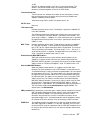
SBA_Payload This attribute defines the requested synchronous bandwidth for manual
static allocations in synchronous units (SU). The synchronous unit is the
number of bytes transmitted in 125 microseconds. Value range: 0 ... 1562
bytes per 125 microseconds. (1562 SU = 100 Mbits/sec). The correlation
between a payload given in Mbits/sec and in Synchronous Units, as
specified in the SMT ANSI Standard, is shown in the following table.
Mbits/
sec
1
Payload 16
2
3
4
5
10
15
20
25
30
35
40
45
50
32
47
63
79
157
235
313
391
469
547
625
704
782
The default value is zero – no synchronous bandwidth is used.
If a value outside the valid range is specified, the upper or lower limit will be
taken.
You must define the amount of bandwidth in order to send synchronous
frames. If the SbaPayLoad keyword is not specified, the SbaOverHead,
MaxTNeg, MinSegmentSize and SbaCategory keywords have no effects.
The workstation supports either the static allocation mode (where the
requested payload is specified by the SbaPayLoad keyword), or the
dynamic allocation mode (where the required synchronous bandwidth is
allocated directly by the multimedia application).
If you use a multimedia application which can allocate the bandwidth
dynamically, do not specify a value for the SbaPayLoad keyword.
Conversion Formula
[Requested Payload (bytes/sec)] x 125E–6 = SbaPayLoad (SU)
Example:
if the required bandwidth is 1 MBit/sec (125,000 Bytes/sec), the value of the
payload is
125,000 x 125E–6 = 15.625 (rounded up to 16 SU).
SBA_Overhead
This attribute defines the requested overhead for static allocations. The
value range is 50 ... 5000 bytes. If a value outside the limits is specified, the
upper/lower limit will be taken. The default value is 50 bytes.
Note: This attribute only has effect if the attribute SBA_Payload has a value
greater than 0.
Max_TNEG
This attribute defines the maximum token rotation delay which can be
accepted by applications using synchronous bandwidth. The value range is
5 ... 165 ms. The default value is 25 ms. If a value outside the limits is
specified, the upper/lower limit will be taken.
Note: This attribute only has an effect if the attribute SBA_Payload has a
value greater than 0.
CAUTION: If a value lower than 20 ms is specified for the Max_TNEG
attribute, the Max T–Req attribute should be set to the same value (Max
T–Req = MaxTNeg). The synchronous payload request will be denied by
the SBA if the value for the MaxTNeg attribute is lower than the current
token rotation time.
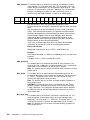
Min_Segm_Size
This attribute defines the minimum synchronous segmentation size. This
value corresponds to the amount of bytes to be transmitted per token
opportunity. The value range is 1 ... 4478 bytes. The default value is 1. If a
value outside the limits is specified, the upper/lower limit will be taken.
Note: This attribute only has an effect if the attribute SBA_Payload has a
value greater than 0.
3-8
FDDI Adapters – Installation and Configuration Guide
SBA_Category This attribute defines the session ID of the SBA_Category for the static
allocation. The value range is 0 ...65535. The default value is 0. If a value
outside the limits is specified, the upper/lower limit will be taken.
Note: This attribute only has an effect if the attribute SBA_Payload has a
value greater than 0
Sync_Tx_Mode
This attribute defines the synchronous transmission mode. The default
value is ’SPLIT’, where only frames identified as synchronous frames are
transmitted by the synchronous queue. The alternative value is ’ALL’, where
all LLC frames received from upper layers are transmitted via the
synchronous queue.
Note: This attribute only has an effect if the ESS is able to allocate the
required synchronous bandwidth from the SBA.
SBA_Command
This attribute is an SBA local action to start or stop the SBA application.
Values may be ’START’ or ’STOP’. The default value is ’STOP’.
Note: There should be only one active SBA application in the same
segment.
SBA_Available
This attribute defines the maximum synchronous bandwidth in percent
available for the primary path. The value range is 0...100 percent. The
default value is 50 percent (6.25 MBytes/s). If a value outside the limits is
specified, the upper/lower limit will be taken.
Note: This value remains zero until the SBA application is enabled and
active.
Extended receive mbuf size
Extended receive mbuf size: this parameter defines the type of mbuf
allocation.If you specify ‘yes‘ the receive mbufs will be allocated with a
single cluster of more than 4 Kbyte size. Since the driver must preallocate a
number of receive buffers typically 8 Kbyte mbufs will be allocated for each
receive buffer. This can increase performance but will also consume mbufs
of the contiguos memory pool. Due to the limited number of large mbufs the
system may run out of mbufs. If you specify ‘no‘ default allocation will be
used. his means that receive frames are allocated as a chain of two 4 Kyte
mbufs. This can decrease the receive performance but avoids that the
system runs out of resources.
Please see also the ’Receive frame count’ parameter.”
Receive frame count
This parameter defines the number of receive buffers that will be allocated
by the driver for receive operation. When the driver is initialized it will
preallocate up to the given number of receive buffers. Also it will refill the
receive buffer ring during receive operation. Depending on the receive mbuf
size you can decrease or increase the amount of memory that is held in the
driver‘s receive queue.
Please see also the ‘Extended receive mbuf size‘ parameter.”
Apply change to DATABASE only
Indicates whether or not the configuration changes being made should be
applied only to the database or to both the database and the current device
operation. For devices that are in use and cannot be changed this allows
the database to be changed for the device so that the changes take effect
the next time the system is rebooted. Possible values: ’yes’ or ’no’,
Software Installation
3-9
3-10
FDDI Adapters – Installation and Configuration Guide
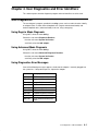
Chapter 4. User Diagnostics and Error Identifiers
This section explains how the diagnostic program and error identifiers are to be used.
User Diagnostics
The user diagnosis program, provided in the diag system, can be used to check or identify
an adapter failure. It allows internal loopback tests (regular and advanced mode) and
external loopback tests (advanced mode) to be run, using a wrap plug.
Using Regular Mode Diagnosis
Using SMIT, select the menu # diag
Choose the sub–menu Diagnostic Routines
then the sub–menu System Verification
and finally select the fddi adapter.
Using Advanced Mode Diagnosis
Using SMIT, select the menu # diag
Choose the sub–menu Advanced Diagnostic Routines
then the sub–menu System Verification
and finally select the fddi adapter.
Using Diagnostics Error Messages
If one of the following messages appears, check that the adapter is correctly plugged into
the system bus. If the problem persists, replace the adapter.
859–201
Config register test failure
859–202
PROM check test failure
859–203
Timer and IRQ test failure
859–204
Adapter RAM check failure
859–205
ASIC test failure
859–206
High memory (ISA) test failure
859–207
DMA test failure
859–208
FORMAC register test failure
859–209
PLC1 (base board) test failure
859–210
PLC2 (extension board) test
failure
User Diagnostics & Error Identifiers
4-1
If one of the following messages appears, check that the wrap plugs (if any) are correctly
plugged. If problem persists, replace the adapter.
859–301
PLC1 (base board) FDDI
external wrap failure
859–302
PLC2 (extension board) FDDI
external wrap failure
If the following message appears, check the software installation.
859–400
Software
Traces
Start Traces
To start the traces, use either,
the trace command:
# trace –j 45d –a
or, the SMIT interface.
Using SMIT, select the menu # smit trace
Choose the sub–menu Start Trace
and finally select the Additional event IDs to trace
and give the hook id.
The trace hook identifier for the FDDI Adapter is 0x45d for reception and transmission,
0x45e for ioctl trace and 0x45f for error trace.
Stop Traces
To stop the traces, use either,
the trcstop command:
#trcstop
or, the SMIT interface.
Using SMIT, select the menu # smit trace
Choose the sub–menu Stop Trace.
How to Generate a Trace Report
To generate a trace report, use either,
the trcrpt command:
#trcrpt
or, the SMIT interface.
Using SMIT, select the menu # smit trace
Choose the sub–menu Generate a Trace Report
the screens allow the report to be customized.
4-2
FDDI Adapters – Installation and Configuration Guide
Appendix A. Synchronous & Asynchronous Services
Types of Service
The FDDI standard defines two types of service: synchronous and asynchronous.
Asynchronous Service
The basic service provided by an FDDI adapter. It does not guarantee end–to–end delay
and reserved bandwidth.
Synchronous Service
Used by applications requesting and requiring predictable response time.
A part of the available bandwidth of the FDDI ring capacity can be allocated for synchronous
transmission. The corresponding traffic is given priority over asynchronous traffic, allowing
workstations to have guaranteed access to the network through a process called
Bandwidth Allocation Process.
Bandwidth Allocation is the process that controls the overall bandwidth allocation for one
FDDI segment, as well as the recovery process due to potential over–allocation and to
token rotation timer change. Two allocation modes presently exist: Static mode and
Dynamic mode.
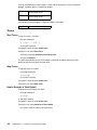
Static Mode
Mode where only one allocation is performed per workstation. This allocation takes into
account all bandwidth requirements for the workstation. The Static Allocation mode is shown
in Figure 7.
Server ESS
(End–Station Support)
SBA
(Synchronous
Bandwidth Allocator)
Client
Server requests bandwidth
SBA grants allocation
for workstation
SBA
Server ESS
Client request
Client
Server starts
synch. traffic
Figure 7. Static Allocation Mode.
Appendix A – Synchronous & Asynchronous Services
A-1
Dynamic Mode
Mode where allocation is performed for each individual session (where a session is the
requirement of a single application on a workstation). In this mode, several allocations can
be performed on each workstation. The Dynamic Allocation mode is shown in Figure 8.
Server ESS
(End–Station Support)
SBA
(Synchronous
Bandwidth Allocator)
Client
Client requests
a new session
Server requests bandwidth
for this session
SBA
Server ESS
Client
Allocation granted
Server can
start session
Figure 8. Dynamic Allocation Mode.
FDDI Synchronous Transmission
Two functions are provided to support synchronous transmission: Synchronous
End–Station Support (ESS) and Synchronous Bandwidth Allocator (SBA).
End–Station Support refers to an FDDI workstation’s ability to prioritize synchronous traffic
over regular asynchronous traffic. Since this prioritization is done only while transmitting,
ESS is used mainly by workstations requiring guaranteed access to the network.
Figures 7 and 8 show that prioritization is gated by the acceptance or refusal of the
bandwidth allocation request sent to the SBA. This request is made upon ESS workstation
boot time in static mode or before starting every new session in dynamic mode.
If SBA refuses an ESS allocation request, the ESS will use the asynchronous queue instead
of using the synchronous queue to transmit its data. If this happens, the quality of service of
the corresponding traffic is not guaranteed.
A-2
FDDI Adapters – Installation and Configuration Guide
SBA / ESS Parameters
Overview
This section contains information about the adapter parameters which must be modified to
configure the synchronous services. The parameters configure the operation of ESS and
SBA functions. These functions are part of the device driver and are installed with it.
Note: If static mode is used and this workstation is configured to use synchronous
transmission, the default value must be changed for the
– SbaCommand,
– SbaPayLoad.
Default values of the other parameters can also be changed. Only advanced users are
recommended to do so. Otherwise, a system failure may result.
The two following tables give a summary of parameters required to configure SBA and ESS
in Static mode and in Dynamic mode; they also list default values.
Static Mode
ESS
SBA
Name
Default Value
Name
Default Value
SbaCommand
STOP
SbaPayLoad
0
(User MUST change it to
get bandwidth)
SbaAvailable
50
Not Applicable if
SbaCommand =
STOP
SbaOverHead
50
Not Applicable (N/A) if
SbaPayLoad = 0
MaxTNeg
25
N/A if SbaPayLoad = 0
MinSegmentSize 1
N/A if SbaPayLoad = 0
SbaCategory
0
N/A if SbaPayLoad = 0
SynchTxMode
SPLIT
N/A if SbaPayLoad = 0
Dynamic Mode
ESS
SBA
Name
Default Value
Name
Default Value
SbaCommand
STOP
SbaPayLoad
SbaPayLoad MUST be 0
SbaAvailable
50
Not Applicable if
SbaCommand =
STOP
SbaOverHead
MaxTNeg
Application will request
all needed parameters
from network Allocator
MinSegmentSize
SbaCategory
SynchTxMode
SPLIT
Appendix A – Synchronous & Asynchronous Services
A-3
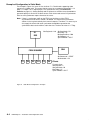
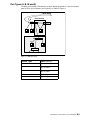
Example of Configuration in Static Mode
For example in Figure 9, a server S1 has 6 clients C1...C6 with cards supporting video
streams of 1.2 Mbps each. This means that the server has to support a payload of 6 x 1.2
Mbps = 7.2 Mbps. This is equivalent to 112.5 Synchronous Units (see Conversion
Formula, on page 3-8). Setting SbaPayLoad to 120 ensures sufficient server bandwidth to
guarantee quality of service for all video streams. Each client needs overall 2 Synchronous
Units to send synchronous request frames to the server.
Note: If there is synchronous traffic on the FDDI ring, the fairness of the FDDI’s
asynchronous media access control is disturbed. This means the asynchronous
stations in the ring have to delay their transmit requests. Therefore, it is necessary to
also supply the clients with some synchronous bandwidth to guarantee the
synchronous data transfer within a stable time slot. The time slot value is 2 * TNeg.
SbaPayLoad = 120
S1
ESS
SbaOverHead = 50
MaxTNeg = 25
MinSegmentSize = 500
SbaCategory = 0
SynchTxMode = SPLIT
SBA
FDDI SEGMENT
SbaCommand = START
SbaAvailable = 50
C1
C2
C3
C4
C5
C6
Clients
For each client:
SbaPayLoad = 2
SbaOverHead = 50
MaxTNeg = 25
SynchTxMode = SPLIT
Figure 9. Static Mode Configuration – Example.
A-4
FDDI Adapters – Installation and Configuration Guide
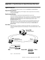
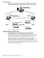
Appendix B. Connections to Your Network
Connections Overview
The SAS adapter supports single attachment to a concentrator.
The DAS adapter supports either dual attachment to the main ring path or dual homing to
one or two FDDI concentrators.
A typical example of an FDDI network organization is shown in Figure 10.
FDDI–Ring
Dual Attachment
Computer with
DAS Adapter Installed
Dual Homing
DAC Concentrator
Computer with
SAS Adapter Installed
Standard
SAC Concentrator
Stand Alone
Cascading
Note: The transceiver type of concentrator slot(s) must fit the transceiver type of the
FDDI adapter(s) that are used (fiber optical or MLT-3).
Figure 10. Example of an FDDI Network.
Appendix B – Connections to Your Network
B-1
Connection Types
There are three basic connection types that can be mixed and matched in the same
network:
• Dual attachment to the dual ring
• Single attachment to a concentrator
• Dual homing.
Dual Attachment to the Dual Ring
Class A devices can be connected directly to the FDDI dual ring. A device connected to
both rings is called ”dual attached”. Since each ring has a transmit and receive line, there
are two transmit paths out of and two receive paths into the dual attached device (DAS or
DAC in Figure 10). Because of redundant data paths, dual attachment offers fault tolerance.
Single Attachment to a Concentrator
Class B devices connect point to point to a concentrator. This connection type is called
”single attached”. For single attached devices, the concentrator acts as the central hub.
When SASs are connected to a single concentrator, the concentrator is said to be
non–attach or stand alone. In this situation, the dual ring is collapsed into the concentrator.
Both SASs and SACs can be single attached.
Dual Homing
This is a connection type for a Class A device where it connects to two different
concentrators. The connection to one concentrator is the primary connect and is active; the
connection to the other concentrator is for backup purposes and inactive. Since each
connection to the concentrator has a send and a receive path, there are two transmit paths
out of and two receive paths into the dual home device. Because of redundant data paths,
dual attachment offers fault tolerance.
Both DASs and DACs can be dual homed.
When concentrators are connected to other concentrators building a tree below the dual
ring, it is called ”cascading”. Cascading applies to both single attached and dual homed
concentrators off the dual ring.
B-2
FDDI Adapters – Installation and Configuration Guide
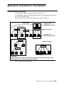
Port Types (A, B, M and S)
The ports on the various FDDI devices are given logical designations. There are four port
types in FDDI: A, B, M (Master) and S (Slave), as shown in Figure 11.
FDDI–Ring
Dual Homing
A
B
M
M
S
S S
M
M
S
S
Figure 11. FDDI Port Types.
Device Type
Ports (quantity)
DAS
A & B (1 each)
DAC
A & B (1 each)
M (1 or more)
SAC
S (1)
M (1 or more)
SAS
S (1)
Stand Alone Concentrator
M (multiple)
Appendix B – Connections to Your Network
B-3
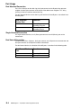
Port Usage
Dual Attached Connection
For a Class A device on the dual ring, the A port connects to the B port of the upstream
neighbor and the B port connects to the A port of the downstream neighbor. This ”daisy
chaining” of devices continues around the ring.
For dual attached devices on the dual ring, the function of A and B ports is described in the
following table.
Dual Attached
Device Port
Function
A
Primary Ring In
Secondary Ring Out
B
Primary Ring Out
Secondary Ring In
Single Attached Connection
On single attached devices, the S (Slave) port connects to an M (Master) port on the
concentrator.
Dual Homed Connection
For dual homed Class A devices, the A port connects to an M port on one concentrator and
the B port connects to an M port on another concentrator.
For dual homed devices, the function of A and B ports is described in the following table.
B-4
Dual Homed Device
Port
Function
A
Secondary Connection
B
Primary Connection
FDDI Adapters – Installation and Configuration Guide
Type of Connectors
Two types of connectors are used for FDDI Adapters:
• UTP (copper) connector
• Fiber ring connectors.
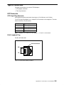
UTP Connector
UTP Single Ring Connector
Unshielded twisted pair port pinouts for port types A, B, M (Master) and S (Slave).
The UTP Single Ring Adapter uses standard RJ-45 connectors and receptacles. The table
below summarizes the port pinouts.
RJ-45 Contact
Signal
1
Transmit (Tx+)
2
Transmit (Tx–)
7
Receive (Rx+)
8
Receive (Rx–)
Note: Category 5 UTP cables for FDDI require 1 $ 7 and 2 $ 8 crossovers.
RJ-45 Loopback Plug
Part No. 90713001–001
RJ-45 Connector
RX–
TX–
RX+
TX+
Figure 12. RJ-45 Pinout Showing Loopback.
Appendix B – Connections to Your Network
B-5
RJ-45 Cable
M.I. CBLG159–1900
Part No. 90720001–001
Figure 13. RJ-45 Cable.
Fiber Ring Connectors
MIC Fiber Loopback Plug (MCA adapters)
Part No. 92F9003
MIC Connector
Figure 14. MIC Fiber Loopback Plug.
SC Fiber Loopback Plug (PCI adapters)
Part No. 16G5609
Figure 15. SC Fiber Loopback Plug.
B-6
FDDI Adapters – Installation and Configuration Guide
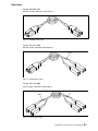
Fiber Cable
Part No. CBLR065-210E
MIC/MIC Length 7.00 meters (Bull Express).
Figure 16. MIC/MIC Fiber Cable.
Part No. CBLG171-2000
MIC/SC Length 7.00 meters (Bull Express).
Red
Figure 17. MIC/SC Fiber Cable.
Part No. CBLG170-2000
SC/SC Length 7.00 meters (Bull Express).
Red
Red
Figure 18. SC/SC Fiber Cable.
Appendix B – Connections to Your Network
B-7
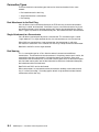
Optical Bypass Interface
Pin 6:
Switch present
Pin 4: Switch
primary ring
Pin 2: Vcc
See also FDDI Adapters Installation, Step 3 Note, on page 2-1.
Figure 19. Optical Bypass Interface.
B-8
FDDI Adapters – Installation and Configuration Guide
Pin 5:
Ground
Pin 3: Switch
secondary ring
Pin 1: Vcc
Glossary
This glossary contains abbreviations, key–words and phrases that can be found in this document.
AC
Alternating Current
MIC
Media Interface Connector
ANSI
American National Standards Institute
PCI
Peripheral Component Interconnect
DAC
Dual Attachment Concentrator
PMF
Parameter Management Frame
DAS
Dual Attachment Station
SAC
Stand Alone Concentrator
ESS
End Station Support
SAS
Single Attachment Station
FDDI
Fiber Distributed Data Interface
SBA
Synchronous Bandwidth Allocator
IPL
Initial Program Load
SMT
Station Management
LLC
Logical Link Control
SU
Synchronous Units
MAC
Media Access Control
TTRT
Target Rotation Time
MCA
Micro Channel Architecture
UTP
Unshielded Twisted Pair
MIB
Management Information Base
Glossary
G-1
G-2
FDDI Adapters – Installation and Configuration Guide
Vos remarques sur ce document / Technical publication remark form
Titre / Title :
Bull DPX/20 FDDI Adapters Installation and Configuration Guide
Nº Reférence / Reference Nº :
86 A1 53GX 01
Daté / Dated :
September 1996
ERREURS DETECTEES / ERRORS IN PUBLICATION
AMELIORATIONS SUGGEREES / SUGGESTIONS FOR IMPROVEMENT TO PUBLICATION
Vos remarques et suggestions seront examinées attentivement
Si vous désirez une réponse écrite, veuillez indiquer ci-après votre adresse postale complète.
Your comments will be promptly investigated by qualified technical personnel and action will be taken as required.
If you require a written reply, please furnish your complete mailing address below.
NOM / NAME :
SOCIETE / COMPANY :
ADRESSE / ADDRESS :
Remettez cet imprimé à un responsable BULL ou envoyez-le directement à :
Please give this technical publication remark form to your BULL representative or mail to:
Bull Electronics Angers S.A.
CEDOC
Atelier de Reprographie
331 Avenue Patton
49 004 ANGERS CEDEX 01
FRANCE
Date :
ORDER REFERENCE
86 A1 53GX 01
PLACE BAR CODE IN LOWER
LEFT CORNER
Bull Electronics Angers S.A.
CEDOC
Atelier de Reprographie
331 Avenue Patton
49 004 ANGERS CEDEX 01
FRANCE
Utiliser les marques de découpe pour obtenir les étiquettes.
Use the cut marks to get the labels.
DPX/20
FDDI Adapters
Installation and
Configuration
Guide
86 A1 53GX 01
DPX/20
FDDI Adapters
Installation and
Configuration
Guide
86 A1 53GX 01
DPX/20
FDDI Adapters
Installation and
Configuration
Guide
86 A1 53GX 01