1
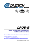
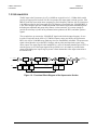
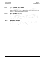
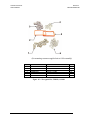
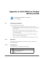
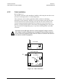
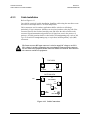
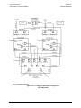
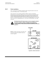
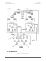
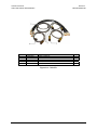
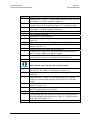
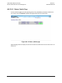
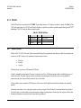
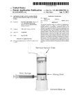
C-Band Transceiver
Introduction
Revision 1
MN/CSAT5060.IOM
1.3.2 UPCONVERTER
The RF input to the Upconverter is at 70 ± 18 MHz at a typical level of -35 dBm which would
provide an output power back-off of 8 dB. In operation, the input signal is mixed up to the 1250
MHz IF in the first conversion mixer operating at a fixed frequency with low side LO injection at
1180 MHz provided by the Upconverter IFLO. IF filtering is provided by the 1250 MHz BPF. It
is just wide enough to pass the 36 MHz bandwidth of the desired signal while maintaining more
than adequate amplitude and group delay flatness. At the same time, it is narrow enough to
provide the necessary rejection to any unwanted mixer products, the IFLO, and other spurious
signals.
The second mixer up converts the 1250 MHz IF signal to the desired output frequency. It uses
low side LO injection in the 4595 to 5175 MHz frequency range provided by the Upconverter
RFLO in 1.000 or 2.500 MHz steps. Both step sizes are automatically selectable. The upconverter
signal is then filtered to reject the RFLO leakage, and any other unwanted mixer spurs at the
mixer output. The output signal is then amplified by a series of internally matched power FET's to
raise the power level of the output signal to the specified level. An isolator is provided at the
output of the high power output stage to protect it from mismatches at the output connection to
the antenna feed.
SSPA
70 +/ - 1 8 M Hz
VA R
ATTEN
VA R
ATTEN
25 WA TTS
6 4 25 - 6 7 25 M Hz
12 5 0 M Hz BPF
COM
M & C
10 M Hz
REFERENCE
IFLO
1 18 0 M Hz
RFLO
51 7 5 54 7 5 M Hz
1 18 0 M Hz
PO WER
SUP PLY
Figure 1-2. Functional Block Diagram of the Upconverter Section
1-5


![Installation Manual [PDF 3.2 MB]](http://vs1.manualzilla.com/store/data/006030502_1-1df8339044a93376c13535e606991dae-150x150.png)