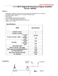
1
HDMI® EXTENDER
O V E R S I N G L E COAX I A L C A B L E
PRODUCT MANUAL
Vanco Part Number
VPW-280577
www.vanco1.com • 888.769.4156
DEAR CUSTOMER
Thank you for purchasing this product.
For optimum performance and safety, please
read these instructions carefully before
connecting, operating or adjusting this product.
Please keep this manual for future reference.
This product is 100% inspected and tested in the United States
to verify HDMI performance parameters.
WARNING
1. Do not expose this unit to water, moisture,
or excessive humidity.
2. Do not install or place this unit in a built-in
cabinet, or other confined space without
adequate ventilation.
3. To prevent risk of electrical shock or fire
hazard, due to overheating, do not obstruct
unit’s ventilation openings.
4. Do not install near any source of heat,
including other units that may produce heat.
6. Only clean unit with a dry cloth.
7. Unplug unit during lightening storms, or
when not used for an extended period
of time. A surge protector is strongly
recommended.
8. Protect the power cord from being walked
on or pinched, particularly at the plugs.
9. Use unit only with accessories specified by
the manufacturer.
10.Refer all servicing to qualified personnel.
5. Do not place unit near flames.
CAUTION
HDMI is a very complex technology requiring continuous authentication of the signal and the same
video resolution and audio settings on all electronic equipment in the system. When there are multiple
sources and displays, the video resolution and audio setting on all connected units must be adjusted
to correspond with that of the display having the lowest video and audio capability.
Note: For best connection and picture quality, use of Generation II BNC Compression Connectors is
strongly recommended. Do not use Type-F to BNC adaptors.
2
www.vanco1.com
FEATURES
The Vanco 280557 HDMI Coaxial Extender uses coaxial cable as the transmission media. Benefits of using the
Vanco 280557 HDMI Coaxial Extender are:
1. The length of HDMI cable is normally offered in fixed length increments and cannot be changed after it
is produced. This is because the HDMI connector can only be effectively soldered and terminated using
tooling, fixtures and eye pattern testing equipment normally only available in a factory. However, coaxial
cables are available in most homes and in many business offices, retail stores, schools, hospitals and
hotels. Most low voltage installers are familiar with coaxial cables and connectors and have the stripping,
crimping, and punch down tools needed for connector termination.
2. The maximum transmission distance for 1080p resolution over good quality RG-59 coaxial cable is 50
meters (164 ft) and over good quality RG-6 is 100 meters (328 ft). To achieve these distances, good
quality compression type BNC connectors must be used. Type F to BNC adapters should not be used,
since they can degrade the quality of the HDMI signal.
3. The transmitter and receiver combination has the ability of buffering and amplifying the HDMI signal.
4. The IR control system is built into the transmitter and the receiver can control the sources from the
displays, or control the displays from the sources.
HDMI® over Single Coaxial Cable Extender
Part # 280577
• Allows HDMI Audio/Video Signals to be
Transmitted Using a single Coaxial Cable
• Transmission Range: Extends 1080p Resolution
Up to 328 ft (100 m) over RG-6 Coaxial Cable
(Dual and Quad-Shielded);Extends 1080p
Resolution Up to 164 ft (50 m) over RG-59
Coaxial Cable
• Works with HDMI and HDCP Compliant Devices
• Supports High Definition Resolution 1080p
• Auto-adjustment of feedback, equalization and
• LED indicators for power and signal status
• Transfers bi-directional IR control signals.
Includes an IR Receiver and IR Emitter.
• Equipped with ESD (Electro-Static Discharge)
protection
• Mounting ears are supplied
• Power Supply: (2) 5V DC
• Dimensions: 5” W x 1” H x 5” D
amplification
888.769.4156
3
SPECIFICATIONS
Operating Temperature Range...................................... -5 to +35°C (+23 to +95 °F)
Operating Humidity Range........................................... 5 to 90 % RH (no condensation)
Input Video Signal....................................................... 0.5-1.0 volts p-p
Input DDC Signal......................................................... 5 volts p-p (TTL)
Video Format Supported.............................................. DTV/HDTV; 1080p/1080i/720p/576i/480i
Output Video.............................................................. HDMI 1.3+HDCP(repeats the source to the display
Output Audio.............................................................. Support 7.1/5.1/stereo audio (PCM only)
Maximum Transmission Distance.................................. 50 to 100 meters (164 to 328 ft)
Power Supply............................................................. 5 VDC
Power Consumption.................................................... 5 Watts (Transmitter) 5 Watts (Receiver)
Dimensions................................................................ 5’’ W × 1’’ H × 5’’ D
Weight .................................................................... 0.9Kg / 1.98lb (Pair)
PACKAGE CONTENTS
Before attempting to use this unit, please check the packaging and make sure the following items are
contained in the shipping carton:
• • • • • 4
One Transmitter Unit
One Receiver Unit
1 IR TX and 1 IR RX
(2) 5 volt, 2 amp power supplies for transmitter and receiver
Product Manual
www.vanco1.com
CONNECT AND OPERATE
Coax Cable
1. Connect the HDMI input source ( such as HD-DVD, PS3, STB, etc.) to the Transmitter unit.
2. Connect a CATV coaxial cable from COAX output of the Transmitter to the COAX input of the Receiver.
3. Connect the HDTV display ( such as HD-LCD,HD-DLP) to the HDMI output of the Receiver.
4. Connect the IR TX pigtail into Transmitter unit; connect the IR RX pigtail into the Receiver unit.
5. Or for reverse operation, connect the IR RX pigtail into the Transmitter unit; connect the IR TX pigtail into
Receiver unit.
Attention: Please insert and extract cables gently.
888.769.4156
5
CONNECT AND OPERATE CONTINUED
DIP switch setting instruction:
Transmitter
Position1Function
0
Range scaling disable.
1
Range scaling enable.
Position2Position3Function
0
0
1080P stereo (Using Embedded EDID) (note1)
0
1
1080P 5.1 (Using Embedded EDID) (note2)
1
0
1080P 7.1 (Using Embedded EDID) (note3)
1
1
EDID auto copy (note4)
Note1: The OP5 will use the embedded 1080p stereo EDID when the DIP switch is in this mode. The EDID will
be 1080p video and stereo audio.
Note2: The OP5 will use the embedded 1080p 5.1 EDID when the DIP switch is in this mode. The EDID will be
1080p video and 5.1 audio.
Note3: The OP5 will use the embedded 1080p 7.1 EDID when the DIP switch is in this mode. The EDID will be
1080p video and 7.1 audio.
Note4: Auto-copy the EDID data to the input port. The Transmitter unit will copy the EDID data from the
display which connected to the Receiver unit.
Receiver
Position1Position2Position3Function
0
0
0
Normal mode, 8 bit color depth
0
0
1
LC mode(note1), 8 bit color depth
0
1
0
Normal mode, color depth decided by the display
0
1
1
LC mode (note1), color depth decided by the display
others
Normal mode,8 bit color depth
Note1: If video appears to have noise or interference when a long coaxial cable is used or the quality of coaxial
cable is not very good, then use this mode.
6
www.vanco1.com
PANEL DISCRIPTIONS TRANSMITTER
888.769.4156
7
PANEL DISCRIPTIONS RECEIVER
8
www.vanco1.com
TROUBLE-SHOOTING
1. Best results are usually achieved when the source and display resolutions are the same. If resolutions
differ, the extenders will try to adjust the signal to match the resolution of the HD TV with the lowest
resolution. This will result in a picture with a lower resolution on the other HD TV sets.
2. If you do not get audio and video see if you can use the “set-up” menu on the TV to adjust the audio
settings and the video settings. If the HDMI control circuit can’t establish a hand-shake, then there usually
will be no audio or video and a blue or black screen with a statement like “this protocol not supported” or
“weak signal”.
3. If you get the above messages, re-set the Receiver by disconnecting the power supply. Alternately, you can
disconnect all of the HDMI and power cables, wait 10 or 15 minutes for any voltages to decay and then
connect all of the cables from the source, to the Receiver and to the display.
4. If you still have trouble, then try the “hot-plug concept. Turn-on the source and plug the HDMI cable to it
and then power-up the Transmitter and plug the cable into it, then plug the output cable into the Receiver
and finally turn-on the display and plug the HDMII cable from the Receiver into it. This activates all of the
devices in order and results into a signal being plugged-in to a device that is on and will try to connect to
the signal.
5. Most of the major player and display manufacturers employ a proprietary control channel to communicate
between devices from the same manufacturer. Sometimes this can interfere with the HDMI control circuit
or the authentication of the signal. Call the manufacturer if you experience this problem. Sometimes a
player, an audio/video receiver, or a cable/satellite box may not have the latest software update and needs
to have this downloaded from the manufacturer’s web site.
6. If the above actions do not result in a satisfactory result, focus attention on the Coaxial cables used.
7. If you have problems with the IR control circuit, make sure that the IR RX pigtail is plugged into extender
receiver and pointed at the display and the IR TX pigtail is attached to the extender sender and pointed at
the source.
888.769.4156
9
LIABILITY STATEMENT
Every effort has been made to ensure that this product is free of defects. The manufacturer of this product
cannot be held liable for the use of this hardware or any direct or indirect consequential damages arising
from its use. It is the responsibility of the user and installer of the hardware to check that it is suitable for
their requirements and that it is installed correctly. All rights are reserved. No parts of this manual may be
reproduced or transmitted by any form or means electronic or mechanical, including photocopying, recording
or by any information storage or retrieval system without the written consent of the publisher.
Manufacturer reserves the right to revise any of its hardware and software following its policy to modify and/or
improve its products where necessary or desirable. This statement does not affect the legal rights of the user
in any way.
LIMITED WARRANTY
With the exceptions noted in the next paragraph, Vanco warrants to the original purchaser that the equipment
it manufactures or sells will be free from defects in materials and workmanship for a period of one year from
the date of purchase. Should this product, in Vanco’s opinion, prove defective within this warranty period,
Vanco, at its option, will repair or replace this product without charge. Any defective parts replaced become
the property of Vanco. This warranty does not apply to those products which have been damaged due to
accident, unauthorized alterations, improper repair, modifications, inadequate maintenance and care, or use in
any manner for which the product was not originally intended.
Items integrated into Vanco products that are made by other manufacturers, notably computer hard
drives and liquid crystal display panels, are limited to the term of the warranty offered by the respective
manufacturers. Such specific warranties are available upon request to Vanco. A surge protector, power
conditioner unit, or a uninterruptible power supply must be installed in the electrical circuit to protect against
power surges.
If repairs are needed during the warranty period the purchaser will be required to provide a sales receipt
or other acceptable proof of purchase to the seller of this equipment. The seller will then contact Vanco
regarding warranty repair or replacement.
10
www.vanco1.com
TECHNICAL SUPPORT
In case of problems, please contact Vanco Technical Support by dialing 1-800-626-6445 or 1-888-769-4156.
You can also email technical support issues to [email protected]
When calling, please have the Model Number, Serial Number (affixed to the bottom of the unit) and Invoice
available for reference during the call.
Please read this Instruction Manual prior to calling or installing this unit, since it will familiarize you with the
capabilities of this product and its proper installation.
All active electronic products are 100% inspected and tested to insure highest product quality and troublefree installation and operation. The testing process utilizes the types of high-definition sources and displays
typically installed for entertainment and home theater applications.
For additional information, such as helpful installation videos, glossary of terms, etc. please visit www.vanco1.
com
888.769.4156
11
®
Vanco International
506 Kingsland Drive
Batavia, Illinois 60510
call: 888.769.4156
fax: 630.879.9189
visit: www.vanco1.com