1
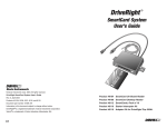
Includes:
SmartCard On-Board Reader (#8105)
SmartCard Desktop Reader (#8108)
SmartCards, Pack of 10 (#8112)
Starter Interrupter Kit (#8116)
Table Of Contents
Introduction . . . . . . . . . . . . . . . . . . . . . . . . . . . . . . . . . . . . . . . . . . . . . . . . . . 1
The SmartCard System . . . . . . . . . . . . . . . . . . . . . . . . . . . . . . . . . . . . . . . . . 1
On-Board Reader Installation . . . . . . . . . . . . . . . . . . . . . . . . . . . . . . . . . . . . 3
Connecting the On-Board Reader . . . . . . . . . . . . . . . . . . . . . . . . . . . . . . . . . 4
Mounting the On-Board Reader . . . . . . . . . . . . . . . . . . . . . . . . . . . . . . . . . . 5
Using the On-Board Reader . . . . . . . . . . . . . . . . . . . . . . . . . . . . . . . . . . . . . 9
Using the Desktop Reader . . . . . . . . . . . . . . . . . . . . . . . . . . . . . . . . . . . . . . 11
Installing the Starter Interrupter Kit . . . . . . . . . . . . . . . . . . . . . . . . . . . . . . 11
Specifications . . . . . . . . . . . . . . . . . . . . . . . . . . . . . . . . . . . . . . . . . . . . . . . 14
Contacting Davis Technical Support. . . . . . . . . . . . . . . . . . . . . . . . . . . . . . 14
Regulatory Compliance
E Mark
This Product complies with the essential protection requirements of the EC EMC Vehicle Directive 95/54/EC.
FCC Part 15 Class B Registration Warning
This equipment has been tested and found to comply with the limits for a Class B digital device, pursuant to Part 15 of the
FCC Rules. These limits are designed to provide reasonable protection against harmful interference in a residential installation. This equipment generates, uses, and can radiate radio frequency energy and, if not installed and used in accordance
with the instructions, may cause harmful interference to radio communications.
However, there is no guarantee that interference will not occur in a particular installation. If this equipment does cause harmful interference to radio or television reception, which can be determined by turning the equipment on and off, the user is
encouraged to try to correct the interference by one or more of the following measures:
• Reorient or relocate the receiving antenna.
• Increase the separation between the equipment and receiver.
• Connect the equipment into an outlet on a circuit different from that to which the receiver is connected.
• Consult the dealer or an experienced radio/TV technician for help.
Changes or modification not expressly approved in writing by Davis Instruments may void the warranty and void the user's
authority to operate this equipment.
IC: 378810-6328
EC EMC Compliance
This product complies with the essential protection requirements of the EC EMC Directive 89/336/EC.
For Products: #8105, 8108, 8112, 8116
Rev. A (4/18/06)
Davis Instruments Part Number: 7395.222
DriveRight SmartCard System User’s Guide
© Davis Instruments Corp. 2006. All rights reserved.
This product complies with the essential protection requirements of the EC EMC Directive 89/336/EC.
DriveRight is a registered trademark of Davis Instruments Corp. Velcro is a trademark of Velcro
Industries, Manchester, NH.
®
®
3465 Diablo Avenue, Hayward, CA 94545-2778 U.S.A.
510-732-9229 • Fax: 510-732-9188
E-mail: [email protected] • www.davisnet.com
®
The DriveRight SmartCard System
Introduction
®
The DriveRight SmartCard System allows you to download DriveRight data
from any DriveRight device using the SmartCard On-Board Reader (#8105),
transport it to a computer easily using the SmartCard Desktop Reader (#8108)
and SmartCards (#8112), and also transfer administrative data from the computer to the DriveRight.
The SmartCard System can also be used with the optional Starter Interrupter
Kit (#8116) to prevent unauthorized drivers from using a vehicle or vehicles.
The DriveRight Fleet Management Software (#8186) should be used to set up
and maintain the SmartCard System operations. It is also required to configure
the SmartCards. All DriveRight 600 (#8156) and 600E (#8126) models work
with the SmartCard system.
Before You Install
Because the specific installation of the SmartCard System hardware can vary
considerably from vehicle to vehicle, these instructions are intended to be a
general guide for the professional installer or experienced mechanic. We
strongly recommend that you read the entire manual before beginning the
installation. Be sure you understand each procedure thoroughly before starting
that procedure.
CAUTION: Installing SmartCard hardware or any of the DriveRight components in a vehicle
can be hazardous to both the installer and to the vehicle’s electrical system. This
manual assumes you are aware of the inherent dangers of working in and around
a vehicle and have a working understanding of electricity. If you are uneasy about
any part of the installation, please have an ASE-certified technician or professional
mechanic do the installation. Davis Instruments specifically disclaims any liability
for injury or loss resulting from the installation or use of DriveRight Products.
The SmartCard System
The SmartCard System consists of four products:
•
•
•
•
The SmartCard (#8112 - Pack of 10)
The SmartCard On-Board Reader (#8105) - Includes one SmartCard
The SmartCard Desktop Reader (#8108)
The Starter Interrupter Kit (#8116 - Optional)
SmartCard
The SmartCard is a small plastic card about the size of a credit card that contains a memory chip for storing and transporting all the DriveRight data easily.
A pack of 10 SmartCards (# 8112) is available for purchase.
1
The SmartCard System
The DriveRight Fleet
Management Software (FMS)
is used to configure the
SmartCard with pertinent
information, such as the
assigned vehicle, Driver ID,
and card type. There are two
card types that can be
assigned to a SmartCard:
• Driver SmartCard — Is
assigned to a driver and
contains a unique driver ID the DriveRight uses to verify authorized
drivers. The card contains the Driver ID and receives downloaded
information from the On-Board Reader by the push of a button. A single
driver card has the same memory size as a DriveRight 600/600E. It can be
worn on a lanyard, clipped to a belt, or carried in a wallet.
• Administrative SmartCard — Is assigned to a fleet manager or fleet
administrator. This card is used to configure a DriveRight device with all
the necessary administrative changes, including driver authentication and
threshold changes. The administrative card can also be used to download
DriveRight data from all DriveRight devices in a fleet when used in conjunction with the Palm Download Kit (#8181).
Note: Configure the SmartCard in the FMS software first before using the SmartCard in the
On-Board Reader.
SmartCard On-Board Reader
The On-Board Reader connects to the
DriveRight device in a vehicle. The
SmartCard is inserted into the OnBoard Reader’s slot before starting a
vehicle. The Driver ID automatically
relays to the DriveRight device for
authentication. If the optional Starter
Interrupter Kit is installed, the vehicle
is allowed to start for an authenticated driver. At the end of the trip, the
driver presses a button on the OnBoard Reader to automatically download data onto the SmartCard.
2
On-Board Reader Installation
SmartCard Desktop Reader
The Desktop Reader is connected to a
computer via a free USB port. The
Desktop Reader works in conjunction with the FMS software to download DriveRight data via the
SmartCard and to configure all the
SmartCards or DriveRight devices in
the fleet.
Starter Interrupter Kit
The Starter Interrupter Kit is an
optional device installed with the
On-Board Reader that allows
only authenticated users with
validated SmartCards to use and
operate their assigned vehicles.
The kit contains a 12-volt starter
interrupter relay that gets connected to the car’s starter circuit.
If a SmartCard with the assigned Driver ID to the vehicle is inserted into the
On-Board Reader, the vehicle is allowed to start. If an unauthenticated driver
or driver without a SmartCard tries to use the vehicle, the vehicle will not start.
On-Board Reader Installation
Components
The On-Board Reader comes with the components and hardware shown in the
illustration on the next page. Some of the hardware might not be used, depending on how the On-Board Reader is installed.
Note: Before installing the On-Board Reader, the DriveRight 600 or 600E device, as well as any
other optional accessories, such as the # 8157 GPS module for DriveRight 600 models,
and #8127/8128 GPS module for DriveRight 600E models, should be installed correctly.
See your device’s installation manual for more information.
3
Connecting the On-Board Reader
®
Velcro Tabs (6)
SmartCard
On-Board
Reader
Double-Sided Foam Tape (8)
SmartCard
5-1/2" Cable Ties
(8)
#6 X 1/2"
Flat Head
Self-Tapping
Screws
(3)
Connecting the On-Board Reader
The On-Board Reader is installed in series between the DriveRight 600 or
600E device and the DriveRight digital input adapter cable or GPS module.
Use the following diagram below to connect the On-Board Reader to the
DriveRight device and any other components in your system:
To Starter Interrupter
Relay Harness
(Optional)
SmartCard
On-Board
Reader
GPS or
Digital Input
Adapter Cable
DriveRight 600 or
DriveRight 600E
Device
To connect the On-Board Reader to your existing DriveRight system:
1. Disconnect the DriveRight device cable from the GPS module cable or
Digital Input Adapter Cable.
2. Connect the On-Board Reader’s female connector to the male connector
from the DriveRight device cable.
4
Mounting the On-Board Reader
3. Connect the On-Board Reader’s male connector to the female connector
attached to the GPS module cable or the Digital Input Adapter Cable.
See the diagrams below for help on disconnecting and connecting the cables
properly:
Disconnecting Cables:
Hold both cables by their connector housing and pull apart.
The housing of the male connector slides to separate the cables.
Connecting Cables:
Slide
Connector Housing
Hold the female connector and push the male connector from behind, allowing
its housing to slide back. The cables lock together when a connection is made.
Mounting the On-Board Reader
The On-Board Reader can be mounted to the dashboard or to another easy-toreach location in a vehicle in one of three ways:
• Mounting with the provided Velcro tabs
• Mounting with the provided double-sided foam tape tabs
• Mounting with an customer-provided mounting plate
Note: No matter which mounting option you decide to use, note that the card slot should be
facing the driver, with the indicator light and download button clearly visible.
If the On-Board Reader orientation needs to change to mount it and access it
easily, thread some or all of the cables through the grooves on the back of the
reader so that the reader lies flat once the cables are in place.
5
Mounting the On-Board Reader
Thread the DriveRight connector cable down
one of the large inner grooves. Thread the
GPS module or Digital Input connector cable
down the other large inner groove. Thread the
Starter Interrupter Cable down one of the
thinner outer grooves depending on your
wiring orientation.
Do this before mounting. Once your mounting option is in place, it may be hard to secure
the wires into the grooves.
Mounting with Velcro Tabs
The hardware kit contains six Velcro tabs for
attaching the On-Board Reader to the dashboard or some other accessible area in the
vehicle. To attach the Velcro tabs:
1. Make sure the back of the On-Board
Reader and the surface you are adhering
the On-Board Reader to are clean and
wiped of any dust or debris.
2. Remove the backing on one side of the
Velcro tabs.
3. Apply the Velcro tabs to the back of the
On-Board Reader. Davis recommends that
four of the Velcro tabs be placed between
the wire grooves next to each other.
4. Remove the backing from the other side of
the Velcro tabs and place on the dashboard
or designated area.
On-Board Reader Wiring Options
®
Velcro or
Double-Sided
Foam Tape
Mounting with Double-Sided
Foam Tape
The hardware kit contains eight double-sided
foam tape tabs for attaching the On-Board
Reader to the dashboard or some other accessible area in the vehicle. To attach the foam
tape:
Velcro or Double-Sided Tape Options
1. Make sure the back of the On-Board Reader and the surface you are
adhering the On-Board Reader to are clean and wiped of any dust or debris.
2. Remove the backing on one side of the double-sided foam tape tabs.
3. Apply the tabs to the back of the On-Board Reader.
4. Remove the backing from the other side of the foam tabs and place on the
dashboard or designated area.
6
Mounting the On-Board Reader
Mounting with Customer-Provided Mounting Plate
If the other mounting options do not work for you, you can create your own
mounting plate using the following diagram:
4" (102 mm)
Width
1/4" (7 mm)
Thick
1-1/2" (39 mm)
Height
This diagram depicts a mounting plate 4'' wide, 1-1/2'' tall, and 1/4'' thick. The
mounting plate sizing can vary depending on mounting and installation needs.
The one requirement for creating the mounting plate is that the inner holes
should be drilled so that their centers are spaced exactly 2.25'' (57.2 mm) away
from each other to line up with the pre-drilled holes on the back of the OnBoard Reader.
To ensure that the mounting plate lies flat on the mounting surface, the holes
should be created with countersinks so that the flat head self-tapping screws
lie flat in the mounting plate.
The outer holes should be spaced far enough from the inner holes that they are
accessed easily once the On-Board Reader is mounted on the plate.
.
7
Mounting the On-Board Reader
2.25"
(57 mm)
11/64" (4.4 mm)
Hole with Countersink
Template to scale
To install the optional
mounting plate:
#6 x 1/2" Self-Tapping Screws
1. Place the mounting
plate, with the preHoles for mounting
plate screws
drilled countersink
(screws not supplied)
holes facing outward,
on the back of the
On-Board Reader.
2. Line up the holes with
countersinks with the
pre-drilled holes on
the On-Board Reader
located on the outside
of the wire grooves.
3. Secure the mounting
plate on the On-Board
Reader using the #6
by 1/2'' self-tapping
screws.
4. Secure the On-Board Reader to the dashboard or other surface using the
outer holes on the mounting plate.
8
Using the On-Board Reader
Using the On-Board Reader
Logging In
To log in to the On-Board Reader, simply
insert the supplied SmartCard into the OnBoard Reader before starting up the vehicle.
For ease of use, you can log in with the
SmartCard in one of two ways, using Swipe
Mode or Leave-in Mode.
To log in using Swipe Mode, simply insert
the SmartCard, wait for the green indicator
light and remove the SmartCard within 5
seconds.
To log in using Leave-in Mode, insert the SmartCard in the On-Board Reader
and leave it there until the end of a trip.
The Driver ID is automatically relayed to the DriveRight device for authentication. The driver no longer needs to enter the Driver Code into the device.
If the Driver ID is accepted, one beep sounds followed by the green indicator
light. If the optional Starter Interrupter Kit is installed, the vehicle is enabled
to start. When login is successful, the green LED stays on as long as the vehicle is in motion. Otherwise, it goes off after 10 minutes to save power.
If the Driver ID is not authorized, two beeps sound and the red indicator lights.
If the optional Starter Interrupter Kit is installed, the vehicle is prohibited from
starting. A Driver ID is not authorized if the Driver ID on the SmartCard does
not match up to the driver list kept on the DriveRight device. If the SmartCard
also contains a vehicle list, both the vehicle and Driver ID on the SmartCard
must match that of the DriveRight device.
If the SmartCard is inserted incorrectly or if there is an error reading the
SmartCard, the yellow indicator lights. Reinsert the card and try again or see
your administrator if you are having difficulties.
Note: When the vehicle is moving, all SmartCard functions (logging in and out, downloading,
uploading, etc.) are disabled. If attempted, the red indicator lights and two short beeps
sound, indicating user error.
Logging Out
Logging out of the SmartCard On-Board Reader happens in one of two ways:
Auto Logout and Manual Logout.
If you are using the card in Swipe Mode to log in, the On-Board Reader will
initiate Auto Logout at the end of a trip. Auto Logout occurs automatically
after a preset amount of time has elapsed. The On-Board Reader automatically
9
Using the On-Board Reader
logs a user out in 10 minutes, but automatic logout time can be set to any time
period using the DriveRight FMS software.The Auto Logout time period is
stored on each SmartCard and can be set individually for every vehicle and
driver in the fleet. Auto Logout occurs if the time period elapses with no vehicle activity logged on the DriveRight device.
The Auto Logout timer is reset every time a driver has logged in, new vehicle
activity is recorded, or a download has occurred. To log out when the OnBoard Reader is in Swipe mode after a trip, insert the card and remove it again
after 5 seconds. The Driver ID and card are immediately logged out without
waiting for the time out period. Each time the SmartCard is inserted regardless
of log in mode, the previous driver is automatically logged out.
Note: The DriveRight Device also has an Auto Logout function that should be disabled before
using the On-Board Reader, especially the On-Board Reader’s Swipe Mode feature,
using the FMS software.
Manual Logout occurs when a driver leaves the SmartCard in the On-Board
Reader for the duration of a trip or succession of trips, then pulls the card out
of the reader when done.
If the logout is successful, the indicator light goes off. If the optional Starter
Interrupter Kit is installed, the vehicle’s starter is disabled until the driver is
logged in again using the SmartCard. If logout is unsuccessful, the red indicator lights (without any beeps). The red light stays on until a successful logout
is completed or after one minute.
Downloading Data to a SmartCard
To download DriveRight trip information to a SmartCard:
1. With the vehicle stopped and the motor off, press the download button on
the On-Board Reader. A blinking yellow light indicates that the download is
in progress.
2. Take the card out when the green indicator lights and one long beep sounds.
If the red indicator lights, the SmartCard did not download the information
successfully. Take the SmartCard out, reinsert it, and press the download
button again.
Note: Download cannot take place when the vehicle is in motion. The red indicator lights and
two short beeps sound if a download is attempted while the vehicle is moving.
Uploading Data from a SmartCard
Uploading Data is the act of uploading information from the SmartCard to the
DriveRight device. Uploading usually happens when an Administrative or
Driver SmartCard is used to transfer DriveRight settings to a DriveRight
device. The Driver SmartCard is used to change settings on only one DriveRi10
Using the Desktop Reader
ght. Use the Administrative SmartCard to change settings on multiple DriveRight devices in sequence.
To upload configuration information to a DriveRight:
1. With the vehicle stopped and the motor off, insert the administrative
SmartCard. A blinking yellow light indicates that the upload is in progress.
2. Take the card out when the green indicator lights.
If the red indicator lights and two short beeps sound, the SmartCard did not
upload the information to the DriveRight successfully. Take the SmartCard
out, and reinsert it.
Adjusting the Clock
If the DriveRight device’s internal clock does not display the right time, the
SmartCard can add to or subtract minutes from the DriveRight’s clock. See the
DriveRight Fleet Management Software User’s Manual or Online Help System for information on using the SmartCard to change clock settings.
Every time an administrative SmartCard is inserted, it adjusts the DriveRight’s
internal clock with the offset minutes set by the SmartCard.
The driver SmartCard adjusts the internal clock once.
Using the Desktop Reader
The Desktop Reader connects to any computer with a USB port and is compatible
with DriveRight FMS version 3.3 or later.
FMS sends and receives data to and from
the SmartCard via the Desktop Reader.
See the DriveRight Fleet Management
Software User’s Manual or Online Help
System for information on configuring a
SmartCard and downloading data from a
SmartCard.
Note: Install the DriveRight FMS first before connecting the Desktop Reader to a computer, and
follow the instructions for installing and connecting the Desktop Reader.
Installing the Starter Interrupter Kit
The Starter Interrupter Kit is an optional feature that, when installed with the
SmartCard On-Board Reader, prevents the vehicle from starting if a driver
tries to use a vehicle without a SmartCard or uses a vehicle that the driver is
not authorized to use.
11
Installing the Starter Interrupter Kit
Components
The Starter Interrupter Kit comes with the components and hardware shown in
the following illustration. Make sure you have all the necessary components
before proceeding:
Relay with Harness
Butt Splices
(16-22AWG)
In-Line Splices
#8 x 3/4"
Sheet Metal
Screw
#8 Flat
Washer
Installation and Wiring
The Starter Interrupter Kit is installed between the On-Board Reader and the
vehicle’s starter switch wire. Use the diagram on the next page to connect the
Starter Interrupter Kit to the On-Board Reader and the vehicle’s ignition system.
12
Installing the Starter Interrupter Kit
.
Starter
60 Amp
Solenoid
Starter Power
Key Switch
12V
Starter Switch Wire
Butt
Splice
Butt
Splice
In-Line
Splice
Red Wire
Green Wire
STARTER
INTERRUPTER
RELAY
#8116
Yellow Wire
Green Wire
Butt
Splice
Gray Wire
To connect the Starter Interrupter Kit to the On-Board Reader and the Vehicle’s Ignition System:
1. Find your vehicle’s fuse box and remove the fuse for the 12-volt line before
installing the Starter Interrupter Kit.
2. Splice the Starter Interrupter Kit’s switched 12-volt wire into the 12-volt
starter wire.
3. Make the other splices in the diagram using the supplied In-Line and Butt
Splices as necessary.
Crimp Tool,
22-18AWG Position
(red dot)
In-Line Splice
Stripped Wire,
Trimmed off Flush
3/16" - 1/4"
(5 - 6 mm)
Butt
Splice
Switched 12V
Wire
Red Wire from
Interrupter Relay
In-Line Splice
3/16" - 1/4"
(5 - 6 mm)
Butt Splice
13
Specifications
Specifications
On-Board Reader (#8105)
Operating Temperature. . . . . . .
Storing Temperature . . . . . . . . .
Primary Power . . . . . . . . . . . . .
Dimensions (Unit Only) . . . . . .
Dimensions (Product Package) .
Weight (Unit Only) . . . . . . . . . .
Weight (Product Package) . . . .
.
.
.
.
.
.
.
. -40º F to +185º F (-40º C to +85º C)
. -40º F to +185º F (-40º C to +85º C)
. 11 to 18 VDC (12 VDC nominal)
. 2.88'' x 1.25'' x 4.13'' (73 mm x 31 mm x 105 mm)
. 9.63'' x 1.75'' x 6.38'' (245 mm x 45 mm x 162 mm)
. 4.60 oz. (.13 kg)
.9.4 oz. (.26 kg)
.
.
.
.
.
.
.
.
.
.
. -0º F to +122º F (-17º C to +50º C)
. -0º F to +122º F (-17º C to +50º C)
. Supplied by USB
. USB
. 4.5' (1.3 m)
. Windows 98 SE, ME, NT 4.0, NT2000, XP
. 4.00'' x 3.00'' x 0.75'' (101 mm x 76 mm x 19 mm)
. 6.25'' x 4.25'' x 2.13'' (158 mm x 108 mm x 54 mm)
. 3.40 oz. (.096 kg)
.5.44 oz. (.154 kg)
.
.
.
.
. -0º F to +140º F (-5º C to +60º C)
. -0º F to +140º F (-5º C to +60º C)
. 3.38'' x 2.13'' x 0.01'' (101 mm x 76 mm x 19 mm)
. 0.19 oz. (.005 kg)
Desktop Reader
Operating Temperature. . . . . . .
Storing Temperature . . . . . . . . .
Primary Power . . . . . . . . . . . . .
Computer Interface . . . . . . . . . .
Computer Cable Length . . . . . .
Operating System . . . . . . . . . . .
Dimensions (Unit Only) . . . . . .
Dimensions (Product Package) .
Weight (Unit Only) . . . . . . . . . .
Weight (Product Package) . . . .
SmartCard
Operating Temperature.
Storing Temperature . . .
Dimensions. . . . . . . . . .
Weight . . . . . . . . . . . . .
.
.
.
.
.
.
.
.
.
.
.
.
.
.
.
.
.
.
.
.
.
.
.
.
Note: In high-temperature environments, use the SmartCard in swipe mode and store the card
in a climate-controlled environment.
Contacting Davis Technical Support
If you have questions about the SmartCard System, or encounter problems
installing or using the SmartCard System, please contact Davis Technical Support. Most questions can be answered on the phone.
Note: Sorry, we are unable to accept collect calls.
(510) 732-7814 – Monday through Friday, 7:00 a.m. to 5:30 p.m. Pacific Time
(510) 670-0589 – Fax to Technical Support
[email protected] – E-mail to Technical Support
[email protected] – E-mail to Davis Instruments
www.davisnet.com – Product documentation is available on the DriveRight
Support section of our web site. Watch for FAQs and other updates.
14