1
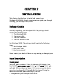
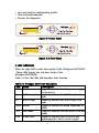
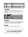
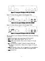
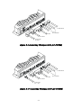
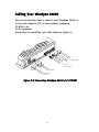
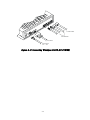
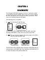
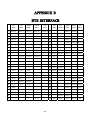
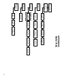
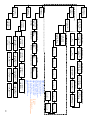
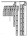
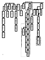
Atrie WireSpan 3000/3000E MODEM User's Manual WireSpan 3000/3000E USER'S MANUAL ATRIE WireSpan 3000/3000E USER'S MANUAL (Version 3) ATRIE TECHNOLOGY INC. 10 Floor,14 , Lane 609, Sec.5, Chung Hsin Rd., San Chung City, Taipei Hsien, Taiwan 241, R.O.C. TEL:+886-2-29995155 FAX:+886-2-29994960 Web:www.atrie.com.tw Mail:[email protected] th (C) Copyright 2001 ATRIE TECHNOLOGY INC. TABLE OF CONTENT CHAPTER 1 INTRODUCTION Overview.................................................1-1 Applications...................................................1-3 CHAPTER 2 INSTALLATION Package Contain......................................2-1 Panel Description...................................2-1 Cabling Your WireSpan 3000 ..........................2-5 CHAPTER 3 GETTING START The Front Panel LCD Controller........................3-1 Menu Tree Operation......................................3-3 The Console Port Operation..... ................. ............... 3-22 CHAPTER 4 DIAGNOSTIC APPENDIX A SPECIFICATION APPENDIX B DTE INTERFACE APPENDIX C MENU TREE CHAPTER 1 INTRODUCTION Overview The WireSpan 3000/3000E is a HDSL (High-bit-rate Digital Subscriber Line) digital modem. It provides full duplex (bi-directional) 1.544Mb/s (T1) or 2.048Mb/s (E1) transmission capability over two non-loaded two-wire metallic cable pairs. Specifically, bi-directional data at a rate of 784kb/s or 1168kb/s is transmitted and received on each pair. Figure 1-1, 1-2 illustrated a generic dual duplex HDSL system. Each of the High-bit-rate Terminal Units (HTU), at either the Central Office (HTU-C) or the Remote Distribution (HTU-R) location, consists of two pairs of digital transmitter/receiver ("transceiver"), each connected by a two-wire CSA(Carrier Serving Area) compatible loop. WireSpan 3000 supports data rates of Nx64 Kbps up to 2.048 Mbps. The DTE interface supported are EIA RS-530/V.35/RS-449/X.21. DTE interface for data transmission support drop & insert functions. This programmable Nx64K feature accordingly makes our WireSpan 3000 E1 HDSL DSU/CSU the best choice on applications such as INTERNET access and leased lines service. But this feature does not provide in WireSapn 3000E, the difference show in Figure 1-1, 1-2 for reference. 1-1 HTU-C HTU-R Loop1 1.544Mbps or 2.048Mbps T1/E1 Interface Circuit N x 64K Transceiver Loop2 T1/E1 Interface Circuit Transceiver N x 64K T1/E1 Interface 1.544Mbps or 2.048Mbps T1/E1 Interface RS-530/V.35 RS-449/X.21 RS-530/V.35 RS-449/X.21 DTE DTE Figure 1-1 WireSpan 3000 HTU-C HTU-R Loop1 1.544Mbps or 2.048Mbps T1/E1 Interface Circuit Transceiver Transceiver Loop2 T1/E1 Interface T1/E1 Interface Circuit 1.544Mbps or 2.048Mbps T1/E1 Interface Figure 1-2 WireSpan 3000E The HDSL technology provides a transport method that enables the transmission of data rates up to 2.320Mb/s over long distances of unconditioned, voice-grade twisted-pair wire. Although the exact distances achievable are dependent upon the exact data rate required (cable conditions and configurations, presence and length of bridge taps, and severity of external noise sources) distances of between 3.7Km(10,000 feet) and 4.5Km(14,850 feet) have been demonstrated. Please refer to Appendix A for the detail 1-2 specification of the WireSpan 3000. Applications z z z z z Voice Pair Gain Systems T1/E1 Extend High-Speed Digital Modems Personal Communication Systems (PCS) Wireless PBX 1-3 CHAPTER 2 INSTALLATION This chapter describes how to install and connect your WireSpan 3000/3000E. Step-by-step instructions guide you through installing your WireSpan 3000/3000E. Package Contain Carefully unpacking your WireSpan 3000. The package should contain the following items: 1. The WireSpan 3000. 2. One power cable. 3. One user's manual 4. One DTE Interface cable For WireSpan 3000E. The package should contain the following items: 1. The WireSpan 3000E. 2. One power cable. 3. One user's manual Please contact your dealer if there are any missing or damaged parts. Panel Description Front panel The front panel contains a 2 line ∗16 character LCD display, four keys labeled EXIT, ENTER, LEFT arrow "<", and RIGHT arrow ">" ; and eight LEDs as shown in Figure 2-1. You can access the device menu tree (see Appendix C) through this front panel. Using the menu tree and front panel control keys, you can: z Configuration your WireSpan 3000 device 2-1 z z z Save and load the configuration profile View status information Execute the diagnostic HDSL NTU Figure 2-1 Front Panel E HDSL Termination Unit Figure 2-2 Front Panel 1. LED Indicators There are eight LEDs on the front panel of the WireSpan 3000/3000E . These LEDs display the real-time status of the WireSpan 3000/3000E. Table 2-1 lists the LEDs and describes their function. Table 2-1 WireSpan 3000 LED Description LED Name Description PWR Power L1 HDSL Loop1 L2 HDSL Loop2 ALM Alarm TST Test Mode SYN Frame Sync Lights to indicate that the power is apply to the device Lights to indicate that HDSL loop1 is in sync Lights to indicate that HDSL loop2 is in sync Lights to indicate the alarm conditions in HDSL Lights to indicate that the device is in test mode Lights to indicate that the device has synchronized to the E1 receive signal 2-2 AIS Alarm Indication Signal YEL Yellow Alarm framing Lights to indicate the presence of an alarm indication signal on the E1 receive signal Lights to indicate the presence of a yellow alarm on the E1 receive signal 2. Control Keys The front panelís four control keys allow you to access the configuration menus, options, and settings that appear in the front panel display. Table 2-2 lists and describes the function of each control key. Table 2-2 Front Panel Keys Keys Functions EXIT ENTER LEFT RIGHT Exit to upper menu or abort execution command Enter menu or confirm your choice Select next left menu Select next right menu 3. LCD Display The front panel LCD display is a 2*16 alphanumerical display. It displays the status and configurations of the WireSpan 3000. Please refer to Chapter 3 for detail operation of the LCD display. Rear Panel Figure 2-3 shows the rear panel of the WireSpan 3000. CON ON OFF DTE T1/E1 RX T1/E1 TX T1/E1 AC Figure 2-3 rear panel WireSpan 3000 (AC POWER) Figure 2-4 shows the rear panel of the WireSpan 3000E. 2-3 HDSL OFF T1/E1 RX CON ON T1/E1 TX T1/E1 HDSL AC Figure 2-4 rear panel WireSpan 3000E (AC POWER) Figure 2-5 shows the rear panel of the WireSpan 3000. FG DC-48V CON ON DTE T1/E1 RX T1/E1 TX T1/E1 HDSL OFF Figure 2-5 rear panel WireSpan 3000 (DC POWER) Figure 2-6 shows the rear panel of the WireSpan 3000E FG DC-48V ON T1/E1 RX CON T1/E1 TX T1/E1 HDSL OFF Figure 2-6 rear panel WireSpan 3000E (DC POWER) The rear panel of your WireSpan 3000/3000E contains the following connectors: z AC: AC Power Input (auto-range from AC 90V to 260V) z DC: DC Power Input (range from DC -36V to -72V) z HDSL: HDSL Line Interface. Please refer to Figure 2-3 for pin definition. z E1: E1 Line Interface. Include 75 Ohm for Coaxial Cable and 120 Ohm for Twisted Pair . Please refer to Figure 2-4 for pin definition. z DTE: DTE Interface. Please refer to Appendix C for pin definition Note: this connector does not include in WireSpan 3000E. z CON: Console Port 2-4 Note: 1: TIP2 for HDSL loop2 2: RING2 for HDSL loop2 4: TIP1 for HDSL loop1 5: RING1 for HDSL loop1 Figure 2-5 RJ-45 for HDSL Line Interface Note: 1: Receive TIP1 for E1 loop 2: Receive RING1 for E1 loop 4: Transmit TIP2 for E1 loop 5: Transmit RING2 for E1 loop 7: Ground 8: Ground Figure 2-6 RJ-48 C for E1 Line Interface Cabling Your WireSpan 3000 This section describes how to connect your WireSpan 3000 to: (1) A personal computer (PC) or data terminal equipment (2) HDSL Line (3) E1 equipment (4) DTE Interface Instructions for installing each cable shown in Figure2-5 2-5 SL HD /E T1 /E T1 1 1 TX /E1 T1 RX E DT M CO To Other HDSL ON AC F OF To DTE To E1 interface To Console To AC Power 90 ~ 260 V Figure 2-9 Connecting WireSpan 3000 (AC POWER) SL HD /E1 T1 /E1 T1 TX /E T1 1 RX E DT FG DC To Other HDSL 8V - 4 ON F OF To DTE To E1 interface To Console To DC Power -36 ~ -72 V Figure 2-10 Connecting WireSpan 3000 (DC POWER) 2-6 Cabling Your WireSpan 3000E This section describes how to connect your WireSpan 3000E to: (1) Personal computer (PC) or data terminal equipment (2) HDSL Line (3) E1 equipment Instructions for installing each cable shown in Figure2-6 SL HD /E1 T1 /E1 T1 TX /E1 T1 RX M CO To Other HDSL ON AC F OF To E1 interface To Console To AC Power 90 ~ 260 V Figure 2-11 Connecting WireSpan 3000E (AC POWER) 2-7 SL HD /E1 T1 /E1 T1 TX /E1 T1 RX FG DC 8V - 4 To Other HDSL ON F OF To E1 interface To Console To DC Power -36 ~ -72 V Figure 2-12 Connecting WireSpan 3000E (DC POWER) 2-8 CHAPTER 3 GETTING START There are two methods to control the WireSpan 3000/3000E ,one is using the front panel LCD controller; the other is using the console port on the rear panel. The Front Panel LCD Controller The front panel LCD controller consists of the LCD display and front panel switches. The menu tree consists of several categories. Each category has several options (STATUS, CONFIGURE, DIAGNOSTIC, etc.) Many of these options are configurable, while others indicate the device status. Most options contain several selectable settings. Each of the settings affects various operating characteristics. Using the front panel control keys, you can easily access the options and settings under each category. The following sections describe the major options of the menu tree. Please refer to Appendix C for detail structure of the menu tree. Main Menu The main menu shows up right after power on selftest. The main menu displays the current status of the device. The main menu shows as the following: HTU-R 2E1 1 1 6 8 120 OHM HDB3 HTU-C or HTU-R: To indicate current terminal type is local (HTU-C) or remote (HTU-R). 2E1: To indicate two-pair E1 operation. 1168: date rate on per pair HDSL loop. 3-1 120 OHM: To indicate E1 interface impendence such as 120 OHM or 75 OHM or DISABLE (when E1 interface unused ). HDB3: To indicate line coding method such as HDB3 or AMI when in non loop back mode .To indicate loop back mode such as LL or DL. There are four categories under main menu: Status, Configure, Diagnostic and Profile. The function of every categories are describe below: Status This category shows the Loop Status, E1 Status, Monitor and Rest. Loop Status : Displays the current HDSL loop status of the WireSpan 3000/3000E. The status includes: signal in sync/out of sync,CRC error, far end block error, input signal level, input DC offset level, far end signal attenuation, noise margin,LOS condition and LOST condition. DTE Status : Displays the DTE interface status of the WireSpan 3000.The status includes: control signal status, timeslot status. E1 Status : Displays the E1 loop status of the WireSpan 3000/3000E The status are: Received Loss Of Signal, Received Loss Of Frame Alignment, Received Alarm Indication Signal, Received Yellow Alarm, Framing Bit Error Counter,CRC Error Counter, Severely Error Frame Counter, Loss Of Frame Counter, Line Violation Counter, Bipolar Violation and Far End Block Error Counter Monitor : This category monitors the performance of the E1 or HDSL line. Cls Err Cntr : This category clears the error counter. Configure The configure category configures the WireSpan 3000/3000E. DTE Setup : Configures the DTE parameters, such as: DTE act state, Clko polarity, dato polarity, DCD ,DSR, 3-2 CTS option, Interface type. E1 Setup : Aux : Ts Mapping : Sys Rst : Configures the E1 line parameters, such as: framing, cable length and terminal type. Setup the auxiliary parameters, including: clock source, keylock enable and keylock password. This option maps the appropriate time slots to the respective DTE port. Rests the whole WireSpan 3000/3000E. Diagnostic The diagnostic allows user to do variety of loop back to assist user in isolating network problem. Note : you must choose ”E1 Terminal” mode when you use DTE Port and don't use E1 port in HTU-R side Profile The WireSpan 3000/3000E supports 5 user profiles to save for future use. Also provide 10 factory default profiles to load. Menu Tree Operation STATUS MENU [MAIN] STATUS C This Menu shows the loop STATUS of HDSL;E1 STATUS and other status display. CONFIGURE MENU [MAIN] C CONFIGURE You can configure the WireSpan 3000/3000E through this menu, to get the best performance. 3-3 DIAGNOSTIC MENU [MAIN] C DIAGNOSTIC This menu provide self-test,helping user to find out the problem and fix it. PROFILE MENU [MAIN] C PROFILE This menu provides the user 5 user profile to save or load,also provide the factary setting. STATUS MENU [MAIN] C STATUS Press ENTER key to enter loop status Menu. < STATUS > LOOP STATUS This screen shows the HDSL Loop status,press ENTER to show Loop1, Loop2 STATUS. <<HTU STATUS >> L1:ON L2:OFF ON: on Line OFF: off Line Press Right key shows the CERR STATUS. HDSL CRC ERROR COUNT STATUS SCREEN 3-4 <<HTU STATUS >> CERR Press ENTER to display the Loop1,Loop2 CRC ERROR count. CERR: CRC ERROR COUNT L1:*** CERR L2:*** Press EXIT to return to CERR STATUS screen,Press Right key to enter FEBE STATUS screen. FAR END BLOCK ERROR COUNT DISPLAY SCREEN <<HTU STATUS >> FEBE FEBE: Far-End Block Error L1:*** FEBE L2:*** This screen displays the HDSL Loop1 and Loop2 Far-End Block Error count . Press Exit key to return to FEBE STATUS screen, press Right key to show the Input Signal Level screen. INPUT SIGNAL LEVEL DISPLAY <<SIGNAL LV >> L1:** L2:** dB SIGNAL LV: Input Signal Level This screen shows the current Input Signal Level of Loop1, Loop2. Press Right Key shows the DC OFFSET Level display. DC OFFSET LEVEL DISPLAY 3-5 <<DC OFFSET >> L1:***L2:***dB This screen shows the HDSL Loop1, Loop2 DC OFFSET level. Press Right key shows the FESA STATUS. FAR-END SIGNAL ATTENUATION DISPLAY << FESA >> L1:***L2:***dB FESA=Far-End Signal Attenuation This screen shows the HDSL Loop1, Loop2 FAR-END SIGNAL ATTENUATION. Press Right key to show the NOISE MARG screen. NOISE MARGIN DISPLAY <<NOISE MARG>> L1:*** L2:***dB NOISE MARG=Norise Margin This screen shows the HDSL Loop1, Loop2 receiving Noise Margin. Press Right key to show the LOS COND Display. LOS CONDITION DISPLAY << LOS COND >> L1:ON L2:OFF LOS COND=LOS Condition LOST CONDITION DISPLAY << LOST COND >> L1:ON L2:OFF LOST COND=LOST Condition 3-6 DTE STATUS MENU <STATUS> DTE This screen displays WireSpan 3000's DTE interface signal status and timeslot status. Press ENTER to show the signal status. THE DTE CONTROL SIGNAL STATUS SCREEN 1:CTS_ DSR_ 1:RTS_ DTR_ This status screen shows the CTS,DSR,RTS,DTR status of the DTE interface. Press ENTER to show the timeslot status. THE DTE TIMESLOT STATUS DISPLAY SCREEN <<DTE TS>> TIMESLOT STATUS Press ENTER to show the timeslot status. * 00 * 01 * 02 * 03 There are 32 timeslots in the DTE interface, from 00 to 31, each timeslot with 64 kps band width * mark represents enable. Press Left or Right key to see other timeslot status. E1 STATUS MENU < STATUS> E1 STATUS In E1 status MENU, you can see the E1 signaling status. Press ENTER to show each signaling status. 3-7 E1 LOCAL RECEIVING RLOS* AIS_ LOF* YEL_ RLOS = Receive Loss Signal LOF = Loss Frame AIS = Alarm Indication Signal YEL = Yellow There will be * mark shown beside each alarm if present. LOCAL LINE STATUS BPV:_ TSHORT:_ BPV = Bipolar Violation TSHORT = Transmit Short There will be * mark shown beside each alarm if present. FRAMING ERROR AND CRC ERROR COUNTER FERR:*** CERR:*** FERR = Framing Error count CERR = CRC Error count LOF:* SEF:* LOF = Loss of Frame count SEF = Severely Loss of Frame count LCV :*** FEBE:*** 3-8 LCV = Line Code Violation count FEBE = Far-End Block Error count PERFORMANCE MONITOR <STATUS> PERF MONITOR E1 OR HDSL PERFORMANCE MONITOR <<PERF>> E1* HDSL The performance monitor shows the E1 and HDSL Receiving signal performance. Due to the size of the LCD display, the result will be shown on the CONSOLE port. Put the * mark on the E1 or HDSL and press the ENTER key to enter the performance screen. HDSL PERFORMANCE MONITOR (15 MINUTES) <<<HDSL PERF>>> 15M ES-CRC 15M ES-CRC: 15 MINUTE ERROR SECOND-CRC The scecond count of CRC error in each second during last 15 minutes.Press ENTER key to enter Loop1,Loop2 performance selecting screen. <<<<15M ES>>>> L1:* L2: Select the desire Loop1 or Loop2, press ENTER to get the performance screen from console port. HDSL SEVERELY PERFORMANCE MONITOR (15 MINUTES) <<<HDSL PERF>>> 15M SES-CRC 3-9 15M ES-CRC: 15 MINUTES SEVERELY ERROR SECOND-CRC The second count of CRC error more than 30% in each second during last 15 minutes.Press ENTER key to show Loop1,Loop2 performance selecting screen. <<<<15M SES>>>> L1:* L2:* Select the desire Loop1 or Loop2. Press ENTER key to get the performance screen from console port. HDSL PERFORMANCE MONITOR (24 HOURS) <<<HDSL PERF>>> 24H ES-CRC 24H ES-CRC: 24 HOURS ERROR SECOND-CRC Press ENTER key to select the Loop1 or Loop2 performance monitor. <<<<24H ES>>>> L1:* L2: Select the desire Loop1 ot Loop2 to get the performance screen from CONSOLE port. HDSL SEVERELY PERFORMANCE MONITOR (24 HOURS) <<<HDSL PERF>>> 24H SES-CRC 24H SES-CRC:24 HOURS SEVERELY ERROR SECOND Press ENTER key to select the Loop1 or Loop2 performance monitor. <<<<24H SES>>>> L1:* L2: 3-10 Select the desire Loop1 or Loop2 to get the performance screen from CONSOLE port. E1 PERFORMANCE MONITOR (15 MINUTES) <<<E1 PERF>>> 15M ES-CRC 15M ES-CRC:15 MINUTES ERROR SECOND-CRC E1 SEVERELY PERFORMANCE MONITOR (15 MINUTES) <<<E1 PERF>>> 15M SES-CRC 15M SES-CRC:15 MINUTES SEVERELY ERROR SECOND-E1 E1 PERFORMANCE MONITOR (24 HOURS) <<<E1 PERF>>> 24H ES-CRC 24H ES-CRC: 24 HOURS ERROR SECOND-E1 E1 SEVERELY PERFORMANCE MONITOR (24 HOURS) <<<E1 PERF>>> 24H SES-CRC 24H SES-CRC: 24 HOURS SEVERELY ERROR SECOND-E1 CLEAR ERROR COUNTER <STATUS> CLS ERR CNTR This screen clears all the error counter. 3-11 <<CLS CNTR>> YES* NO Slect YES and press ENTER key will clear all the error counter. CONFIGURE MENU [ MAIN MENU ] CONFIGURE DTE CONFIGURE MENU (THIS MENU EFFECT ONLY IN WireSpan 3000 MODEL) <CONFIGURE> DTE This Menu can activate, configure the DTE port. DTE PORT ACTIVATE <<SETUP DTE>> DTE ACT STATE This screen can activate the DTE port. All the configuration must activate the DTE port to in effect. <<<DTE ACT>>> ON* OFF Slect ON to activate the DTE port, OFF to inactivate the DTE port. CLOCK OUTPUT POLARITY <<SETUP DTE>> CLKO POLARITY This screen selects the polarity of the clock output. 3-12 <<<CLKO INV>>> NORM* INV* Select the Normal or Inverse output of clock signal. DATA OUTPUT POLARITY <<SETUP DTE>> DATO POLARITY This screen selects the polarity of data output. <<<DATO INV>>> NORM* INV* Select the Normal or Inverse output of data signal. DCD OPTION <<SETUP DTE>> DCD OPTION Press ENTER key to select DCD option. <<<DCD>>> ON* OFF Select the desire option (ON or OFF) for DCD signal. DSR OPTION <<SETUP DTE>> DSR OPTION Press ENTER key to select DSR option. <<<DSR>>> 3-13 ON* OFF Select the desire option(ON or OFF) for DSR signal. CTS OPTION <<SETUP DTE>> CTS OPTION Press ENTER key to select CTS option. <<<CTS>>> ON* OFF Select the desire option (ON or OFF) for CTS signal. DTE INTERFACE SELECT <<SETUP DTE>> INF TYPE There are EIA530 or V.35 for Interface selection. <<<INF TYPE>>> EIA530* V.35* Use Left or Right key to select interface. E1 CONFIGURE MENU <CONFIGURE> E1 SETUP This screen can configure the E1 parameter. Press ENTER to enter E1 Framing setup screen. E1 FRAMING SETUP SCREEN 3-14 <<E1 SETUP>> FRAMING Press ENTER to select E1 Framing. E1 FRAMING <<<FRAMING>>> PCM31 CCS Press Left or Right key to select PCM31 CCS or PCM31 CCS CRC or PCM30 CAS CRC or UNFRAME. <<<FRAMING>>> PCM31 CCS CRC <<<FRAMING>>> PCM30 CAS <<<FRAMING>>> PCM30 CAS CRC <<<FRAMING>>> UNFRAME E1 INTERFACE SELECT <<E1 SETUP>> INTERFACE Select the desire Interface for E1. The WireSpan 3000 provide RJ45 with 120 Ohm or BNC connector with 75 Ohm. Press ENTER to select. Use the Left or Right key to select then press ENRER to confirm. <<<INTERFACE>>> 120 OHM TP 3-15 <<<INTERFACE>>> 75 OHM COAXIAL <<<INTERFACE>>> DISABLE E1 HTU TYPE SELECT <<E1 SETUP>> HTU TYPE Use this screen to select central or remote. Two connecting modems must be set to one central and the other remote, otherwise it will not connect. Press ENTER key to select. Use the Left or Right key to select then press ENTER to confirm. <<<HTU TYPE>>> HTU-C* HTU-R E1 RECEIVE LINE INTERFACE UNIT SELECT <<E1 SETUP>> RLIU RLIU=RECEIVE LINE INTERFACE UNIT <<<RLIU>>> LH* SH LH=LONG HAUL SH=SHORT HAUL According the distance of the two Unit to select LONG HAUL or SHORT HAUL. LONG HAUL will modify the distortion wave form to get better performance in long distance communcation. E1 IDLE CODE SELECT <<E1 SETUP>> 3-16 IDLE CODE There are two idle codes for selection. Press ENTER to select. <<<E1 SETUP>>> 7F* FF Use Left or Right key to select "7F" or "FF" idle code. E1 LINE CODING SELECT <<E1 SETUP>> LINE CODING There are two methods of line coding. Press ENTER to select. <<<CODING>>> AMI* HDB3 Use Left or Right key to select AMI or HDB3 line coding. AUXILIARY CONFIGURE MENU <CONFIGURE> AUX This MENU configure the clock source, keylock functions. CLOCK SOURCE SELECT << AUX >> CLOCK SOURCE There are HDSL, E1 INTERNAL, DTE clock sources. Use Left or Right key to select desire clock source. <<<CLK SRC>>> HDSL 3-17 <<<CLK SRC>>> E1 <<<CLK SRC>>> INTERNAL <<<CLK SRC>>> DTE KEYLOCK SETTING <<AUX>> SET KEYLOCK This screen allows user to lock the four front panel keys. You must key in password before activate, the keylock function. Use Left or Right key to select keylock ON/OFF. <<<KEYLOCK>>> ON OFF* KEYLOCK PASSWORD SETTING <<AUX>> KEYLOCK PW The password contains ten numerical charactors. You must enter 10 digit of number. If you want to change old password, you have to enter old password first, then enter the new password. <<<PWD ?>>> NEW: <<<<PWD ?>>>> OLD: 3-18 TIMESLOT MAPPING (WireSpan 3000 ONLY) <CONFIGURE> TS MAPPING The WireSpan 3000 provides drop & insert function. In this function , it allows user to asign every 64 kpps bandwidth to be used in DTE port. Please note that each HTU-C and HTU-R to be connected must be asigned in same Timeslot Mapping. X * 00 01 02 03 Select the desire timesolt and press ENTER to enter asign screen. Set to DTE to asign and set to IDL to unasign. <<<TS DTE * 1>>> IDL ALL TIMESLOT MAPPING (WireSpan 3000 ONLY) <<TS MAPPING>> ALL TIMESLOT If you want to asign or unasign all the 32 timeslots, you can use ALL TIMESLOT function to asign or unasign all the timeslot in the same time. <<ALL TS >> DTE* IDL SYSTEM RESET <CONFIGURE> SYS RST Press ENTER key to enter SYSTEM RESET screen. 3-19 <<SYS RST>> YES* NO Use Left or Right key to select YES then press ENTER. DIAGANOSTIC MENU <DIAGNOSTIC> TEST MODE Through the diagnostic, the user can separate and fix the communication problem. There are three loopback test. Detail test description will be found on Chapter 4. Local E1 and HDSL LOOP BACK <<TEST MODE>> LLB Press ENTER to activate the test. Press ENTER then Left or Right key to TEST MODE DISABLE screen to end test. REMOTE E1 and HDSL LOCAL LOOP BACK << TEST MODE >> DLB Press ENTER to activate the test. Press ENTER then Left or Right key to TEST MODE DISABLE screen to end test. REMOTE HDSL LOOP BACK << TEST MODE >> RLB Press ENTER to activate the test. Press ENTER then Left or Right key to TEST MODE DISABLE screen to end test. 3-20 << TEST MODE >> DISABLE PROFILE MENU [MAIN] PROFILE There are ten preset profiles for user to load, and five user profiles can be saved by user for later load. LOCAL PROFILE < PROFILE > LOAD 1 <<LOAD>> 2 3* 4 5 Use Left or Right key to select profile and press ENTER to load. SAVE PROFILE < PROFILE > SAVE There are five profile can be saved. <<SAVE>> 1 2 3* 4 5 Use Left or Right key to select profile and press ENTER to save. LOAD DEFAULT < PROFILE > LOAD DEFAULT 3-21 There are ten factary default for user to load. Use Left or Right key to select and ENTER to load. <<1:HTU-C>> CAS+CRC 120 <<2:HTU-R>> CAS+CRC 120 <<3:HTU-C>> CAS+CRC 75 <<4:HTU-R>> CAS+CRC 75 <<5:HTU-C>> CAS+CRC 120 <<6:HTU-C>> CRC4 120 <<7:HTU-C>> UNFRAME 120 <<8:HTU-R>> CAS+CRC 75 <<9:HTU-R>> CRC4 75 <<10:HTU-R>> UNFARME 75 The Console Port Operation The rear panel contains a DB-9 console port, it allows user to use a VT-100 or ANSI terminal for system configuration, diagnostics, 3-22 polling status, etc. Table 3-1 lists and describes the function of each key. Keys UP DOWN LEFT RIGHT ENTER (RETURN) Functions Exit to upper menu Enter menu or confirm your choice Select next left menu Select next right menu Refresh console screen and exit to upper menu Table 3-1 the function of each key Table 3-4 lists and describes the parameter of the console port. Please adjust familiar Terminal Emulator Software according to the Table 3-4. Parameter Value Speed (Baud Rate) 115200 Data Bits 8 Parity None Stop Bits 1 Terminal Emulation VT-100 or ANSI Table 3-4 Console Port Setting 3-23 CHAPTER 4 DIAGNOSTIC The WireSpan 3000/3000E supports a variety of loop back to assist you in isolating network problem. These tests can be used to analyze the HDSL line and the local and remote E1 HDSL performance. These tests can be initiated from the front panel. The following tests are available: z LLB: Tests the local E1 and DTE loop Local Side Data Equipment E1 HDSL The data block will be looped back at the local HDSL end of the WireSpan 3000/3000E to Verify the local circuit (E1 and DTE). z DLB: This test examines transmit and receive circuit of the HTU-C and HTU-R and the HDSL loop. Remoe Side Data Equipment E1 HDSL Local HDSL Device HDSL E1 Remote HDSL Device The data block will go through remote WireSpan 3000/3000E (HTU-R) and loop back at local HDSL end of the WireSpan 3000/3000E (HTU-C) to verify the remote circuit and the HDSL line. 4-1 z HDSL RLB: (HTU-C mode only) This test examines transmit and receive circuit of the HTU-C and HTU-R and the HDSL loop. E1 HDSL HDSL HTU-C E1 HTU-R The data block will go through local WireSpan 3000/3000E (HTU-C) and loop back at remote HDSL end of the WireSpan 3000/3000E (HTU-R) to verify the local circuit and the HDSL line. 4-2 APPENDIX A SPECIFICATION HDSL LOOP INTERFACE Line Rate: 1168Kbps +/- 32ppm Line Code: 2B1Q Line Type: unconditional twisted pair Line Impedance: 135 Ohm Transmit Line: 13.5 +/- 0.5dB Range: 3.7Km for 26AWG 4.5Km for 24AWG Bit Error Rate: 1x10E7,or Better Connect: Rj-48C NETWORK INTERFACE Line Rate: 2.048Mbps +/- 32ppm Line Code: HDB3 Line Impedance: 75 Ohm for Coaxial Cable 120 Ohm for Twisted Pair Frame Format: Framed G.704 and Unframed G.703 Connect: RJ-48C or BNC DTE Interface: V.35, V.36/RS-449, RS-530, X.21/V.11 (Cable Connector) Connector:SCSI CLOCK OPTION Clock Source: DTE1, Loop, Internal, E1 USER INTERFACE Configuration: Use LCD Display and Keyboard Control Alarm: Use Eight LED and LCD for alarm LED Indicator: PWR, Loop1, Loop2, ALM, TST, SYN, AIS, YEL Diagnostics: LL, RL, DL, DTE Loop back BERT Build in QRSS A-1 PHYSICAL DIMENSIONS Physical dimensions: 257mm in W x 266mm in L x 60mm in H POWER REQUIREMENT Input Voltage: 90 ~ 260 VAC 47~63 HZ(AC POWER) -36 ~ -72 VDC (DC POWER) ENVIRONMENT Temperature: 0°~50° Humidity: 0% ~ 95% non-condensing A-2 APPENDIX B DTE INTERFACE V.24 V.35 EIA530 EIA449 X.21 V.24 V.35 EIA530 EIA449 X.21 (DB25) (M34F) (DB25) (DB37) (DB15) (DB25) (M34P) (DB25) (DB37) (DB15) SHIELD(1) SHIELD(A) SHIELD(1) SHIELD(1) SHIELD(1) 26 DSRB(22) DSRB(29) 2 RxDB(T) RxDB(16) RxDB(24) RB(11) 27 DSRA(6) DSRA(11) 3 RxDA(R) RxDA(3) RxDA(6) RA(4) 28 CTSB(13) CTSB(27) 29 CTSA(5) CTSA(90 1 4 TxC2(24) 5 30 DCDB(10) DCDB(31) IB(12) DCDA(8) IA(5) 6 RxCB(X) RxCB(9) RxCB(26) SB(13) 31 7 RxCA(V) RxCA(17) RxCA(8) SA(6) 32 TM(18) 8 33 9 34 GND(7) GND(B) GND(7) GND(19) 41 DTRB(23) DTRB(30) DTRA(20) DTRA(12) 10 TxCB(AA) TxCB(12) TxCB(23) 35 TxC1(15) 11 TxCA(Y) TxCA(15) TxCA(5) 36 RxD(3) 12 37 RxC(17) 13 38 DSR(6) DSR(E) 14 39 CTS(5) CTS(D) 40 DCD(8) DCD(F) 15 TM(15) TM(K) TM(25) 16 DCDA(13) GND(8) 17 DTR(20) DTR(H) 42 18 RTS(4) RTS(C) 43 TxDB(23) TB(9) 19 RL(21) RL(BB) RLB(21) 44 TxDA(5) TA(2) 20 LL(18) LL(J) LL(18) 45 RTSB(19) RTSB(250 CB(10) 21 TxD(2) 46 RTSA(4) RTSA(7) CA(3) 22 XTCB(W) XTCB(11) 47 23 XTCA(U) XTCA(24) 48 TxDB(S) TxDB(14) 49 TxDA(P) TxDA(2) GND GND 24 25 LL(10) 50 B-1 RL(14) GND GND(37) GND DTE CABLE (M:Male F:Female): (1)SCSI(M) →V.24(F):1&7,2&3,4&5,6&20,8&24,15&17. (2)SCSI(M)→V.35(F):A&B,P&S,R&T,C&D,E&H,F&K,X&V, W&U,AA&Y,J&BB. (3)SCSI(M)→EIA530(F):1&7,3&16,2&14,12&15,9&17,4&19, 5&13,11&24,20&23,6&22,8&10,18&21,25. (4)SCSI(M)→EIA449(F):1&19,6&24,4&22,5&23,8&26,7&25, 9&27,17&35,12&30,11&29,13&31,10&14,18 (5)SCSI(M)→X.21(F):1&8,4&11,2&9,6&13,3&10,5&12 *CABLE:28AWG,Braid and foil shielding,500mm B-2 HTU-C 2E1 1168 120 OHM HDB3 HDSL /FE1 MU:1.0 ROM:1.0 [MAIN MENU] STATUS [MAIN MENU] CONFIGURE [MAIN MENU] DIAGNOSTIC [MAIN MENU] PROFILE <STATUS> LOOP STATUS [MAIN MENU] STATUS <STATUS> E1 STATUS [MAIN MENU] CONFIGURE <CONFIGURE> E1 SETUP <PROFILE> SAVE * for WireSpan 3000 only <CONFIGURE> DTE <DIAGNOSTIC> TEST MODE <PROFILE> LOAD [MAIN MENU] DIAGNOSTIC <CONFIGURE> TS MAPPING <STATUS> CLS ERR CNTR [MAIN MENU] PROFILE APPENDIX C MENU TREE <STATUS> PERF MONITOR <CONFIGURE> AUX <PROFILE> LOAD DEFAULT <CONFIGURE> SYS RST C-1 <STATUS> LOOP STATUS <<HTU STATUS>> L1:*** L2:*** CRC Error Count Far-End Block Error <<SIGNAL LV>> L1:*** L2:***dB Input Signal Level Far-End Signal Attenuation <<FESA>> L1:*** L2:***dB Noise Margin * * * * 20 21 22 23 <<NOISE MARG>> L1:*** L2:***dB * * * * 16 17 18 19 * * * * 24 25 26 27 C-2 M: minute H: hour ES: Error Second SES: Severely Error Secoud * * * * 28 29 30 31 CERR: CRC Erroe Count FEBE: Far-End Block Error SIGNAL LV: Input Signal Level LOS COND: LOS Condition FESA: Far-End.Signal Attenuation NOISE MARG: Noise Margin LOST COND: LOST Condition FERR: Frame Bit Error Count LOF: Loss of Frame Count SEF: Severely Errored Frame Count LVC: Line Code violation PERF MONITOR: Performance Monitor 1 Day Severely Error Second * * * * 12 13 14 15 <<LOS COND>> L1:*** L2:*** LOST Condition <<DC OFFSET>> L1:*** L2:***dB Far-End Block Error LCV:* FEBE:*** Line Code Violation * * * * 08 09 10 11 <<LOST COND>> L1:*** L2:*** LOS Condition <<HTU STATUS>> FEBE L1:*** FEBE L2:*** LOF:* SEF:* Loss Frame * * * * 04 05 06 07 <<HTU STATUS>> CERR L1:*** CERR L2:*** 1:CTS_ DSR_ 1:RTS_ DTR_ * * * * 00 01 02 03 Framing Error FERR:***** CERR:*** <<DTE TS>> TIMESLOT STATUS BPV:_ TSHORT:_ Bipolar Violation RLOS* LOF* AIS_ YEL_ Severely Loss Frame 1 Day Error Second CRC Error 15Min Severely Error Second <<<HDSL PERF>>> 24H SES-CRC 15Min Error Second <<<HDSL PERF>>> 24H ES-CRC <<<<24H SES>>>> L1:* L2:* <<<E1 PERF>>> 24H SES-E1 <<<HDSL PERF>>> 15M SES-CRC <<<<24H ES>>>> L1:* L2:* <<<E1 PERF>>> 24H ES-E1 <<<HDSL PERF>>> 15M ES-CRC <<<<15M SES>>>> L1:* L2:* <<<E1 PERF>>> 15M SES-E1 <<<<15M ES>>>> L1:* L2:* <<<E1 PERF>>> 15M ES-E1 Transmit Short <<PERF>> E1* HDSL* Loss Frame Receive Loss Signal <<DTE STATUS>> DTE * for WireSpan 3000 only <STATUS> DTE <STATUS> E1 STATUS <STATUS> PERF MONITOR <STATUS> CLS ERR CNTR <<CLS CNTR>> YES* NO* * for WireSpan 3000 only << SETUP DTE>> CLKO POLARITY <CONFIGURE> DTE << SETUP DTE>> DTE ACT STATE <<< CLKO INV>>> NORM* INV* <<E1 SETUP>> FRAMING <<E1 SETUP>> INTERFACK << SETUP DTE>> DATO POLARITY SH: Short Haul << SETUP DTE>> DSR OPTION << SETUP DTE>> CTS OPTION <<<CTS>>> ON* OFF* <<<FRAMING>>> PCM30 CAS CRC <<< DSR>>> ON* OFF* <<<INTERFACE>>> DISABLE <<<FRAMING>>> PCM30 CAS <<< DCD>>> ON* OFF* << SETUP DTE>> DCD OPTION LH: Long Haul RLIU: Receive Line Interface Unit <<<INTERFACE>>> 75 OHM COAXIAL <<<FRAMING>>> PCM31 CCS CRC <<< DATO INV>>> NORM* INV* <<<CODING>>> AMI* HDB3 <<<IDL CODE>>> 7F* FF <<<RLIU>>> LH* SH* <<<HTU TYPE>>> HTU-C* HTU-R* <<<INTERFACE >>> 120 OHM TP <<<FRAMING>>> PCM31 CCS <<< DTE ACT>>> ON* OFF* <CONFIGURE> E1 SETUP <<E1 SETUP>> HTU TYPE <<E1 SETUP>> RLIU <<E1 SETUP>> IDLE CODE <<E1 SETUP>> LINE CODING <<E1 SETUP>> CONVERTER <<<CONVERTER>>> YES NO * << SETUP DTE>> INF TYPE <<<INF TYPE>>> EIA530* V.35* <<<FRAMING>>> UNFRAME C-3 <CONFIGURE> AUX <<AUX>> CLOCK SOURCE <<AUX>> SET KEYLOCK <<AUX>> KEYLOCK PW <<<CLK SRC>>> HDSL <<<CLK SRC>>> E1 <<<PWD ?>>> OLD:********** <<4:HTU-R>> CAS+CRC 75 * for WireSpan 3000 only * * * * 24 25 26 27 <<<CLK SRC>>> DTE * * * * 20 21 22 23 <<<CLK SRC>>> INTERNAL * * * * 16 17 18 19 <<TEST MODE>> DISABLE * * * * 12 13 14 15 <<TEST MODE>> DLB <<3:HTU-C >> CAS+CRC 75 <<TS N>> DTE IDL* <<2:HTU-R>> CAS+CRC 120 * * * * 08 09 10 11 <<<PWD ?>>> NEW:********** * * * * 04 05 06 07 <<SAVE>> 1* 2* 3* 4* 5* <<LOAD>> 1* 2* 3* 4* 5* <<TEST MODE>> LLB <<SYS RST>> YES* NO* X * * * 00 01 02 03 * for WireSpan 3000 only <CONFIGURE> TS MAPPING <CONFIGURE> SYS RST <DIAGNOSTIC> TEST MODE <PROFILE> LOAD <PROFILE> SAVE <PROFILE> LOAD DEFAULT <<1:HTU-C>> CAS+CRC 120 * * * * 28 29 30 31 <<TS MAPPING>> ALL TIMESLOT C-4