1
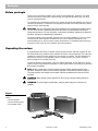
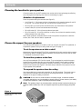
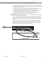
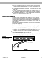
The Bose® 901® Series VI Direct/Reflecting® Speaker
System
Owner’s Guide
November 21, 2001
AM195438_03_V.pdf
Safety Information
English
WARNING: To reduce the risk of fire or electric shock, do not expose the 901® active
equalizer to rain or moisture.
CAUTION
CAUTION
AV I S
RISK OF ELECTRICAL SHOCK
DO NOT OPEN
RISQUE DE CHOC ÉLECTRIQUE
NE PAS OUVRIR
CAUTION: TO REDUCE THE RISK OF ELECTRIC SHOCK,
DO NOT REMOVE COVER (OR BACK).
NO USER-SERVICABLE PARTS INSIDE.
REFER SERVICING TO QUALIFIED PERSONNEL.
ATTENTION : POUR RÉDUIRE LE RISQUE DE DÉCHARGE
ÉLECTRIQUE, NE RETIREZ PAS LE COUVERCLE (OU
L’ARRIÈRE). IL NE SE TROUVE ÀL’INTÉRIEURAUCUNE
PIÈCE POUVANT ÊTRE RÉPARÉE PARL’USAGER.
S’ADRESSER À UN RÉPARATEUR COMPÉTENT.
These CAUTION marks are located on the bottom of your 901 active equalizer:
The lightning flash with arrowhead symbol, within an equilateral triangle, is intended to alert
the user to the presence of uninsulated dangerous voltage within the system enclosure that
may be of sufficient magnitude to constitute a risk of electric shock.
The exclamation point within an equilateral triangle, as marked on the system, is intended to
alert the user to the presence of important operating and maintenance instructions in this
owner’s guide.
CAUTION: To prevent electric shock, match wide blade of plug to wide slot, insert fully.
Additional safety information
See the additional instructions on the Important Safety Information page enclosed with this
owner’s guide.
Please read this owner’s guide
Please take the time to follow this owner’s guide carefully. It will help you set up and operate
your system properly, and enjoy all of its advanced features. Save your owner’s guide for
future reference.
For your records
Serial numbers are located on the bottom panel of each 901 speaker and on the back of the
active equalizer.
Loudspeaker Serial Numbers: ____________________________________________________
Active equalizer Serial Number: __________________________________________________
Dealer name: __________________________________________________________________
Dealer phone: _______________________ Purchase date: ___________________________
We suggest you keep your sales slip and warranty card together with this owner’s guide.
2
November 21, 2001
AM195438_03_V.pdf
Contents
Where to find…
Contents
Where to find… ............................................................................................................. 3
Warranty period ............................................................................................................ 3
Customer service .......................................................................................................... 3
Setting Up
Before you begin ........................................................................................................... 4
Unpacking the cartons .................................................................................................. 4
System compatibility .................................................................................................... 5
Choose the support for your speakers ......................................................................... 6
Choosing the location for your speakers ...................................................................... 6
Speaker connections .................................................................................................... 8
Equalizer connections ................................................................................................... 9
Testing the speakers and equalizer ............................................................................ 12
Using other equipment ............................................................................................... 13
Using your 901® Series VI speaker system
Playing your speakers ................................................................................................. 14
Adjusting the sound .................................................................................................... 15
Equalizer compatibility ................................................................................................ 16
Connecting additional speakers ................................................................................. 16
Maintaining Your 901 speaker system
Cleaning your speakers .............................................................................................. 17
Troubleshooting .......................................................................................................... 17
Product Information
Technical information .................................................................................................. 18
Accessories ................................................................................................................. 18
Bose Corporation ..................................................................................... inside back cover
Warranty period
The Bose® 901 speakers and active equalizer are covered by a limited 5-year transferable
warranty. Details of the warranty are provided on the warranty card that came with your
system. Please fill out the information section on the card and mail it to Bose Corporation.
Customer service
For additional help in solving problems, contact Bose customer service. See the inside back
cover for Bose customer service offices and phone numbers.
A free booklet is available: Guide to Optional System Connections for Bose 901® Direct/
Reflecting® Speaker Systems. Ask for part number 149393.
AM195438_03_V.pdf
November 21, 2001
3
Setting Up
English
Before you begin
Thank you for purchasing the Bose® 901® Series VI Direct/Reflecting® speakers. They represent the best in Bose Corporation speaker design and engineering and will give you many
years of listening pleasure.
The installation and operating principles of this system are significantly different from those of
conventional speakers. To obtain the best possible performance and avoid problems, please
take the time to read this guide.
CAUTION: You must have a Bose 901 active equalizer for a complete 901 speaker system.
The use of 901 Series VI speakers without the 901 Series VI active equalizer will result in
improper performance. The use of graphic or parametric equalizers, instead of the Bose 901
equalizer, will result in unsatisfactory performance.
Conventional graphic and parametric equalizers may be used in addition to, but not in place
of the Bose 901 active equalizer. However, the use of such additional equalizers is not
recommended since it will not improve system performance. For adequate performance you
must use the 901 Series VI active equalizer with these speakers.
Unpacking the cartons
A complete Bose 901 Series VI speaker system consists of three matched components: two
901 Direct/Reflecting® speakers and a separate 901 Series VI active equalizer. Two cables are
included to connect the active equalizer to your receiver or amplifier. The 901 speakers and
equalizer are packed in three separate cartons. Carefully unpack your system, saving all
packing materials for possible future use.
Inspect the speakers and equalizer. If any part appears damaged, do not attempt to use the
system. Repack the speakers and equalizer in their original cartons and notify your authorized
Bose dealer immediately.
Note: Now is a good time to record the serial numbers of each speaker and the active
equalizer. Please write them on your warranty card and in the spaces provided on page 2.
The serial numbers are located on the bottom of the 901 speakers and on the back of the
equalizer.
WARNING: Each speaker carton weighs over 35 lb (16 kg). Use good lifting practice to
avoid injury.
WARNING: To avoid danger of suffocation, keep the plastic bags out of the reach of
children.
Figure 1
What comes in the three
cartons:
• Two 901 speakers
• One 901 active equalizer
• Two equalizer cables
4
November 21, 2001
AM195438_03_V.pdf
Setting Up
System Compatibility
Bose® 901® Series VI speakers and Series VI active equalizer work with your stereo
components to produce a superb music system. The active equalizer is an integral part of
the system and may be connected in a variety of ways, depending on the components
you have. The two most common methods are described in this guide. Using different
components may require different connection methods. More information is available by
calling Bose Corporation. Ask for the free booklet, Guide to Optional System Connections
for Bose 901 Direct/Reflecting® Speaker Systems, part number 149393.
Your 901 speakers are designed to work compatibly with receivers or amplifiers rated from
10 to 450 watts per channel. In this guide, the term receiver is used to refer to an
integrated preamplifier and power amplifier (which may also contain an AM/FM tuner). The
term amplifier is used to describe configurations involving separate preamplifier and
amplifier components.
Most receivers have a TAPE MONITOR connection. The 901 active equalizer is most
commonly connected to the tape monitor connections on the receiver. If you plan to
connect a tape recorder, use the set of inputs and outputs located on the back of the 901
active equalizer marked TAPE RECORDER CONNECTIONS.
If you have recently purchased a home theater receiver, you may be considering using
your 901 speakers for the front channels. Your home theater receiver must have
accessible PRE AMP OUT/MAIN AMP IN connections for the front channels if you are to
use your 901 speakers in this way. These may also be called the ADAPTER or SIGNAL
PROCESSOR connections.
Installation steps
Follow these steps, in the order below, to install your 901 Series VI speaker system.
1. Choose the best locations and support for the 901 speakers (page 6).
2. Connect the speakers to the amplifier or receiver (page 8).
3. Connect the 901 active equalizer to the amplifier or receiver using either the TAPE
MONITOR or PRE AMP OUT/MAIN AMP IN connections (page 9).
4. Test the system to see that the audio signal is correctly processed by the active
equalizer (page 12).
AM195438_03_V.pdf
November 21, 2001
5
English
Setting Up
Choosing the location for your speakers
Choose locations for your 901® speakers that use the walls to best advantage by reflecting
sound throughout the listening room. Refer to the drawing on page 7.
Guidelines for placement
Place the speakers along the same wall (see Figure 3):
• 4 to 12 feet (1.2 – 3.6 m) apart, with the V-shaped rear of the speaker between 8 and 18
inches (20 – 45 cm) from the rear wall. Do not aim the V toward a corner.
• 18 inches (45 cm) of clear space around the sides, top, and bottom of the speakers.
• at least 2 feet (60 cm) from sound-absorbent furnishings.
• 18 to 48 inches (45 – 120 cm) from the side and rear walls.
• 18 to 36 inches (45 – 91 cm) from the floor or ceiling. Do not place the speakers exactly
halfway between floor and ceiling.
Within these guidelines, remember that the closer the speakers are placed to a reflective
surface, like a wall, the more bass is reproduced.
Choose the support for your speakers
You may place 901 speakers on a table or shelf. You may also use Bose® floor pedestals, or
suspend the speakers from your ceiling. Refer to Figure 3 on page 7.
To set the speakers on a table or shelf
Although each speaker weighs 35 lb (16 kg), a suitable shelf or table must be able to support
140 lb (64 kg). Keep an adequate distance between the speakers and the rear wall as listed
in “Guidelines for placement” above.
To stand the speakers on the floor
Use only Bose pedestals (PS-6) as floor stands. They are designed to provide the proper
support and are available through your authorized Bose dealer. Please read the pedestal
attachment instructions before making any speaker connections. Four pilot holes on the
bottom of each speaker (see Figure 2, hole set A) are pre-drilled for the purpose of anchoring the speaker to the pedestal.
To suspend the speakers from the ceiling
Use these guidelines to ensure safe suspension of your 901 speakers. Three steel support
chains are recommended. We cannot specify the ceiling attachments. The type to use
depends on the type of building construction.
CAUTION: Do not mount on surfaces that are not sturdy enough, or that have hazards
concealed behind them, such as plumbing or electrical wire. If you are unsure of your ability
to install these speakers, contact a qualified professional installer.
Note: The speakers hang in an inverted position, with the terminal connections facing up.
Carefully rotate the Bose logo 180˚ (so it appears right side up) before hanging the speakers.
Figure 2
Pedestal (A) and ceiling mount
(B) pilot holes
B
A
A
A
B
6
B
A
November 21, 2001
AM195438_03_V.pdf
Setting Up
Hardware needed for ceiling suspension
• Screw hooks support the chains at the ceiling. They must have at least a #10 wood
thread with a shank diameter of at least 3⁄16 inch (4.5 mm). They should be long enough
to go through any plasterboard and still have at least one inch (25 mm) of thread left to
penetrate a wood beam. For a masonry ceiling: use only high-quality metal expansion
masonry anchors that fit the thread of the ceiling hooks.
• Chain: diameter should be at least 5⁄32 inch (0.135 in. or 4 mm).
• Screw eyes with S hooks attach chains to the speaker and must have at least a #10
wood thread with a shank diameter of at least 3⁄16 inch (4.5 mm) or larger.
• All hardware (screw hooks, chain, screw eyes, S hooks) must have a manufacturer’s
safe-load rating of 40 lb (18 kg) or more.
General notes on ceiling suspension
• Suspend the speakers 18 – 36 inches (45 – 91 cm) from the ceiling; do not mount them
flush to the ceiling.
• To ensure an accurate stereo image, the distance from the floor should be three to ten
feet (1 – 3.5 m). Be sure the speakers are no less than 18 inches (45 cm) from the floor.
Do not suspend the speakers exactly halfway between the floor and ceiling.
Note: If the speakers are more than 10 feet (3 m) from the floor, we suggest you lengthen
the chain supporting the rear of the speaker. By doing this you will allow the rear of the
speaker, housing eight of the nine drivers, to be angled slightly downward.
Step by step procedure for ceiling suspension
1. Ceiling: Anchor at least two screw hooks into a rigid structural ceiling support (beam,
joist, or masonry anchor). Drill pilot holes into wood using a 1⁄8 inch drill bit (3.7 mm), if
necessary.
2. Speaker: Use the three pre-drilled pilot holes (see Figure 2 - hole set B) on the bottom of
each speaker. Use a 1⁄8 inch drill bit (3.7 mm) to enlarge the pilot holes to accept the #10
thread screw eyes. Drill to a depth of 1⁄2 inch (12 mm) in the speaker cabinet. Do not drill
completely through the cabinet.
Note: Contact Bose® for more information on suspending speakers. See the inside back
cover for phone numbers. For details on your specific ceiling construction, consult a
qualified building contractor or professional installer.
Figure 3
Mounting guidelines
18 – 36" (45 – 91 cm)
4 – 12'
(1.2 – 3.6 m)
8 – 18"
18 – 48"
(45 – 120 cm)
–
(20 – 45 cm)
4 – 12'
(1.2 – 3.6 m)
18 – 48"
(45 – 120 cm)
18 – 36" (45 – 91 cm)
AM195438_03_V.pdf
November 21, 2001
7
English
Setting Up
Speaker connections
With your speakers in their chosen locations, connect them to the receiver.
Choosing the wire
It is important to use the right thickness of speaker wire. For distances of up to 30 feet (9 m),
18 gauge (.075 mm2) 2-conductor wire works well. For distances greater than 30 feet (9 m),
refer to the wire recommendations chart on page 18.
Note: To determine if this wire is suitable for use in a wall or under a floor, check your local
building codes. You may want to contact a qualified electrical installer for this information.
Preparing the speaker wires
Examine the speaker wire. Note that it is actually a pair of insulated wires that may be gently
pulled apart. The insulation around one wire is marked with a stripe, collar, rib, groove, or
printing. Use the marked wire as positive (+) and the unmarked wire as negative (-). These
wires correspond to the positive and negative terminals on the speaker and receiver.
Note: It may be difficult to distinguish wire markings. Inspect both wires carefully.
To prepare the ends of each wire:
1. Strip approximately 1/2 inch (12 mm) of insulation from both wires.
2. Twist the bare ends of each stranded wire, to prevent strands from touching across
terminals.
Connecting the speakers
CAUTION: Before making any connections, turn off your receiver and unplug it from the
AC (mains) power outlet. Not doing this may result in damage to your system.
Speaker terminals are located on the bottom of each speaker. Unscrew the knurled nut on
each terminal and remove one washer. Wrap one bare wire end around the terminal post.
Then, replace the metal washer on the screw post and screw the knurled nut firmly back on.
1. Connect one wire pair to the right speaker (the one on your right as you face it).
a. Attach the marked wire at one end to the positive (+) terminal.
b. Attach the plain wire at that end to the negative (-) terminal.
2. Connect the other ends of the same wire pair to the RIGHT SPEAKER OUTPUT of your
receiver.
a. Attach the marked wire to the positive (+) terminal.
b. Attach the plain wire to the negative (-) terminal.
3. Following the steps above, connect the second pair of wires to the left speaker and to the
LEFT SPEAKER OUTPUT on the receiver.
Note: If your receiver offers a choice of output impedances, use the terminal marked 8Ω or
8 ohms.
8
November 21, 2001
AM195438_03_V.pdf
Setting Up
Checking the speaker connections
Make sure the terminal knurled nut is tightened down firmly. Any gap between the wire and
terminal can cause heat build up. Check to be sure the wires are connected positive to
positive (+ to +) and negative to negative (- to -). Make sure no loose strands of wire touch
across terminals, which can cause short circuits.
Figure 4
Connecting the speakers to the
receiver
Receiver
L
+ –
R
+ –
Equalizer Connections
There are two options for connecting the equalizer. Your choice depends on the type of
receiver you own and whether you plan to use the system primarily for stereo or for home
theater enjoyment.
Stereo/non-home theater use
(tape monitor connections)
The Bose® 901® active equalizer connects directly to your receiver through the tape monitor
connection. If your receiver has more than one tape connection, use the second one (TAPE 2).
To connect a tape deck, use the additional set of inputs and outputs located on the back of
the 901 active equalizer marked TAPE RECORDER CONNECTIONS.
The TAPE MONITOR switch on the front of the receiver lets you switch the equalizer in and
out of the signal path. This is important when you want to play conventional, non-equalized
speakers or headphones attached to your receiver. See Using other equipment on page 13.
Note: If your receiver is designed for home theater use, it may not have a Tape Monitor
switch. If not, you must use a PRE AMP OUT/MAIN AMP IN connection. This may also be
called the ADAPTER or SIGNAL PROCESSOR connection. Refer to “Home theater use (PRE
AMP OUT/MAIN AMP IN)” on page 10 for instructions on how to connect for home theater
use.
1. Disconnect any external tape deck or signal processor connected to the tape monitor
connection.
2. Use the twin cable assemblies (with two connectors at each end) that are supplied with the
equalizer. Use the red connector for the right (R) channel connections and the other
connector for the left (L) channel connections.
AM195438_03_V.pdf
November 21, 2001
9
Setting Up
English
3. Connect one end of a cable to the AMPLIFIER INPUT jacks on the 901® active equalizer.
a. Insert the first connector firmly into the INPUT jack marked R.
b. Insert the second connector into the INPUT jack marked L.
4. Connect the other end of the cable to the OUT or RECORD jacks on your receiver. These
jacks may be marked TO INPUT, FROM INPUT, or REC.
a. Insert the first connector into the OUT or RECORD jack marked R.
b. Insert the second connector into the OUT or RECORD jack marked L.
5. Connect the second cable from the AMPLIFIER OUTPUT jacks on the 901 active equalizer
to the IN or TAPE jacks on your receiver. These jacks may be marked PLAY, TO OUTPUT,
FROM OUTPUT, or MONITOR.
6. Plug the power cord of the 901 active equalizer into one of the switched outlets on the
receiver so that it will be powered when the receiver is switched on.
Figure 5
Connecting to the tape monitor
connection
Home theater use
(PRE AMP OUT/MAIN AMP IN)
Use these instructions:
• for stereo-only operation if your receiver does not have a TAPE MONITOR connection.
• if you are using a surround sound receiver that has a section on the back marked PRE
AMP OUT/MAIN AMP IN. The jacks may be labeled ADAPTER or SIGNAL PROCESSOR.
Note: If your receiver does not have this PRE AMP OUT/MAIN AMP IN section, the 901
speakers will not be usable in your home theater system.
1. The PRE AMP OUT/MAIN AMP IN jacks on your receiver are usually connected by small
bars called horseshoe pins. Remove these pins. See Figure 6.
Figure 6
Removing horseshoe pins
MAIN
AMP
IN
PRE
AMP
OUT
L
L
R
R
Amplifier or Receiver
10
November 21, 2001
AM195438_03_V.pdf
Setting Up
2. Use the twin cable assemblies (with two connectors at each end) that are supplied with the
equalizer. Use one connector for the right (R) channel connections and the other connector
for the left (L) channel connections.
3. Connect the amplifier INPUT of the Bose® 901® active equalizer to the PRE AMP OUT jacks
of the receiver or amplifier. Connect right channel to right channel and left to left.
4. Connect the amplifier OUTPUT of the active equalizer to the MAIN AMP IN jacks on the
receiver or amplifier. Connect right channel to right channel and left to left.
5. Plug the power cord of the 901 active equalizer into one of the switched outlets on the
receiver so that it will be powered when the receiver is switched on.
Note: This connection method does not allow you to connect a tape deck directly to the active
equalizer. Connect it to the receiver instead.
Check to see that the 901 speakers are connected to the receiver MAIN or FRONT speaker
jacks. In this way the 901 active equalizer signals will reach only the 901 speakers – the front
channels of your home theater – and not any non-901 speakers used as center and surround
channels.
Call Bose Corporation for assistance with the connection of additional speakers or signal
processing equipment. Refer to the address information inside the back cover of this guide.
A free booklet is available (USA only): Guide to Optional System Connections for Bose 901
Direct/Reflecting® Speaker Systems. Ask for part number 149393.
Figure 7
Home theater receiver
connections
AM195438_03_V.pdf
November 21, 2001
11
English
Setting Up
Testing the speakers and equalizer
Choose the test method appropriate to your system:
To test the TAPE MONITOR connection
1. Turn off or disconnect any non-901 speakers or headphones that may be connected.
2. On the 901® active equalizer, press the MONITOR button IN to TAPE, and the BASS
button OUT to position 1.
3. Set the MID-BASS and MID-TREBLE sliders to center positions.
4. Press your receiver or amplifier TAPE or TAPE MONITOR button to the OUT or NORMAL
position so it is not selected.
5. Play music through your system. You should hear both speakers. Do not worry about the
sound quality at this point. The equalizer is not yet engaged. If there is no sound from
one or both speakers, check the receiver and speaker connections.
6. Move the receiver BALANCE control to the extreme left and then to the extreme right.
This tests the left and right channel orientation. If the channels are reversed, check the
connections.
To test the equalizer
You have now tested your speakers and their wiring. The following steps test the equalizer
and its wiring:
1. With the speakers playing, press the receiver TAPE or TAPE MONITOR button IN,
selecting the PLAY or MONITOR position. All sound should stop. If it does not, check
your equalizer wiring. Be sure the 901 active equalizer MONITOR button is set to
position 2 (TAPE).
2. Press the 901 active equalizer MONITOR button to SOURCE, position 1. The sound
should return with full, natural sound characteristics. The system is now ready for use. If
the sound does not return, and the equalizer power indicator is lit, the equalizer is
probably connected incorrectly. Review equalizer connections.
To test the PRE AMP OUT/MAIN AMP IN connection
If you have connected the 901 active equalizer to the PRE AMP OUT/MAIN AMP IN connection, follow these instructions to test the speakers, equalizer, and wiring before connecting any other equipment to your system.
1. Turn off or disconnect any non-901 speakers or headphones that may be connected. If
your system has a speaker selector switch, set it so that only the 901 speakers are
connected to your power amplifier.
2. On the 901 active equalizer, press the MONITOR button OUT to SOURCE, and the
BASS button OUT to position 1.
3. Set the MID-BASS and MID-TREBLE sliders to center positions.
4. Play music through your system. You should hear both speakers. If there is no sound
from one or both speakers, check to see that the power indicator on the equalizer is lit,
then check the receiver and speaker connections.
12
November 21, 2001
AM195438_03_V.pdf
Setting Up
5. Move the receiver BALANCE control to the extreme left and then to the extreme right.
This tests the left and right channel orientation. If the channels are reversed, check the
connections.
6. Turn off the receiver and temporarily unplug the 901® active equalizer from its AC (mains)
power outlet.
7. Turn your receiver back on. You should not hear any music through the system. If you
do, the equalizer is probably connected incorrectly. Check the equalizer connections.
8. Turn off the receiver before restoring AC power to the 901 equalizer. Plug the equalizer
back in to its AC outlet. The system is now ready for use.
Using other equipment
You can use the Bose® 901 active equalizer TAPE CONNECTION jacks for a tape deck,
VCR audio connection, signal processors, or other components. This will be necessary if
your receiver has only one tape connection and you have connected the equalizer to it. If
you connected the equalizer to the receiver’s TAPE 2 connection, you can use TAPE 1 for
these components.
Before making any connections, turn off the receiver and components. Be sure the active
equalizer power indicator is off.
To add a tape deck or VCR:
1. Use cables with RCA connectors at each end. One color (usually red) is for right (R)
channel connections and the other connector is for left (L) channel connections.
2. Connect the TAPE RECORDER OUTPUT of the equalizer to the LINE IN/REC of the tape
deck. Connect right channel to right channel and left channel to left channel.
3. Connect the TAPE RECORDER INPUT of the equalizer to the LINE OUT/PLAY of the
tape deck. Connect right channel to right channel and left channel to left channel.
Note: To use an external signal processor, or to add a graphic equalizer, contact Bose for
more information. Refer to the inside back cover of this guide.
A free booklet is available (USA only): Guide to Optional System Connections for Bose®
901® Direct/Reflecting® Speaker Systems. Ask for part number 149393.
Figure 8
Connecting a tape deck to
the 901 active equalizer
AM195438_03_V.pdf
November 21, 2001
13
English
Using Your 901® Series VI Speaker System
Playing your speakers
Always use the 901® active equalizer when playing your 901 speakers. How you set the
equalizer depends on how it is connected to your receiver.
When connected to TAPE MONITOR
Press your receiver TAPE MONITOR button to the IN or MONITOR position. This switches
the equalizer into the system. Check periodically to be sure the TAPE MONITOR is engaged.
On some receivers the button may be labeled RECORD SELECT or RECORD OUT.
To play a tape deck connected to the equalizer, press the MONITOR button on the equalizer
IN (TAPE, position 2).
Return the MONITOR button to OUT (SOURCE, position 1) to listen to components other
than the tape deck (CD player, radio, etc.).
CAUTION: Do not use the active equalizer with conventional, non-equalized speakers or
headphones. This can produce unnatural sound, and can even damage some non-901
speakers. Before you play any non-901 speakers, be sure the receiver TAPE MONITOR
button is OFF (OUT or NORMAL).
You can play a tape deck through conventional, non-equalized speakers, even if your
receiver has only one tape monitor connection. Follow these steps to do this:
1. Connect the tape deck outputs to the AUX input jack on your receiver.
2. Leave the inputs of the tape deck connected to the TAPE OUTPUT jacks on the 901
active equalizer.
3. Press the receiver TAPE MONITOR to OFF (OUT or NORMAL). This allows you to record
disc and radio sources. You may also play any program source (including tape) with or
without 901 equalization.
Note: This arrangement works only with tape decks. Do not use it with any type of signal
processing device.
When connected to PRE AMP OUT/MAIN AMP IN
1. You must leave the MONITOR button on the 901 active equalizer OUT (SOURCE,
position 1) at all times.
2. Do not connect tape decks to the 901 active equalizer when it is connected to this
amplifier connection. Connect the tape deck to the receiver or amplifier TAPE MONITOR
connection or AUX inputs.
3. The power amplifier is always receiving the 901 active equalized signal. This signal can
damage conventional speakers and headphones. Therefore, do not connect conventional
speakers or headphones unless you have disconnected the 901 equalizer.
Do not connect tape decks or signal processing devices to the 901 active equalizer when it
is connected between the preamplifier and main amplifier.
14
November 21, 2001
AM195438_03_V.pdf
Using Your 901® Series VI Speaker System
Adjusting the sound
Adjust the sound using the MID-TREBLE and MID-BASS sliders and BASS control on the
901® active equalizer. Use the tone controls on your receiver only after the MID-TREBLE and
MID-BASS sliders have been set according to the procedures below.
Using the MID-TREBLE and MID-BASS sliders
These controls let you make adjustments to compensate for the effects of speaker location,
room acoustics, and program quality.
1. Select a familiar musical piece.
2. Set your receiver tone controls to the center (flat) position. If it has a loudness compensation control (marked LOUD or LOUDNESS), set it to the OFF or OUT position.
3. Set the MID-TREBLE slider on the equalizer to its center position.
4. Play the selected music through the 901 speakers at normal volume. Move the MID-BASS
slider back and forth several times and listen to the effect. You should hear a significant
change in the fullness of the sound. If you do not, the active equalizer may not be engaged. Refer to Playing your speakers on page 14.
5. When you are familiar with the effect of the MID-BASS slider, set it to the extreme left.
Start the musical passage again and slowly advance the MID-BASS slider to the right until
the sound is rich and full, without excessive heaviness.
6. Replay the musical passage, this time moving the MID-TREBLE slider back and forth to
become familiar with its effect. You should hear a significant change in clarity of the
sound.
7. Set the MID-TREBLE slider to the extreme left and play the passage again. Slowly
advance the MID-TREBLE slider to the right until the sound is clear and detailed without
excessive shrillness.
Using the BASS control
The Bass control provides an alternate bass equalization. It is not a bass enhancement
switch, and it is not intended to boost the bass output of the speakers.
Press the BASS control IN (to position 2) to engage an alternate form of equalization that
changes the way the speakers handle low-frequency information. For example, you may
prefer pipe organ music with the alternate equalization. The control can also be useful in
eliminating feedback or rumble from a turntable.
AM195438_03_V.pdf
November 21, 2001
15
English
Using Your 901® Series VI Speaker System
Equalizer compatibility
The Bose® 901® Series VI active equalizer is designed for specific use with
Bose 901 Series VI speakers. It may also be used with 901 Series V speakers.
WARNING: Bose 901 Series I, II, III, or IV speakers require a substantially
different equalization. The 901 Series VI active equalizer must not be used
with Series I – IV speakers. For additional information on the active equalizer,
please contact Bose Service.
Connecting additional speakers
The type of speakers and how you will use them determines how many
amplifiers and 901 active equalizers you will need.
To run other non-901 speakers simultaneously requires the addition of a
second amplifier. To use other speakers simultaneously with the 901 speakers
requires the ability to isolate the 901 active equalizer signal so that it affects
only the 901 speakers.
Adding 901 speakers
You need just one 901 Series VI active equalizer to use a second pair of 901
Series VI speakers connected to a single receiver or amplifier. Connect the
additional speakers to the additional speaker output jacks on the receiver or
amplifier.
To use extra 901 speakers in a four channel or time-delay music system, you
will need a separate 901 active equalizer for each pair of speakers.
Adding conventional speakers
You need a separate power amplifier to play conventional speakers at the
same time as 901 speakers. Connect the 901 active equalizer to the amplifier
that drives the 901 speakers only.
CAUTION: Make sure the conventional speakers do not receive signals
from the 901 active equalizer.
Call Bose Corporation for assistance with the connection of additional
speakers or signal processing equipment. Refer to the address information on
the inside back cover of this guide.
A free booklet is available (USA only): Guide to Optional System Connections
for Bose 901 Direct/Reflecting® Speaker Systems. Ask for part number
149393.
16
November 21, 2001
AM195438_03_V.pdf
Maintaining Your 901®Series VI Speaker System
Cleaning your speakers
If your 901® speakers have a painted surface, clean with a soft damp cloth. If necessary, use
a mild detergent such as dish soap. If the speakers have a wood veneer finish, clean them
with wood furniture polish. You may vacuum the speaker grille panels carefully, if necessary.
Do not use any sprays near the system. Do not use any solvents, chemicals, or cleaning
solutions containing alcohol, ammonia, or abrasives. Do not allow liquids to spill into any
openings.
Troubleshooting
If you have a problem with your 901 Series VI speakers or 901 active equalizer, turn off the
receiver or amplifier before you proceed. Then check all the connections between the
speakers, receiver, and active equalizer. Correct any wiring problems before you follow the
guidelines below. Problems are more likely to originate with equipment other than speakers,
so you may also want to refer to your receiver or other component owner’s guides.
Problem
What to do
One speaker sounds
defective, or does not play
• Do not switch the wires; this could damage a speaker. Turn off the amplifier and disconnect
the defective speaker wire at the amplifier. Reconnect it to the other channel. If the speaker
now plays correctly, the problem is not in the speaker or wiring.
Neither speaker plays
• Connect the speakers to another receiver or amplifier that is known to be operating
properly. If the speakers now play correctly, the problem is not in the speakers.
Note that the tonal balance of the 901 speakers will be incorrect if the 901 active equalizer
is not being used with this second receiver or amplifier.
The high and low
frequencies seem weak
• Check to be certain that the 901 active equalizer is in the circuit. Review the Playing
your speakers section of this guide on page 14.
You hear distortion
at high volume levels
• Try turning down the volume. If the distortion goes away you may be using an insufficiently
powered receiver or amplifier.
The trouble seems to be in
the 901 active equalizer
• Bypass the equalizer to see if the system operates properly without it. (Speakers will not
have any highs or lows.) Check to see that all connections are correct and that none of
the cables is defective.
Trouble persists in the
speakers or equalizer
• Contact your authorized Bose® dealer to verify any defects and arrange for service by
a factory authorized agency or by the Bose factory. Bose Corporation will make every
effort to remedy any problem within the terms of the warranty.
AM195438_03_V.pdf
November 21, 2001
17
English
Product Information
Technical information
Bose® 901® Series VI Direct/Reflecting® Loudspeakers
901 Series VI active equalizer
Transducer complement
Input Impedance
Nine (9) 41/2" (11.4 cm) full-range Helical
Voice Coil drivers in each cabinet
47 k ohms (47 kΩ)
Energy dispersion
1 k ohm
89% by reflection
11% by direct radiation
Usable dynamic range
Output Impedance
106 dB @ 35 Hz
Enclosure
14-element Acoustic Matrix™ enclosure
with three reactive air columns
Noise (A-weighted)
Nominal impedance
Distortion
8Ω (ohms)
Less than 0.09% THD at 1 kHz, 1 V input
Amplifier compatibility
Compensation controls
Compatible with amplifiers/receivers rated
from 10 - 450 watts RMS.
Rated 250 watts IEC
Mid-Bass, ±6 dB @ 225 Hz
Mid-Treble, ±6 dB @ 3 kHz
Recommended fusing
Series connected 3A quick-acting fuse
Buss AGC-3, Littelfuse 312-003, or
equivalent
Cabinet
Greater than 90 dB below 1 volt
Bass Switch
– 6 dB @ 35 Hz
Power Requirements
120V ~ 50/60Hz, 3.5W
220-240V ~ 50/60Hz 3.5W
100V ~ 50/60Hz 3.5W
Oil-rubbed hardwood veneer with
walnut finish
Black vinyl veneer
Cabinet
Dimensions
Dimensions
21"W x 125/8"H x 13"D
(53.3 x 32.0 x 33.0 cm)
13"W x 23/4"H x 5"D
(33.0 x 7.0 x 12.7 cm)
Weight
Weight
35 lb. (16 kg) per enclosure
3.4 lb (1.5 kg)
Black anodized aluminum
Wire recommendations
Gauge
18 (0.75 mm2)
16 (1.5 mm2)
14 (2.0 mm2)
Length
30 ft (9 m) maximum
45 ft (14 m) maximum
70 ft (21 m) maximum
Accessories
To find out about PS-6 floor pedestals, contact your Bose dealer. Or call Bose directly (see
inside back cover for phone numbers).
18
November 21, 2001
AM195438_03_V.pdf
AM195438_03_V.pdf
November 21, 2001
19
Bose® Corporation
USA
Bose Corporation, The Mountain
Framingham, MA 01701-9168
1-800-367-4008
Phone hours - ET (eastern time):
Weekdays 8:30 a.m. to 8 p.m.
Saturdays 9 a.m. to 3 p.m.
Canada
Bose Ltd., 1-35 East Beaver Creek Road
Richmond Hill, Ontario L4B 1B3
1-800-465-2673
Phone hours - ET (eastern time):
Weekdays 9 a.m. to 5 p.m.
European Office
Bose Products B.V., Nijverheidstraat 8
1135 GE Edam, Nederland
TEL 0299-390111
FAX 0299-390114
Australia
Bose Pty Limited, 1 Sorrell Street
Parramatta NSW, 2150
TEL 02 9204-6111
FAX 02 9204-6122
Belgique/België
Bose N.V., Limesweg 2, B-3700 Tongeren
TEL 012-390800
FAX 012-390840
Danmark
Bose A/S, Industrivej 7, 2605 Brøndby
TEL 4343-7777
FAX 4343-7818
Deutschland
Bose GmbH, Max-Planck-Straße 36d
D-61381 Friedrichsdorf
TEL 06172-71040
FAX 06172-710419
France
Bose S.A., 6, rue Saint Vincent
78100 Saint Germain en Laye
TEL 01-30616363
FAX 01-30614105
India
Bose Corporation India Private Limited
W-16, Greater Kailash-II
New Delhi 110 048
TEL (011) 648 4462 FAX (011) 648 4463
Ireland
Bose Corporation
Carrickmacross, Co Monaghan
TEL (042) 9661988
FAX (042) 9661998
Italia
Bose S.p.A., Via della Magliana 876
00148 Roma
www.bose.iT
TEL 06-65670802
FAX 06-65680167
Japan
Bose K.K., Shibuya YT Building
28-3 Maruyama-cho
Shibuya-ku, Tokyo 150
TEL 3-5489-0955
FAX 3-5489-0592
Nederland
Bose B.V., Nijverheidstraat 8
1135 GE Edam
TEL 0299-390111
FAX 0299-390109
Norge
Bose A/S, Solheimsgate 11
N-2001, Lillestrøm
TEL 63-817380
FAX 63-810819
Österreich
Bose Ges.m.b.H., Vienna Business Park
Wienerbergstrasse 7 (10.OG)
A-1100 Vienna
TEL 01-60404340
FAX 01-604043423
Schweiz
Bose AG, Rünenbergerstrasse 13
4460-Gelterkinden
TEL 061-9815544
FAX 061-9815502
Sverige
Bose A/S, Johannefredsgatan 4
S-43153 Mölndal
TEL 31-878850
FAX 31-274891
United Kingdom
Bose Limited
1 Ambley Green
Gillingham Business Park
Gillingham, Kent ME8 ONJ
TEL 0870-741-4500 FAX 0870-741-4545
From other locations
Bose Customer Service, 1 New York Ave.
Framingham, MA 01701-9168 USA
TEL (508) 766-1900 FAX (508) 766-1919
World Wide Web
www.bose.com
©2000 Bose Corporation, The Mountain,
Framingham, MA 01701-9168 USA
195438 AM Rev.03 JN20413