1
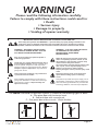
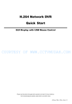
Cobra
®
Overhead Garage Door Opener
Installation Manual
Page 1
Page 2
WARNING!
Please read the following information carefully.
Failure to comply with these instructions could result in:
• Death
• Serious Injury
• Damage to property
• Voiding of opener warranty
IMPORTANT SAFETY INSTRUCTIONS FOR INSTALLATION AND USE
These safety alert symbols mean WARNING – a personal safety or property damage instruction. This
garage door opener is designed and tested to offer reasonable safe service provided it is installed,
operated, maintained and tested in strict accordance with the instructions contained in this manual.
WARNING – INCORRECT INSTALLATION
CAN LEAD TO SEVERE INJURY. FOLLOW
ALL INSTALLATION INSTRUCTIONS.
Door must not extend over public footpaths or
roads during operation.
Install only on a properly balanced garage door in
good operating condition. Sticking or binding doors
must be repaired. Garage doors and components
attached to them are under extreme tension. Do not
attempt to repair or adjust them. Get professional
garage door service
WARNING – IT IS VITAL FOR THE SAFETY
OF PERSONS TO FOLLOW ALL
INSTRUCTIONS. SAVE THESE
INSTRUCTIONS!
Watch the moving door and keep people away
until it is completely opened or closed. Do not
allow children to play with door controls. Keep
remote controls away from children.
Use caution when operating manual release if the
door is open, since it may fall rapidly if out of
balance or if springs are weak or broken.
Property damage or serious personal injury could
result.
This unit must be installed in a dry position that
is protected from the weather.
Disconnect electric power to the garage door
opener before making repairs or removing
covers.
After installation and adjustment, ensure that your
garage door reverses on contact with a 40mm high
object placed on the floor. Repeat monthly and
adjust as necessary.
This product is provided with a power supply cord of
special design. If damaged, it must be replaced by a
cord of the same type obtained from your Automatic
Technology distributor, and must be specially fitted.
The Cobra® Overhead Garage Door Opener is suitable for the following types of doors:
A - One piece door with horizontal track
B - Sectional door with curved track
C - One piece door without track / J-Style tilt door
A
B
C
Page 3
Thank you!
Welcome to the installation and instruction manual for your new
Automatic Technology Cobra overhead garage door opener.
Created and designed by the latest technological advances, and using the best
possible components in the most stringent manufacturing processes athis opener
will provide many years of reliable, faithful and safe service to you and your family.
TABLE OF CONTENTS
PRODUCT FEATURES............................................................................................. 5
OPERATING CONTROLS........................................................................................ 6 - 8
INSTALLATION....................................................................................................... 9 - 16
DOOR TRAVEL LIMITS............................................................................................ 17
SAFETY FORCE MARGIN....................................................................................... 18
CODING/DELETING TRANSMITTERS.................................................................... 19 - 21
FIITING PE BEAMS..................................................................................................21
PROGRAMMING OPERATING MODES & COURTESY LIGHT.............................. 22 - 24
FACTORY DEfAULT SETTINGS & SPECIFICATIONS............................................. 25
WARRANTY............................................................................................................. 27
Page 4
PRODUCT FEATURES
OPERATION
To open or close the door simply press the hand held transmitter, the wall mounted transmitter, or optional wall
switch. During an open or close cycle the door can be stopped by pressing the button while the door is in motion.
The next actuation will move the door in the opposite direction.
SecruaCode® HOPPING CODE TECHNOLOGY
Every time a SecuraCode® transmitter is used, it generates a new access code from 4.29 billion possibilities. This random process makes it is near impossile for unwanted operation of your Cobra® Overhead Garage Door Opener.
AUTO CALCULATE THE LIMITS AND SAFETY FORCE
During installation, after setting the open and close positions with your SecuraCode® transmitter, the Cobra® Overhead Garage Door Opener automatcially measures the force required to move your door. These travel limits and the
safety force will be stored in the memory. Also, the current door position will be remembered during a power failure
or if the door is moved manually.
SAFETY OBSTRUCTION SYSTEM
Should the door contact an obstacle or be restricted in any manner while closing it will automatically reverse. This
level of safety force is automatically calculated when the Cobra® Overhead Garage Door Opener is initially installed.
The door will also stop if restricted whilst opening. The Safety Obstruction Force should be checked at least once a
month.
AUTO COURTESY LIGHT
A SecuraCode® transmitter button can be programmed to independantly operate the courtesy light. The courtesy
light also turns on with any door operation, shutting off after an adjustable specified time.
VACATION MODE
A SecuraCode® transmitter can be programmed to lock and unlock all other transmitters programmed into the
openers’ memory. This will prevent any transmitter other than the programmed one from opening the door, stopping unauthorised access while you are away.
PET (PEDESTRIAN) MODE
A SecuraCode® transmitter button can be programmed to partially open the door for a pet to enter or exit the
garage at any time. The door opening position is also programmable so that the door can be opened to a suitable
height for pedestrian access.
AUTO-CLOSE
The Cobra® Overhead Garage Door Opener can be programmed to automatically close after the door is fully
opened. The auto close time is adjustable. The Photo Electric Beam must be installed to prevent the door closing
when an obstruction may still be present, thus causing personal injury or damage to property.
PHOTO ELECTRIC BEAM
The Cobra® Overhead Garage Door Opener has an input for a Photo Electric Beam to be connected for extra safety
protection as well as ustilisation of the auto-close mode.
ALARM / STATUS OUTPUT
An external alarm may be toggled on/off by pressing the SecuraCode® transmitter button. If the alarm function is
not used the alarm output can function as a Door Status output.
MANUAL OPERATION
If the power to the Cobra® Overhead Garage Door Opener is disrupted for any reason, the door can be disengaged
by pulling down on the string handle on an angle towards the door. This will allow you to manually open or close the
door. To re-engage the opener pulls the string handle away from the door.
STANDBY (Power Save) MODE
If the Cobra® Overhead Garage Door Opener is left for five minutes without any button presses, the unit will enter
standby mode. The decimal point indicator on the display will turn on. The unit will continue usual operation. When
the next button press occurs the display will again turn on.
Page 5
OPERATING CONTROLS
6
7
COM
OSC
PE
24V
COM
P2
P1
ALM
LT
LCK
.
/($51
1
2
3
,167$//
4
5
1. ENGAGE DISENGAGEMENT HANDLE, EASY ACCESS TRANSMITTER
The “manual release” engage/disengagement handle has a wireless transmitter within its housing. If the button is
pressed it will open, stop or close the garage door.
2 ENGAGE/DISENGAGEMENT CORD
When pulled down towards the door this will disengage the door to the manual mode, particularly when there is a
power failure. Pulling down away from the door and releasing will engage the door to the auto mode. The length
of the cord is adjustable.
3. LEARN BUTTON
Pressing the LEARN button momentarily scrolls through the modes in the following order. The appropriate letter
will be shown on the display
Handheld. Program in a transmitter button to operate the Door.
2) Courtesy Light. Program in a transmitter button to operate the light.
3) Alarm. Program in a transmitter button to pulse the Alarm output.
4) Pet. Program in a transmitter button to operate the Pet position.
5) Locked. Program in a transmitter to operate the Vacation mode.
6) Erase. Erase transmitter (function) from memory.
7) Factory settings. Keep all transmitter codes and set all other settings to defaults.
1)
Page 6
OPERATING CONTROLS
4. DISPLAY
General Display Codes
dcc ro7
Flashes on the display once the opener powers up (dc opener chain drive,
firmware revision o7)
r
Reset limits, Door has not been set to its limits
P
Flashes on the display, door is stationary and in Pet Mode
O
Flashes on the display, door is stationary and not at the close, open or pet posi
tions
O
Door is currently Open
C
Door is currently Closed
E
On the last operation an obstruction was detected
t
Will only flash briefly before going to E. Indicates Hall Effect sensor timeout
d
Will only flash briefly before going to E. Indicates standard door obstruction
S
Indicates the door is probably closed but being obstructed, E.g. snow around the
door
b
The opto beam is indicating an obstruction.
H
The door has been detected as too heavy
LoC
Flashes on the display, door is on vacation lock mode.
EOS
Flashes on the display, door was forced open via BMS. Power must be removed to
reset this.
o
Flashes on the display, the close position has been set, it is ready to move the
door to open position.
.
Unit is in power save mode
5. INSTALL BUTTON
Pressing the INSTALL button momentarily scrolls through the modes in the following order.
The appropriate letter will be shown on the display.
1) Limits. Set the Limits.
2) Force. Set the Force Margin.
3) Pet. Set the Pet mode
4) Autoclose. Set the Autoclose Time.
5) Courtesy Time. Set the Courtesy Light Time.
Pressing the LEARN button at any time or waiting for 10 seconds exits this menu.
6. TERMINAL P1
Alarm/Status(ALM)
Pressing the transmitter button associated with the Alarm function, the alarm terminal will
enable the output to pulse for a preset period so that an external alarm may be toggled on/off.
If there are no transmitter buttons memorised for the security alarm this output will function as
a door Status output. When the door is open or partially open the output will be on. When the
door is closed the output will be off. When the door is moving the output will toggle at the rate
of 2Hz.
Page 7
OPERATING CONTROLS (continued)
6. TERMINAL P1 (continued)
Light (LT)
A 24V DC relay of the appropriate contact voltage can be connected to the light terminal (LT)
and 24V terminal to control external lights by the transmitter button associated with the courtesy light or with any door operation.
Lock (LCK)
When a button programmed for vacation mode is pressed, the door will not respond to any
other transmitters after the door reaches its close position until this mode is reversed.
If there is no transmitter button programmed for vacation mode, then the terminal will function
as a BMS input. When the door reaches its close position, the door will be forced to open and
then opener will freeze until it is powered up again
7. TERMINAL P1
Photo Electric Beam Input (PE)
A link between PE and COM has to be removed when connecting a Photo Electric Beam.
NOTE: The link must not be removed otherwise the opener will not function correctly. Remove only when a PE beam is to be connected.
24V Power Supply (24V)
24V output supplies 24V DC 20% ripple at 60mA to power an external receiver or electronic
device, etc.
Open/Stop/Close Input (OSC)
OSC INPUT is used for the connection of a wired switch (momentary contact). This switch
can then be used to open, stop or close the door. Wire the normally open momentary
contact switch to the OSC and COM terminals.
Page 8
INSTALLATION
Tools you may need
1
2
STEP ONE:
PLEASE NOTE - Ensure the bracket is mounted on door at a position of high strength as large forces can be
transmitted to the door at this location.
Tilt Door
Mount Door Bracket flush to top of door at centre position (see fig 1a).
Sectional Door
Mount Door Bracket about one-third of the way down the top door panel at centre position (see fig 1b).
7RS SDQHO
'RRU EUDFNHW
IOXVK ZLWK WRS
RI GRRU
6HOIGULOOLQJ
ILQH WKUHDG
WHF VFUHZV
)LJ D
7LOW GRRU IL[LQJ
6HOIGULOOLQJ
ILQH WKUHDG
WHF VFUHZV
'RRU EUDFNHW
UG GRZQ
)LJ E
6HFWLRQDO GRRU
IL[LQJ
Page 9
INSTALLATION (continued)
STEP TWO:
Determine the centre of the door and continue the vertical line through the header as in FIG 2
)LJ 'UDZ 9HUWLFDO &HQWUH /LQH
IURP 'RRU WR +HDGHU
+HDGHU
'RRU
STEP THREE:
Lift the door and find the highest point to which the top of the door reaches. Using an appropriate straight edge
and level, transfer the height to the header.
STEP FOUR:
Fix the Header Bracket to the Header so that the bottom of the bracket is at least 10mm above the height found in
step 3 (see fig 3). Find a solid fixing point as significant forces act through the Header Bracket.
9HUWLFDO FHQWHU OLQH
+HDGHU %UDFNHW
[ 7HN 6FUHZV
PP
+LJK SRLQW RI GRRU
)LJ 3
STEP FIVE:
Assemble the chain idler wheel inside the idler housing as shown in Figs 4a, 4b & 4c.
&KDLQ LGOHU
ZKHHO
0 [ ORQJ
FDUULDJH EROW
,GOHU D[OH
)LJ F
,GOHU KRXVLQJ
)LJ D
&RPSRQHQW SDUWV
RI FKDLQ LGOHU DVVHPEO\
)LJ E
$VVHPEOHG
FRPSRQHQW SDUWV
Page 10
$VVHPEO\ YLHZHG
IURP XQGHUQHDWK
VKRZLQJ LGOHU D[OH
UHJLVWHUHG LQ NH\KROH
VORW
INSTALLATION (continued)
STEP SIX:
Lay the rail on the ground with channel side facing up. Insert the Traveller and Chain Idler assembly into the end
of the rail. Locate chain around the Chain Idler Wheel and through the Traveller as shown (see fig 5). Ensure chain
ends are located at a mid-rail position.
STEP SEVEN:
Connect the chain using the spool and joining links as shown in fig 6. Ensure chain is not twisted.
Page 11
INSTALLATION (continued)
STEP EIGHT:
Locate chain at Drive unit end onto drive unit sprocket. Keeping chain taut on sprocket, insert drive unit chassis
onto rail and slide forward until the chassis upright hits end of rail (see figs 7a & 7b).
STEP NINE:
Install Idler bracket inside door end of rail. Keeping door end of chain taut inside Idler Wheel, fit M8 nyloc nut as
shown in fig 8.
STEP TEN:
Tension the chain by tightening the M8 nyloc nut. The tension is correct when the center of the chain is clear of the
rail by 5mm. Check chain tension after initial installation and thereafter as required. The tension can be adjusted
after installation, but only while the chain is not moving.
IMPORTANT - DO NOT OVERTIGHTEN CHAIN
Page 12
INSTALLATION (continued)
STEP ELEVEN:
Determine a suitable method to support the drive unit from the ceiling depending of the direction of ceiling batons
or joists. Supplied in the box is the Hanger Bracket, (Fig. 9a).
The sides of the hanger can be cut along the pre-punched small holes and then folded to the required angle as
shown in Fig. 9b. The hanger can be secured on the end of chassis (as shown in Fig. 9a), or on top of the center of
the C rail using two 10x16 wafer Tek/YZC screws (not supplied) shown in Fig 9b
Perf angle can also be straight screwed onto the chassis for mounting the unit as shown in Fig 9c and Fig 9d.
STEP TWELVE:
Mark the top center of the door. Raise the door to the fully open position and transfer the mark directly up to the
ceiling. This will ensure when fixing the motor that the unit will pull centrally on the door throughout its range of
motion.
Failure to do so may result in damage to the motor or other mechanical components and fixtures.
Page 13
INSTALLATION (continued)
STEP THIRTEEN:
Place the drive unit on the garage floor with corrugated cardboard or old carpet underneath to prevent damage.
Lift up the assembled rail and motor unit. Slide the idler bracket over the header bracket tags. Pull the rail back
and down so the header bracket tags engage in the slots in the idler bracket as shown in Fig. 10. If required, rest
the motor end on a ladder.
Raise the motor end up and fix to the ceiling as in Fig 9a to Fig 9d, keeping the rail level. Once the motor end is
mounted, bend the header bracket tags slightly so the idler bracket can’t jump off, as shown in Fig. 11. For example, use pliers to bend the tags out a few millimetres.
STEP FOURTEEN
Attach release cord to the disengage lever, Fig 12b. To keep the traveller disengaged, pull down the cord on an
small angle towards the door. The lever will latch in the disengaged position as shown in Fig 12a. To re-engage the
traveller, pull the cord down on an angle away from the door, then release straight up as shown in Fig 12b.
2.
1.
Page 14
INSTALLATION (continued)
STEP FIFTEEN:
Ensure door is fully closed. Pull traveller and straight arm by hand until straight arm can be attached to Door bracket (Fig 13a). Use release cord to free Traveller if it engages with chain spool. A curved arm is added to straight arm
when the Door bracket is installed below the top of the door. (Fig 13b)
STEP SIXTEEN:
Ensure the entire unit is securely fixed in position. With traveller is attached, open and close the door manually to
test that the door runs correctly. Check there is clearance between the door and the opener.
Other C-Rail mount options for low headroom
1. The header bracket and C-Rail can be mounted as shown in Fig. 14 for low head room situation. The clevis pin
and spring clips are ordered separately
2.
The C-rail also can be surface mounted to a ceiling by screwing to the structural supports The heads of the
fitting screws (not supplied) should be low enough to allow passage of the slot on the centre traveller.
Page 15
INSTALLATION (continued)
STEP SEVENTEEN:
Pull door to half-open position until chain spool engages inside traveller. Plug in power to Drive Unit and switch on.
Remove lens by pushing it up from drive unit for programming the opener (Fig 15.).
R
)LJ 5
Page 16
PROGRAMMING - Door Travel Limits
SETTING DOOR TRAVEL LIMITS
FIG 16
To code transmitter for setting limits
1. Select Handheld Mode using the LEARN button on the unit.
Display shows (H)andheld (Fig. 16)
2. Within 10 seconds, momentarily press the required button on the
transmitter. The decimal point indicator on the display will
flash and then stay on.
3. Re-press the same button again momentarily, the decimal point
indicator will flash and then the display will show the memory
location number for that function ‘Hxx’. The location number
xx will be the first free location number in the memory.
.
/($51
,167$//
To set limits
4. Engage the traveller into the chain spool.
5. Select Limits mode using the INSTALL button on the unit. Display shows (L)imits (Fig 17).
NOTE: The door and traveller must be engaged with the chain spool. The close position MUST be set first, followed by the open position.
6. Press button 4 (Fig. 18), the door will start closing, release the button once you are 1 to 2 cm from your desired
closed limit position. Press button 3 (Fig. 18) for two seconds then release to change to Slow mode ( S will
flash on the display 3 times) .
7. Press button 4 briefly, each press will enable you to inch the door to your desired closed position (Press button 1
to adjust position if necessary).
8. Once you are happy with the close position press button 2 (Fig. 18) for two seconds, this action will store into
memory the closed limit position. The O will flash on the display. The opener is ready for setting the open
position.
9. Press button 1 (Fig. 18), the door will start opening, release the button once you are 1 to 2 cm from your desired
open limit position. Press button 3 for two seconds then release to change to Slow mode (S flashes on the
display 3 times).
10. Press button 1 briefly. Each press will enable you to inch the door to your desired open position (Press button
4 to adjust position if necessary).
IMPORTANT WARNING: Please be aware that the garage door will start closing automatically once step 11 is
performed. The door will also automatically re-open after fully closing with a small pause between the cycles.
11. Once you are happy with the open position, press button 2 for two seconds, to store in memory the open limit
position. The door will now automatically close and then fully open to calculate the safety obstruction
forces. Please be aware of the above warning.
Resetting Door Limits Positions
Follow Steps 4 to 11 to set new travel limit positions.
Please note that there is no need to re-code the transmitter used for setting the limit positions. After the limits
are set the transmitter will automatically reset to normal operation.
Go to next STEP and test the Safety Obstruction Force.
INCH OPEN
BUTTON 1
FIG 17
.
/($51
SET
BUTTON 2
INCH CLOSE
BUTTON 4
,167$//
FIG 18
SWITCH
BETWEEN
FAST AND
SLOW
INCHING
BUTTON 3
Page 17
PROGRAMMING - Safety Force Margin
Please take care when testing the Safety Obstruction Force. Excessive force may
cause DEATH, SERIOUS PERSONAL INJURY and/or PROPERTY DAMAGE can
result from failure to follow this warning.
TESTING CLOSE CYCLE
1. Open the door by pressing the transmitter button programmed for the door.
2. Place a length of timber approximately 50mm high on the floor directly under the door.
3. Press the transmitter button to close door. The door should strike the object and start to re-open.
TESTING OPEN CYCLE
1. Close the door by pressing the transmitter button programmed for the door.
2. Press again to open the door. When the door reaches half the opening distance, grab the bottom rail of the door
firmly, the door should stop.
If the door does not reverse readily when closing, or stop when opening, the force may be excessive and need
adjusting, refer to following.
IMPORTANT WARNING: If the door is closing and is unable to re-open when obstructed, discontinue use.
Do not use a door with faulty obstruction sensing. Repair fault and re-test before using.
ADJUSTING SAFETY OBSTRUCTION FORCE
NOTE: The Safety Obstruction Force is calculated automatically and set in memory on the Cobra® opener. It is
usually not necessary to adjust the Safety Obstruction Force. The only time the force may need to be increased is
due to environmental conditions, for example, windy or dusty areas, and areas with extreme temperature changes.
1. Select Force Margin Mode using the INSTALL button on the unit. Display shows (F)orce (FIG 19).
2. Using a pre-coded transmitter, press button 1 to increase the open pressure and button 4 to decrease the open
pressure (FIG 20). Similarly for close pressure use buttons 2 and 3 (FIG 20). The display will flash ‘F C x’ for
force close pressure and ‘F O x’ for force open pressure.
Where x is the force margin. The force margin can be
FIG 19
adjusted from minimum 0 to maximum 9.
3. To store the force margins press and hold the INSTALL button on
the unit until SE (Set) flashes on the display.
Note: A pre-coded transmitter implies that one of the buttons
of the remote is programmed to a function. This means
that the transmitter is stored in the Cobra® Overhead
Garage Door Opener’s memory.
.
/($51
Increase Open
Force
Button 1
,167$//
Increase Close
Force Button 2
Decrease Open
Force
Button 4
Decrease
Close
Force
Button3
FIG 2
Page 18
CODING TRANSMITTERS
PROGRAM A TRANSMITTER BUTTON TO OPERATE THE DOOR
1. Select Handheld Mode using the LEARN button on the unit.
Display shows (H)andheld (FIG 21).
2. Within 10 seconds, momentarily press the required button on the
transmitter. The decimal point indicator on the display will
flash and then stay on.
3. Re-press the same button again momentarily, the decimal point
indicator will flash and then the display will show the memory
location number for that function ‘H xx’. The location number
xx will be the first free handheld location number in the
memory.
4. Press the transmitter button to test if it operates the door.
FIG 21
.
/($51
,167$//
PROGRAM A TRANSMITTER TO OPERATE THE COURESTY LIGHT
1. Select Courtesy light mode using the LEARN button on the unit.
Display shows (C)ourtesy Light (FIG 22).
2 .Within 10 seconds, momentarily press the required button on the
transmitter. The decimal point indicator on the display will
flash and then stay on.
3. Re-press the same button again momentarily, the decimal point
indicator will flash and then the display will show the memory
location number for that function ‘C xx’. The location number
xx will be the first free light location number in the memory.
4. Press the transmitter button to test if it operates the light.
FIG 22
.
/($51
,167$//
PROGRAM A TRANSMITTER TO ACTIVATE PET MODE
1. Select PET mode using the LEARN button on the unit. Display
shows (P)ET (FIG 23).
2. Within 10 seconds, momentarily press the required button on the
transmitter. The decimal point indicator on the display will
flash and then stay on.
3. Re-press the same button again momentarily, the decimal point
indicator will flash and then the display will show the memory
location number for that function ‘P xx’. The location number
xx will be the first free PET location number in the memory.
4. Press the transmitter button to test if it operates the PET function.
FIG 23
.
/($51
,167$//
Page 19
CODING TRANSMITTERS (continued)
PROGRAM A TRANSMITTER TO ACTIVATE VACATION MODE
FIG 24
1. Select Vacation mode using the LEARN button on the unit.
Display shows (L)ocked (FIG 24).
2. Within 10 seconds, momentarily press the required button on the
transmitter. The decimal point indicator on the display will
flash and then stay on.
3. Re-press the same button again momentarily, the decimal point
indicator will flash and then the display will show the memory
location number for that function ‘L xx’. The location number
/($51
xx will be the first free vacation location number in the
memory.
4. To test, when door in close position press and hold the transmitter
button set for vacation function for 5 seconds. The display
will flash LC once the vacation mode is set. To reset vacation
function, press the same button for 5 seconds, the vacation mode will be unlocked.
.
,167$//
COPY PRE-CODED TRANSMITTER FUNCTIONS TO A NEW TRANSMITTER
Using this method you do not need to have access the LEARN
button on the unit. However, you do need a transmitter that is
pre-coded to the Cobra® Overhead Garage Door Opener.
Coding Hole
1. Using a small needle press the button through the Coding Hole
on a pre-coded transmitter (Fig 25) until the decimal point
illuminates and display shows (H)andheld (Fig 26).
2. Within 10 seconds press and hold the button on the new
transmitter for two seconds. ‘SEt’ (set) will flash on the
display.
3. All functions that were programmed into the pre-coded
transmitter are now copied onto the new transmitter.
4. Test the new transmitter.
PROGRAM A TRANSMITTER TO OPERATE THE ALARM
FUNCTION
1. Select Alarm mode using the LEARN button on the unit. Display
shows (A)larm (Fig 27).
2. Within 10 seconds, momentarily press the required button on the
transmitter. The decimal point indicator on the display will
flash and then stay on.
3. Re-press the same button again momentarily, the decimal point
indicator will flash and then the display will show the memory
location number for that function ‘Axx’. The location number
xx will be the first free location number in the memory.
4. Press the transmitter button to test if it operates the alarm.
FIG 25
FIG 26
.
/($51
,167$//
FIG 27
PLEASE NOTE: Note the Alarm output (ALM) shares its function
with the door status output. If there are transmitter codes
memorised for the security alarm this output will not function as
a door status output.
.
/($51
Page 20
,167$//
ERASING TRANSMITTERS / FITTING PE BEAMS
ERASE TRANSMITTER FROM MEMORY
1. Select Erase mode using the LEARN button on the unit. Display
shows (E)rase (Fig 28).
2. Press and hold a button on the required transmitter for 2 seconds
until the decimal point stays on.
3. Release transmitter button until the decimal point turns off, then
press the transmitter button again for 2 seconds. The
decimal point will flash.
4. The display will flash twice ‘CL‘ (Clear) once the transmitter code
has been removed from memory.
FIG 28
.
/($51
,167$//
ERASE TRANSMITTER FUNCTION FROM MEMORY
(Used when the transmitter to be erased is not present)
1. Select Erase mode using the LEARN button on the unit. Display
shows (E)rase (Fig 28).
2. Find the memory location of the transmitter to be erased.
Momentarily press button 1 (Fig 29) will display the next used
memory location number (eg. ‘H xx’). Momentarily pressing
button 2 (Fig 29) will display the previous memory location
number (eg. ‘H xx’).
3. Once the memory location is located, momentarily pressing button
3 (Fig 29) will clear the transmitter function that is memorised
in the displayed location number. If no transmitters are
stored in memory (memory empty) ‘H‘ will be displayed.
Next Location
Button 1
Previous
Location
Button 2
Erase
Button 3
FITTING THE PHOTO-ELECTRIC BEAMS (OPTIONAL)
1 . Locate the Photo Electric Beam (PE) normally closed contact FIG 29
type in a strategic location within doorway. We
recommend 150mm above the floor level and as close as possible to the door opening, inside the
garage.
2. Remove link from PE and COM terminal (Fig. 30) and connect the wires from the P.E. wiring harness
as per Fig 31. Make sure to align the beams correctly. Follow the manual supplied with the Photo
Electric Beam.
WARNING - When using Auto Close Mode and PE Beams, the doorway must be clear of all obstructions and persons at all times. The location of the beam and manner in which it is installed
might not give safety protection at all times. Check to make sure that the height of the beam and
type used give maximum protection possible.
FIG 31
FIG 30
REMOVE
LINK
COM
OSC
PE
24V
COM
P2
P1
ALM
LT
24V
COM
OSC
COM
PE
LCK
Page 21
AUTO-CLOSE / COURTESY LIGHT / PET MODE
SETTING THE AUTO-CLOSE TIME
IMPORTANT NOTICE: IT IS COMPULSORY TO INSTALL A PHOTO
ELECTRIC BEAM BEFORE USING THE AUTO CLOSE MODE.
1. Select Auto close mode using the INSTALL button on the unit.
Display shows (A)uto close (Fig 32).
2. Using a pre-coded transmitter, press button 1 to increase the time
and button 4 to decrease the time (Fig 33). Each step is 5
seconds. The new time will flash on the display ‘Axx’ where
xx multiplied by 5 is the time in seconds.
E.g. ‘A12’ is 12x5 =60 seconds.
Note: setting the Auto close time to 0 (default) e.g. ‘A00‘ will
disable the auto close function.
3.To store time press button 2 (Fig 33) . The new stored time will
flash on the display ‘Axx’.
4. Pressing button 3 for 5 seconds will enable (EA) or disable (ES) the
PE auto-close function (Fig 33). If PE auto-close is enabled
(default setting), the auto-close timer will start once the PE
beam has been broken. If PE auto-close is disabled the
auto-close timer starts once the door is fully open.
FIG 32
.
/($51
,167$//
Increase Time
Button 1
Store Time
Button2
Decrease Time
Button 4
SETTING THE COURTESY LIGHT TIME
1. Select Light Time mode using the INSTALL button on the unit
Display shows (C)ourtesy Light (Fig 34).
2. Using a pre-coded handheld, press button 1 to increase the time
and button 4 to decrease the time as in Fig 33. Each step is
10 seconds. The new time will flash on the display ‘Cxx’
where xx multiplied by 10 is the time in seconds. e.g. ‘C18’ is
18x10=180 seconds.
3. To store time press button 2. The new stored time will flash on the
display ‘Cxx’.
Note: setting light time to 0 seconds will disable the courtesy light
time. This means the light only turns on when the door is moving.
Auto Close
Mode
Button 3
FIG 33
FIG 34
SETTING THE PET MODE OPENING POSITION
1. Select PET mode using the INSTALL button on the unit. Display
shows (P)et (Fig 35).
2. Press any button on a pre-coded remote will move the door to the
/($51
currently set pet mode position.
3. Wait until the door stops. (If a transmitter button is pressed while
the door is moving, the door will stop moving and the menu
will be exited)
4. Using a pre-coded handheld, press button 1 to open the door more
and button 4 to close the door more as shown in Fig 36.
5. To store the position press either button 2 or 3 (Fig 36), SEt (Set) will flash on the display.
FIG 35
Open More
Button 1
.
/($51
,167$//
Store Position
Button 2
Close More
Button 4
Store
Position
Button 3
,167$//
FIG 36
Page 22
.
RESTORE FACTORY SETTINGS / WIRING VACATION LOCK
RESTORE FACTORY SETTINGS
FIG 37
KEEP ALL TRANSMITTER CODES / RESET ALL OTHER SETTINGS
1. Select Factory Settings mode using the LEARN button on the unit.
Display shows (F)actory Settings (Fig 37).
2. Press and hold button 2 on a pre-coded transmitter for 2 seconds
until the decimal point stays on, release until the decimal
point turns off, then press and hold button 2 again. The
decimal point will flash for 2 seconds. The display will flash
‘CL‘ (Clear) twice and then show ‘r‘ (Reset) once the settings
have been restored to the factory defaults.
ERASE ALL TRANSMITTERS / RESET ALL OTHER SETTINGS
1. Turn off the power.
2. Press and hold INSTALL button while turning on the power (Fig 38).
The display will flash ‘CC‘. The display will turn off for 2 s
econds and then flash ‘CL‘ (Clear) twice. Once the settings
have been restored to factory settings the display will show
‘r‘ (Reset).
3. Release the INSTALL button.
.
/($51
FIG 38
.
WIRING VACATION LOCK/BMS (Building Maintenance
System) TERMINAL
/($51
When a button programmed for vacation mode is pressed, the door
will not respond to any other transmitters after the door reaches its
close position until this mode is reversed.
If there is no transmitter button programmed for vacation mode,
then the terminal will function as a BMS input. When the door reaches
its close position, the door will be forced to open and then opener will
freeze until it is powered up again
,167$//
,167$//
Press and Hold
When Power Turned On
FIG 39
Installation
1. Disconnect power to the opener.
2. A normally open non-latching push button must be hard wired
between the COM and LCK terminals as shown in Fig 39.
3. Route and clip wires to avoid any mechanical damage to wiring.
4. Reconnect power supply and test the function.
COM
OSC
PE
24V
COM
P2
P1
ALM
LT
LCK
Page 23
WIRING ALARM/STATUS OUTPUT & EXTERNAL LIGHTS
WIRING ALARM / STATUS OUTPUT
Pressing the transmitter button associated with the Alarm function,
the alarm terminal (ALM) will enables the output to pulse for a preset
period (500ms) so that an external alarm may be toggled on/off.
(Contact the alarm installer for this installation)
FIG 40
24V
The ALM terminal shares its function with the Status output. If there is
no transmitter button memorised for the alarm function this output will
function as a status output. When the door is open or partially open the
output will be on. When the door is closed the output will be off. When
the door is moving the output will toggle at the rate of 2Hz.
COM
OSC
PE
COM
P2
P1
Installation
1. Disconnect power to the opener.
2. By connecting a LED and a 2K2 resistor the status of the door can
be monitored. Connect the anode of the LED to pin 24V and
the resistor to pin ALM (Fig 40).
3. Route and clip wires to avoid any mechanical damage to wiring.
4. Reconnect power supply and test the function.
ALM
LT
LCK
WIRING AN EXTERNAL LIGHT
A 24V DC relay of the appropriate contact voltage can be connected to the light terminal (LT) 24V terminal shown
in Fig 41 to control an external light. The LT terminal is rated at 60mA maximum.
The light can be tuned on in several ways:
1. By operating the door.
2. By operating a transmitter button programmed into the light feature.
3. By shorting momentarily the LT terminal to COM terminal.
The light will always turn off after the set time period.
All electrical wiring must be completed to the appropriate Electrical Codes of Practice.
FIG 41
24V
P2
P1
ALM
LT
LCK
Page 24
COM
OSC
PE
COM
FACTORY DEFAULT SETTINGS & SPECIFICATIONS
Motor Run Time
Courtesy Light Time
Obstruction Force Margin
Auto-Close Time
Default
30 seconds
3 minutes
Auto Set
0 seconds
Step Value
10 seconds
1
5 seconds
Maximum
10 minutes
9
4 minutes
TECHNICAL SPECIFICATIONS
INPUT VOLTAGE: 230V -240V ac 50Hz
CONTROLLER VOLTAGE: 24V DC
MOTOR POWER: 120 Watts
MOTOR TYPE: 24V DC Permanent Magnet
MAXIMUM PULL FORCE: 700N
RATED LOAD: 340N
OPENER MAXIMUM RUN TIME: 30 Secs
RECEIVER TYPE: UHF 433.92 Mhz AM Receiver
TRANSMITTER BATTERY TYPE - 23A 12v
RECEIVER CODE STORAGE CAPACITY: 25x4Button TransmitterCodes
TRANSMITTER FREQUENCY: 433.92 MHz
CODING TYPE: Code Hopping
No. of CODE COMBINATIONS: Over 4.29 Billion Random Codes
CODE GENERATION: Non-linear Encryption Algorithm
GLOBE: 28V 10W
FUSE: 15A Miniature Blade Fuse
Note:
The door must be well balanced. A person of average strength should be able to lift up the door manually with very little effort in case of an emergency.
Intermittent operations may occur in areas which experience very strong winds. The strong wind puts
extra pressure on the door and tracks which may in turn trigger the safety obstruction detection system
intermittently.
Page 25
Page 26
WARRANTY
1 - This warranty is an addition to any non-excludable conditions or warranties that are implied into this contract by relevant statute, including
the Trade Practices Act 1974 (Cth).
2 - Subject to all of the matters set out below, Automatic Technology Australia Pty Ltd (“ATA”) warrants:
a) overhead door opener drive units for twelve (12) months or 2500 cycles, whichever occurs first; and
b) all components and accessories for twelve (12) months,from the date of purchase (specified in the sales docket receipt) as free of
any defects in material and workmanship.
3 - This warranty applies only where the purchaser:
a) immediately notifies ATA or the retailer of the alleged defect;
b) returns the product to the retailer; and
c) presents the relevant sales docket and this warranty document to the retailer to confirm the date of purchase.
4 - Except for this warranty, ATA gives no warranties of any kind whatsoever (whether express or implied), in relation to the product, and all
warranties of whatsoever kind relating to the product are, to the extent permissible by statute, hereby excluded.
5 - To the extent permissible by statute, ATA disclaims any liability of whatsoever nature in respect of any claim or demand for loss
or damage which arises out of:
a) accidental damage to or normal wear and tear to the product or to the product’s components;
b) any cost relating to damage resulting from wear and tear;
c) blown fuses, loss or damage caused by electrical surges, power surges or power spikes;
d) loss or damage due to theft, fire, flood, rain, water, lightning, storms or any other acts of God;
e) maximum continuous operating time exceeding one (1) minute in ten (10);
f) maximum operating force exceeding 15Kg (150N) when moving the door or gate manually to the open or closed position;
g) door surface area and/or weight exceeding 15m2 and 100Kg respectively;
h) residential gate weight exceeding 400Kg;
i) door or gate not in safe and correct working order and condition;
j) evidence of unauthorised repairs;
k) any cost relating to damage caused by misuse, negligence or failure to maintain the equipment in a proper working
order as per clauses (d) through (i);
l) installation, adjustment or use which is not in accordance with the instructions set out in installation instruction manual;
m) attempted or complete modification or repairs to the product carried out by a person who is not authorised or has not been
trained by ATA to carry out such modification or repairs;
n) faulty or unsuitable wiring of structure to which the product is fixed or connected;
o) radio (including citizen band transmission) or any electrical interference;
p) damage caused by insects;
q) loss or damage to any property whatsoever or any loss or expense whatsoever resulting or arising there from or any
consequential loss;
r) any cost or expense arising due to manufacturer recall of any product;
s) any cost or expense due to negligence of the approved service provider;
t) installation of a residential garage door or gate opener in a commercial or industrial situation or a non-single
residential dwelling.
6 - ATA’s liability under this warranty is limited, at ATA’s absolute option, to replacing or repairing the product which ATA, in its unfettered
opinion, considers to be defective either in material and/or workmanship or to credit the dealer with the price at which the product was
purchased by the dealer.
7 - This warranty does not extend to cover labour for installation.
8 - This warranty is limited to Return-to-Base (RTB) repair and does not cover labour for on-site attendance.
9 - This warranty is void if the Product is not returned to the manufacturer in original or suitably secure packaging.
10 - This warranty is only applicable for repairs to the product carried out within Australia.
11 - This warranty does not cover consumable items including globes, batteries and fuses.
12 - This warranty is not transferable.
13 - Where the Product is retailed by any person other than ATA, except for the warranty set out above, such person has no authorityfrom ATA
to give any warranty or guarantee on ATA’s behalf in addition to the warranty set out above.
Notes:
1
2
One (1) cycle = one (1) open and one (1) close action of the door or gate.
This warranty is to be read in conjunction with the owner’s copy of the installation instruction manual.
AUTOMATIC TECHNOLOGY AUSTRALIA PTY LTD
ABN 11 007 125 368
6-8 Fiveways Boulevard, Keysborough, Victoria, 2173
Tel: +61 3 9532 2788 Fax: +61 3 9532 2799
Web: www.ata-aust.com.au Email: [email protected]
©July 2006 Automatic Technology Australia Pty Ltd. All Rights Reserved. SecuraCode® and Cobra® are registered trademarks of Automatic
Technology Australia. In an ongoing commitment to product quality ATA reserve the right to change specifications without notice. E&OE.
Printed For Export.
Page 27
AUTOMATIC TECHNOLOGY AUSTRALIA PTY LTD
ABN 11 007 125 368
6-8 Fiveways Boulevard, Keysborough, Victoria, 2173
Tel: +61 3 9532 2788 Fax: +61 3 9532 2799
Web: www.ata-aust.com.au Email: [email protected]
Page 28