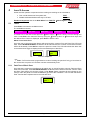
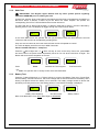
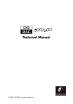
1
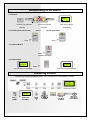
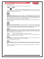
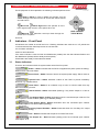
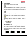
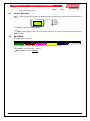
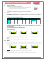
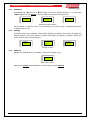
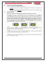
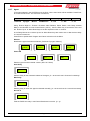
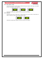
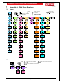
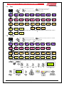
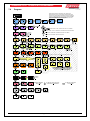
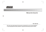
ZoneSense PLUS Fire Alarm Control Panel EN54 2 & 4 1997 Operation & Programming MAN 2374-10 Responding to an Alarm 1. Indicators FIRE ZONE 1 FIRE Z2 ZONE SEVEN ZONE 2 FAULT/DISABLED/TEST Common Fire Indicator Zone Fire Indicator (Steady) First Zone in Alarm. (Steady) 2. To Disable External Sounder and / or (Displayed) Sound Evacuation DISABLED ALARMS Press SILENCE RESOUND Press EVACUATE 3. To Silence Buzzer FIRE SILENCE BUZZER Press ALARM LED steady 4. To Reset Panel FAULT RESET EXECUTE Press RESET COMPLETE RESET 1st. LCD Screen Displayed 2nd. LCD Screen Displayed Disabling a Zone The following example DISABLES ZONE Place the keyswitch to the ENABLED position. MENU ENTER DISABLES SUB-MENU DISABLE Z1 ACTIVE DISABLES SUB MENU SCREEN DISABLE DISABLE ZONE2 ENABLE DISABLED ZONE 2 COMMON & ZONE2 DISABLED LED's WILL BE ILLUMINATED CANCEL PRESS CANCEL TO BACKOUT TO DEFAULT SCREEN TABLE OF CONTENTS 1 2 3 4 Introduction .......................................................................................................................... 1 1.1 Purpose ..................................................................................................................... 1 1.2 Scope ........................................................................................................................ 1 1.3 References................................................................................................................. 1 Controls – Front Panel Controls, Indicators & Testing....................................................... 2 2.1 System Controls and Indicators .................................................................................. 2 2.2 Levels of Access ........................................................................................................ 2 2.3 Passwords ................................................................................................................. 2 2.4 System Controls ......................................................................................................... 3 Indicators – Front Panel ....................................................................................................... 4 3.1 Status Indicators ........................................................................................................ 4 3.2 Common Indicators .................................................................................................... 5 3.3 Zone Indicators .......................................................................................................... 5 3.4 Liquid Crystal Display ................................................................................................. 5 3.5 Normal Operation ....................................................................................................... 6 3.6 Main Menu ................................................................................................................. 6 Level 1 Access ..................................................................................................................... 7 4.1 4.2 5 Status ........................................................................................................................ 7 4.1.1 Relays ............................................................................................................ 7 4.1.2 Sounders........................................................................................................ 8 4.1.3 Voltage........................................................................................................... 8 4.1.4 Software ......................................................................................................... 8 Faults ......................................................................................................................... 9 Level 2 Access ................................................................................................................... 10 5.1 5.2 6 Page No. Tests ........................................................................................................................ 10 5.1.1 Fault Test of Each Zone ............................................................................... 10 5.1.2 Walk Test ..................................................................................................... 11 5.1.3 Battery Test .................................................................................................. 11 Disables ................................................................................................................... 12 5.2.1 Zone, Relay or Sounder................................................................................ 12 5.2.2 Outputs ........................................................................................................ 12 Level 3 Access Programming ............................................................................................ 13 6.1 Password Entry ........................................................................................................ 13 6.2 System ..................................................................................................................... 14 6.3 6.2.1 Buzzer.......................................................................................................... 14 6.2.2 Mimic ........................................................................................................... 14 6.2.3 Code ............................................................................................................ 15 Program ................................................................................................................... 15 6.3.1 Zones ........................................................................................................... 15 6.3.2 Zone Delay................................................................................................... 16 6.3.3 Clock............................................................................................................ 16 6.3.4 Outputs ........................................................................................................ 16 6.3.5 Relays .......................................................................................................... 17 6.3.6 Fire Fan ....................................................................................................... 18 7 6.3.7 Agent ........................................................................................................... 19 6.3.8 Sounders...................................................................................................... 20 6.3.9 Indicate ........................................................................................................ 20 6.3.10 Display ....................................................................................................... 20 6.3.11 Zone Labels ............................................................................................... 20 6.3.12 EOL (END OF LINE) .................................................................................. 21 6.3.13 Zone S/C .................................................................................................... 21 Appendix A: EN54 Menu Structure .................................................................................... 22 7.1 Status ...................................................................................................................... 22 7.2 Faults ....................................................................................................................... 22 7.3 Test.......................................................................................................................... 23 7.4 Disable ..................................................................................................................... 23 7.5 System ..................................................................................................................... 24 7.6 Program ................................................................................................................... 25 8 Appendix B: Simple Example Wiring Diagram of a Basic FACP ...................................... 26 9 Appendix C: EN54 ABS Inner Front Panel Configuration Labelling................................. 28 ZONESENSE PLUS OPERATION & PROGRAMMING 1 Introduction 1.1 Purpose This manual is an instructional tool for the programming / reprogramming and operation of the ZoneSense PLUS Fire Alarm Control Panel (FACP). Using 3 levels of access the ZoneSense PLUS Fire Alarm Control Panel (FACP) is controlled and programmed this through the keypad on the front panel. Note: To assist in the programming process the screens or Menus presented to the operator are diagrammatically shown as an Appendix at the end of the document. 1.2 Scope The information within this manual is only available to and for the use of personnel engaged in the installation and operation of the ZoneSense PLUS FACP. ZoneSense PLUS has been designed to comply with major world standards. To ensure these standards are not compromised in any way installation staff and operators should; 1. Be qualified and trained for the task/s they undertake; 2. Be aware this manual should be read prior to the installation and commissioning of the ZoneSense PLUS FACP; 3. Observe anti-static pre-cautions at all times; and 4. If a problem is encountered or there is any doubt with respect to the operational parameters of the installation the supplier should be contacted. Note: It is strongly recommended that all front panel changes and or programming be appropriately recorded. 1.3 References ZoneSense PLUS Technical Manual ZoneSense PLUS Programming Manual Apollo Detector / Device Manuals Ampac Product Data Sheets British Standard: BS 5839 European Standard: EN54 Parts 2 & 4 Figure 1: Examples of the ABS (BX1) and Metal (BX10) Cabinets Page 1 ZONESENSE PLUS OPERATION & PROGRAMMING 2 Controls – Front Panel Controls, Indicators & Testing 2.1 System Controls and Indicators Legend: PCB Mounting Screws Bridge Mounting Holes Either Side of Bridge PCB Terminal Blocks ABS Bridge Figure 2: Exploded Front View of Membrane, Bridge and PCB for the ABS Model Key Switch Mechanism Mounting Screws Terminal Blocks PCB ABS Plastic Bridge LCD Front Membrane Figure 3: Exploded Top View of Membrane, Bridge and PCB 2.2 Levels of Access It is a requirement that access to a Fire Alarm Control Panel be restricted to trained authorised operators and technicians. To meet this requirement; Levels 1 access is view only, pressing the Menu button at level 1 gives access to the read only Fault and Status display menus.; Levels 2 access is restricted by way of keyswitch control. Access to level 2 is gained by switching the control switch from Normal to Enable.; Level 3, passwords are entered using the keys on the front panel. 2.3 Passwords Passwords for level 3 are a fixed 4 digit number (pre-commissioning factory set to 3333). The metal cabinet version of ZoneSense PLUS with an outer front door but no control enable key switch fitted has a link across the key switch terminals. Note: Sequential button presses must take place within 10 seconds of each other otherwise the display will return to its normal state. Page 2 ZONESENSE PLUS OPERATION & PROGRAMMING 2.4 System Controls The front panel consists of thirteen push button controls and a key switch. NORMAL ENABLED Controls, Normal – Enabled (Key Switch) A key switch for controlling system access between levels 1 and 2. All Control Enable key switches fitted to EN54 panels are keyed alike. This key is unique to Ampac. DELAY ACTIVE OVERRIDE Delay Override Used to turn Off the delays to outputs programmed in to the panel. The actual delays are programmed at level 3 and delay the action of Alarms and / or FBR outputs. The switch only operates when the panel is in alarm and a delay is active. Operating this switch under these circumstances will override delays to all zones sounding the alarms immediately and cause the Delay Active LED to turn off. (Refer also to Delay Active LED). Each zone can be individually programmed with Delay to Outputs and have individual time selection of 30 to 210 seconds. ALARMS SILENCE RESOUND Silence / Resound Alarms Active at access level 2 and is used to turn the “Alarms output” Off/On once they have been operated by an alarm condition. In the event of a new alarm being received the alarms will again operate. The same control is used to toggle on the “Alarms Output” once they have been silenced to reactivate the alarms that were originally operating. SILENCE BUZZER Silence Buzzer Is used for silencing either the audible fault warning or audible alarm warning (buzzer). For faults at access level 1 operation of the control will cause the buzzer to operate intermittently at 10 sec intervals. At access level 2 operation of the control will mute the buzzer though it will resound on any new event. In Fault the buzzer automatically silences on clearance of the fault. On Alarm the Buzzer Silence will only be active at access Level 1 and manually silenced as there is no automatic silencing of the fire condition. RESET Reset The Reset button is operational at access level 2 and is only used to return the control panel back to a Normal state from the fire Alarm condition. It will not reset a disablement condition. EVACUATE Evacuate Turns on and latches Alarm outputs, internal buzzer and the Fire LED at access level 2. The Silence Alarms and or Reset button silences the alarms activated by the Evacuate button. It does not operate the Ancillary relay though a programmable option allows the “Evacuate” to operate the “FBR” output. Page 3 ZONESENSE PLUS OPERATION & PROGRAMMING For the purposes of this explanation the following indicators perform these MENU ENTER Enter or Menu is used to update the program once the control settings have been set and to access the various menus and sub-menus. MENU ENTER Move Left Move Right allows the operator to move left or right through a menu or the options to be set. Move Up takes the cursor up or down through the menus and / or options. CANCEL CANCEL STEPS BACK THOUGH THE MENU functions; 3 Indicators – Front Panel All indicators are visible at access level one. If flashing indicators are used the on / off periods are >0.25 seconds and the flash frequencies are not less than: 1Hz for Alarm indications 0.2Hz for fault indications. If the same indicator is used for fault and disablement (isolate) then the fault indicator flashes and the disablement (isolate) will be steady and has priority. All indicators are steady unless otherwise stated. 3.1 Status Indicators There are ten indicators within the system status area of the front panel. POWER Power – Green Indicates that the FACP is supplied with power (mains or battery). Flashes when mains has failed. POWER FAULT Power Fault – Amber Common fault to the system power supply. Either mains or battery. SYSTEM FAULT System Fault – Amber Indicates a failure of the FACP to provide mandatory functions, e.g. software failure. EARTH FAULT Earth Fault – Amber Is an indication only to warn of a fault to earth that may affect a mandatory function. ALARMS STATUS Alarms Status– Amber Illuminated (flashing) if any Alarm Output is in fault or disabled. FIRE OUTPUT STATUS Fire Output Status– Amber Illuminates when the monitored open collector “Fire Out” output is in a fault condition (flashing) or disabled (steady). FAULT OUTPUT STATUS Fault Output Status– Amber Illuminates when the monitored open collector “Fault Out” output is in a fault condition (flashing). ANCILLARY OUPUT DISABLED Ancillary Output Disabled – Amber Illuminates when the “Ancillary Out” output relay is disabled (steady). TEST Test – Amber Indicates that the panel is in Walk Test mode. FIRE OUPUT ON Fire Output On – Red Illuminates (steady) when the monitored open collector “Fire Output” is on. Page 4 ZONESENSE PLUS OPERATION & PROGRAMMING 3.2 Common Indicators There are five indicators within the control area of the front panel. DELAY ACTIVE OVERRIDE Delay Active / Override – Amber When one or more zones are programmed with delay this indicator shall be “On” (steady) with the panel in the normal state or with a zone on the panel in alarm which is not programmed with Delay. The LED will flash when a zone programmed with Delay goes into an alarm state. If the Delay Override switch is not pressed prior to the pre-set Delay timing out, the indicator will continue to flash until timeout, at timeout it shall extinguish. This indicator is integral with the “Delay Override” button. A master reset will reset the original programmed state and delays on the panel. ALARMS SILENCE RESOUND Silence / Resound Alarms – Amber An indicator to show whether or not the Alarms have been silenced after they have been activated in response to an alarm condition. This indicator is integral with the “Alarms Silence / Resound” button. FIRE Fire – Red Common Fire indicator. (Also illuminated by operation of the Evacuate button). FAULT Fault – Amber Common Fault indicator illuminated by the presence of any fault. DISABLED Disabled – Amber Common Disablement indicator illuminated by the presence of any disablement. 3.3 Zone Indicators There are two indicators for each alarm zone fitted to the panel. FIRE ZONE 1 ZONE 2 FAULT/DISABLED/TEST Zone Fire – Red Indicator showing individual zone/s in the condition fire (steady). Zone Fault / Disable / Test – Amber Illuminated by a fault condition on individual zone (flashing), disablement of the zone will change the LED condition to (steady). A zone in fault that has been disabled will flash at a different rate than when only in fault, the off period shall be the same with the on period being x 3 of the fault flash rate. 3.4 Liquid Crystal Display The panel is fitted with an 8 x 2 LCD. The primary purpose is to display Zone alarm / fault / disable information and prompts for system commands come programming. Alarm, Fault and Isolate information is accessed through the Main Menu. When the FACP is in its normal state a default screen will be displayed. Examples of possible LCD Displays AMPAC MO 12 : 55 Default Screen 1 AMPAC O 22 C F 1/2 BATTERY Default Screen 2 Fault 1 off 2 Page 5 F 1/1 CHARGER Fault 1 off 1 ZONESENSE PLUS OPERATION & PROGRAMMING Battery Fault Charger or Power Fault 3.5 Normal Operation During normal operation the panel LCD default screen will display the panel name, the day and the time. Abbreviations: AMPAC MO 12 : 55 SU - SUNDAY MO - MONDAY TU - TUESDAY WE - WEDNESDAY TH - THURSDAY FR - FRIDAY SA - SATURDAY To access the Main Menu press Enter. Note: If the keypad controls are not used for a period of 2 minutes the display will return to the default screen. 3.6 Main Menu The Main Menu consists of; Level 1 STATUS FAULTS Level 2 Activate Control TEST DISABLES Level 3 Enter Password SYSTEM PROGRAM Press the Move Right / Move Left key to move through the menu. Press Enter to access the sub – menus. Move Right to access STATUS Page 6 ZONESENSE PLUS OPERATION & PROGRAMMING 4 Level 1 Access Is a read only menu that allows the operator to; Interrogate the panel to determine the state of selected outputs; STATUS View any faults that may be present on the FACP. FAULTS Note: Use Cancel at any time to step back out of the current Menu. 4.1 Status Press Enter to view the Status Menu. Press access the Status sub-menus. Move Right to move through the menu or Enter to Note: The sub-menu headings are in Italic. O/Ps Alarm 1 Alarm 2 Alarm 3 Alarm 4 Fire Fault AUC out Brigade On Off Relays On Off Fire Fan On Off Agent On Off Snders On Off I/Ps On Off Voltage Battery volts Charger volts System Volts Software Version Outputs Press Enter then Move Right or AUC Outputs status. Move Left to view the monitored Alarm 1 to 4, Fire, Fault or The LCD readout will indicate if the selected Output is; On and Normal, or Off and Normal, or Off and Disabled, or On and Disabled or Output is On and in Fault or Off and in Fault. FAULT ON / NORM FIRE OFF / NORM ALARM 1 OFF / NORM Sample Output Screens Meaning: The O/P is either On (activated) and Normal, or Off (de- activated) and Normal, or On (activated) and Disabled, or Off (de- activated) and Disabled. Note: The following are examples of some of the sub-menu but not all of them. 4.1.1 Relays Press Enter then Move Left or Move Right to select the required Relay (1 – 8). The LCD read out for each relay will indicate if the selected relay is On, Off or Disabled OR Press Move right to access Sounders. RELAY 8 ON RELAY 3 OFF RELAY 6 DISABLED Sample Relay Screens Meaning: A Relay is either On (activated), or Off (deactivated) or Disabled. Note: The relay’s control function is identified in the configuration documentation Page 7 ZONESENSE PLUS OPERATION & PROGRAMMING 4.1.2 Sounders Press Enter then Move Left or Move Right to select the required Sounder (1 – 8). OR press Move right to access Voltage. The LCD readout will indicate if the Sounder is; SOUNDER 8 OFF / NOR SOUNDER 7 OFF / FLT SOUNDER 2 ON / NOR Sample Sounder Screens Off and Normal, or Off and in Fault, or On and Normal, or On and in Fault, or Disabled and Normal, or Disabled and in Fault. 4.1.3 Voltage Press Enter press and the Battery Voltage will be displayed, pressingMove Right will display the Charger Voltage (27.2volts), pressing Move Right again will display the System Voltage OR Press Move right to access Software. SYSTEM V 27 . 8 V BATT V 27.0 V Voltage Screens 4.1.4 Software Displays the installed version of software. (This is for information only) SOFTWARE Ver 1 . 1 End of Sub – Menu Returning to STATUS in the Main Menu Move Right to access FAULTS Page 8 CHRGR V 27 . 2 V ZONESENSE PLUS OPERATION & PROGRAMMING 4.2 Faults Pressing Enter will display all faults in a sequential order. If there is more than one fault on the system the operator can scroll through each fault by using the Move Left and Right keys. Pressing Enter again at each Fault will display more detailed information. Accessing information on 2 Faults F 2/2 ZONE 8 F 1/2 ZONE 7 Press Enter FAULTS 2 Flt / s Move Right key to scroll OR Enter F1/2 EXTERNAL Enter to view detail ZONE 7 OPEN CCT ZONE 8 OPEN CCT F1/3 BATTERY F1/1 CHARGER LCD Screen Examples of System Status Faults System Fault Battery Fault Power Fault SYSTEM FAULT LED flashing POWER FAULT LED flashing POWER FAULT LED flashing POWER LED on POWER LED off Note: FAULT LED will be flashing (for all 3 FAULTS) Page 9 ZONESENSE PLUS OPERATION & PROGRAMMING 5 Level 2 Access At this level the operator is expected to have under gone training so as to be able to; Test crucial elements of the system and; TEST Disable dedicated facilities that may be in fault. DISABLE Enable the keyswitch then in the Main Menu from FAULTS Move Right for TEST 5.1 Tests Press Enter to access the available menus. The available menus are; Alarm Test Fault Test Walk Test Lamp Test Battery Test To initiate one of the above tests press the Move Right / Move Left key to move through the menu. Press Enter, then select the Zone by using the Move Up and / or Move Down keys until the desired Zone number is displayed, press Enter to start the test. Alarm Test of each Zone Once the test is commenced the Buzzer will sound and the common Fire and Zone Fire LED’s will flash. Press SILENCE BUZZER, the Buzzer will be silenced and the common Fire and Zone Alarm LED’s will be steady. Press Reset to return the panel to normal. The LCD will indicate the alarm has occurred and then toggle to display the Zone and descriptor of that Zone. Z1 : ZONE 1 LOBBY ALRM TST ZONE 1 Fire LCD Sequence Note: If a Zone has been programmed to be Non Latching the panel will only go into alarm for the normal time out period of 2 minutes and then automatically reset. 5.1.1 Fault Test of Each Zone Once the test is commenced the Buzzer will rapidly turn on and off and the common Fault and Zone Fault LED’s will flash. Press SILENCE BUZZER, the Buzzer will be silenced and the common Fault and Zone Fault LED’s will continue to flash. Press Reset (Reset complete will be indicated on the LCD) to return the panel to normal or Cancel to go back to the Test Menu. The LCD will indicate the Fault Test has been implemented on the selected Zone. FLT TST ZONE 1 Page 10 ZONESENSE PLUS OPERATION & PROGRAMMING 5.1.2 Walk Test IMPORTANT: The Brigade, Agent Release and any other system specific signalling should be DISABLED prior to initiating this test. A Walk Test, sets the Zone to Non latching and allows the technician to test detectors and MCP’s on that Zone. When a detector or MCP is put into alarm the “Alarm Outputs” will operate, the corresponding “Zone Fire” LED will flash and the buzzer will sound. The Zone will stay in Alarm until the MCP, or detector under test is reset or, the test is aborted by pressing Cancel. The LCD Display will toggle through the screens shown below. TESTING ZONE 1 WALK TST RUNNING CANCEL TO END In the TEST END screen the operator has ten (10) seconds to enter the time before the test will commence OR, the test can be started by pressing Enter. Only one zone at a time can be in test mode, all other zones will operate as normal. The LCD will display which Zone is the in Walk Test mode. Visual / Audible Indications - Lamp Test Press the Move Right and / or Move Left key to move to the Lamp Test menu, press Enter and each LED on the panel will be sequentially turned on for one second and then off again. The Buzzer will sound at the completion of the test. LAMP TST Press Enter LAMP>>>>> >>>>>>>TST Indicates the Test Progress TEST............ COMPLETE Test Successful Note: The operator has to visually confirm each LED illuminates. 5.1.3 Battery Test Press the Move Right and / or Move Left key to move to the Battery Test menu, Press Enter and the Battery Test will commence, that is the Charger will be disconnected from the battery and a dummy load placed across the battery for 60 seconds. The battery voltage should be above that specified (23.5 volts) at the end of the testing period, if not a FAILED message is displayed. BATT TST 26.1 Battery Test Underway BATT TST PASS Test Successful Back in the Main Menu From TEST Move Right to DISABLES Page 11 BATT TST FAIL Battery Failure ZONESENSE PLUS OPERATION & PROGRAMMING 5.2 Disables To display the number of Disables press Enter to access the menus then Move Left or Right to select the required menu. The number of Disable will be displayed. Zone Zones 1 to 8 are Active or Disable Outputs Relay Relays 1 to 8 are Active or Disable Alarm 1 - 4 5.2.1 Fire Fault Move Sounder Sounders 1 to 8 are Active or Disable Anc. Out Zone, Relay or Sounder Press Enter and use the Move Left or Move Right keys to select the Zone, Relay or Sounder number then the Move up to key disable or Move Down key to make active (set) the required Zone, Relay or Sounder. ZONES X DISABLED Press ZONE 1 DISABLED ZONE 1 ACTIVE Select Zone Number Enter set, Active or Disabled Note: X denotes the Zone number, substitute Relay or Sounder for those menus. If a Zone or Zones are Disabled the Disabled LED for that Zone and the common Disabled LED will be illuminated. If a Relay or Relays, Sounder or Sounders are disabled only the common Disable LED will be illuminated. The Disable can be deactivated while in the Output menu or repeating the steps above to enable (make Active) individual Zones. 5.2.2 Outputs Press Enter to access the Disable - Outputs sub-menus as seen below Alarm 1 to 4 Fire Fault Anc. Out Use the Move Right or Move Left keys to select the required menu and the Move Up key to Disable or the Move Down key to active. ALARM 1 ACTIVE ALARM 1 DISABLED If the: Alarm is Disabled the Alarm LED will be illuminated. Warning System is Disabled the Warning System LED will be illuminated. Fault is Disabled the Fault / Disable LED will be illuminated. Anc. Out is disabled the common Disabled LED will be illuminated. Press Cancel to back out of the Disable Menu to the Main Menu. Move Right to Enter the PASSWORD for level 3 Access Note: Reminder: Press ENTER at the end of each selection to update the program. Page 12 ZONESENSE PLUS OPERATION & PROGRAMMING 6 Level 3 Access Programming Level 3 is a technical level that allows a technician to; Initialise the FACP so it is capable of recognising how the system is constructed; and SYSTEM Program how it will present information as well as how it will react to a change of state of an input and / or output. PROGRAM 6.1 Password Entry Returning to Faults in the Main Menu, Move Right for Password Entry to Level 3. Press Enter and a flashing cursor will appear below the word PASSWORD. By using the Move up and Move down keys the number on the screen will be incremented accordingly. Once the first password number has been set use the Move right key to move to the next number to be set. This operation has to be repeated four times as the PASSWORD is a four digit code. If a number is incorrect it can be changed by using the Move Left and Right keys to position the cursor over the incorrect number. Once the four numbers have been set pressing Enter initiates the verification of the PASSWORD that has been entered. An incorrect PASSWORD will be displayed as REJECTED and return the operator to the first menu. ENTER PASSWORD Press Enter PASSWORD 0000 Enter Password PASSWORD ACCEPTED Correct Password Entry If the PASSWORD is accepted the screen will display STATUS. Use the through the menu to SYSTEM OR PROGRAM. Right keys to move Note: The operator has 2 minutes to complete Password entry. Failure to enter the Password in this time results in the panel reverting to the default screen. Note: The System and Program Menus are not accessible if an Alarm condition exists even if the correct Password is entered. Page 13 ZONESENSE PLUS OPERATION & PROGRAMMING 6.2 System After entering the Level 3 Password and moving to the SYSTEM menu press Enter and the; 1. Zone DISABLED LED’s will illuminate; Common DISABLED LED will flash; and the LCD will display; BUZZER SYSTEM DISABLED SYSTEM DISABLED And then BUZZER Ignoring Buzzer, Mimic and Code menus ( explained below ) use the Move Right or Move Left keys to move through the menu and the Move Up key to set YES or Move Down key to set No. Yes meaning the facility / board / card has been fitted to the FACP and will be programmed in the Programming Menu, No meaning it has not been fitted and will not appear in the Programming Menu. RLY CARD YES BRIGADE YES BUZZER Typical Screen examples of the System Menu Buzzer Earth Mon Sndr Card 6.2.1 Ind Card Brigade Relay Board Switch Ind Fire Fan I/P Card Mimic Agent Code Buzzer This is the only facility in this Menu that has a Sub – Menu. Press Enter to access the Sub – Menu then theMove Left orMove Right key to select either; Resound, Alarm or XTRA OUTPUT then Enter. Set the Resound, Alarm by using the Move Up key to Yes (activate on alarm) or Move Down key for No (not activate on alarm). Set the XTRA OUTPUT option to act as a Reset or Buzzer function as per the system design configuration. If the XTRA OUT output is selected set as a Reset or Buzzer function by using the Buzzer or Move Down keys for Reset. Press Enter to update the program. XTRA OUT RESET Resound Set to YES 6.2.2 ALARM YES Alarm Set to YES Move Up for RESOUND YES XTRA OUTPUT Mimic This tells the FACP how many Zone Mimic Indicator Boards are on the system hence how many to look for. Set the number by using the Move Down and / or Move Up keys to increment to the desired number (maximum of 8). MIMIC 8 Page 14 ZONESENSE PLUS OPERATION & PROGRAMMING 6.2.3 Code Code is the National Standard the Panel complies with. This is factory set and can not be altered. CODE EN54 Back out to the Main Menu using the CANCEL key and move from the SYSTEMS Menu to the PROGRAM Menu using the Move Right key. When the CANCEL key is pressed the LCD will display SYSTEM ENABLED for one second and all the Disabled LED’s will be turned off. 6.3 Program Note: From the Zones Menu use the Move Right key to advance through the PROGRAM Menu. SYSTEM ENABLED Pressing Enter to access the Program Menu will again disable the panel and the LED’s will illuminate as they did in the Systems Menu. The PROGRAM Menu consists of; Zones Agent 6.3.1 Zone Delays Sounders Clock Outputs Indicate Display Relays Fire Fan Zone Labels EOL Zone S/C Zones Press Enter and the Zones Menu will be displayed on the LCD screen. Pressing Enter again will access the Zones sub menu where first the Move Right and Move Left keys are used to select the Zone number and the Move Up and ZONE 2 NORMAL ZONE AVF 4 ZONE 6 AGENT 1 Sample Zone Screens Move Down keys are used to set the functions within that Zone. The functions are; Normal Normal is selected if the Zone is required to initiate an alarm and latch until reset. AVF If AVF, (Alarm Verification Facility) or Co-incidence is set active a delay and re-sampling period is initiated to confirm an alarm condition actually exists on that Zone. Non Latch Non Latch if set will initiate an alarm only when the Zone is in alarm. Agent 1 Agent 2 Note: Any Zone may be allocated to be a trigger zone Select the Zone to initiate the release of the agent. If zones have already been allocated to change the zone first remove the allocation of the current zone and press ENTER to update the program then, reallocate the new zone and again press ENTER to update the program. Page 15 ZONESENSE PLUS OPERATION & PROGRAMMING Double Knock Sets Zones to output an Alarm condition from the Main Board Alarm Output when any 2 of the Zones selected in this screen go into alarm. Relay outputs are unaffected and will operate when any Zones goes into alarm. 6.3.2 Zone Delay Press Enter to assign an alarm delay of between 30 and 300 seconds to a Zone using the Move Up and / or Move Down keys to select the Zone, (1- 8), then select the delay, then Enter to update the Program. PROGRAM UPDATED ZONE 2 30 Press Cancel to return to the Zone menu and then Move Right to access the Clock Menu. 6.3.3 Clock To set the day and time press Enter and the day will be highlighted. Use the Move Up or Move Down keys to step through the days of the week, then the Move Right key to access the hours and minutes. To access each digit use the Move Right and Move Left keys and to increment each digit use the Move Up and Move Down keys. Press Enter to set the time and thenMove Right to access OUTPUTS Menu. CLOCK FR 11 : 21 6.3.4 Outputs To assign Zones that will activate the monitored outputs press Enter and the sub menu will be made available for programming. The sub menu consists off; Alarm 1 to 4 ANC Out BGD ALM 1 BGD ALM 2 Fire Out To move through the sub menu use the Move Right and Move Left keys. For each output press Enter, then the Move Left and Move Right to select the Zones that will ALARMS O/P 1234 ALARMS O/P 1 4 All 4 Alarms Selected Alarms 1 and 4 Selected Press Enter to Update the Program then Cancel to return to the Sub Menu and the Move Right and or Move Left keys to move through it. Repeat the above procedure to set or change the other Outputs as required. Page 16 ZONESENSE PLUS OPERATION & PROGRAMMING 6.3.5 Relays Press Enter then use the Move Right and / or Move Left keys to select a relay that will be operated by the selected functions in the sub - menu . Press Enter to access the sub – menu then Move Right and /or Move Left keys to toggle through the sub - menu structure. The sub menu consists off; Zone Alarm Zone Fault Zone Disable Input Switch Reset For: R# Zone Alarm R# Zone Fault R# Zone Disable R# Input R# Switch R# Reset Press Enter then Move Right and /or Move Left keys to select the Zone Alarm / Fault / Disable, Input or Switch then Enter. Use the Move Right and / or Move Left keys to select the Zones and the Move Up or Move Down keys to set it to be active or in-active. Active meaning the Zone Alarm / Fault / Disable, Input or Switch will operate the Relay where as in–active will prevent them from operating that relay. RELAY 3 R3 Z . ALM 1...3...5...7... R2 SWIT ....3...5...7 Press Enter to update the Program and the Cancel to back out to the previous menu. For: Reset Latch R3 ACFIS NO R2 LATCH YES R5 NO RESET Press Enter then the Move Right and /or Move Left keys to select Reset or Latch then the Move Up or Move Down keys to set for Yes or No. Yes sets the Relays to be reset or Latched. Press Enter to update the Program and Cancel to back out to the previous Menu Page 17 ZONESENSE PLUS OPERATION & PROGRAMMING 6.3.6 Fire Fan The sub menu consists off; Alarm For: Inhibit Alarm Function Inhibit FAN 2 Press Enter then use the Move Right and / or Move Left keys to select the Fire Fan that will be controlled by the selected functions in the sub - menu . Press Enter to access the sub – menu then Move Right and /or Move Left keys to toggle through the sub - menu structure. Press Enter then Move Right and /or Move Left keys to select the Zone/s that will activate or deactivate the control when it is in alarm or inhibited. Use the Move Up or Move Down keys to set it to active or in-active. Active meaning the Zone will operate the control where as in–active will prevent that Zone from having control. ALARM 2.................. For: INHIBIT 3.................. Function Press Enter and the cursor will flash over the number 0, 1 or 2, then press the Move Up or Move Down keys to select the required Function. Selection relies on how the inputs / outputs have been physically wired as outlined below. 1. Equates to a 3 wire Start / Stop, Run & Common. 2. Equates to a 4 wire Start / Stop, Run, Stop & Common. 3. Equates to a 5 wire Start / Stop, Run, Stop, Fault & Common. FUNCTION 2 Press Enter to update the Program and then Cancel to back out of the Menu. Page 18 ZONESENSE PLUS OPERATION & PROGRAMMING 6.3.7 Agent If Yes was selected in the SYSTEM menu the Sub – Menu seen below will be available. Press Enter to access the sub-menu. The sub-menu consists off; Release Solenoid Pyrogen Metron Press Sw Auto Delay Man Delay No LCP’s NO/NC/None 0 – 60s 0 – 60s 0 - 16 Using Move Right or Move Left select either Release, Sense Switch, Auto Delay, Manual Delay or the Number of Local Control Panels ( LCP’s ), then the Enter key to access the menu and the Move Up or Move Down keys to set the required function or number. In the Delay Menus the Move Up and in 5 second increments. Move Down keys are used to set or alter the time delay Press Enter to update each Program and Cancel to back out of the Menu. Release Identifies the type of release mechanism. [Solenoid / Pyrogen / Metron]. RELEASE SOLENOID RELEASE METRON RELEASE PYROGEN RELEASE CONSTANT Press SW PRESS SW N/O PRESS SW N/C PRESS SW NONE Sets the type of monitor release contact. (NO / NC / None) Auto Delay AUTO DLY 15 Sets the delay for the automatic release of the agent. [0 – 60 seconds set in 5 second increments] Man Delay MAN. DLY 35 Sets the delay for when the agent is released manually. [0 – 60 seconds set in 5 second increments] No LCP’S LCPS 1 Tells the FACP how many Local Control Panels are in service. [0 – 4] Page 19 ZONESENSE PLUS OPERATION & PROGRAMMING 6.3.8 Sounders Press Enter then use the Move Right and Move Left keys to select a sounder. Press Enter again and use the Move Right and Move Left keys to select a Sounder, Press Enter again and the Move Up and Move down keys to set that Sounder to a Zone to activate or not activate the selected sounder. SOUNDERS SOUNDER 4 .........4............ SOUNDER 3 ...2...4...6....... Press Enter to update each Program and Cancel to back out of the Menu. 6.3.9 Indicate If a General Indicator Card is selected via the System Menu then all the tri-coloured LED’s default to red. To alter the colour of the LED select Indicate then press Enter. The LCD will display “Style 1”. Use the the different styles. Move Up and the Move Down keys to scroll through STYLE 1 LED's all Red Window for Slip In Label STYLE 2 LED's Red ( left ) Yellow ( right ) STYLE 3 LED's Row 1 Both Red Row 2 Both Yellow Row 3 Both Green Other rows follow the same pattern STYLE 1 RED RED Windows for Slip in Label RED Windows for Slip in Label YELLOW Windows for Slip in Label RED RED YELLOW Windows for Slip in Label YELLOW GREEN Windows for Slip inGREEN Label Examples of the different “Styles “available through the Indicate Menu are shown above. Note only the top display is shown in the first 2 examples where as the first 3 top displays are shown in Style 3 Once the “Style has been selected press Enter to update the Program and Cancel to back out of the Menu. 6.3.10 Display To set the message, FACP or company name press Enter and use the Move Right and Move Left keys to move through the word to select a letter and the Move Up and the Move Down keys to move through the alphabet. A maximum of 16 characters are available for this message. AMPAC < INFO > Press Enter to update each Program and Cancel to back out of the Menu. 6.3.11 Zone Labels To name the Zones press Enter then the Move Right and / or the Move Left keys to select a Zone. Press Enter and use the Move left and / or Move Right keys to move the cursor through the structure of the word and the Move Up and Move Down keys to move through the alphabet. Z LABELS ZONE 1 Z1 : LOBBY Press Enter to update each Program and Cancel to back out of the Menu. Page 20 ZONESENSE PLUS OPERATION & PROGRAMMING 6.3.12 EOL (END OF LINE) Press Enter and use the Move Up and Move Down keys to select the EOL option. The options are CAP 10f, RES 3K3, 4K7, 6K8 &10K. EOL CAP 10 u F EOL RES 3 K 3 EOL RES 4 K 7 Press Enter to update each Program and Cancel to back out of the Menu. 6.3.13 Zone S/C Press Enter and use the Move Up or Move Down key to set the panel to initiate either an Alarm or Fault when a Zone short circuited condition exists. ZONE S / C ALARM ZONE S / C FAULT Press Enter to update each Program and Cancel to back out of the Menu. Page 21 ZONESENSE PLUS OPERATION & PROGRAMMING 7 Appendix A: EN54 Menu Structure 7.1 Status PRESS ENTER PRESS THESE KEYS TO SET YES / NO, OFF / ON, OFF NORMAL PRESS: MOVE FORWARD OR BACKWARD THROUGH THE MENU PRESS MOVE FORWARD THROUGH THE MENU LEGEND: MENU ENTER STATUS MENU ENTER CANCEL MENU ENTER RELAYS BRIGADE OUTPUTS MENU ENTER MENU ENTER FIRE FAN MENU ENTER MENU ENTER ALARM 1 OFF/NORM ALARM 1 OFF / ON RELAY 1 OFF / ON FAN 1 OFF / ON ALARM 2 OFF/NORM FAULT OFF / ON RELAY 2 OFF / ON ALARM 3 OFF/NORM DISABLE OFF / ON ALARM 4 OFF/NORM FIRE OFF/NORM SOUNDERS AGENT MENU ENTER MENU ENTER CANCEL INPUT PRESS CANCEL AT ANY TIME TO BACK OUT OF THE MENU VOLTAGE MENU ENTER MENU ENTER SNDR 1 OFF/NORM INPUT 1 OFF / ON BATT V 26.8V FAN 2 OFF / ON SNDR 2 OFF/NORM INPUT 2 OFF / ON CHRGR V 27.0V RELAY 3 OFF / ON FAN 3 OFF / ON SNDR 3 OFF/NORM INPUT 3 OFF / ON SYSTEM V 27.0V BATT FAIL OFF / ON RELAY 4 OFF / ON FAN 4 OFF / ON SNDR 4 OFF/NORM INPUT 4 OFF / ON ALARM 2 OFF / ON RELAY 5 OFF / ON SNDR 5 OFF/NORM INPUT 5 OFF / ON FAULT OFF/NORM RELAY 6 OFF / ON SNDR 6 OFF/NORM INPUT 6 OFF / ON ANC OUT OFF/NORM RELAY 7 OFF / ON SNDR 7 OFF/NORM INPUT 7 OFF / ON RELAY 8 OFF / ON SNDR 8 OFF/NORM INPUT 8 OFF / ON 7.2 AGENT OFF/NORM SOFTWARE VER E1.2 Faults LEGEND: FAULTS MENU ENTER MENU ENTER MENU ENTER FAULTS 2 Flt/s MENU ENTER PRESS ENTER TO GO TO MENU PRESS TO VIEW DETAILS OF EACH FAULT CANCEL F1/2 FIRE FAN MENU ENTER FIRE FAN MISSING CANCEL F2/2 FIRE CTRL MENU ENTER FAN CTRL MISSING Page 22 PRESS CANCEL AT ANY TIME TO BACK OUT OF THE MENU OR STOP TEST ZONESENSE PLUS OPERATION & PROGRAMMING 7.3 Test LEGEND: TEST MENU ENTER MENU ENTER MENU ENTER ALARM TE S T MENU ENTER MENU ENTER ZONE 2 TE S T ZONE 3 TE S T ZONE 4 TE S T ZONE 5 TE S T ZONE 6 ACTIVE ZONE 5 TE S T ZONE 6 TE S T ZONE 1 TE S T ZONE 2 TE S T ZONE 3 TE S T ZONE 4 TE S T ZONE 1 TE S T ZONE 2 TE S T ZONE 3 TE S T ZONE 4 TE S T LAMP>>>> TEST>>>> MENU ENTER MENU ENTER BATTERY TE S T 7.4 ZONE 6 TE S T ZONE 5 TE S T ZONE 8 ACTIVE ZONE 7 TE S T ZONE 8 TE S T ZONE 7 TE S T ZONE 8 TE S T EXAMPLE OF TESTING ZONE 4 WALK TST ZONE 4 TEST.... COMPLETE CANCEL TO END TEST END 5MIN SEC PRESS ENTER TO START TEST ( TEST PERFORMED FOR TIMEOUT ) PRESS CANCEL TO HALT BATT 60s 26.8 V MENU ENTER ZONE 7 ACTIVE PRESS ENTER TO TEST MENU ENTER LAMP TE S T PRESS CANCEL AT ANY TIME TO BACK OUT OF THE MENU OR STOP TEST PRESS TO INCREMENT UP DOWN ZONE NUMBER TO BE TESTED ZONE 1 TE S T MENU ENTER WALK TE S T CANCEL CANCEL MENU ENTER FAULT TE S T PRESS ENTER TO START TEST BATT TST PASS Disable LEGEND: DISABLE MENU ENTER PRESS ENTER TO ACCESS MENU CANCEL PRESS CANCEL AT ANY TIME TO BACK OUT OF THE MENU MENU ENTER PRESS MOVE FORWARD / BACKWARD THROUGH THE MENU CANCEL MENU ENTER Z ONES 0 DISABLED ZONE 2 ACTIVE ZONE 1 ACTIVE MENU ENTER MENU ENTER OUTPUTS 0 DISABLED PRESS TO MAKE ACTIVE PRESS TO DISABLE ZONE 7 ACTIVE ZONE 4 ACTIVE ZONE 5 ACTIVE ZONE 6 ACTIVE ALARM 4 ACTIVE ANC OUT ACTIVE FIRE ACTIVE FAULT ACTIVE RELAY 6 ACTIVE RELAY 7 ACTIVE ZONE 8 ACTIVE EXAMPLE OF ISOLATING ZONE 1 ALARM 1 ACTIVE MENU ENTER ZONE 3 ACTIVE ALARM 2 ACTIVE ALARM 3 ACTIVE THESE SCREENS WILL DISPLAY THE NUMBER OF ISOLATES 0 TO 8 RELAYS 0 DISABLED MENU ENTER RELAY 1 ACTIVE RELAY 2 ACTIVE EXAMPLE OF ACTIVATING RELAY 2 SOUNDERS 0 DISABLED MENU ENTER SNDR 1 ACTIVE RELAY 3 ACTIVE RELAY 5 ACTIVE RELAY 8 ACTIVE NOTE: THESE MENUS ARE ONLY AVAILABLE IF RELAYS & SOUNDERS HAVE BEEN CHANGED TO YES IN THE SYSTEM MENU MENU ENTER SNDR 2 ACTIVE RELAY 4 ACTIVE SNDR 3 ACTIVE SNDR 4 ACTIVE SNDR 5 ACTIVE SNDR 7 ACTIVE SNDR 6 ACTIVE SNDR 8 ACTIVE e.g. The following example DISABLES ZONE 2. Place the keyswitch to the ENABLED position NORMAL ENABLED PRESS IN ORDER MENU ENTER DEFAULT SCREEN MENU ENTER DISABLES SUB-MENU STATUS MENU DISABLE Z1 ACTIVE DISABLES SUB MENU SCREEN DISABLE 0 DISBLED MENU ENTER FAULTS MENU DISABLE DISABLE ZONE2 ENABLE Page 23 TESTS MENU DISABLED DISABLES MENU DISABLES MENU SCREEN ZONE 2 COMMON & ZONE2 DISABLED LED's WILL BE ILLUMINATED CANCEL PRESS CANCEL TO BACKOUT TO DEFAULT SCREEN ZONESENSE PLUS OPERATION & PROGRAMMING 7.5 System ENTER MENU PA S S WORD ENTER S Y S T EM MENU ENTER BUZZER MENU ENTER FACTORY DEFAULT PASSWORD IS 3333 EXAMPLE OF SETTING PASSWORD 0123 EXAMPLE SET RESOUND TO YES THEN MOVE TO ALARM YES EARTH MON YES / NO MENU ENTER MENU ENTER PA S S WORD 0000 PA S S WORD 0100 PA S S WORD 0120 PA S S WORD 0123 ALARM YES / NO RESOUND YES / NO UPDATE PROGRAM MOVE TO ALARM YES / NO BRIGADE YES / NO RELAYS YES/ NO FIRE FAN YES / NO NOTES: TO ADD OR DELTE FROM THE SYSTEM SET TO YES OR NO AND THEN GO TO THE PROGRAM MENU TO SET THE OPERATIONAL PARAMETERS IF THESE OPTIONS ARE NOT SET TO YES THEY WILL NOT APPEAR IN THE TEST, STATUS OR PROGRAM MENU AGENT YES / NO MENU ENTER PA S S WORD ACCEPTED SOUNDERS YES / NO SYSTEM SW INDIC YES / NO MENU ENTER INDICATE YES / NO CANCEL LEGEND: MENU ENTER INPUTS YES / NO PRESS ENTER TO ACCESS MENU AND UPDATE PROGRAM OR CHANGE MENU PRESS: MOVE FORWARD OR BACKWARD THROUGH THE MENU PRESS THESE KEYS TO SET YES / NO MIMIC 0 TO 8 PRESS MOVE FORWARD THROUGH THE MENU CANCEL CODE EN54 FACTORY SET CAN NOT BE C H ANGED Page 24 PRESS CANCEL AT ANY TIME TO BACK OUT OF THE MENU ZONESENSE PLUS OPERATION & PROGRAMMING 7.6 Program Note: Any Zone may be allocated to be a trigger zone. Select the Zone (1 to 8 ) to initiate the release of the agent. If zones have already been allocated to change the zone first remove the allocation of the current zone and press ENTER to update the program then, reallocate the new zone and again press ENTER to update the program. PROGRAM MENU ENTER ZONES MENU ENTER SELECT ZONE 1 - 8 NORMAL NON LATCH AVF AGENT T2 AGENT T1 DOUBLE KNOCK 1 TO 8 LEGEND: 8 ZONE DELAY MENU ENTER SELECT DELAY SELECT ZONE 1-8 ASSIGN MCP 1 TO A ZONE MENU ENTER CANCEL PRESS CANCEL AT ANY TIME TO BACK OUT OF THE MENU CANCEL MENU ENTER CLOCK MENU ENTER SELECT D AY T I ME C H ANGE DAY TIME PRESS MOVE FORWARD THROUGH THE MENU MOVE THROUGH DAY TIME O U T P U TS MENU ENTER ALARM 2 ZN 1 TO 8 ALARM 1 ZN 1 TO 8 ON MENU ENTER RELAYS MENU ENTER SELECT RELAY 1 TO 8 MENU ENTER OFF 1 TO 8 MENU ENTER FIRE FAN MENU ENTER SELECT FA N 1,2,3,4 MENU ENTER A GENT SOUNDERS MENU ENTER SET SNDR # 12345678 MENU ENTER R# I/P 1 TO 8 CANCEL INHIBIT ZN 1 TO 8 MENU ENTER INDICATE MENU ENTER UPDATE MENU SET ZONE # 12345678 Z LABELS EOL 10uf ZONE S/C MENU ENTER MENU ENTER MENU ENTER EDI T TEXT 3 4 5 MENU ENTER MENU ENTER RELEASE PYROGEN PRESS S/W N/O RELEASE SOLENOID PRESS SW N/O RELEASE METRON RELEASE CONSTANT SELECT R Y G SELECT LED 1-16 SELECT ZONE EOL RES 3K3 ZONE ALARM MENU ENTER FIRE OUT EVAC Y/N R# SWITCH 1 TO 8 N: NO RESET BACKOUT OF MENU YES EDI T TEXT EOL RES4K7 NO FUNCTION 3,4,5 WIRE PRESS SW NONE MENU ENTER DISPLAY ######## SELECT BGD ALM 2 ZN 1 TO 8 MENU ENTER MENU ENTER MENU ENTER R# Z-ISOL 1 TO 8 UPDATE MENU ALARM ZN 1 TO 8 ON R# Z-FLT 1 TO 8 OFF 1 TO 4 SELECT BGD ALM 1 ZN 1 TO 8 Y: YES MENU ENTER OFF 1 TO 8 ANC OUT ZN 1 TO 8 ALARM 4 ZN 1 TO 8 ALARM 3 ZN 1 TO 8 UPDATE MENU EXAMPLE OF ACTIVATING ZONE TO TURN ON/OFF SELECTED OUTPUT R# Z-ALRM 1 TO 8 ON PRESS ENTER TO GO TO SUB MENU, SET MENU OR UPDATE PROGRAM PRESS MOVE FORWARD / BACKWARD THROUGH THE MENU MENU ENTER EXAMPLE OF SELECTING FUNCTION WIRE TO BE USED AUTO DELAY SET 0 - 60S MAN DELAY SET 0 - 60 L CS 1 SET 0 - 60 SEC SET 0 - 60 SEC SET 1 TO 4 NOTE: THESE MENUS ARE ONLY AVAILABLE IF RELAYS, FIRE FAN, AGENT SOUNDERS HAVE BEEN CHANGED TO YES IN THE SYSTEM MENU R: RED Y: YELLOW G: GREEN TO EDIT DISPLAY TEXT USE EOL RES 6K8 TO MOVE THROUGH THE ALPHABET / NUMBERS EOL RES 10K ZONE FAULT Page 25 TO MOVE THROUGH THE WORD INPUTS RS485 COM SP C/C ALT TB3 - TB2 + S P A R E Class Change Input EOL Capacitor Rear of Main Board CN6 PSU Control from CN2 of the P/S CN8:27V In from CN4 of the P/S CN10: 27V Out to Internal Cards & Boards TB14 + Z5 - + Z6 - + Z7 - + Z8 - DETECTOR ZONES Open Collector O/Ps Current Limited to 25mA. and Detector Removal Facility Available TB13 + Z1 - + Z2 - + Z3 - + Z4 - ALL Un-used Zones MUST be Terminated in an EOL Power Supply Main Board Internal Wiring Comms Link LED Mimic, LAM, 8 Way Remote Relay Board Note: Comms Link is required when only one Systems Comms board is used Alert Input Maximum of 32 Devices per Zone +1 - EOL Resistor +3 TB4 - - EOL Resistor 4 X Monitored Alarms Outputs Maximium 500mA / 24V +2 EOL Resistor 1 +4 - FAULT + Monitored Open Collector 30 mA O/P's FIRE + Alarm O/P's EOL Resistor Required FAULT N/O C N/C Voltage Free Contacts 1A/30V ANCILLARY TB5 N/O C N/C 7 5 3 1 CN5 2 8 6 CN2 4 2 OV +27V GND 1 2 3 DC OUTPUT CN4 -BATT+ TB2 Power Supply Unit ( BRD25PSUA ) - EOL Resistor - RST 12v Batt - - 12v Batt 24VDC OUT Monitored 24V 500mA O/P TB12 + +24v / 100mA 3 Sec Reset 0v Pulse Front of Main Board Illustrated External Cabling + Page 26 + 8 EOL Termination Values 10uf,3K3, 4K7, = Zone 6K8 or 10Kohms 10Kohms Monitored O/P's = ZONESENSE PLUS OPERATION & PROGRAMMING Appendix B: Simple Example Wiring Diagram of a Basic FACP ZONESENSE PLUS OPERATION & PROGRAMMING Page 27 ZoneSense Plus Installation Commissioning & Operation 9 Appendix C: EN54 ABS Inner Front Panel Configuration Labelling ZONE 1 2 3 4 5 6 7 8 BELL CONFIGURATION NORM / AVF / NON / SELF / AT1 / AT2 NORM / AVF / NON / SELF / AT1 / AT2 NORM / AVF / NON / SELF / AT1 / AT2 NORM / AVF / NON / SELF / AT1 / AT2 NORM / AVF / NON / SELF / AT1 / AT2 NORM / AVF / NON / SELF / AT1 / AT2 NORM / AVF / NON / SELF / AT1 / AT2 NORM / AVF / NON / SELF / AT1 / AT2 EOL VALUE MCP ZONE No LAM's A 3K3 / 4K7 / 6K8 / 10K / CAP 1/2/3/4/5/6/7/8 1/2/3/4 WARN SYS ACF ASE ALARM B ALARM 1 B ALARM 2 RELAY 1 A/ F/I A/ F/I A/ F/I A/ F/I A/ F/I A/ F/I A/ F/I A/ F/I C B INPUT SWITCH ACF ISOL RESET LATCHING Y/N Y/N Y/N RELAY 2 A/ F/I A/ F/I A/ F/I A/ F/I A/ F/I A/ F/I A/ F/I A/ F/I Y/N Y/N Y/N RELAY 3 A/ F/I A/ F/I A/ F/I A/ F/I A/ F/I A/ F/I A/ F/I A/ F/I Y/N Y/N Y/N RELAY 4 A/ F/I A/ F/I A/ F/I A/ F/I A/ F/I A/ F/I A/ F/I A/ F/I RELAY 5 A/ F/I A/ F/I A/ F/I A/ F/I A/ F/I A/ F/I A/ F/I A/ F/I D Y/N Y/N Y/N Y/N Y/N Y/N RELAY 6 A/ F/I A/ F/I A/ F/I A/ F/I A/ F/I A/ F/I A/ F/I A/ F/I Y/N Y/N Y/N RELAY 7 A/ F/I A/ F/I A/ F/I A/ F/I A/ F/I A/ F/I A/ F/I A/ F/I Y/N Y/N Y/N RELAY 8 A/ F/I A/ F/I A/ F/I A/ F/I A/ F/I A/ F/I A/ F/I A/ F/I Y/N Y/N Y/N SOUNDER 1 SOUNDER 2 SOUNDER 3 SOUNDER 4 SOUNDER 5 SOUNDER 6 SOUNDER 7 SOUNDER 8 FAN 1 SOLENOID / PYROGEN / METRON 0 / 15 / 30 / 60 / 0 / 15 / 30 / 60 / NO / NC / NA 1/2/3/4 FAN 3 FAN 4 G E AGENT RELEASE AUTO DELAY - SECS MANUAL DELAY - SECS PRESSURE SWITCH No OF LCP'S FAN 2 F 3/4/5 Y/N Y/N 3/4/5 Y/N Y/N 3/4/5 Y/N Y/N H 3/4/5 Y/N Y/N Instructions to Installer A, B, D, F and H Using a permanent marking pen cross out the conditions that do not apply. C, E, and G Using a permanent marking pen cross (X) the box for the option that is set for the Zone. A Indicates the configuration of each Zone Normal (NORM), AVF, Non-latching (NON), Self latching (SELF) Agent 1 (AT1), Agent 2 (AT2). B Indicates what EOL value has been selected, what Zone has MCP’s, and the number of LAM’s controlled by the FACP. C Indicates what Zones controls what Main Card Output. D Indicates if Alarm (A), Fault (F) or Isolate (I) controls the designated relay and the type of input it has. E Indicates what Zones control what Sounders. F Indicates the type of Agent Release fitted the type and duration of delay and the number Local Control Stations fitted. G Indicates what Zone controls what Fan circuit. H Indicates the type of wire Function and whether or not latching and / or ACF Isolate is set. Page 28 INHIBIT ZONES FUNCTION LATCHING ACF ISOLATE UNCONTROLLED DOCUMENT NOTE: Due to AMPAC’s commitment to continuous improvement specifications may change without notic e