1
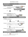
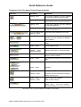
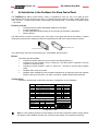
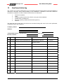
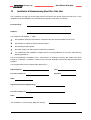
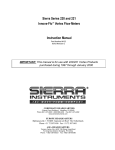
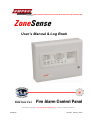
WORLD LEADER OF INNOVATIVE SOLUTIONS IN FIRE DETECTION AND ALARM SYSTEMS ZoneSense User’s Manual & Log Book E EN N5544 P Paarrttss 22 & & 44 Fire Alarm Control Panel “ Our aim is to provide ‘ Consistently Excellent Service ’ in the eyes of our customers ” MAN2749 Revision: February 2008 Quick Reference Guide Responding To An Alarm Access Level 1 ( Normal Operation) FIRE 1. Indicators - Zone FIRE Alarm Indicator - flashing ZONE 1 ZONE 2 FIRE - Common FIRE Alarm Indicator – flashing 2. To Silence the FACP Buzzer To Silence External Sounders Enter Access Level 2 – Key In Password - 3, 2, 1, 0 and Press ☞ Press ☞ SILENCE BUZZER SILENCE RESOUND 3. Indicators - Zone FIRE Alarm indicator - steady - Common FIRE Alarm indicator – steady REMOTE OUTPUT ON - REMOTE OUTPUT ON indicator – steady CONTROL ENABLED - CONTROLS ENABLED - indicator steady Disabling the Alarm Zone/s 1. Indicators 2. To Disable Zone FIRE Alarm Press ☞ 2 DISABLE / ENABLE Press Zone 1 selected ☞ 0 NEXT to select Zone in FIRE ZONE 8 ZONE 7 3. Indicators - Zone DISABLED Indicator flashing then steady - Common DISABLED Indicator – flashing then steady FAULT / DISABLED / TEST DISABLED 3 Press ☞ EXIT to EXIT the ENABLE / DISABLE mode and Access Level 2 4. Indicators - Zone DISABLED Indicator –steady - Common DISABLED Indicator –steady - CONTROLS ENABLED Indicator – off Resetting the Panel Press ☞ RESET RESETS FACP ( ZONE ALARM ) Note: Audible feedback will be given for each button press. DISABLED CONTROL ENABLED Quick Reference Guide Summary of the Fire Alarm Control Panel Indicators Indicator Condition Indication Flashing - Red A fire alarm condition has been detected or the Evacuate key has been pressed Steady - Red Controls have been enabled and the Silence/Resound key has been pressed Flashing - Red A fire alarm condition has been detected on the associated zone Steady - Red A fire alarm condition has been silenced on the associated zone FAULT/DISABLE/TEST Flashing - Amber A Fault has been detected on the zone Flashing - Amber A Fault has been detected on the zone, Disable has been pressed and Disable is being initiated Flashing - Amber The selected zone has been put into Test mode Steady - Green Power supply normal. Flashing - Green and POWER FAULT – Amber and steady Mains supply failure and / or FACP batteries have failed or are disconnected Steady - Red The Remote Output has been activated due to an alarm condition Steady - Amber The FACP has detected a microprocessor fault Flashing - Amber Selected ready to be Disabled Steady - Amber Disabled Steady - Amber Delays are programmed Flashing - Amber An alarm has been initiated and a delay or delays are timing out Steady - Amber Alarm Outputs are Disabled Flashing - Amber Fault on Alarm outputs Steady - Amber Password has been entered and NEXT, LAMP TEST ( zone test condition ), DISABLE/ENABLE, EXIT keys are active FIRE FIRE ZONE 1 ZONE 2 ZONE 8 ZONE 7 FAULT / DISABLED / TEST FAULT or DISABLED TEST POWER POWER and POWER FAULT REMOTE OUTPUT ON SYSTEM FAULT REMOTE OUTPUT DISABLED or FAULT OUTPUT DISABLED or ANCILLARY OUTPUT DISABLED DELAY ACTIVE ALARMS STATUS CONTROL ENABLED See Index ( over ) for more detailed information on the above. Note: Audible feedback will be given for each button press. Europe Ltd User’s Manual & Log Book ZoneSense TABLE OF CONTENTS Page No. 1 An Overview of Fire Alarm Systems ............................................................................................ 1 2 An Introduction to the ZoneSense Fire Alarm Control Panel ..................................................... 2 3 ZoneSense Front Panel Controls and Indicators ......................................................................... 3 3.1 3.2 3.3 4 Introduction ................................................................................................................3 Controls .....................................................................................................................3 3.2.1 Access Levels and Passwords...................................................................3 Indicators ...................................................................................................................5 FACP Operation.............................................................................................................................. 8 4.1 4.2 4.3 General ......................................................................................................................8 Operation at Access Level 1......................................................................................8 Operation at Access Level 2......................................................................................8 4.3.1 Disablement / Re-Enablement ...................................................................8 5 Normal Condition ........................................................................................................................... 9 6 Fire Alarm Condition...................................................................................................................... 9 7 Fault Condition.............................................................................................................................10 8 Disablement Condition ................................................................................................................11 9 Output Delays...............................................................................................................................12 10 Ancillary Modules........................................................................................................................13 10.1 10.2 11 8 Way Relay Board..................................................................................................13 LED Annunciator Master ( LAM ) Card....................................................................13 User Responsibilities ...................................................................................................................16 11.1 Log Book..................................................................................................................16 12 Recommended Testing Criteria...................................................................................................17 13 ZoneSense Activity Log...............................................................................................................18 14 Installation & Commissioning Hand Over Take Over ................................................................21 User’s Manual & Log Book Europe Ltd ZoneSense 1 An Overview of Fire Alarm Systems Fire alarm systems ensure the occupants of a premises receive an early warning of a potentially dangerous situation, be it smoke or fire, which necessitates the evacuation of a premises and initiation of control procedures according to a predetermined plan. Alarms Alarms can be raised; Automatically - by smoke or heat detectors, or manually - by a person sounding an alarm at the Fire Alarm Control Panel or operating a manual call point. If smoke or fire is detected the FACP responds by activating all relevant sounders, bells and other alarm outputs to provide a warning of a possible hazardous fire situation. To determine the location of an alarm, fire detection systems are split into defined zones within a building, each zone with its own detectors and manual call points independently wired back to the Fire Alarm Control Panel ( FACP ). Fault Monitoring The Fire Alarm Control Panel continuously monitors all connections between detectors, manual call points; sounders / warning devices; power supply, and back-up batteries for faults. If a fault is detected anywhere on the system, the panel responds by illuminating the associated fault light(s) on the front panel and sounding its internal buzzer. A fault output is also activated which can be say used to initiate notification of the fault to a remote monitoring centre or other warning devices. Disables If testing is to be done on the system or abnormal conditions exist certain parts of the fire alarm system can be temporarily inhibited (disabled) to suit. For example, if there is a risk of a false alarm occurring in a zone during repair works it is possible to disable that zone during the risk period and enable it again once the works have been completed. Delays In some cases a zone or designated area of protection in a system can be prone to conditions that lead to frequent and unavoidable false alarms. In areas such as these an alarm delay can be introduced on selected zones which prevent the sounding of an alarm by a selected time out period. This delay gives a responsible person time to investigate the cause of the alarm. If the alarm is found to be an actual fire hazard, the delay can be overridden and the sounders will sound. If the alarm is a false alarm, the panel can be reset. If the delay period times out without user intervention, the alarm sounders will sound. The configuration label on the inside of the door should show if any delays have been programmed into the panel. It is important the user be aware of the purpose of the “Delay” function and whether or not they apply to the installation in question as they could cause some confusion if there are expectations of an immediate FACP response during an alarm situation. Page 1 User’s Manual & Log Book Europe Ltd ZoneSense 2 An Introduction to the ZoneSense Fire Alarm Control Panel The ZoneSense Fire Alarm Control Panel ( FACP ) is supplied as a two (2), four (4) or eight (8) zone Conventional FACP and can have up to four ( 4 ) remote LED Annunciators ( LAMs ), Order Code 43100037, and one ( 1 ) 8 Way Relay Board, Order Code/s, internally housed – 4310-0050 or remotely located – 4310-0055. Features include; 9 9 9 9 Controls that have tactile and audible feedback of operation. On-site programming. A matrix type label inside the door for the recording of the FACP configuration. Panel Add On’s The ABS version front door is locked by way of two clips on the right hand side of the cabinet. A special locating key which has two raised pins that are inserted into the side of the cabinet unlocks the door. AM PA C DOOR RELEASE PINS DOOR RELEASE PINS The metal version front door is secured by way of a standard 003 keyed lock. Buzzer The buzzer provides audible: 9 indication at system start-up (3 tone bursts of increasing frequency) 9 indication of a fire condition. Tone is continuous, until the buzzer is silenced or the fire condition is cleared by reset. 9 indication of a fault condition. Tone is 1 second on, 1 second off, until the fault condition clears. 9 feedback when a key is pressed. 9 feedback when multiple keys are pressed simultaneously or illegal key press (for example RESET when at access level 1) or there is a timeout condition entering the password. Configuration All FACP’s are fitted with a label that records the configuration of the installation. ZONE ZONE TYPE 1 2 3 4 5 6 7 8 NORMAL / DELAYED NORMAL / DELAYED NORMAL / DELAYED NORMAL / DELAYED NORMAL / DELAYED NORMAL / DELAYED NORMAL / DELAYED NORMAL / DELAYED TIME DELAY (min:sec)* 0:00 1:00 2:00 3:00 4:00 5:00 6:00 7:00 ANCILLARY BOARDS TYPE FITTED NOT FITTED BRIGADE RELAYS No ANNUNCIATORS 0:30 1:30 2:30 3:30 4:30 5:30 6:30 7:30 TICK TO INDICATE DELAY * TIME DELAY COMMON TO ALL ZONES CODE EN54: 2&4 / ISO7240: 2&4 1 2 3 4 Configuration Label L Note: It is the installing engineers responsibility to ensure the configuration label correctly reflects the details of the installation and the user should be made aware of its operational meaning. Page 2 User’s Manual & Log Book Europe Ltd ZoneSense 3 ZoneSense Front Panel Controls and Indicators 3.1 Introduction The front panel consists of 9 push buttons and 31 LED indicators, and an optional enable key-switch. ANC PROG DELAY 1 2 3 4 5 6 7 8 + - SHD TIME DELAY ENABLE RS485 COM C/C ALT INPUTS + Z1 - + Z2 - + Z3 - + Z4 - + Z5 - + Z6 - + Z7 - + Z8 DETECTOR ZONES POWER FAULT SYSTEM FAULT CONTROLS ENABLED AUXILIARY POWER FAULT 3.2 REMOTE OUTPUT DISABLED ZONE 1 FAULT OUTPUT DISABLED ZONE 3 ZONE 4 ANCILIARY OUTPUT DISABLED ZONE 5 ZONE 6 TEST ZONE 7 ZONE 8 DELAY ACTIVE ALARMS STATUS OVERRIDE SILENCE RESOUND FIRE FAULT SILENCE BUZZER RESET NO C NC REMOTE NO C NC FAULT + AUX24VDC OPERATING INSTRUCTIONS ACCESS NORMAL INDICATOR STATUSLEVEL 1 (STEADY): SILENCED FIRE (FLASH): UNSILENCED (STEADY): DISABLED (FLASH): FAULT (RAPID FLASH): ZONE IN TEST OR ZONE OR OUTPUT SELECTED FOR DISABLE / ENABLE (SLOW FLASH):IF NORMAL (RAPID FLASH): IF ALREADY DISABLED OPEN ACCESS LAMP TEST: STARTS LAMP TEST SEQUENCE (PRESS FOR 3 SECS) CONTROLS ENABLED (LEVEL 2) (STEADY) EVACUATE: MANUAL ACTIVATION OF ALARMS TO DISABLE / ENABLE ZONES OR OUTPUTS: PRESS 'DISABLE / ENABLE' THIS SELECTS ZONE 1 PRESS 'DISABLE / ENABLE' TO DISABLE / ENABLE ZONE 1 OR PRESS THE 'NEXT' KEY TO SCROLL TO THE NEXT ZONE OR OUTPUT THEN PRESS 'DISABLE / ENABLE' PRESS 'EXIT' TO QUIT ZONE 2 FAULT / DISABLED / TEST REMOTE OUTPUT ON AUX REM FLT ANC RST +VE ( SLOW FLASH ): ZONE IN TEST FIRE SYSTEM STATUS POWER + 1 - + 2 - + 3 - + 4 ALARMS 0 1 DISABLED NEXT LAMP TEST 2 3 EVACUATE DISABLE / ENABLE EXIT Controls 3.2.1 Access Levels and Passwords ZoneSense has two levels of controlled operator access and are defined as level 1 and level 2. Level 1 Operational control, or normal operation, at access level 1 is limited to; 9 9 9 Silencing the buzzer Overriding any set output delays Password entry to access level 2 Level 2 Entry to access level 2 can be gained in one of two ways. 1. 2. L entering a fixed digit password (3210); or via the optionally fitted Controls Enabled / Disabled key-switch. Keys for Control Enable key switches can only be removed when the switch is in the off or disabled position. Note: When the FACP is in access level 2, the Password Entry The password is entered by pressing i. Exit e, then L ii. Enable/Disable d, then iii. Lamp Test c, and finally the iv. Next b key. CONTROLS ENABLED indicator is illuminated. 0 1 NEXT LAMP TEST 2 3 DISABLE / ENABLE EXIT Note 1: The timing between key presses must be 2 seconds or less. If not entry will timeout, the buzzer will beep and the password will have to be re-entered. Note 2: If the FACP is in access level 2 and no controls are operated within 120 seconds, then the FACP will revert to access level 1. Page 3 User’s Manual & Log Book Europe Ltd ZoneSense OVERRIDE Delay Override - Active at access level 1 and above Used to override the delays to outputs programmed into the FACP. Override is only active when the delay timer is active (delay active indicator flashing). Pressing will override the delay and cause the alarm and ancillary outputs to be immediately activated. SILENCE RESOUND Silence / Resound Alarms - Active at access level 2 Used to turn off the alarm outputs once they have been operated by a fire or evacuate condition. In the event of a new fire condition the alarm outputs will again operate. Pressing a second time reactivates the Alarm outputs once they have been silenced. Silencing an alarm will cause the Common Fire LED and any Zone Fire LED to change from flashing to steady. SILENCE BUZZER Silence Buzzer - Active at access level 1 or above Used for silencing either the fault or alarm warning buzzer at access level 1 and above. The buzzer will resound on any new event. RESET Reset - Active at access level 2 The reset control is used to return the FACP back to a quiescent state from a fire alarm condition once the alarm has been cleared. When pressed the audible feedback will sound to indicate the reset process has started L Note: Reset is also used to extinguish the System Fault indicator. EVACUATE Evacuate - Active at access level 2 Turns on and latches the alarm outputs and sets common Fire indicator to flashing. No other outputs or indicators are affected. Activating the silence / resound alarms control, will turn off the alarm outputs, and cause the common fire LED to go steady. Activating the silence / resound again will cause the alarm outputs to be activated and common fire LED to flash. Activating the reset switch, will cancel the evacuate condition, which results in the alarm outputs being turned off, and the common fire LED being extinguished. The Evacuate switch will override any delay to alarm outputs. 0 NEXT Next b - Active at access level 1 and 2. At access level 1, the Next b key is used to enter the 0 digit of the 3210 password. At access level 2, the Next for disable / re-enable. b key is used to select zone circuits for the walk test and outputs Page 4 User’s Manual & Log Book Europe Ltd ZoneSense 1 LAMP TEST Lamp Test c - Active at access level 1 and 2. At access level 1, the Lamp Test c key is used to enter the 1 digit of the 3210 password, and instigate a lamp and buzzer test if the key is depressed for 3 seconds or more. The lamp test sequentially illuminates all indicators and sounds the buzzer for approximately 1 second. L Note: 1. The lamp test will be cancelled if a fire condition is to be announced and can not be instigated if a fire condition is present. 2. The lamp test is cancelled if a fault condition is to be announced but can be instigated if a fault condition is present. At access level 2, the Lamp Test c key is used to commence the walk test. 2 DISABLE / ENABLE Disable/Enable d Active at access level 1 and 2 At access level 1, the Disable/Enable d key is used to enter the 2 digit of the 3210 password. At access level 2, the Disable/Enable d key is used to disable / enable zone circuits, alarm outputs, remote output, fault output and ancillary output. 3 EXIT Exit e Active at access level 1 and 2. At access level 1, Exit e is used to enter the 3 digit of the 3210 password. At access level 2, Exit e is used to exit from the disable / enable, and walk test procedure 3.3 Indicators There are three groups totalling 31 LED indicators on the front panel of the FACP, 10 are system status indicators, 5 are control indicators and 16 are zone indicators Where the same indicator is used for fault and disable then the fault indicator flashes and the disable is steady. The disable condition has display priority. System Status Indicators POWER Power – Green Illuminates steady when the FACP is supplied with mains power and flashes if mains fail. POWER FAULT Power Fault – Amber Illuminated steady when there is a fault within the system power supply. Faults can be no mains, high charger voltage, low battery voltage or missing / damaged battery. Page 5 User’s Manual & Log Book Europe Ltd ZoneSense SYSTEM FAULT System Fault - Amber Indicates a failure of the FACP to provide the mandatory functions such as software or hardware failure. This indicator is latched ON, until cleared by master reset. If the processor on the main card undergoes a watchdog condition, then the System fault indicator will be illuminated ON and steady, and remain ON until cleared by a master reset. CONTROL ENABLED Controls Enabled - Amber Illuminates steady to indicate the FACP is at access level 2. AUXILIARY POWER FAULT Auxiliary Power Fault - Amber Illuminated steady on a fault condition to the DC feed common to the open collector outputs and the auxiliary 24VDC feed. REMOTE OUTPUT DISABLED Remote Output Disabled - Amber Illuminates steady if the “Remote Output” open collector remote output is disabled. FAULT OUTPUT DISABLED Fault Output Relay Disabled - Amber Illuminates steady if the “Fault Output” and optional open collector fault output is disabled. ANCILLARY OUTPUT DISABLED Ancillary Output Relay Disabled - Amber Illuminates steady when the open collector “Ancillary Output” output, is disabled. TEST Test - Amber Illuminated to show that the FACP is in the Walk Test mode. The indicator is illuminated steady when the walk test is active. REMOTE OUTPUT ON Remote Output On - Red Illuminates steady when the “Remote Output” relay and open collector output are active as a result of a fire condition. Control Indicators There are five (5) control indicators within the central control area of the FACP. FIRE Common Fire - Red Common fire indicator will be flashing at the alarm rate when a fire condition is present or the evacuate control is operated (when the FACP is at access level 2). The indicator will become steady when silence resound switch is pressed. A new fire condition or activation of the evacuate control will cause the indicator to flash again. FAULT Common Fault - Amber Fault indicator - illuminated steady by any fault condition. DISABLED Disabled - Amber Disabled indicator illuminated steady by any disablement on any zone or output. Page 6 User’s Manual & Log Book Europe Ltd ZoneSense DELAY ACTIVE Delay Active - Amber The indicator is illuminated steady when one or more zones have been configured with a delay, and the FACP is in the quiescent state. When the zone that has been configured with a delay reports a fire condition the indicator will flash (at the fault rate) while the delay timer is running. Once the delay has expired the alarm outputs and ancillary output are activated and the indicator will extinguish. The indicator will remain off, until a reset is activated returning the FACP to the normal state. If the delay override is activated while the delay timer is running then the delay is overridden, the alarm and ancillary outputs are activated immediately and the indicator will extinguish. ALARMS STATUS Alarms Status - Amber This indicator is immediately above the Alarms silence / resound switch and indicates a disable condition (steady) or a fault condition (flashing at the fault rate) on any of the alarm outputs. Display priority: Disable (steady) then fault (flash) Zone Indicators There are two indicators for each alarm zone fitted to the FACP. Zone Fire – Red FIRE ZONE 1 ZONE 2 Individual zone Indicators showing when each zone is in the fire condition (flashing at the alarm rate) and will become steady when silence resound switch is pressed. An incoming alarm on another zone will cause that fire indicator to flash while the original indicator will remain steady. Zone Fault / Disabled / Test – Amber ZONE 7 ZONE 8 FAULT / DISABLED / TEST Flashes at the fault rate due to a fault condition on individual zones. Disabling that zone causes the LED to become steady. Reminder - the disablement has priority over displaying a fault condition. Other Indication The zone indicators are utilised in the disable /enable and walk test process. The following table summarises the functionality of the zone indicators: Condition Alarm (unsilenced) Alarm (silenced) Fault Disabled Normal Disable Enable Selected and under test Fire Indicator Fault/Disabled Test Indicator Flashing at the alarm rate Steady Flashing at the fault rate Steady (priority over fault) Disable / Enable Operation Rapid Flash Slow Flash Walk Test Steady – when the alarm condition Rapid Flash has been detected (3 seconds only) Page 7 User’s Manual & Log Book Europe Ltd ZoneSense 4 FACP Operation 4.1 General This section deals with the operation of the FACP. In the quiescent condition, there are no abnormal conditions or fire alarms to report, and there is no necessity to operate any of the front panel controls. The power LED will be illuminated steady, and optionally the delay active LED will be illuminated steady. If the FACP is in the fire alarm condition, the common alarm indicator is flashing, individual zone fire indicator flashing, and optionally the delay active indicator is flashing, and the panel buzzer is sounding. The remote output will be activated, and the alarm outputs and ancillary output could be activated, depending if delays are programmed 4.2 Operation at Access Level 1 It is possible to silence the buzzer by activating the silence buzzer control at access level 1. In addition the override control can be activated to cancel (or override) the delay timer. This action will cause the alarm outputs and ancillary output to be activated immediately. The lamp test control is active at access level 1. If the FACP is set to access level 2, then the reset control can be activated to return the FACP to the quiescent condition. In addition the silence / resound control can be activated to silence or resound the alarm outputs. If the FACP is in the fault condition, the common fault indicator is illuminated steady. The silence buzzer control is active, and will cause the panel buzzer to be silenced if the control is activated. 4.3 Operation at Access Level 2 When the FACP is in access level 2, the controls enabled indicator is illuminated steady, and the: 9 Reset 9 Silence / Resound 9 Evacuate 9 Disablement / Re-Enablement 9 Walk Test controls ( This is an installation and maintenance feature and is fully described in the Installation and Commissioning Manual ) are available 4.3.1 Disablement / Re-Enablement There are twelve items that can be disabled / re-enabled. These are the; 9 eight zone circuits, 9 alarm outputs (common control open collectors), 9 remote output (relay and open collector), 9 fault output (relay and open collector) and 9 ancillary output. If the FACP is at access level 2, and the Disable/Enable d key is operated, then the common disabled indicator flashes, indicating the FACP is in disable / enable procedure. If no keys are depressed for 10 seconds, the common disabled indicator returns to its previous condition, and the procedure is aborted. The panel remains at access level 2. Page 8 User’s Manual & Log Book Europe Ltd ZoneSense 5 Normal Condition The FACP is in its normal condition when there are no; 9 9 9 9 9 9 9 6 Fire alarm/s Fault/s Disable/s Testing Programming the power indicator is illuminated steady ( indicating mains power is available ) and if any zones have been programmed with delays the delay active indicator will be illuminated steady Fire Alarm Condition General Conditions 9 An alarm is triggered when any of the detectors on a zone circuit sense a fire or a manual call point is manually operated. 9 Each zone operates in isolation to the others. 9 If a zone/s circuit/s have been disabled the FACP is prevented from initiating an alarm condition on that zone circuit. 9 If a lamp test is in progress when an incoming alarm is recognised it will be aborted. 9 If the FACP is in programming mode when an alarm is recognised, then programming mode is aborted. Indication of the Fire Alarm Condition The fire alarm indications are the; 9 Common fire indicator flashes ( goes steady when the Silence Resound button is pressed) 9 Individual zone fire indicator flashes (goes steady when the Silence Resound button is pressed) 9 Buzzer sounds. Press the silence buzzer control ( reminder; the buzzer will resound for each new zone that goes into alarm ) 9 Alarm sounders and enabled outputs will be activated. Allow for the delay if the outputs have been programmed with a delay, ( for the delay setting see the configuration label ). Subsequent Alarms If at any time after the first alarm occurs other alarms are initiated the FACP will; 9 Reactivate the buzzer, alarm sounders and outputs if they have been silenced 9 Flash the Common Fire indicator 9 Flash the appropriate zone Fire indicator of the zone that has come into alarm 9 Continue to indicate ( flashing ) the previous zone or zones that were in the alarm condition ( steady when the Silence button was pressed) Reset from Fire Alarm Condition Enter the password to access level 2 and press the Reset button. Page 9 User’s Manual & Log Book Europe Ltd ZoneSense 7 Fault Condition The FACP enters the fault condition when any received signals are interpreted as a fault. The FACP recognises the following faults; 9 Individual zone circuits 9 Short or open circuit on the alarm outputs 9 Fault with the power supply – loss of mains power, loss of batteries, low battery voltage condition ( 21.6VDC without mains available) and high charger voltage ( 28.8VDC ) 9 System fault – operational main board processing, correct cabling, address setting and monitoring of any ancillary modules connected to the system 9 Short circuit on the auxiliary power output The FACP can be prevented from detecting a fault condition under the following conditions; 9 Presence of a fire alarm condition on the zone circuit 9 Disablement of a zone circuit 9 Testing of a zone circuit 9 Activation of the alarm outputs 9 Disablement of the alarm outputs Indication of the Fault Condition The presence of fault conditions are automatically indicated without manual intervention by; 9 The common fault indicator 9 The individual fault indicator for each zone. For fault conditions the individual indicators are flashing. 9 For alarm output faults, the alarms status indicator is flashing. 9 For faults with the power supply, the power fault indicator is illuminated. 9 For system fault, the system fault indicator is illuminated. 9 For a short circuit fault on the auxiliary power output, the auxiliary power fault indicator is illuminated. For all faults the buzzer will sound. The buzzer can be silenced by the silence buzzer control. The buzzer will resound for any new fault condition. Reset from the Fault Condition Except a for a System Fault, which has to be manually Reset, all faults are automatically reset on clearance of the fault. Page 10 User’s Manual & Log Book Europe Ltd ZoneSense 8 Disablement Condition Selected functions of the FACP can be temporarily disabled under controlled conditions for such purposes as testing and maintenance. One or more of the following can be selected and then disabled; In order of selection they are; ZONE LED FLASHES WHEN SELECTED AND GOES STEADY WHEN DISABLE IS PRESSED ZONE 8 ZONE 7 FAULT / DISABLED / TEST 1. Zone circuits 1-2, 1-4 or 1-8 2. Remote output REMOTE OUTPUT DISABLED 3. Fault output FAULT OUTPUT DISABLED 4. Ancillary output ANCILIARY OUTPUT DISABLED 5. Alarm outputs ALARMS STATUS Example of Disabling the Fault Output Step 1: 0 1 NEXT LAMP TEST 2 3 DISABLE / ENABLE EXIT Enter the level 2 password by pressing these 2 3 EXIT DISABLE/ ENABLE 1 LAMP TEST keys in the following order. 0 NEXT Step 2: 2 Press DISABLE / ENABLE . The FAULT/DISABLE/TEST LED and CONTROL ENABLED DISABLED LED will illuminate ( steady ) and the Zone 1 will flash.( slow for enabled, fast for disabled ) Step 3: 0 NEXT to step through the options until Press FAULT OUTPUT DISABLED LED is illuminated ( flashing ) and 2 press DISABLE / ENABLE again. The Fault Output Disabled LED will continue flashing while the disablement is being established and then become steady once the disablement is established as will the L DISABLED LED. Note 1: Disablement and re-enablement of any of the above is not affected by Reset from the fire alarm condition or the fault condition and can only be carried out by following the appropriate procedure at access level 2. Note 2: Disable has priority over the fault condition. Disabling a zone will override the alarm condition and cause any outputs activated as a result of the zone going into alarm to be cleared. Page 11 User’s Manual & Log Book Europe Ltd ZoneSense 9 Summary of Buzzer Operation The buzzer provides audible: 9 indication at system start-up (3 tone bursts of increasing frequency) 9 indication of a fire condition. Tone is continuous, until the buzzer is silenced or the fire condition is cleared by a reset. 9 indication of a fault condition. Tone is 1 second on, 1 second off, until the fault condition clears. 9 feedback when a key is pressed. Tone is 50millisecond burst 9 feedback when multiple keys are pressed simultaneously, illegal key press (for example RESET when at access level 1) or there is a timeout condition entering the password. Tone is 200 millisecond burst The buzzer: 9 Is silenced by SILENCE BUZZER but will resound on any new alarm or fault condition. 9 sounds during a lamp test. 9 sounds (fault indication), when the power supply is not calibrated. 9 sounds when calibration is successful (same tone bursts as at system start-up) 10 Output Delays For the purpose of allowing the responsible person time to investigate an alarm prior to an alarm being sounded a selectable output delay period can be introduced thus preventing unnecessary “fire management plans“ from being put into effect. If the responsible person determines the alarm is genuine or has the potential to become a fire hazard the delays can be overridden by pressing the Override key. DELAY ACTIVE OVERRIDE Indications When the delays are active and before the alarm outputs and ancillary output have been activated the buzzer will sound and delay active indicator will be flashing. Once the Override button has been pressed or the delay has timed out the Delay Active indicator will be extinguished. Operating Criteria The delay is programmed on a zone by zone basis hence if required some zones can be programmed without a delay which will mean that zone/s will immediately activate an alarm. This situation may be required where there is a hazardous area. L Note 1: The selection of the delay and the length of the delay is programmed into the FACP at access level 3. Page 12 User’s Manual & Log Book Europe Ltd ZoneSense 11 Ancillary Modules Unlike the 2 zone version the 4 and 8 zone FACP’s supports two types of RS485 controlled ancillary modules, 1 X 8 Way Relay Board and 4 X LAM’s. 11.1 8 Way Relay Board The Relay Board provides 8 X 1A voltage free changeover contacts for control and / or monitoring purposes and one (1) only can be mounted / connected; 1. internally ( Order Code 4310-0050 ) or 2. externally ( Order Code 4310-0055 ) to the cabinet. L Note: In all cases, the relays remain activated until the reset control is activated. 11.2 LED Annunciator Master ( LAM ) Card LED annunciators ( LAMs ) Order Code 4310-0037; 9 are used to display fire system information at locations that are remote from the FACP. 9 have common FACP controls, status indicators, alarm and fault/disable/test indicators; 9 generally are located in the front entrance of buildings, or in areas that are occupied by people who are responsible for responding to an emergency. 9 contain all communications interfacing and power supply circuitry,. 9 controls have tactile and audible feedback of operation. 9 terminals are a plug-in type and cater for up to 2.5mm cables. 9 communications with the Main Control Card is, RS485+, RS485-, and Screen. FAULT DISABLED FIRE TEST LAMP TEST SILENCE BUZZER FIRE FAULT DISABLED ALARMS STATUS FIRE OUTPUT STATUS TEST DELAY ACTIVE POWER LAM Front Decal Buzzer The buzzer is fitted to the PCB and provides audible: 9 indication of a fire condition. Tone is continuous until the fire condition is cleared by a reset or the buzzer is silenced locally or at the FACP 9 indication of a fault condition until the fault condition clears or the buzzer is silenced locally or at the FACP. 9 feedback when a key is pressed. 9 resounds on any new alarm or fault condition. 9 sounds during a lamp test. 9 will not sound during alarm, fault or walk tests. This is handled by the FACP Page 13 User’s Manual & Log Book Europe Ltd ZoneSense Controls There are two (2) front panel push button controls; LAMP TEST Lamp Test Initiates a lamp test of all the LAM indicators and sounds the buzzer in a logical sequence so that the operator can confirm correct operation. SILENCE BUZZER Silence Buzzer Silences the LAM buzzer. L Note: The local buzzer is activated for all alarm and fault conditions that have been recognised and announced at the FACP, and can be silenced by the FACP Indicators There are twenty four indicators on the front panel of the LAM. The indicators are in two groups, 8 system status indicators and 16 zone fire, disable/ test indicators L Note: Where the same indicator is used for fault and disable then the fault indicator flashes and the disable indication is steady. The disable condition has priority. FIRE Fire – Red in Colour The common fire indicator will be flashing at the alarm rate when a fire condition is present or the evacuate control is operated on the FACP and become steady when the alarms silenced switch is pressed at the FACP. Any new fire condition or activation of the evacuate control at the FACP will cause the indicator to flash again. FAULT Fault – Amber in Colour The fault indicator is illuminated steady by the presence of any fault on the system. In the event of a system fault, the indicator will latch until cleared by a master reset at the FACP. DISABLED Disabled – Amber in Colour The disabled indicator is illuminated steady by the presence of any disable condition on any zone, device or output. ALARMS STATUS Alarm Status – Amber in Colour Illuminated flashing at the fault rate by any open circuit or short circuit condition on any of the alarm outputs at the FACP. The indicator is non latching and extinguishes when the fault condition is cleared. When any alarm output is disabled, the indicator will be illuminated steady. Display priority: Disable (steady) then fault (flash) FIRE OUTPUT STATUS Fire Output Status – Amber in Colour When the Remote Output at the FACP is disabled, the indicator will be illuminated steady Display priority: Disable (steady) then Fault (flash) TEST Test – Amber in Colour Illuminates steady when the FACP is in the test mode. Page 14 User’s Manual & Log Book Europe Ltd ZoneSense DELAY ACTIVE Delay Active – Amber in Colour The indicator is illuminated steady when one or more zones or devices have been configured with a delay and the FACP is in the quiescent state. When the zone or device that has been configured with a delay reports a fire condition the indicator will flash while the delay timer is running. When the delay times out the appropriate outputs are activated, and the indicator will extinguish. The indicator will remain off until a Reset is initiated at the FACP to return it to the normal state. If the delay override control is activated while the delay timer is running the delay is overridden, the appropriate outputs are activated immediately and the indicator will extinguish. POWER Power – Green in Colour The indicator is illuminated steady to show that the FACP is supplied with power (mains or battery) and flashes if there is a fault with the power supply equipment. Fault can be no mains, high charger voltage, no charger voltage, low battery voltage or missing (or damaged) battery. Zone Indicators There are two indicators for each of the eight zones. Zone Fire – Red (x8) An indicator will flash when its zone is in the fire condition and become steady when the alarms silence control has been operated at the FACP. Zone Indicators Fault / Disabled / Test – Amber (x8) An indicator will flash when its zone is in the fault condition. Disablement of the zone will change LED condition to steady. Other Indication The zone indicators are utilised in the zone test facility. The zone test can be an alarm test, fault test or walk test. Refer to the following table: Condition Fire Indicator Fault/Disabled/Test Indicator Alarm (un-silenced) Alarm (silenced) Fault Disabled Normal Flashing at the alarm rate Steady - Under Test Matches Fire indicator at the FACP Flashing at the fault rate Steady (priority over fault) - Zone Test Facility Page 15 Matches the Fault/Disabled/Test indicator at the FACP User’s Manual & Log Book Europe Ltd ZoneSense 12 User Responsibilities BS 5839 - 1: 2002 is the British Standard Code for the Design. Installation and Servicing of Fire Detection and Alarm Systems for Commercial Buildings. Section 7 of the Code (User Responsibilities) states that the owner or person having control of the premises should appoint a single, named responsible person to supervise all matters pertaining to the fire alarm system. The main tasks the Responsible Person is expected to carry out have been summerised below. The summary is only intended to prompt the User’s existing understanding of his or her responsibilities with regard to the safe functionality of the Fire Alarm System. The responsible person should ensure: 1. 2. 3. 4. 5. 6. 7. 8. 9. 10. 11. 12. 12.1 Ensure documentation, eg Log Books are kept up to date and are available for inspection / updating. The indicating equipment is checked on a daily basis to ensure all faults are attended to in a timely fashion, Arrangements are in place for testing and maintenance of the system Training is supplied to persons who have also been delegated responsibilities in regard to system operation, test and emergency procedures. Appropriate action/s are undertaken to limit the number of false alarms Procedural awareness of occupants through the most effective means is maintained A clear space of at least 500mm is maintained in all directions around detection devices and that manual alarm initiating devices remain unobstructed, conspicuous and have signage applied where applicable Early consideration is given to changes, renovation or modification to the design / layout of the premises and that these changes do not degrade the effectiveness of the system If changes are made to the system all documentation is updated and if necessary delegates are retrained accordingly A spare parts requirement is established and repair servicing requirements are clearly understood by all involved. Pre-alarms are taken seriously and investigated in a timely manner. Faults are given the priority they deserve and remedial action is undertaken as appropriate. Log Book The following should be recorded in the log book; ( see sample in this manual ) 1. 2. 3. Name and contact details of the responsible person Maintenance contacts and arrangements Dates, times and information relating to all alarms, faults, false alarms, pre-alarms, testing and maintenance be it a service visit or non-routine. Page 16 User’s Manual & Log Book Europe Ltd ZoneSense 13 Recommended Testing Criteria Recommended Weekly Testing and Maintenance Criteria for testing the installation should be established in conjunction with the installer or a competent qualified person. The criteria can be but is not limited to; 1. 2. 3. Advise monitoring stations as appropriate Establish test at regular times eg 10:00 every Friday morning Advise building occupants prior to testing Weekly Testing Recommendations 1. Checking that the power indicator is illuminated 2. Initiate a lamp and buzzer test 3. Operate a manual call point during normal working hours (a different MCP should be tested each week) 4. Voice alarm systems if installed Recommended Periodic Testing The period between these test should be determined by a competent person or persons through formal risk assessment of the actual installation and should nor exceed 6 months. By way of example the tests should include, addition to the weekly testing, but are not limited to; 1. 2. 3. 4. 5. 6. 7. 8. 9. Investigation of false alarms Warning devices and monitoring Each remotely monitored facility Activation of ancillary devices eg door holders Fault indications Printers – printers are a good way of recording the test/s that have been carried out Occupancy alterations and operational clearance requirements Standby mains supply generation ( run up on load ) Standby batteries ( mains disconnected and a full alarm load simulated ) Recommended Annual Test The annual testing requirements will largely depend on the complexity of the installation and should be determined in conjunction with the installers of the equipment though in the main tests will be as for the Weekly and Periodic tests but include ALL detectors, manual call points, sounders auxiliary equipment and monitoring for correct operation. Every Five Years Competent service personnel should carry out a complete wiring check in accordance with the testing and inspection requirements of the relevant National wiring regulations and should include replacement internal batteries if they have not been replaced within the five year period. Page 17 User’s Manual & Log Book Europe Ltd ZoneSense 14 ZoneSense Activity Log The “Activity Log” must be maintained by the on site designated responsible person/s and be available for reference at all times. Every event/s relating to the installation / operation of the FACP should be recorded on completion of a task. Events include but are not restricted to; 9 9 9 9 9 9 Fire alarm conditions Tests Temporary disconnection of the FACP or any part of the installation Disablements / enablements Servicing ( both by resident and external engineers ) Failures The date and time of each entry should be also be entered along with notes on the work performed, outstanding work/s and conditions. Company / Owner: Address: “Responsible Person” - Normal Hours: Service Contacts: No. DATE Eg. 12/8/05 After Hours: EVENT REMEDIAL ACTION Zone 2 in fault. Reported 0730 Replaced EOL capacitor. Cleared at 0915 1 Page 18 SIGNED A. Fireman User’s Manual & Log Book Europe Ltd ZoneSense No. DATE EVENT REMEDIAL ACTION Page 19 SIGNED User’s Manual & Log Book Europe Ltd ZoneSense No. DATE EVENT REMEDIAL ACTION Page 20 SIGNED User’s Manual & Log Book Europe Ltd ZoneSense 15 Installation & Commissioning Hand Over Take Over The completion and sign off of this page performs the task of the formal “hand over take over” of the installation from the installation and commissioning engineer to the client or customer. Protected area: Address: In accordance with BS5839 - 1: 2002, 9 the installation has been inspected for compliance with the recommendations of the code. 9 the insulation of cables and wires has been tested. 9 the earthing has been tested. 9 the entire system has been tested for satisfactory operation. 9 it is certified that the installation complies with the recommendations of the code, other than the following deviations: The recommendations of BS5839: Part 1: 2002 Section 6, relating to servicing the system have been bought to my attention. In addition I confirm that the records, drawings, manuals and log book have been supplied. ( the representatives must complete their details here ): Representative : Title: Name For and on behalf of: Signature: Company Date: Signed (Commissioning Engineer): Name For and on behalf of: Company Date: The Installation / Commissioning Manual is held by: Name/ / Location Page 21 User’s Manual & Log Book Europe Ltd ZoneSense AUSTRALIA AMPAC TECHNOLOGIES PTY LTD EUROPE AMPAC EUROPE LTD. NEW ZEALAND AMPAC INDUSTRIES LTD. 97 Walters Drive Osborne Park 6017 Western Australia Unit 1, Norden Court, Alan Ramsbottom Way Great Harwood, Blackburn England BB6 7UR Unit 4 101 Diana Drive Glenfield, Auckland New Zealand Tel: 61 8 9242 3333 Fax: 61 8 9242 3334 Email: [email protected] Tel: 44 (0) 1254 880 201 Fax: 44 (0) 1254 880 202 Email: [email protected] Tel: 64 9 443 8072 Fax: 64 9 443 8073 Email: [email protected] UNCONTROLLED DOCUMENT NOTE: Due to Ampac’s commitment to continuous improvement specifications may change without notice.