1
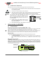
Installation &
Commissioning
of
Control & Monitoring
Add On’s
PLUS
ZoneSense
SYSTE M STATU
S
P O WER
POWER FAULT
SYSTEM FAULT
EARTH FAULT
ALARMS STATUS
FIRE
FIRE OUTPUT
STATUS
ZONE 1
FAULT OUPUT
STATUS
ZONE 5
ZONE 2
ANCILLARY OUTPUT
DISABLED
TEST
ZONE 6
ZONE 3
AMPAC
ZONE 7
ZONE 4
FIRE OUTPUT ON
SYSTEM IS NORMAL
ZONE 8
FAULT / DISABLED/TEST
N ORMAL
DELAY
ACTIVE
ALARMS
FI RE
FAULT
DISABLED
OVERRIDE
SI LENCE
R ESO UND
SILENCE
BUZZER
R ESET
EVACUATE
ENABLE
M ENU
I E NTE R
CANCEL
Fire Alarm Control Panel
E
EN
N5544 22 &
& 44 11999977
“Our aim is to provide ‘ Consistently Excellent Service ’ in the eyes of our customers”
MAN 2512
Rev: October 2005
Installation & Commissioning of Control & Monitoring Add On’s
Table of Contents
1
About This Manual............................................................................................... 2
1.1
1.2
1.3
1.4
2
Internal Communications Connector (RS485).................................................4
Programming ......................................................................................................4
Installation and Wiring of Add On Cards and Boards ...................................... 4
4.1
4.2
4.3
4.4
4.5
4.6
4.7
4.8
4.9
4.10
4.11
5
Communications ................................................................................................3
Adding Control and Monitoring Facilities ......................................................... 4
3.1
3.2
4
Purpose ...............................................................................................................2
Scope ...................................................................................................................2
References ..........................................................................................................2
PCB Removal / Replacement.............................................................................3
Wiring to the Main Card BRD25MCB ................................................................. 3
2.1
3
Page No.
Address Setting and Terminating the Communications Bus ........................5
Input Board BRD25SIPB ....................................................................................6
Relay Board BRD25EWRB.................................................................................6
Fire Fan Module BRD25FCB..............................................................................7
Fan Termination Board BRD25FTB ..................................................................8
General Indicator Card BRD25GIB -A...............................................................8
Switch and Indicator Card BRD25GIB - B ........................................................9
Zone Mimic Indicator Card ( Int. Pwr. ) BRD25GIB -C.....................................9
Zone Mimic Indicator Card ( Externally Powered. ) BRD25GIB -C ..............10
LED Annunciator Master ( LAM ) BRD25GIB - E ...........................................10
Sounder Board BRD25SOPB -A......................................................................11
Agent Release .................................................................................................... 11
5.1
5.2
5.3
5.4
5.5
5.6
Operation...........................................................................................................11
Agent Release Module BRD25ARB - A...........................................................14
Local Control Station BRD25ARB - B.............................................................15
Common Agent Release Module and Local Control Station Indicators .....16
Agent Release Termination Board BRD25ATB .............................................17
Interface Wiring ................................................................................................18
6
Appendix: Adding to the System Menu & Programming ............................... 20
7
Status and Programming Screens ................................................................... 22
7.1
7.2
7.3
Level 1 to 3 Status Screens .............................................................................22
Level 3 System Programming .........................................................................23
Level 3 Programming Menu.............................................................................24
Page 1
Installation & Commissioning of Control & Monitoring Add On’s
1
About This Manual
1.1
Purpose
This manual is an instructional tool for the installation and commissioning, of add on ancillary
cards, modules and boards that can be fitted to the ZoneSense PLUS Fire Alarm Control Panel
(FACP) and should be read in conjunction with the main Installation and Commissioning Manual.
1.2
Scope
The information within this manual is only available to and for the use of personnel engaged in
the installation and operation of the ZoneSense PLUS FACP.
ZoneSense PLUS has been designed to comply with major world standards. To ensure these
standards are not compromised in any way installation staff and operators should;
1.
be qualified and trained for the task/s they undertake;
2.
be aware this manual should be read prior to the installation and commissioning of the
ZoneSense PLUS FACP;
3.
observe anti-static pre-cautions at all times; and
4.
if a problem is encountered or there is any doubt with respect to the operational parameters
of the installation the supplier should be contacted.
1.3
References
ZoneSense PLUS Technical Manual
ZoneSense PLUS Operation & Programming Manual
ZoneSense PLUS Installation and Commissioning Manual
Apollo Detector / Device Manuals
Ampac Product Data Sheets
British Standard
EN54 Parts 2 & 4
European Standard
BS 5839
SY STEM STATUS
PO WE R
POWER FAULT
SYSTEM FAULT
ANCILLARY OUTPUT
DI SABLED
ALARMS/FAULT
DISABLED
FIRE
ZO NE 1
ZO NE 5
Z ONE 2
TEST
Z ONE 6
ZONE 3
EARTH FAULT
FAULT OUPUT
FAULT/DISABLED
FI RE OUTPUT ON
FI RE PUTPUT
FAULT/ DISABLED
AMPAC
ZO NE 7
ZONE 4
SYSTEM IS NORMAL
ZON E 8
FAULT / DISABLED/TEST
NORMAL
DELAY
ALARMS
FIRE
FAULT
OVERRI DE
SI LENCE
RES OUND
SILENCE
BUZZER
RE SET
DI SABLED
EVACUATE
ENABLE
MENU
I EN TE R
CA NCEL
Figure 1: Examples of the ABS, Metal Cabinet and Metal Cabinet with Battery Box
Page: 2
Installation & Commissioning of Control & Monitoring Add On’s
1.4
PCB Removal / Replacement
If the PCB’s have to be removed the following precautions should be observed;
2
Note:
1.
Removing the door will provide better access to the boards and ensure the hinges are
not accidentally stressed.
2.
Personal anti- static procedures must be followed.
3.
When disconnecting the telecom style connecting cable from the PCB, make sure that
the cable remains connected to at least one board to prevent it being misplaced.
Care should be taken when detaching this connector as it is necessary to depress the
Connector
small locking tab to unlock the connector from its
Push Tab Inwards
base. To reconnect the cable the connector must first
and Gently Pull
be correctly aligned then pushed into the socket so it
the Connector
locks into position.
From the Socket
4.
Carefully remove the retaining screws at each
corner of the board taking care not to damage
any of the components.
5.
Place each board into anti- static storage once removed.
Wiring to the Main Card BRD25MCB
2.1
Communications
External Communications Terminals (RS485) TB2 1, 2 & 3
The RS 485 output drives the remote cards and mimics up to a distance of 1.2km from the panel
itself. The external cabling (2x2 shielded pair plus power) is wired to TB2 +, - and earth.
Note: If a fault occurs on the communications line the common FAULT and SYSTEM FAULT
LED’S will be illuminated. The fault details can be displayed by selecting the Faults Menu.
Remote Cards
The number of cards that can be installed on the external communications bus are:
±
8 x Remote LED Mimics.
±
1 x 8 Way Remote Relay Output Board. This board provides 8 sets of normally open
(NO), normally closed ( NC ) and Common ( C ) voltage free contacts rated at 1A @
30V.
Main Card Comms Link K1
K1 MUST be inserted when only the front door panel cards and the Main Card are used as an
FACP. If this is not the case and TB2 is cabled to LED mimics and / or 8 Way Remote Relay
Boards a link is inserted in the last board to complete the communication circuit or if boards are
mounted on the back pan and communications are wired from the Main Card then the last board
in this chain MUST be terminated.
Shield
To LED Mimics and/or
Remote Relay Boards
K1
Note: the shield is
wired to
+
-
RS485
TB2
Figure 2: Wiring Detail
Page: 3
Inputs
Comms Link
Top Left Hand Corner
of the Main Board
Class Change I/P
Alert I/P
Spare I/P
Comms
SP C/C ALT
Com
1
TB3
2
3
Installation & Commissioning of Control & Monitoring Add On’s
3
Adding Control and Monitoring Facilities
A combination of one of each type of board / card, but not all of them, can be mounted on the
back pan or the front panel of the FACP to provide additional features to a standard panel. All
board inputs or outputs are programmable to any combination of zones.
±
±
±
±
±
±
±
±
±
±
Relay Board, BRD25EWRB –A or with a change of on board components it can
also be installed remotely on the external communications bus as a Remote
Relay Board BRD25EWRB -B
Input Board BRD25SIPB -.
Sounder Board BRD25SOPB.
Brigade Interface Board BRD25BBA.
Fire Fan Module consists of a Termination Board ( BRD25FTB and front panel
card BRD25FCB -.
Agent Release Module consists of a Termination Board ( BRD25ATB ), front
panel card ( BRD25ARB–A ) and if required a remote local control station
(BRD25ARB–B).
General Indicator Card. BRD25GIB -A
Switch and Indicator Card BRD25GIBA
Zone Mimic Indicator Card ( Internal Power ) BRD25GIB -C
Zone Mimic Indicator Card (External Power normally remote) BRD25GIB -D
Note: To add or remove Cards from the FACP programming go to the SYSTEM Menu.
3.1
Internal Communications Connector (RS485)
PCB mounted connectors provide serial communications to internal ancillary boards. CN9 on the
Main Card cables to CN1 or 2 on the front panel boards and CN5 on the Main Card cables to
CN1 or 2 on the back pan boards
3.2
Programming
Refer to the Operation and Programming Manual to program the above options into the FACP.
Note: The Configuration label should be updated once the panel has been upgraded.
4
Installation and Wiring of Add On Cards and Boards
CAB1911 TO MAINS EARTH
BUS 3
CN1
CAB2200
CN2
POWER
CAB2200
OTIONAL
BRIGADE BOARD
CN2
CN1
CN10
A BATT BOX IS REQ
IF THESE BRDS ARE FITTED
C N4
C N3
CN1
CN9
BUS 1
0V +27V
BUS 2
CN5
CN8
OPTIONAL BOARDS
AGENT TERMINATION
RELAY
FAN TERMINATION
INPUT
SOUNDER TERMINATION
CAB1905
MAIN CONTROL CARD
PSU1887
CN2
0V
+27V
CN6
+27V
CN3
CN4
0V
T B1-TB5
POWER
CN1
CN2
CN2 CN1
CN1
N/0
C OM N/C
ALARM 1
N/0
C OM N/C
FAULT
N/0
COM N/C
ISOLATE
N/0
C OM N/C
BATT FAIL
N/0
COM
ALARM 2
N/C
CN2 CN1
OPTIONAL CARDS
AGENT RELEASE
FAN CONTROL
GENERAL INDICATOR
CN1
CAB2200
CN2
POWER
0V +27V
CN4
C N3
CAB2200
OPTIONAL BOARDS
AGENT TERMINATION
RELAY
FAN TERMINATION
INPUT
SOUNDER TERMINATION
A BATT BOX IS REQ
IF THESE BRDS ARE FITTED
CN1
CN2
POWER
OPTIONAL CARDS
AGENT RELEASE
FAN CONTROL
GENERAL INDICATOR
0V +27V
CN2
C N3 C N4
OPTIONAL BOARDS
AGENT TERMINATION
RELAY
FAN TERMINATION
INPUT
SOUNDER TERMINATION
A BATT BOX IS REQ
IF THESE BRDS ARE FITTED
CAB2117
CAB1905
CAB1902
BOARD
IDENTIFIERS:
BRD25ARB PCB0783
BRD25ATB PCB0787
BRD25BBA PCB0779
BRD25EWRB PCB0770
BRD25FCB PCB0783
BRD25FTB PCB0780
+27v Power fitted when Relay or Termination Boards are fitted
(AGENT RELEASE MODULE)
(AGENT TERMINATION BOARD)
(BRIGADE BOARD)
(8 WAY RELAY BOARD)
(FIRE FAN MODULE )
(FAN TERMINATION BOARD)
BRD25GIB PCB0781
BRD25MCB PCB0769
BRD25PSU PCB0813
BRD25SIPB PCB0778
BRD25SOPB PCB0772
(GENERAL INDICATOR CARD)
(MAIN CONTROL CARD)
(POWER SUPPLY UNIT)
(SINGLE INPUT BOARD)
(SOUNDER OUTPUT BOARD)
CAB1925 to Batteries
Figure 3: Typical Wiring, Ancillary Card and Board Positioning Within the ABS FACP
Page: 4
Installation & Commissioning of Control & Monitoring Add On’s
4.1
Address Setting and Terminating the Communications Bus
Address Setting ( SW1 )
Except for the LED Mimics in ZoneSense PLUS FACP’s there can only be one (1) Board / Card of
each type so the address on each board is set to 1.
Note: There can be up to 8 remote LED Mimics so the address of each is set from 1-8 depending
on the number Mimics in the system. The information displayed at each location will be identical.
DIL Switch: ON = 1, OFF = 0
Address
1234
Address
01
1000
05
02
0100
06
03
1100
07
04
0010
08
On
1234
1010
0110
1110
0001
1
2
3
4
Figure 4:Address Table & Example of Switch ( SW1 ) Set to 1
Terminating the Communications Bus
LK1 is the EOL Link and must be inserted on the last board on each communications bus. If not,
a communications fault can occur.
RS485
+
-
Front Panel
Card 1
CN9
Front Panel
Card 2
Note: If Backpan boards AND remote facilities
are fitted the front panel cards are not terminated
BUS 1 ( B1 )
K1
Fit K1 if only the
Main Control
Card is used as
the FACP or
1 Bus is used
Backpan
BRD 1
CN5
Backpan
BRD 2
BUS 2 ( B2 )
INSERT
LK1 ( Link 2 in Table below )
Fit LK1 to last LCS
BUS 4 ( B 4)
To
TB1 Agent Termination Board
TB2
LCS 1
LCS 2
INSERT
LK1
If Agent Release is fitted to the FACP there will be an Agent Termination Board mounted on the Backpan.
Local Control Stations can then be fitted at some location remote from the FACP. These LCS's communicate
with the ATB via a second RS485 bus hence the last LCS in the chain will have to be terminated
Remote
Card 2
Remote
Card 1
Shield
INSERT ( Link 1 in Table below )
LK1
INSERT ( Link 3 in Table below )
LK1
BUS 3 ( B 3)
Figure 5: RS485 Communication Bus Terminating
Linking Table
Link
Bus Configuration
B1
B1,2
X & K1
X
1
X
2
3
B1,3
X
B1,2,3
B,2
B2,3
B3
X
X
X & K1
X
X
X & K1
X
X = Insert Link
B1: Bus 1 to Front Panel Cards
B2: Bus 2 to Backpan Boards
B3: Bus 3 to Remote facilities
B4: Bus 4 Local Control Station cabled to the backpan Agent Release Board.
Note: Programming and the communication process allows the Main Card to identify the type of
board it is communicating with.
Page: 5
Installation & Commissioning of Control & Monitoring Add On’s
4.2
Input Board BRD25SIPB
Description
The Input Board makes provision for 16 voltage free contacts to be terminated to 16 optically
coupled inputs. Its application is primarily for the monitoring of controlled ancillary equipment or to
initiate an action / event due to a change of state from what is accepted as the norm.
Connectors
CN1
Is designated as the input Comms .
CN2
Is designated as the output Comms to the next board.
CN3
27 Volts into the Board. Quiescent Current: 2.6mA
CN4
27 Volts to the next Board unless it is the last board in the chain then it is left empty.
Terminal Blocks
TB 2 – 9
Taking note of the Common 0v terminals connect the voltage free contacts as shown
below. Note: only the first 8 are functionally programmable in ZoneSense PLUS
SW1
There can only be 1 Input Board so the address on each board is set to 1.
LK1
Is the EOL Link and is inserted should the board be the last in the chain. If not
inserted on the last board the Main Card will initiate a communications fault.
= 0 Volts
16 Inputs are Voltage Free Contacts
8 = Input
0V
INPUTS
2
3
1
TB2
4
0V
TB3
INPUTS
6
7
5
TB4
0V
8
TB5
9
INPUTS
10
11
TB6
12
0V
13
TB7
INPUTS
14
15
TB8
16
0V
TB9
16 Inputs are Voltage Free Contacts
Inputs
0V
TB2
TB3
2
1
3
Inputs
0V
TB4
4
5
0V
TB5
6
Inputs
0V
TB7
TB8
9 10 11 1 2
8
7
Inputs
TB6
TB9
0V
13 14 15 16
#1. 27 Volts In from CN10 on the Main Card or CN4 of the previous internal board.
27V
In
#2. Select an appropriate length cable from those supplied to connect Comms & 27V.
CN1
RS485 Control In From CN2 of the
Previous Board or CN5 of the Main Card
CN2
RS485 Control Out to Next
Board or Link 1 EOL is Applied
+
-
LK1 EOL Termination
CN3
ON
CN4
Address SW
SET to 1
ON
1 2 3 4
27V To CN3 of Next Board
S W1
Note: Only the first 8 Voltage Free Contacts are functionally programable.
The second 8 can be used to independently drive LEDs 8 to 16 on the
General Indicator Board.
Figure 6: Typical Input Wiring and Board Layout
4.3
Relay Board BRD25EWRB
Relay Board ( Internal ) BRD25EWRB -A
The Relay Board has provision for 8 X 1 Amp voltage free change over contacts for control or
monitoring purposes. Communication and control cabling is the same as all other internal boards.
Quiescent Current: 2.4mA
O/P 1
COM
N/0
N/C
TB1
N/0 = Normally Open
COM = Common
N/C = Normally Closed
O/P 2
O/P 3
N/0
COM
N/C
TB2
N/0
COM
N/C
TB3
O/P 1
N/0
COM
N/C
TB1
N/0
O/P 4
COM
N/C
TB4
N/0
O/P 5
COM
N/C
TB5
N/0
O/P 6
COM
N/C
TB6
N/0
O/P 7
COM
N/C
TB7
N/0
O/P 8
COM
#1. 27 Volts In from CN10 on the Main Card or CN4 of the previous internal board.
27V
In
#2. Select an appropriate length cable from those supplied to connect Comms & 27V.
Figure 7: Board Layout
Page: 6
O/P 2
COM
N/C
TB2
N/0
O/P 3
COM
N/C
TB3
N/0
O/P 4
COM
N/C
TB4
N/0
O/P 5
COM
N/C
TB5
N/0
O/P 6
COM
N/C
TB6
N/0
O/P 7
COM
N/C
TB7
O/P 8
N/0
COM
RS485 Control In From CN2 of the
Previous Board or CN5 of the Main Card
CN2
RS485 Control Out to Next
Board or Link 1 EOL is Applied
+
-
LK1 EOL Termination
C N3
N/C
TB8
CN1
N/C
TB8
N/0
Address SW
SET to 1
SW1
ON
C N4
27V To CN3 of Next Board
1 2 3 4
ON
Installation & Commissioning of Control & Monitoring Add On’s
Relay Board ( Remote ) BRD25EWRB - B
Note#2: In a system there can only be either a remote OR an internal board, not both.
COM
N/C
O/P 2
N/0
TB1
COM
N/C
N/0
TB2
O/P 3
COM
N/C
N/0
TB3
O/P 4
COM
N/C
O/P 5
N/0
TB4
COM
N/C
N/0
TB5
O/P 6
N/C
COM
TB6
N/0
O/P 7
N/C
COM
TB7
N/0
O/P 8
COM
N/C
TB8
rev.1
O/P 1
N/0
C
///
C
RL3
NO NC
///
RL2
NO NC
C
RL1
///
Contact Legend:
N/O = Normally Open
N/C = Normally Closed
C = Common
NO NC
TB1-TB8
C
Note#1: This version can be powered from the panel or an external 27 volt source due to the on
board switched mode supply. Quiescent Current of both boards is 16mA
M10
In the remote version the Comms In and Out Terminal Block TB9 is cabled to the RS 485 Comms
terminal block TB3 on the Main Card 302 – 7690 or LED Mimic and can be installed up to 1.2kms
from the FACP.
C
RL6
C
RL7
RL8
///
///
///
///
NO NC
NO NC
NO NC
NO NC
NO NC
RL5
RL4
U6
EOL Termination
C
///
EC3AW
HY1
C
U5
U4
LK1
TB10
SW1
TB9
ON
U3
X1
CN3
U1
U2
CH4
1 2 3 4
0V
+27VDC
+27VDC
0V
A
EXTERNAL POWER
27V
In
B
COM
A
B
Address SW
COM
COMMS IN / OUT
To TB3 on the Main
Card and/or LED Mimic
Out
Figure 8: Remote Relay Board Layout
4.4
Fire Fan Module BRD25FCB
The Fire Fan Module has four ( 4 ) separate fan controls each having an On, Auto and Off
function switch and a set of three (3) monitoring LED’s. The LED’s indicate the status of the
equipment eg. Run, Fault or Stop. The two ( 2 ) arrow head keys are used to step up and / or
down through the three ( 3 ) conditions. A slip in label can also be inserted into the hinged cover
for identification purposes.
Quiescent Current: 13.5mA
Card & PCB Securing Tabs
( Top & Bottom )
PCB
P la
s t ic
WINDOWS
FOR SLIP
IN LABELS
Cli
p
In
C
N
1
La
be
l
WINDOWS
In
ON
C
N
2
Top Front Card &
PCB Securing Clips
Out
K2 Termination Link
Address
Switch
Set to 1
CN1: Communications & 27V IN from CN2 off the previous
Front Panel Card or CN9 on the Main Card
Slip In
Label
Clip On
Plastic Surround
( Push down here and pull
out to remove and insert labels )
1 2 3 4
Cle
ar
CN2: Communications & 27V OUT to Next Front Panel Card.
If Unsed the Termination Link Must be Inserted.
Lettering on slip in
labels must be at
least 5mm in height.
Figure 9: Fire Fan Module Front Panel
Page: 7
Bottom Front Card &
PCB Securing Clips
Figure 10: Fire Fan Module PCB Layout
Installation & Commissioning of Control & Monitoring Add On’s
4.5
Fan Termination Board BRD25FTB
The Fan Termination Board interfaces between the Fire Fan Module and the plant/equipment it
controls via the 24 volt 250mA Start, Stop, current limited, relay outputs and monitor inputs.
Programmable monitoring of the field equipment is achieved using 0 volts as an input level to
indicate run, fault and stop conditions of that equipment. Monitoring is programmed in the
Function Menu for a 3, 4 or 5 Wire Start / Stop, Run, Fault, Stop & Common functions. The inputs
are protected by way of resetable transorbs and resistive / capacitive networks.
Quiescent Current: 6.5mA
Connectors
CN1
RS485 Control IN from previous board or Main Card
CN2
RS485 Control OUT to next board or LK1 EOL termination is applied
CN3
27 VDC IN from CN10 of the Main Card or CN4 of the previous board
CN4
27 VDC OUT
Terminal Blocks
TB2 – 5 Are used to connect the fan control and monitoring wiring to the board.
FAN 1
FAN 1
START STOP RUN FLT STOP COM
FAN 2
FAN 2
START STOP RUN FLT STOP COM
TB2
TB3
FAN 3
FAN 3
START STOP RUN FLT STOP COM
FAN 4
FAN 4
START STOP RUN FLT STOP COM
TB4
TB5
RUN
STOP
FAN MONITORING
RUN
FLT
CN1
Cabling from FACP
to Plant / Equipment
RS485 Control Out to Next Board or Link 1 EOL is Applied
+24V O/Ps
CN3
CN4
POWER
0 V +27V
COM
FAN CONTROL
SOLID STATE OR
RELAY INTERFACE
LK1 EOL Termination
CN2
STOP
START
RS485 Control in from CN2 of Previous Board or CN5 of the Main Card
27V Out to Next Board if Applicable
ON
27V In from CN 10 on the Main Card or CN4 of the Previous Board
1 2 3 4
SW1
Address SW
INPUTS 1, 2 & 3
0V
TB 2, 3, 4 or 5
1
2
3
4
5
6
Figure 11: Fan Termination Board Layout and Typical I/O Wiring
4.6
General Indicator Card BRD25GIB -A
IMPORTANT
Note: The Cards BRD25GIB –A, B, C and D all have a common PCB. What sets them apart from
each other is not only the function they perform but how the componentry is loaded onto the card
to perform that function.
This Card indicates / displays the status of the inputs on the 16 Way Input Termination Board by
way of Program selectable tri-coloured LED’s with its function being identified on the front panel
by slip in labels.
Quiescent Current: 3 to 3.5mA depending on the application
Card & PCB Securing Tabs
( Top & Bottom )
PCB
C
N
1
Top Front Card &
PCB Securing Clips
Lettering on slip in
labels must be at
least 5mm in height.
Slip In Label
Address
Switch
Set to 1
ON
1 2 3 4
In
Out
CN1: Communications & 27V IN
from CN2 off the previous Front
Panel Card or CN9 on the Main Card
Windows for
Slip in Label
Clip On
Plastic Surround
( Push down here and pull
out to remove and insert labels )
C
N
2
CN2: Communications & 27V OUT to Next Front Panel Card.
If Unsed the Termination Link Must be Inserted.
K2 Termination
Link
Bottom Front Card &
PCB Securing Clips
Figure 12: Front Panel Card Layout
Figure 13: Front Panel Card & PCB Layout
Page: 8
Installation & Commissioning of Control & Monitoring Add On’s
4.7
Switch and Indicator Card BRD25GIB - B
This Card can effectively perform 2 different functions. Firstly the indicators monitor the first 8
inputs of the 16 Way Input Termination Board while secondly the switches can be programmed to
manually operate a specific relay in the system.
Quiescent Current: 3.6mA
C
N
1
Card & PCB Securing Tabs
( Top & Bottom )
Cle
ar
Pla
sti
c
PCB
In
La
be
l
WINDOWS FOR
SLIP
WindowsIN
for LABEL
Slip in Label
Note: As per AS 1668
lettering on any of the
slip in labels must be
at least 5mm in height.
Clip on
Plastic Surround
( Push down here and pull
out to remove and insert labels )
Top Front Panel Card &
PCB Securing Clips
In
Out
CN1: Communications & 27V IN
from CN2 off the previous Front
Panel Card or CN9 on the Main Card
Address
Switch
Set to 1
ON
1 2 3 4
Clip
C
N
2
CN2: Communications & 27V OUT to Next Front Panel Card.
If Unsed the Termination Link Must be Inserted.
K2 Termination
Link
Slip In Label
Bottom Front Panel Card &
PCB Securing Clips
Figure 14: Front Panel Card & PCB Layout
4.8
Zone Mimic Indicator Card ( Int. Pwr. ) BRD25GIB -C
The internally powered Zone Mimic Indicator Card connects to the FACP 27 volt power supply
and the internal communications bus for indication control. The card provides remote visual
indication of any Zone in an Alarm and / or Fault / Isolate condition. A maximum of 8 of these
cards can be connected to, or daisy chained together, on any one system. Slip in labels identify
the monitored Zone. The Alarm LED’s flash for an un – acknowledged alarm and are steady for
acknowledged. The Fault / Isolate LED’s flash for a Fault condition and are steady if a Zone is
Isolated.
Quiescent Current: 14mA
Card & PCB Securing Tabs
( Top & Bottom )
Isolate
Alarm Fault
PCB
C
N
1
Top Front Panel Card &
PCB Securing Clips
Slip in Label
Lettering on slip in
labels must be at
least 5mm in height.
Slip In Label
Address
Switch
Set to 1
ON
1 2 3 4
In
Out
CN1: Communications & 27V IN
from CN2 off the previous Front
Panel Card or CN9 on the Main Card
Windows for
Clip On
Plastic Surround
( Push down here and pull
out to remove and insert labels )
C
N
2
CN2: Communications & 27V OUT to Next Front Panel Card.
If Unsed the Termination Link Must be Inserted.
K2 Termination
Link
Bottom Front Panel Card &
PCB Securing Clips
Figure 15: Front Panel Card & PCB Layout
Note: Except for CN1 & 2 being fitted and TB1, HY1 the Buzzer and CN6 not being fitted the
underside of this card is the same as for the externally powered card.
Page: 9
Installation & Commissioning of Control & Monitoring Add On’s
4.9
Zone Mimic Indicator Card ( Externally Powered. ) BRD25GIB -C
The externally powered Zone Mimic Indicator Card operates in the same way as does the
internally powered version. The only difference is that the 27 volt power supply is independent of
the FACP. This card would be used when the distance involved causes a significant voltage drop
such that it may effect the reliable operation of the system or the costs involved in the cable is
offset by the availability of a remote 27 volt supply.
Quiescent Current: 13mA ( This current applies to both cards )
TB1
RS 485
In
D9
D17
D25
D18
D26
U3
X1
D2
D10
RS 485
Out
U7
D3
D11
U6
D4
D12
D19
D27
D20
D28
D21
D29
U8
D5
D13
D6
D14
D22
D30
D7
D15
D23
D31
D8
D16
D24
D32
U5
U4
Buzzer
Mute
Input
+
COM
27V
In
+
27V
Out
+
SW13
0V
0V
U2
EC3AW
Address
Switch
+
HY1
3V3 Supply
Buzzer BZ1
Termination
Link K2
Figure 16: PCB Front Layout
4.10
CN6
COM
1 2 3 4
D1
+
-
ON
U1
Figure 17: Underside of PCB
LED Annunciator Master ( LAM ) BRD25GIB - E
The LAM provides remote stand alone FACP status, Alarm and Fault / Isolate Indication of 8
zones. Two push buttons, Lamp Test and Silence Buzzer, provide for local testing of the
indicators and buzzer while the buzzer duplicates that at the FACP. A maximum of 4 LAMs with
addresses of 1 to 4 may be cabled to an FACP.
CN6
Disable
Alarm Fault
+
-
Release of the Clip On Surround
( Metal Cabinet: Push down here and pull out to remove and insert label.
ABS Cabinet: At the top RH cornner of the surround insert the surround removal
tool between it and the front panel then slide along the surround to release)
4
4
3
3
2
1
LAM
1
Figure 18: LAM Front Panel and PCB Layout
Page: 10
2
ON
LAM
2
2
LAM
3
1
PWR OUT
3
4
0V
ON
+24V
ADDRESS
SWITCH
4
Slip In Label
LAM
4
3
Lettering on slip in
label must be at
least 5mm in height.
PWR IN
2
TEST
POWER
0V
1
+24V
LAM 1 - 4
ADDRESS
SETTING
1
ALARMS STATUS
FIRE OUTPUT STATUS
DELAY ACTIVE
RS485 OUT TO NEXT LAM
( IF APPLICABLE )
COM
ON
PCB
ON
+
-
Slip in Label
4
BUZZER
FIRE
FAULT
DISABLED
3
TEST
2
LAMP
SILENCE
RS485 COMMS IN FROM FACP OR PREVIOUS LAM
COM
Windows for
1
FAULT / DISABLED
FIRE
BUZZER
MUTE
INPUT
ON
Card & PCB Securing Tabs ( Top & Bottom )
LK1
TERMINATION LINK
LINK IS INSERTED ON THE
LAST CARD IN THE CHAIN
Installation & Commissioning of Control & Monitoring Add On’s
4.11
Sounder Board BRD25SOPB -A
The Sounder Board expands the number of sounders that can be used on an FACP to 8. Each
solid state output is rated at 24VDC / 500mA. and requires a 10KΩ End of Line (EOL) resistor
regardless whether or not a sounder is wired to the circuit.
Quiescent Current: 5.6mA
Maximum Current per Output: 500mA
27V IN To Sounders 1 to 4 + / 1 SOUNDER 2
SOUNDER 3
SOUNDER 4
- 0V 27V + SOUNDER
-VE
+ VE
+ VE
-VE
- VE
+ VE
+ VE
-VE
TB2
TB3
SOUNDER 5
+ VE
-VE
SOUNDER 6
+ VE
-VE
SOUNDER
- VE
+ VE
TB1
7
SOUNDER 8
+ VE
-VE
POWER
DC IN
0V
27V
Note: Sounder polarity MUST be observed
:
:
:
:
:
:
:
:
:
:
C
N
1
::
::
::
::
::
C
N
2
To Sounders 5 to 8 + / -
To Sounders 1 to 4 + / -
27V IN
+
TB3
To Sounders 5 to 8 + / -
SOUNDER 1
-VE
+VE
SOUNDER 2
+VE
-VE
SOUNDER
-VE
+VE
TB2
3
SOUNDER 4
+VE
-VE
SOUNDER 5
+VE
-VE
SOUNDER 6
+VE
-VE
SOUNDER
-VE
+VE
TB1
7
SOUNDER 8
+VE
-VE
RS485 Control In From CN2 of the
Previous Board or CN5 of the Main Card
RS485 Control Out to Next
Board or Link 1 EOL is Applied
LK1 EOL
Termination
ON
ON
S W1
1 2 3 4
Address SW
Figure 19: Wiring Detail & PCB Layout
5
Note: Sounder polarity MUST be observed.
Agent Release
Control consists of the FACP Agent Release Module and Termination Board. Should control be
required at a point remote from the FACP an Agent Release Local Control Station can be
incorporated .
5.1
Operation
Introduction
The Agent Release Module and Termination Board communicate with the FACP via the RS485
multi-drop bus.
The Agent Release Local Control Station communicates only with the Termination Board via a
separate RS485 bus. Up to 4 Agent Release Local Control Stations can be connected to one
termination board.
The Agent Release Module operates in three modes;
1.
Automatic/Manual;
2.
Manual Only; and
3.
Disable.
The mode is selected by operating the keyswitch switch on either or module.
The keyswitch at the Agent Release Module is the only keyswitch with a Disable selection and
has the highest priority. Hence when the keyswitch is in the Disable position all other keyswitches
are ignored and the agent control system is in the Disabled mode.
Next priority is Manual Only. If any keyswitch is in Manual Only (providing the keyswitch at the
Agent Release Module is NOT in Disable), then the board is in the Manual Only mode.
Finally, the system is in the Auto/Manual mode when all keyswitches are in Auto Manual.
The pressure switch input on the termination board (which is used to confirm that the agent has
been released) can be configured to accept a normally open contact, normally closed contact, or
ignored. This is selected via the FACP on-site programming.
Page: 11
Installation & Commissioning of Control & Monitoring Add On’s
Disabled Mode
Disabled mode is selected by placing the keyswitch at the Agent Release Module in the Disabled
position. This electrically isolates the activation circuit, and results in the following:
¾
Disabled indicators at the Agent Release Module and Local Control Station are lit.
¾
Agent Release Module and Local Control Station buzzers sound.
¾
No automatic releases can be commenced.
¾
System inoperative output is activated.
Note: Disabled mode can not be overridden.
Manual Mode
When the board is in manual mode, then the
¾
Manual Only indicators at the Agent Release Module and Local Control Station are lit
¾
No automatic release sequences can be commenced.
¾
Does not interrupt a release sequence that has started
¾
System inoperative output is activated
To manually discharge the agent, the Manual Release facility at the Agent Release Module or the
Local Control Station is activated.
The manual release sequence is:
9
Manual Release Activated indicators are lit on the Agent Release Module and Local
Control Station
9
Stage 1 outputs are switch to +24VDC.
9
Stage 2 outputs are pulsed during the pre-release delay to +24VDC.
9
Start optional pre-release delay. (Selected via FACP on-site programming).
9
Upon expiration of the delay, activate the selected activation circuit and stage 2 outputs
becomes steady
9
Light the agent released LED on the Agent Release Module and Local Control Station
when pressure switch input on the termination card is activated or immediately (depends
on the pressure switch configuration).
9
FACP to activate the FIRE output and light the FIRE LED
The discharge sequence can be interrupted by the activation of the Hold input. Activation of the
Hold input prevents the release of the agent. When the Hold switch is released, the pre-release
delay is restarted. While the Hold input is activated, the stage 2 output is switched off, and the
buzzer will sound.
Auto/Manual Mode
In this mode, automatic and manual discharge is possible. For manual discharge see above.
The automatic discharge sequence is initiated when one or two zones go into alarm.
With single zone alarm activation the following discharge sequence is executed.
9
Auto Activation indicator is lit on the Agent Release Module and Local Control Station
9
Stage 1 outputs are switched to +24VDC
9
Stage 2 outputs are pulsed during the pre-release delay to +24VDC
9
Start optional pre-release delay (Selected via FACP on-site programming).
9
Upon expiration of the delay, activate the selected activation circuit and stage 2 outputs
becomes steady.
9
If configured light the agent released LED on the Agent Release Module and Local Control
Station when pressure switch input on the termination board is activated.
9
FACP to activate the FIRE output and illuminate the FIRE LED.
9
The operation of the Hold switch is as per the manual release
With dual zone activation, if the first zone goes into alarm, then the following steps are followed;
9
Flash the auto release activated LED at the Agent Release Module and
Local Control Station
9
Stage 1 outputs are switched to +24VDC
Page: 12
Installation & Commissioning of Control & Monitoring Add On’s
When the second zone goes into alarm, then the following steps are followed
9
Auto release activated LED on the Agent Release Module and Local Control Station goes
steady
9
Stage 2 outputs are pulsed during the pre-release delay to +24VDC
9
Start optional pre-release delay. (Selected via FACP on-site programming).
9
Upon expiration of the delay, activate the selected activation circuit and stage 2 outputs
becomes steady.
9
Light the Agent Released LED on the Agent Release Module and Local Control Station
when the pressure switch input on the termination board is activated (depends on the
pressure switch configuration).
9
FACP to activate the Fire output and illuminate the Fire LED
The operation of the Hold switch is as per the Manual Release.
Released Condition
When the agent has been released, and the pressure switch input has been activated, then the
board is in the released condition. The condition is shown by:
9
Agent Released indicator is lit at the Agent Release Module and Local Control Station
9
FACP Fire output and associated indicator is On.
The condition remains until reset has been activated at the FACP.
It is possible, when the agent release module is in the released condition to de-activate the Stage
1 and Stage 2 outputs. This is achieved by depressing the SILENCE/RESOUND button at the
FACP. This action will also silence the alarm outputs at the FACP and the sounder outputs on the
8 way sounder board (if fitted). If the SILENCE/RESOUND button is depressed again to instigate
the RESOUND facility, then the stage 1 and stage 2 outputs will be re-activated (as will the
onboard alarm outputs and sounder outputs on the 8 way sounder board if fitted).
Lock-Off Valve
When the lock-off valve is operated, the agent is blocked from reaching the release valve. When
the lock-off valve is operated, the following occurs:
9
Light the Blocked Mode indicator at the Agent Release Module and Local Control Station
9
Operates the system inoperative output
Fault Monitoring
The sources of fault in the system are:
9
Pressure switch monitoring circuit
9
Low pressure switch monitoring circuit
9
Lock-off valve monitoring circuit
9
Activation circuit
9
Stage 1 outputs
9
Stage 2 outputs
9
Fault in the trigger zones
9
Fault with a Local Control Station
Note #1:
The common fault indicator on the Agent Release Module and Local Control Station is
illuminated for any Fault condition.
Note #2:
For a pressure switch fault, low pressure switch fault, lock-off valve fault, stage 1
output fault and stage 2 output fault the FACP will signal the brigade.
Note #3:
When there is a fault in the activation circuit or in the trigger zones, in addition to the
above, the system inoperative output is operated.
Note #4: The FACP buzzer sounds for all faults and the LCD displays the type of fault.
Note #5: The FACP will report the type of fault on the LCD.
Page: 13
Installation & Commissioning of Control & Monitoring Add On’s
Isolation
If the trigger zones are isolated by the FACP, then the trigger zone isolated indicator at the Agent
Release Module and Local Control Station is illuminated, and the system inoperative output is
operated.
Disablement of the Trigger Zones
If the trigger zones are disabled by the FACP, then the isolate indicator at the FACP is illuminated
and the system inoperative output is operated.
5.2
Agent Release Module BRD25ARB - A
The Agent Release Module controls and monitors all the requirements for agent release and
carries the slide in label for identification of the agent and application area.
Manual Release
Switch
MANUAL RELEASE
ACTIVATED
AUTO RELEASE
ACTIVATED
AGENT
RELEASED
INITIAL AGENT
RESERVE AGENT
BLOCKED MODE
MANUAL HOLD
TRIGGER ZONE
DISABLED
COMMON FAULT
AUTO / MANUAL
MANUAL ONLY
DISABLED
AUTO / MANUAL
AGENT SELECT
PCB
MANUAL
ONLY
DISABLED
Keyswitch
MANUAL HOLD
M
A
N
U
A
L
R
E
L
E
A
S
E
Figure 20: Exploded View of Module and Front Panel Layout
Controlled Access
It is a requirement that control be secured from unauthorised use. For this reason a key switch
has been included in the control process.
AUTO / MANUAL
MANUAL
ONLY
DISABLED
Disabled, Manual Only, Auto/Manual Keyswitch In disabled mode the
selected activation circuit is electrically isolated from the activation device, and the agent can not
be released. In manual only mode, the agent can only be released manually, and in Auto/Manual
mode the agent can be released automatically or manually.
Note: The key is removable in all positions.
MANUAL HOLD
Manual Hold When activated, delays the discharge of the agent. When the switch
is depressed during the pre-discharge delay, the delay is restarted when the switch is released. If
depressed at any other time a fault is registered after a 10 second debounce time out period.
AGENT SELECT
Agent Select When activated, causes the selected agent to toggle between Initial
and Reserve.
M
A
N
U
A
L
R
E
L
E
A
S
E
Manual Release When activated causes a manual release of the agent, providing
the system is operative.
Page: 14
Installation & Commissioning of Control & Monitoring Add On’s
Agent Release Module PCB Layout
The PCB is fitted with two 2 x RJ45 connectors CN6 & 7 for power (27VDC) and communications
(RS485) for communications between the Module and the FACP Main Card.
Quiescent Current: 28.5mA
D3
U2
Auto Release
Activated
U1
D5
Manual Hold
D12
D9
RS485
&
+/- 27v
In
D13
Common Fault
U4
Manual Only
D14
Disabled
RS485
&
+/- 27v
Out
Address
Switch
K1
Termination
Link
1 2 3 4
D10
D6
CN7
CN6
ON
Trigger
Zone
U3
Disabled
D11
Blocked Mode
Reserve Agent
Initial Agent
Auto / Manual
Agent
Released
D8
D4
X1
D7
TP9
Manual Release
Activated
SW2
Select
Cutout
CN2
CN8
Cutout
Hold
Manual Release
Figure 21: Front Panel PCB Layout
Key Switch
Figure 22: Underside of the Front Panel PCB
Note: If the keyswitch is not used CN2 will carry a link so as to activate the panel.
5.3
Local Control Station BRD25ARB - B
Except for the agent select button, and the keyswitch only offering the Auto/Manual and Manual
Only selection the Local Control Station has the same indicators and controls as the Agent
Release Module.
Manual Release
Switch
MANUAL RELEASE
ACTIVATED
AUTO RELEASE
ACTIVATED
AGENT
RELEASED
INITIAL AGENT
RESERVE AGENT
BLOCKED MODE
MANUAL HOLD
TRIGGER ZONE
DISABLED
COMMON FAULT
AUTO / MANUAL
MANUAL ONLY
DISABLED
PCB
AUTO / MANUAL
MANUAL
Keyswitch
MANUAL ONLY
HOLD
M
A
N
U
A
L
R
E
L
E
A
S
E
Figure 23: Local Control Station Layout
R
E
L
E
A
S
E
M
A
N
U
A
L
Manual Release Pressing the push button starts the manual agent release
sequence. This two action safety feature prevents any accidental operation of the control and
should not be disabled.
MANUAL
HOLD
Manual Hold When pressed places the system into manual mode and prevents the
initiation of the automatic discharge sequence.
Page: 15
Installation & Commissioning of Control & Monitoring Add On’s
5.4
Common Agent Release Module and Local Control Station Indicators
MANUAL RELEASE
ACTIVATED
Manual Release Activated
Red in colour. Lit when a manual agent release sequence has commenced. This can be
instigated from the Agent Release Card and Local Control Station.
AUTO RELEASE
ACTIVATED
Auto Release Activated
Red in colour. Lit when a automatic agent release sequence has commenced. This occurs when
the zone(s) on the FACP have gone into alarm. For dual zones, the indicator should flash when
the first zone goes into alarm, and steady when the second zone goes into alarm.
AGENT
RELEASED
Agent Released
Red in colour. Lit when the pressure switch indicates the agent has been discharged.
INITIAL AGENT
Initial Agent
Yellow in colour. Lit when the initial agent activation circuit is selected.
RESERVE AGENT
Reserve Agent
Yellow in colour. Lit when the reserve agent activation circuit is selected.
BLOCKED MODE
Blocked Mode
Yellow in colour. Lit when the lock-off valve has been activated.
MANUAL HOLD
Manual Hold
Yellow in colour. Lit when a Hold button is depressed on an LCS.
TRIGGER ZONE
DISABLED
Trigger Zone Disabled
Yellow in colour. Lit when any of the trigger zones on the FACP are disabled.
COMMON FAULT
Common Fault
Yellow in colour. Lit under pressure switch, low pressure switch, lock-off valve, activation circuit,
stage 1 output, stage 2 output, Local Control Station, trigger zone(s) fault conditions.
AUTO / MANUAL
Auto/Manual
Yellow in colour. Lit when a release sequence can be started automatically or manually.
MANUAL ONLY
Manual Only
Green in colour. Lit when a release sequence can be started manually only.
DISABLED
Disabled
Yellow in colour. Lit when the release sequence can not be started automatically or manually.
Buzzer
Buzzer is activated under programmed control.
Page: 16
Installation & Commissioning of Control & Monitoring Add On’s
Local Control Station Terminal Blocks TB1 & TB2
TB2 Terminal
1
2
3
4
5
6
7
8
Assignment
RS485 + In
RS485 - In
RS485 Common
RS485 + Out
RS485 - Out
RS485 Common
Interlock+
Interlock-
TB1 Terminal
1
2
3
4
Assignment
+27V In
0V In
+27V Out
0V Out
Quiescent Current: 18.5mA
Local Control Station Layout
The Comms line is RS485 between the Local Control Station and the Termination Board.
The Interlock is a monitored input with 10KΩ EOL used to determine if air conditioning dampers
and doors are closed. Typically the agent is not discharged until all dampers / doors are closed.
U2
Auto Release
Activated
D5
Manual Hold
Trigger
Zone
U3
Disabled
CN5
+
_
RS 485
IN
D9
D13
+
_
INTER
LOCK
+
_
COM
SW2
Address
Switch
HY1
+
+27V
In
Cutout
CN8
Manual Release
Cutout
0V
CN2
+
+27V
Out
BUZZER
BZ1
0V
Key Switch
TB1
Hold
Figure 24: Top PCB Layout
Figure 25: Bottom PCB Layout
Agent Release Termination Board BRD25ATB
4K7
LCP CABLE
RS485 Control
In From CN2 of
Previous Board
RS485 Control
Out to Next
Board or Link 1
EOL is Applied
27V In
27V to
Next Board
C
N
1
+ PSW -
TB2
NC
NO
Contact
Rating
1A & 24V
U1
N/0 COM
+ LOCK-
+
NC
NO
NO
Contact
Rating
1A & 24V
C
C
RL1
RL2
RL4
-L
-
N/0 COM
TB5
NO
NO
+L
C
RL5
RL6
N/0 COM
-
+L
RELEASE
MAIN
+
-
RESV
+
-
TB7
NO
NO
Contact
Rating
1A & 24V
COMM
10K
EOL
TB6
NC
NC
-L
+
NC
COMM
RL7
C
RL3
-L
+L
U2
U4
EOL
Termination
LK1
CN3 CN4
+
Contact
Rating
1A & 24V
COMM
10K
EOL
10K
EOL
NC
NC
U3
C
N
2
-
TB3 TB4
STAGE2
STAGE1
+ L.PSW-
///
TB1
+ - Outputs are Monitored
GAS SYST.
FIRED INOP.
///
SIG+
0VDC
SCRN SIG+24VDC
Monitored
INPUTS
22K
EOL
///
5.5
Termination
Link
EC3AW
3V3 POWER
SUPPLY
1 2 3 4
Cutout
Disabled
RS 485
OUT
Q2
U5
U10
Address Setting
Quiescent Current:12mA
ON
CN5
1 2 3 4
U9
U7
SW1
Figure 26: Agent Termination Board PCB Layout
Page: 17
ON
D14
U4
Manual Only
K1
COM
Common Fault
D10
D6
Auto / Manual
TB2
D12
Blocked Mode
Reserve Agent
Initial Agent
///
U1
D11
Agent
Released
D8
D4
X1
D7
+
D3
Manual Release
Activated
Cutout
Installation & Commissioning of Control & Monitoring Add On’s
The Agent Release Termination Board interfaces to the;
1.
The FACP via CN1, CN2 continuing the RS485 communications bus if required. LK1 is
inserted if this is the last backpan board on the bus.
2.
LCS’s ( up to 4 ) via TB1. LK1 is inserted in the last board in the RS485 Bus
3.
Monitored Inputs: via TB2. ( EOL Resistance 22KΩ, Series Resistance 4K7Ω )
(a)
Pressure Switch ( PSW ) agent released
(b)
Low Pressure Switch ( LPSW ) agent storage cylinder pressure has dropped to a predetermined level; and
(c)
Interlock, the manual lock-off valve has been operated.
4.
Gas Fired: Output via RL2 N/O contacts rated at 1A @ 24VDC wired to TB3. Used to
indicate to other monitoring devices the agent has been released.
5.
System Inoperative: via RL1 N/O contacts rated at 1A @ 24VDC wired to TB4. Used to
warn by way of signage / audible alarm and/or monitoring that the system is inoperative.
6.
Stage 1: Output; initiates the visual and audible Fire Alarm and Evacuate warnings.
(a)
Monitored; via RL4 C/O contacts wired to TB5 1 & 2 ( EOL required 10KΩ ) and
(b)
un-monitored; via RL5 N/O contacts wired to TB5 3 & 4.
7.
Stage 2: output; initiates the visual and audible Fire Alarm and Do No Enter warnings
(a)
Monitored; via RL6 C/O contacts wired to TB6 1 &2; ( EOL required is 10KΩ ) and
(b)
Un-monitored; via RL3 N/O contacts wired to TB6 3 & 4
8.
Release: Main actuating circuit, monitored (10KΩ EOL required) via TB7 1 & 2 ( 2A current
limited ),
Release: Reserve actuating circuit, monitored (10KΩ EOL required) via TB7 3 & 4 ( 2A
current limited )
(a)
To Pyrogen Igniter ( max of 10 )
(b)
Metron Igniters ( max of 10 – a series 2watt 18Ω resister must be added to the circuit )
(c)
Solenoid valve ( max current of 2 amps & 27VDC )
Interface Wiring
Monitored Inputs TB2 1 & 2
Pyrogen,
This input relies on a thermal fuse used in conjunction with 22KΩ EOL and 4K7Ω
series resistors. The type of agent release mechanism has to be set in the
Programming Menu for the input to function as per the manufacturers specifications
and be in accordance with the relevant Standard.
C2
TB2
-VE
Pyrogen Release
Brd. 302-740
TB1
Pyrogen
Canister
+VE
5.6
D1
R2
R1
302-7400
17/10/00
4K7
FUSE
Pyrogen
Release
MAIN / RESERVE
Point
RELEASE
Termination Board
C1
To TB7
MAIN or
RESERVE
Release
22K
EOL
TB2
1
Figure 27: Pyrogen Wiring
Page: 18
- PSW
+
2
Installation & Commissioning of Control & Monitoring Add On’s
Solenoid & Metron
This input relies on N/O or N/C relay contacts used in conjunction with 22KΩ EOL and 4K7Ω
series resistors. The type of agent release mechanism and contacts used has to be set in the
Programming Menu for the input to function as per the manufacturers specifications and be in
accordance with the relevant Standard.
Note: The PSW, LPSW & the Interlock Mechanisms are all
mounted onto the top of the cylinder containing the Agent
Agent
Distribution
4K7
To TB7
MAIN or
RESERVE
Release
22K EOL
22K
EOL
4K7
Termination
Board
+ - +
22K EOL
4K7
- +
-
Agent
MAIN / RESERVE
RELEASE
PSW
LPSW
LOCK
Figure 28: Solenoid, Metron PSW, LPSW and “LOCK” Wiring
LPSW & Lock
These inputs are also monitored and should be wired as shown above
TB3
RL2A
*
= MOV
35V
1
*
2
*
To Monitoring
Interface / Device
TB4
RL1A
+
System Inoperative
+27V Current
Limited to1A
0V
1
Figure 29: Gas Fired Wiring
As can be seen from above the;
0V
2
-
To Sys
Inop Mon
Figure 30: System Inoperative Wiring
Gas Fired Output can be wired to any interfacing or 1A monitoring circuit that requires a closed
relay contact to indicate a change of state. This could be a relay or a solid state device.
System Inoperative Outputs 27V @ 1A to supply interfacing, signage and aural alarms to
indicate the system has been taken out of service or has developed a fault.
Stage 1, Stage 2
Stage 1
or
RL4A
RL4B
Stage 2
RL6A
TB5 / 6
+ve
1
-ve
*
RL6B
2
3
RL5A
RL3A
The above circuitry applies to both
TB5 ( Stage 1 ) and TB6 ( Stage 2 )
*
*
= MOV
35V
4
+(-)
1 or 2 Way
Signage
-(+)
Agent Termination Board Relays
Figure 31: Stage 1 and 2 Wiring
10K EOL
To audible / visual
device or interface
*
0V
10K
EOL
TB5 = Stage 1
TB6 = Stage 2
Solenoid
+ -
+ TB7
MAIN
RESV
Figure 32: Agent Release
Solenoid Wiring
Current Generation Signage
Stage 1 displays the warning sequence ie discharge of the agent is imminent while Stage 2
communicates the discharge of the agent is or has occurred DO NOT ENTER.
2nd Generation Signage
Is able to display both phases of agent release.
Page: 19
Installation & Commissioning of Control & Monitoring Add On’s
6
Appendix: Adding to the System Menu & Programming
In this example 1 Input Board, 1 Relay Board and 1 Sounder Board will be added to the system. The
Display and Zone Labels will then be edited.
Step 1:
Go to the SYSTEM MENU and then follow the procedure as set out below.
ENTER
MENU
PASSWORD ENTER
SYSTEM
MENU
ENTER
BUZZER
FACTORY DEFAULT
PASSWORD IS 3333
ALARM
YES / NO
RESOUND
YES / NO
EXAMPLE
SET RESOUND TO YES
THEN MOVE TO ALARM
EXAMPLE
SETTING
PASSWORD
0123
EARTH MON
YES / NO
MENU
ENTER
YES
MENU
ENTER
UPDATE PROGRAM
MOVE TO ALARM
YES / NO
PASSWORD
0000
BRIGADE
NO
NO BRIGADE INTERFACE BOARD INSTALLED
EXAMPLE OF SETTING
THE SYSTEM MENU IF A
RELAY BOARD IS INSTALLED
PASSWORD
0100
PASSWORD
0120
MENU
ENTER
RELAYS
YES
IF THESE 4
OPTIONS
ARE NOT SET
TO YES THEY
WILL NOT
APPEAR
IN THE
TEST MENU
FIRE FAN
NO
PASSWORD
0123
AGENT
NO
MENU
ENTER
MENU
Y E S ENTER
UPDATE PROGRAM
NO FIRE FAN MODULE INSTALLED
NO AGENT RELEASE MODULE INSTALLED
EXAMPLE OF SETTING
THE SYSTEM MENU IF A
SOUNDER BOARD
IS INSTALLED
PASSWORD
ACCEPTED
SOUNDERS
YES
MENU
Y E S ENTER
UPDATE PROGRAM
SYSTEM
MENU
ENTER
INDICATE
NO
NO INDICATOR CARD INSTALLED
SW INDIC
NO
NO SWITCH & INDICATOR CARD INSTALLED
CANCEL
EXAMPLE OF SETTING
THE SYSTEM MENU IF AN
INPUT BOARD IS INSTALLED
LEGEND:
PRESS ENTER TO ACCESS
MENU
ENTER MENU AND UPDATE PROGRAM
OR CHANGE MENU
INPUTS
YES
PRESS: MOVE FORWARD
OR BACKWARD
THROUGH THE MENU
MENU
Y E S ENTER
UPDATE PROGRAM
PRESS THESE KEYS
TO SET YES / NO
MIMIC
0 TO 8
PRESS MOVE FORWARD
THROUGH THE MENU
CANCEL
NO MIMIC INSTALLED
PRESS CANCEL AT
ANY TIME TO BACK
OUT OF THE MENU
FACTORY SET
CAN NOT BE
CHANGED
C O DE
AS4428
Example of Adding Input, Relay and Sounder Boards in the SYSTEM MEU
Page: 20
Installation & Commissioning of Control & Monitoring Add On’s
Step 2
LEGEND:
PROGRAM
ACF
ISOALTE PRESS ACF TO ISOLATE CIRCUITS EXTERNAL TO FACP
MENU
ENTER
MENU
ENTER
ACF
ISOALTE
ZONES
CANCEL PRESS CANCEL AT ANY TIME TO BACK OUT OF THE MENU
CANCEL
MENU
ENTER
PRESS ENTER TO GO TO SUB MENU, SET MENU OR UPDATE PROGRAM
PRESS MOVE FORWARD / BACKWARD THROUGH THE MENU
PRESS MOVE FORWARD THROUGH THE MENU
CLOCK
MCP ZONE
Z#
OUTPUTS
IN THIS EXAMPLE RELAY 3 IS ACTIVATED BY ZONES 1,4 OR 8
WHEN IN ALARM OR I/P's 1,3 OR 7 OF THE I/P BOARD ARE ON
RELAYS
MENU
ENTER
RELAY 3
R3 Z-FLT
.......
MENU R3 Z-ALRM
ENTER
1..4...8
ON
MENU
ENTER
MENU
ENTER
OF F
FIRE FAN
SELECT RELAY 3
R3 Z-ISOL
.......
R3 SWITCH
.......
R3 I/P
1.3...7.
MENU
ENTER
UPDATE MENU
ON
OF F
TURN OFF
2,3,5,6,7
MENU
ENTER
UPDATE MENU
TURN ON
1,3&7
AGENT
IN THIS EXAMPLE SNDR O/P 2,5&8
ARE ACTIVATED BY ZONES 1,5&8
MENU
SOUNDERS ENTER
SET SNDR
MENU
BRD O/P
ENTER
.2..5..8
SET ZONE
TO
ACTIVATE
1...5..8
MENU
ENTER
UPDATE MENU
1 TO 8
1 TO 8
ON
DISPLAY
########
Z LABELS
MENU
ENTER
MENU
ENTER
EDIT
TEXT
OF F
SELECT
Z ONE
MENU
ENTER
TO EDIT DISPLAY
TEXT USE
TO MOVE THROUGH THE
ALPHABET / NUMBERS
TO MOVE THROUGH
THE WORD
EDIT
TEXT
Programming the Relays and Sounders to be Activated by Zones and Editing Text
MAIN CARD
RELAY BOARD
CN5
CN1
CN2
EOL Not Used
CN10
+
-
+
-
CN3
INPUT BOARD
CN4
+-
CN1
ON
1 2 3 4
Set to 1
CN2
EOL Not Used
Address SW
+
-
CN3
CN4
+
-
CN1
Address SW
ON
1 2 3 4
Set to 1
-
SOUNDER
TB3 BOARD
+
Address SW
CN2
ON
EOL LINK
INSERTED
IN LAST
BOARD OF
THE CHAIN
1 2 3 4
Set to 1
RS485 and 27V Cabling for the Installation of a Relay, Input and Sounder Board as in the SYSTEM and
PROGRAMMING Menu Structures Above
Page: 21
Installation & Commissioning of Control & Monitoring Add On’s
7
Status and Programming Screens
The following shows all the screens that are possible in the FACP and how to navigate through
them. I f a screen is not available it means that option has not been installed or is not available to
the model in use.
Operating Main Menu
STATUS
7.1
STATUS
LEVEL 1
FAULTS
MENU
ENTER
LEVEL 3
PROGRAMMING
SYSTEM
Level 1 to 3 Status Screens
MENU
ENTER
MENU
ENTER
BRIGADE
MENU
ENTER
PRESS THESE KEYS
TO SET YES / NO, OFF / ON,
OFF NORMAL
LEGEND:
PRESS ENTER
PRESS: MOVE FORWARD
OR BACKWARD
THROUGH THE MENU
CANCEL
MENU
ENTER
OUTPUTS
LEVEL 2
DISABLE
TEST
RELAYS
FIRE FAN
MENU
ENTER
PRESS MOVE FORWARD
THROUGH THE MENU
ALARM 1
OFF / ON
RELAY 1
OFF / ON
FAN 1
OFF / ON
ALARM 2
OFF/NORM
FAULT
OFF / ON
RELAY 2
OFF / ON
ALARM 3
OFF/NORM
DISABLE
OFF / ON
ALARM 4
OFF/NORM
FIRE
OFF/NORM
SOUNDERS
AGENT
MENU
ENTER
ALARM 1
OFF/NORM
PRESS CANCEL AT
ANY TIME TO BACK
OUT OF THE MENU
CANCEL
MENU
ENTER
MENU
ENTER
INPUT
VOLTAGE
MENU
ENTER
MENU
ENTER
SNDR 1
OFF/NORM
INPUT 1
OFF / ON
BATT V
26.8V
FAN 2
OFF / ON
SNDR 2
OFF/NORM
INPUT 2
OFF / ON
CHRGR V
27.0V
RELAY 3
OFF / ON
FAN 3
OFF / ON
SNDR 3
OFF/NORM
INPUT 3
OFF / ON
SYSTEM V
27.0V
BATT FAIL
OFF / ON
RELAY 4
OFF / ON
FAN 4
OFF / ON
SNDR 4
OFF/NORM
INPUT 4
OFF / ON
ALARM 2
OFF / ON
RELAY 5
OFF / ON
SNDR 5
OFF/NORM
INPUT 5
OFF / ON
FAULT
OFF/NORM
RELAY 6
OFF / ON
SNDR 6
OFF/NORM
INPUT 6
OFF / ON
ANC OUT
OFF/NORM
RELAY 7
OFF / ON
SNDR 7
OFF/NORM
INPUT 7
OFF / ON
RELAY 8
OFF / ON
SNDR 8
OFF/NORM
INPUT 8
OFF / ON
AGENT
OFF/NORM
Page: 22
SOFTWARE
VER E1.2
Installation & Commissioning of Control & Monitoring Add On’s
7.2
Level 3 System Programming
ENTER
MENU
PASSWORD ENTER
SYSTEM
MENU
ENTER
BUZZER
MENU
ENTER
FACTORY DEFAULT
PASSWORD IS 3333
EXAMPLE OF
SETTING
PASSWORD
0123
EXAMPLE
SET RESOUND TO YES
THEN MOVE TO ALARM
YES
EARTH MON
YES / NO
MENU
ENTER
MENU
ENTER
PASSWORD
0000
PASSWORD
0100
PASSWORD
0120
PASSWORD
0123
ALARM
YES / NO
RESOUND
YES / NO
UPDATE PROGRAM
MOVE TO ALARM
YES / NO
BRIGADE
YES / NO
RELAYS
YES/ NO
FIRE FAN
YES / NO
NOTES:
TO ADD OR DELTE
FROM THE SYSTEM SET
TO YES OR NO AND THEN
GO TO THE PROGRAM
MENU TO SET THE
OPERATIONAL
PARAMETERS
IF THESE OPTIONS
ARE NOT SET TO YES
THEY WILL NOT APPEAR
IN THE TEST, STATUS OR
PROGRAM MENU
AGENT
YES / NO
MENU
ENTER
PASSWORD
ACCEPTED
SOUNDERS
YES / NO
SYSTEM
INDICATE
YES / NO
MENU
ENTER
SW INDIC
YES / NO
CANCEL
LEGEND:
MENU
ENTER
INPUTS
YES / NO
PRESS ENTER TO ACCESS
MENU AND UPDATE PROGRAM
OR CHANGE MENU
PRESS: MOVE FORWARD
OR BACKWARD
THROUGH THE MENU
PRESS THESE KEYS
TO SET YES / NO
MIMIC
0 TO 8
PRESS MOVE FORWARD
THROUGH THE MENU
CANCEL
CODE
EN54
FACTORY SET
CAN NOT BE
CHANGED
Page: 23
PRESS CANCEL AT
ANY TIME TO BACK
OUT OF THE MENU
Installation & Commissioning of Control & Monitoring Add On’s
7.3
Level 3 Programming Menu
PROGRAM
MENU
ENTER
ZONE S
MENU
ENTER
SELECT
ZONE 1 - 8
NORMAL
NON LATCH
AVF
AGENT T2
AGENT T1
DOUBLE
KNOCK
1 TO 8
LEGEND:
ZONE
DELAY
MENU
ENTER
8
SELECT
DELAY
SELECT
ZONE 1-8
ACF
ISOALTE PRESS ACF TO ISOLATE CIRCUITS EXTERNAL TO FACP
MENU
ENTER
ASSIGN MCP
1 TO A ZONE
ACF
ISOALTE
MENU
ENTER
CLOCK
MENU
ENTER
SELECT
DAY
TIME
CHANGE
DAY TIME
MENU
ENTER
O N MENU
MENU
ENTER
ENTER
OFF
1 TO 8
RELAYS
MENU
ENTER
SELECT
RELAY
1 TO 8
ENTER
FIRE FAN
UPDATE MENU
ALARM
ZN 1 TO 8
O N MENU
ENTER
SET
SNDR #
12345678
MENU
ENTER
SET
ZONE #
12345678
INHIBIT
ZN 1 TO 8
INDICATE
STYLE
MENU
ENTER
SELECT
STYLE #X
SELECT
BGD ALM 2
ZN 1 TO 8
FIRE OUT
EVAC Y/N
R# SWITCH
1 TO 8
BACKOUT OF MENU
N: NO
RE SET
MENU
ENTER
YES
NO
FUNCTION
3,4,5 WIRE
3 MENU
4 ENTER
5
MENU
ENTER
RELEASE
P YR OGEN
PRESS S/W
N/O
RELEASE
SOLENOID
PRESS SW
N/ C
RELEASE
METRO N
PRESS SW
NONE
MENU
ENTER
MAX
SET STYLE FROM
1 TO MAX
AVAILABLE
IN MODULE
R# I/P
1 TO 8
CANCEL
UPDATE MENU
MENU
ENTER
MENU
SOUNDERS ENTER
R# Z-ISOL
1 TO 8
OFF
1 TO 4
AGENT
R# Z-FLT
1 TO 8
OFF
MENU
ENTER
SELECT
BGD ALM 1
ZN 1 TO 8
Y: YES
O N MENU
SELECT
FAN
1,2,3,4
ANC OUT
ZN 1 TO 8
ALARM 4
ZN 1 TO 8
ALARM 3
ZN 1 TO 8
UPDATE MENU
EXAMPLE OF ACTIVATING ZONE TO TURN ON/OFF SELECTED OUTPUT
MENU R# Z-ALRM
ENTER
1 TO 8
1 TO 8
MENU
ENTER
PRESS ENTER TO GO TO SUB MENU, SET MENU OR UPDATE PROGRAM
PRESS MOVE FORWARD THROUGH THE MENU
ALARM 2
ZN 1 TO 8
ALARM 1
ZN 1 TO 8
PRESS CANCEL AT ANY TIME TO BACK OUT OF THE MENU
PRESS MOVE FORWARD / BACKWARD THROUGH THE MENU
MOVE
TH ROUGH
DAY TIME
OUTPUTS
CANCEL
CANCEL
RELEASE MENU
CONSTANT ENTER
EXAMPLE OF SELECTING FUNCTION WIRE TO BE USED
AUTO DELAY
SET 0 - 60S
MAN DELAY
SET 0 - 60
LCS
1
SET
0 - 60 SEC
SET
0 - 60 SEC
SET
1 TO 4
NOTE:
THESE MENUS ARE ONLY AVAILABLE
IF RELAYS, FIRE FAN, AGENT
SOUNDERS HAVE BEEN CHANGED
TO YES IN THE SYSTEM MENU
1
DISPLAY
########
MENU
ENTER
Z LABELS
MENU
ENTER
EOL
10uf
MENU
ENTER
EOL
RES 3K3
Z ON E
S/ C
MENU
ENTER
Z ON E
ALARM
EDIT
TEXT
SELECT
Z ON E
MENU
ENTER
EDIT
TEXT
EOL
RES4K7
TO EDIT DISPLAY
TEXT USE
E OL
RES 6K8
TO MOVE THROUGH THE
ALPHABET / NUMBERS
EOL
RES 10K
ZONE
FAULT
Page: 24
TO MOVE THROUGH
THE WORD
Installation & Commissioning of Control & Monitoring Add On’s
AUSTRALIA
AMPAC TECHNOLOGIES PTY LTD
EUROPE
AMPAC EUROPE LTD.
NEW ZEALAND
AMPAC INDUSTRIES LTD.
97 Walters Drive
Osborne Park 6017
Western Australia
Unit 1, Norden Court,
Alan Ramsbottom Way
Great Harwood, Blackburn
England BB6 7UR
Unit 4 101 Diana Drive
Glenfield, Auckland
New Zealand
Tel: 61 8 9242 3333
Fax: 61 8 9242 3334
Email: [email protected]
Tel: 44 (0) 1254 880 201
Fax: 44 (0) 1254 880 202
Email: [email protected]
Tel: 64 9 443 8072
Fax: 64 9 443 8073
Email: [email protected]
UNCONTROLLED DOCUMENT
NOTE: Due to Ampac’s commitment to continuous improvement specifications may change without notice.